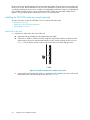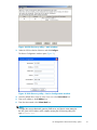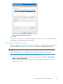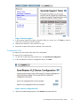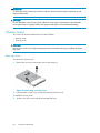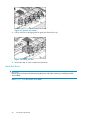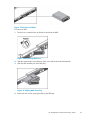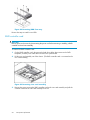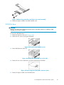
1
HP StorageWorks 1000i Virtual Library System user guide 406685-002 Part number: 406685-002 Second edition: October 2006 Legal and notice information © Copyright 2006 Hewlett-Packard Development Company, L.P. Hewlett-Packard Company makes no warranty of any kind with regard to this material, including, but not limited to, the implied warranties of merchantability and fitness for a particular purpose. Hewlett-Packard shall not be liable for errors contained herein or for incidental or consequential damages in connection with the furnishing, performance, or use of this material. This document contains proprietary information, which is protected by copyright. No part of this document may be photocopied, reproduced, or translated into another language without the prior written consent of Hewlett-Packard. The information is provided “as is” without warranty of any kind and is subject to change without notice. The only warranties for HP products and services are set forth in the express warranty statements accompanying such products and services. Nothing herein should be construed as constituting an additional warranty. HP shall not be liable for technical or editorial errors or omissions contained herein. Adobe® and Acrobat® are trademarks of Adobe Systems Incorporated. Intel and Itanium are trademarks or registered trademarks of Intel Corporation or its subsidiaries in the United States and other countries. Microsoft®, Windows®, Windows NT®, and Windows® XP are U.S. registered trademarks of Microsoft Corporation. UNIX® is a registered trademark of The Open Group. Printed in the US. Contents About this guide . . . . . . . . . . . . . . . . . . . . . . . . . . 11 1 Introduction . . . . . . . . . . . . . . . . . . . . . . . . . . . . 15 Intended audience . . . . . . . Prerequisites . . . . . . . . . Related documentation . . . . . Document conventions and symbols Rack stability . . . . . . . . . HP technical support . . . . . . Subscription service . . . . . . HP-authorized resellers . . . . . HP web sites . . . . . . . . . Documentation feedback . . . . . . . . . . . . . . . . . . . . . . . . . . . . . . . . . . . . . . . . . . . . . . . . . . . . . . . . . . . . . . . . . . . . . . . . . . . . . . . . . . . Features . . . . . . . . . . . . . . . . . . . Benefits . . . . . . . . . . . . . . . . . . . Important concepts . . . . . . . . . . . . . . . Internet SCSI (iSCSI) protocol . . . . . . . . Disk-to-Disk-to-Tape (D2D2T) backup capabilities Redundant Array of Independent Disks (RAID) . Emulation . . . . . . . . . . . . . . . . . Retention planning . . . . . . . . . . . . . . . . . . . . . . . . . . . . . . . . . . . . . . . . . . . . . . . . . . . . . . . . . . . . . . . . . . . . . . . . . . . . . . . . . . . . . . . . . . . . . . . . . . . . . . . . . . . . . . . . . . . . . . . . . . . . . . . . . . . . . . . . . . . . . . . . . . . . . . . . . . . . . . . . . . . . . . . . . . . . . . . . . . . . . . . . . . . . . . . . . . . . . . . . . . . . . . . . . . . . . . . . . . . . . . . . . . . . . . . . . . . . . . . . . . . . . . . . . . . . . . . . . . . . . . . . . . . . . . . . . . . . . . . . . . . . . . . . . . . . . . . . . . . . . . . . . . . . . . . . . . . . . . . . . . . . . . . . . . . . . . . . . . . . . . . . . . . . . . . . . . . . . . . . . . . . . . . . . . . . . . . . . . . . . . . . . . . . . . . . . 2 Setting up the VLS1000i hardware . . . . . . . . . . . . . . . . . Preparing for the installation . . . . . . . . . . . . . Tools for installation . . . . . . . . . . . . . . Taking ESD precautions . . . . . . . . . . . . . Selecting a location . . . . . . . . . . . . . . . . Unpacking . . . . . . . . . . . . . . . . . . . . Racking (optional) . . . . . . . . . . . . . . . . . Optimum environment for a racked system (optional) Space and airflow requirements . . . . . . . Temperature requirements . . . . . . . . . . Power requirements . . . . . . . . . . . . Electrical grounding requirements . . . . . . Installing the VLS1000i node into a rack (optional) . Install rails in the rack . . . . . . . . . . . Attach rails to the VLS1000i (appliance) . . . . Install appliance in rack . . . . . . . . . . Installing VLS1000i cables . . . . . . . . . . . . . 3 Configuring the VLS1000i . . . . . . . . . . . . . . . . . . . . . . . . . . . . . . . . . . . . . . . . . . . . . . . . . . . . . . . . . . . . . . . . . . . . . . . . . . . . . . . . . . . . . . . . . . . . . . . . . . . . . . . . . . . . . . . . . . . . . . . . . . . . . . . . . . . . . . . . . . . . . . . . . . . . . . . . . . . . . . . . . . . . . . . . . . . . . . . . . . . . . . . . . . . . . . . . . . . . . . . . . . . . . . . . . . . . . . . . . . . . . . . . . . . . . . . . . . . . . . . . . . . . . . . . . . . . . . . . . . . . . . . . . . . . . . . . . . . . . . . . . . . . . . . . . . . . . . . . . . . . . . . . . . 11 . . 11 . . 11 . 12 . 12 . 13 . 13 . 13 . 13 . 13 . . . . . . . . . . . . . . . . . . . . . . . . . . . . . . . . . . . . . . . . . . . . . Reviewing pre-installation requirements . . . . iSCSI initiators . . . . . . . . . . . . Browser . . . . . . . . . . . . . . . Verifying the settings in Internet Explorer Verifying the settings in Firefox . . . . Powering on the VLS . . . . . . . . . . . . Configuring the VLS . . . . . . . . . . . . Recording the network configuration . . . . . . . . . . . . . . . . . . . . . . . . . . . . . . . . . . . . . . . . . . . . . . . . . . . . . . . . . . . . . . . . . . . . . . . . . . . . . . . . . . . . . . . . . . . . . . . . . . . . . . . . . . . . . . . . . . . . . . . . . . . . . . . . . . . . . . . . . . . . . . . . . . . . . . . . . . . . . . . . . . . . . . . . . . . . . . . . . . . . . . . . . . HP StorageWorks 1000i Virtual Library System . . . . . . . . 15 15 16 16 16 16 17 17 19 19 19 19 19 20 21 22 22 23 23 23 24 24 26 26 28 31 31 31 31 31 33 35 35 36 3 Configuring the VLS appliance with the VLS Discovery tool Configuring the VLS appliance via the default IP Address Verifying the network configuration . . . . . . . . . . Entering the system configuration . . . . . . . . . . . Configuring system information . . . . . . . . . Configuring logon information . . . . . . . . . . Configuring E-mail alerts . . . . . . . . . . . . Setting the time and date information . . . . . . . Deploying iSCSI initiators . . . . . . . . . . . . . . Obtaining iSCSI address from host . . . . . . . . . . Creating virtual devices . . . . . . . . . . . . . . . . . Creating a standalone tape device . . . . . . . . . . Creating a tape library . . . . . . . . . . . . . . . Connecting devices (targets) to backup hosts (initiators) . . . . . . . . . . . . . . . . . . . . . . . . . . . . . . . . . . . . . . . . . . . . . . . . . . . . . . . . . . . . . . . . . . . . . . . . . . . . . . . . . . . . . . . . . . . . . . . . . . . . . . . . . . . . . . . . . . . . . . . . . . . . . . . . . . . . . . . . . . . . . . . . . . . . . . . . . . . . . . . . . . . . . . . . . . . . . . . . . . . . . . . . . . . . . . . . . . . . . . . . . . . . . . . . . . . . . . . . . . . . . . . . . . . . . . . . . . . . . . . . . 4 Working with the VLS1000i . . . . . . . . . . . . . . . . . . . . Logging on from any system with network access . . . . Understanding the Configuration page . . . . . . . . Reviewing the Backup Host Summary page . . . . Understanding the View/Edit Virtual Library page . Logging off of the VLS GUI . . . . . . . . . . . Understanding how dynamic tape devices work . . . . Checking communication with other appliances or systems Refreshing the VLS GUI display . . . . . . . . . . . Relocating an appliance . . . . . . . . . . . . . . Rebooting the VLS . . . . . . . . . . . . . . . . . Powering off the VLS . . . . . . . . . . . . . . . . 5 VLS1000i GUI . . . . . . . . . . . . . . . . . . . . . . . . . . . . . . . . . . . . . . . . . . . . . . . . . . . . . . . . . . . . . . . . . . . . . . . . . . . . . . . . . . . . . . . . . . . . . . . . . . . . . . . . . . . . . . . . . . . . . . . . . . . . . . . . . . . . . . . . . . . . . . . . . . . . . . . . . . . . . . . . . . . . . . . . . . . . . . . . . . . . . . . . . . . . . . . . . . . . . . . . . . . . . . . . . . . . . . . . . . . . . . . . . . . . . . . . . . Window regions . . . . . . . . . . . . . . Opening a VLS GUI session from a web browser Closing a VLS GUI session . . . . . . . . . VLS GUI tabs . . . . . . . . . . . . . . . VLS Identity tab . . . . . . . . . . . . Configuration tab . . . . . . . . . . . Create Virtual Device . . . . . . . . View/Edit Virtual Library . . . . . . View/Edit Virtual Standalone Tape . . Backup Host Summary . . . . . . . Hardware Status . . . . . . . . . . Network Configuration . . . . . . . System Configuration . . . . . . . . Support tab . . . . . . . . . . . . . . Software Update . . . . . . . . . Save/Restore Configuration . . . . . Support Ticket . . . . . . . . . . . Ping Host . . . . . . . . . . . . . Shut Down/Restart . . . . . . . . . VLS1000i Help . . . . . . . . . . Support Links . . . . . . . . . . . . . . . . . . . . . . . . . . . . . . . . . . . . . . . . . . . . . . . . . . . . . . . . . . . . . . . . . . . . . . . . . . . . . . . . . . . . . . . . . . . . . . . . . . . . . . . . . . . . . . . . . . . . . . . . . . . . . . . . . . . . . . . . . . . . . . . . . . . . . . . . . . . . . . . . . . . . . . . . . . . . . . . . . . . . . . . . . . . . . . . . . . . . . . . . . . . . . . . . . . . . . . . . . . . . . . . . . . . . . . . . . . . . . . . . . . . . . . . . . . . . . . . . . . . . . . . . . . . . . . . . . . . . . . . . . . . . . . . . . . . . . . . . . . . . . . . . . . . . . . . . . . . . . . . . . . . . . . . . . . . . . . . . . . . . . . . . . . . . . . . . . . . . . . . . . . . . . . . . . . . . . . . . . . . . . . . . . . . . . . . . . . . . . . . . . . . . . . . . . . . . . . . . . . . . . . . . . . . . . . . . . . . . . . . . . . . . . . . . . . . . . . . . . . . . . . . . . . . . . . . . . . . . . . . . . . . . . . . . . . . . . . 6 Maintenance . . . . . . . . . . . . . . . . . . . . . . . . . . Operational maintenance . List of E-mail alerts . . Log files . . . . . . Configuration files . . Single drive failure . . Non-operational diagnostics 4 . . . . . . . . . . and . . . . . . . . . . . . . . . . . . . . recovery . . . . . . . . . . . . . . . . . . . . . . . . . . . . . . . . . . . . . . . . . . . . . . . . . . . . . . . . . . . . . . . . . . . . . . . . . . . . . . . . . . . . . . . . . . . . . . . . . . . . . . . . . . . . . . . . . . . . . . . . . . . . . . . . . . . . . . . . . . . . . . . . . . . . . . . . . . . . . . . . . . . . . . . . . . . . . . . . . . . . . . . . . . . . . . . . . . . . . . . . . . . . . . . . 36 38 38 40 41 41 42 43 43 45 47 47 48 50 53 53 54 54 55 57 57 57 58 59 61 62 63 63 64 65 65 65 66 66 66 68 69 69 70 70 71 71 71 71 72 72 72 72 73 73 73 74 75 76 77 Multiple drive failure . Firmware corruption . Fatal hardware failure Appliance replacement Using the Diagnostic/Quick . . . . . . . . . . . . . . . . . . . . Restore CD . . . . . . . . . . . . . . . . . . . . . . . . . . . . . . . . . . . . . . . . . . . . . . . . . . . . . . . . . . . . . . . . . . . . . . . . . . . . . . . . . . . . . . . . . . . . . . . . . . . . . . . . . . . . . . . . . . . . . . . . . . . . . . . . . . . . . . . 7 Component replacement . . . . . . . . . . . . . . . . . . . . . Safety considerations . . . . . . Grounding methods to prevent Warnings and cautions . . . Chassis covers . . . . . . . . Rear top cover . . . . . . Front top cover . . . . . . Backplane battery . . . . . System memory . . . . . . System fans . . . . . . . . Hard disk drives . . . . . . RAID controller card . . . . DVD-ROM drive . . . . . . . . . . . . . . . . electrostatic damage . . . . . . . . . . . . . . . . . . . . . . . . . . . . . . . . . . . . . . . . . . . . . . . . . . . . . . . . . . . . . . . . . . . . . . . . . . . . . . . . . . . . . . . . . . . . . . . . . . . . . . . . . . . . . . . . . . . . . . . . . . . . . . . . . . . . . . . . . . . . . . . . . . . . . . . . . . . . . . . . . . . . . . . . . . . . . . . . . . . . . . . . . . . . . . . . . . . . . . . . . . . . . . . . . . . . . . . . . . . . . . . . . . . . . . . . . . . . . . . . . . . . . . . . . . . . . . . . . . . . . . . . . . . . . . . . . . . . . . . . . . . . . . . . . . . . . . . . . . . . . . . . . . . . . . . . . . . . . . . . . . . . . . . . A Specifications . . . . . . . . . . . . . . . . . . . . . . . . . . VLS1000i node specifications System specifications . . . . Electrical specifications . . . Physical specifications . . . Environmental specifications . . . . . . . . . . . . . . . . . . . . . . . . . . . . . . . . . . . . . . . . . . . . . . . . . . . . . . . . . . . . . . . . . . . . . . . . . . . . . . . . . . . . . . . . . . . . . . . . . . . . . . . . . . . . . . . . . . . . . . . . . . . . . . . . . . . . . . . . . . . . . . . . . . . . . . . . . . . . B Troubleshooting . . . . . . . . . . . . . . . . . . . . . . . . . The VLS is operational, but inaccessible . . . . . . . . . . . . . . . . Internet Explorer does not redirect from IP address on Windows Server 2003 Clicking submit invokes a refresh error message or receives no response . . Receive error message Page Not Found (HTTP 500 Internal Server Error) . . Unable to log on to the GUI . . . . . . . . . . . . . . . . . . . . . The system has reached, or will not exceed, a limit or capacity . . . . . . Receive System Logout message . . . . . . . . . . . . . . . . . . . Receive perpetual loop of audio alerts . . . . . . . . . . . . . . . . . . . . . . . . . . . . . . . . . . . . . . . . . . . . . . . . . . . . . . . . . . . . . . . . . . . . . . . . . . . . . . . . . . . . . . . . . . . . . . . . . . . . . . . . C Regulatory compliance and safety . . . . . . . . . . . . . . . . . Regulatory compliance identification numbers . . . . Federal Communications Commission notice . . . . . Class A equipment . . . . . . . . . . . . . . Class B equipment . . . . . . . . . . . . . . Declaration of conformity for products marked with Modifications . . . . . . . . . . . . . . . . Cables . . . . . . . . . . . . . . . . . . . Laser compliance . . . . . . . . . . . . . . . . International notices and statements . . . . . . . . Canadian notice (Avis Canadien) . . . . . . . Class A equipment . . . . . . . . . . . . Class B equipment . . . . . . . . . . . . European Union notice . . . . . . . . . . . . BSMI notice . . . . . . . . . . . . . . . . . Japanese notice . . . . . . . . . . . . . . . Korean notice (A&B) . . . . . . . . . . . . . Safety . . . . . . . . . . . . . . . . . . . . . Battery replacement notice . . . . . . . . . . Taiwan battery recycling notice . . . . . . . . . . . . . . . . . . . . . . . . . . . . . . the FCC logo, . . . . . . . . . . . . . . . . . . . . . . . . . . . . . . . . . . . . . . . . . . . . . . . . . . . . . . . . . . . . . . . . . . . . . . . . . . . . . . . . . . . . . . . . . . . . . . . . . . . . . . . . . . . . United States . . . . . . . . . . . . . . . . . . . . . . . . . . . . . . . . . . . . . . . . . . . . . . . . . . . . . . . . . . . . . . . . . . . . . . . . . . . . . . . . . . . . . . . . . . . . only . . . . . . . . . . . . . . . . . . . . . . . . . . . . . . . . . . . . . . . . . . . . . . . . . . . . . . . . . . . . . . . . . . . . . . . . . . . . . . . . . . . . . . . . . . . . . . . . . . . . . . . . . . . . . . . . . . . . . . . . . . . . . . . . . . . . . . . . . . . . . . HP StorageWorks 1000i Virtual Library System . . . . . . . . . . . . . . . . . . . . . . . . . . . . . . . . . . . . . . . . . . . . . . . . . 77 77 78 78 78 83 83 83 83 84 84 85 88 89 91 92 94 95 97 97 97 97 98 98 99 99 99 101 103 103 104 104 104 105 105 105 105 106 106 106 106 107 107 107 107 107 107 108 108 108 109 109 109 5 Power cords . . . . . . . . . . . . . . . Japanese power cord notice . . . . . . . . Electrostatic discharge . . . . . . . . . . Preventing electrostatic discharge . . . . Grounding methods . . . . . . . . . Waste Electrical and Electronic Equipment directive Czechoslovakian notice . . . . . . . . . . Danish notice . . . . . . . . . . . . . . Dutch notice . . . . . . . . . . . . . . English notice . . . . . . . . . . . . . . Estonian notice . . . . . . . . . . . . . Finnish notice . . . . . . . . . . . . . . French notice . . . . . . . . . . . . . . German notice . . . . . . . . . . . . . Greek notice . . . . . . . . . . . . . . Hungarian notice . . . . . . . . . . . . Italian notice . . . . . . . . . . . . . . Latvian notice . . . . . . . . . . . . . . Lithuanian notice . . . . . . . . . . . . Polish notice . . . . . . . . . . . . . . Portuguese notice . . . . . . . . . . . . Slovakian notice . . . . . . . . . . . . . Slovenian notice . . . . . . . . . . . . . Spanish notice . . . . . . . . . . . . . Swedish notice . . . . . . . . . . . . . . . . . . . . . . . . . . . . . . . . . . . . . . . . . . . . . . . . . . . . . . . . . . . . . . . . . . . . . . . . . . . . . . . . . . . . . . . . . . . . . . . . . . . . . . . . . . . . . . . . . . . . . . . . . . . . . . . . . . . . . . . . . . . . . . . . . . . . . . . . . . . . . . . . . . . . . . . . . . . . . . . . . . . . . . . . . . . . . . . . . . . . . . . . . . . . . . . . . . . . . . . . . . . . . . . . . . . . . . . . . . . . . . . . . . . . . . . . . . . . . . . . . . . . . . . . . . . . . . . . . . . . . . . . . . . . . . . . . . . . . . . . . . . . . . . . . . . . . . . . . . . . . . . . . . . . . . . . . . . . . . . . . . . . . . . . . . . . . . . . . . . . . . . . . . . . . . . . . . . . . . . . . . . . . . . . . . . . . . . . . . . . . . . . . . . . . . . . . . . . . . . . . . . . . . . . . . . . . . . . . . . . . . . . . . . . . . . . . . . . . . . . . . . . . . . . . . . . . . . . . . . . . . . . . . . . . . . . . . . . . . . . . . . . . . . . . . . . . . . . . . . . . . . . . . . . . . . . . . . . . . . . . . . . . . . . . . . . . . . . . . . . . . . . . . . . . . . . . . . . . . . . . . . . . . . . . . . . 109 109 109 110 110 110 110 111 111 111 111 112 112 112 112 113 113 113 113 114 114 114 114 115 115 Glossary . . . . . . . . . . . . . . . . . . . . . . . . . . . . . 117 Index . . . . . . . . . . . . . . . . . . . . . . . . . . . . . . 121 6 Figures 1 2 3 4 5 6 7 8 9 10 11 12 13 14 15 16 17 18 19 20 21 22 23 24 25 26 27 28 29 30 31 32 33 34 35 36 37 38 39 40 41 42 43 ..Disk-to-Disk-to-Tape backup . . . . . . . . . . . ..VLS1000i node shipping carton contents . . . . . ..Install semi-pierced washers into rack . . . . . . ..Insert M5 screw . . . . . . . . . . . . . . . ..Install rails . . . . . . . . . . . . . . . . . . ..Remove slides from rails . . . . . . . . . . . . ..Attach slides to appliance . . . . . . . . . . . ..Insert appliance into rack . . . . . . . . . . . ..Secure appliance to the rack . . . . . . . . . . ..Appliance rear view . . . . . . . . . . . . . ..Push power button . . . . . . . . . . . . . . ..Attach bezel . . . . . . . . . . . . . . . . . ..Custom level on Security tab . . . . . . . . . . ..Security Settings . . . . . . . . . . . . . . . ..Privacy setting . . . . . . . . . . . . . . . . ..Allow cookies . . . . . . . . . . . . . . . . ..Web features settings . . . . . . . . . . . . . ..Press power button . . . . . . . . . . . . . . ..Scanning for devices . . . . . . . . . . . . . ..VLS discovery utility – main window . . . . . . . ..VLS discovery utility – Device Configuration window ..Updating configuration . . . . . . . . . . . . ..Releasing devices . . . . . . . . . . . . . . ..Log onto the VLS . . . . . . . . . . . . . . . ..VLS GUI . . . . . . . . . . . . . . . . . . ..Select Network Configuration on menu . . . . . ..Select System Configuration . . . . . . . . . . ..System Information settings . . . . . . . . . . . ..Setting login information . . . . . . . . . . . . ..E-mail Notification settings . . . . . . . . . . . ..Set time and date . . . . . . . . . . . . . . ..iSCSI initiator properties . . . . . . . . . . . . ..iSCSI Initiator Properties . . . . . . . . . . . . ..Host Settings . . . . . . . . . . . . . . . . . ..iSCSI Name . . . . . . . . . . . . . . . . . ..Select type of device to create . . . . . . . . . ..Creating a tape device . . . . . . . . . . . . ..Creating a tape library . . . . . . . . . . . . ..Ready to find targets . . . . . . . . . . . . . ..Targets found . . . . . . . . . . . . . . . . ..Log on to target . . . . . . . . . . . . . . . ..VLS GUI login window . . . . . . . . . . . . ..VLS GUI Identity page . . . . . . . . . . . . . . . . . . . . . . . . . . . . . . . . . . . . . . . . . . . . . . . . . . . . . . . . . . . . . . . . . . . . . . . . . . . . . . . . . . . . . . . . . . . . . . . . . . . . . . . . . . . . . . . . . . . . . . . . . . . . . . . . . . . . . . . . . . . . . . . . . . . . . . . . . . . . . . . . . . . . . . . . . . . . . . . . . . . . . . . . . . . . . . . . . . . . . . . . . . . . . . . . . . . . . . . . . . . . . . . . . . . . . . . . . . . . . . . . . . . . . . . . . . . . . . . . . . . . . . . . . . . . . . . . . . . . . . . . . . . . . . . . . . . . . . . . . . . . . . . . . . . . . . . . . . . . . . . . . . . . . . . . . . . . . . . . . . . . . . . . . . . . . . . . . . . . . . . . . . . . . . . . . . . . . . . . . . . . . . . . . . . . . . . . . . . . . . . . . . . . . . . . . . . . . . . . . . . . . . . . . . . . . . . . . . . . . . . . . . . . . . . . . . . . . . . . . . . . . . . . . . . . . . . . . . . . . . . . . . . . . . . . . . . . . . . . . . . . . . . . . . . . . . . . . . . . . . . . . . . . . . . . . . . . . . . . . . . . . . . . . . . . . . . . . . . . . . . . . . . . . . . . . . . . . . . . . . . . . . . . . . . . . . . . . . . . . . . . . . . . . . . . . . . . . . . . . . . . . . . . . . . . . . . . . . . . . . . . . . . . . . . . . . . . . . . . . . . . . . . . . . . . . . . . . . . . . . . . . . . . . . . . . . . . . . . . . . . . . HP StorageWorks 1000i Virtual Library System . . . . . . . . . . . . . . . . . . . . . . . . . . . . . . . . . . . . . . . . . . . 16 21 24 25 25 26 26 27 27 28 29 29 32 32 33 34 35 35 36 37 37 38 38 39 39 40 41 41 42 43 43 45 46 46 47 47 48 49 50 51 51 53 54 7 44 45 46 47 48 49 50 51 52 53 54 55 56 57 58 59 60 61 62 63 64 65 66 67 68 69 70 71 72 73 74 75 76 77 78 79 80 81 82 83 84 85 86 87 88 89 90 91 8 ..Backup Host Summary page . . . . . . . . . ..View/Edit Virtual Library page . . . . . . . . ..Ping page . . . . . . . . . . . . . . . . . ..Ping results messages . . . . . . . . . . . . ..Connected targets . . . . . . . . . . . . . ..Log off sessions . . . . . . . . . . . . . . ..Shut Down/Restart page . . . . . . . . . . . ..Shut down confirmation . . . . . . . . . . . ..Shut down and restart the VLS . . . . . . . . ..GUI window regions . . . . . . . . . . . . ..VLS GUI login window . . . . . . . . . . . ..Select log files . . . . . . . . . . . . . . . ..Save configuration file . . . . . . . . . . . ..Created file message window . . . . . . . . ..Download configuration file . . . . . . . . . ..Save the configuration file . . . . . . . . . . ..Front panel LEDs and buttons . . . . . . . . . ..Removing rear top cover . . . . . . . . . . . ..Sliding on rear top cover . . . . . . . . . . ..Tighten rear top cover screw . . . . . . . . . ..Loosen front top cover screws . . . . . . . . . ..Sliding off front top cover . . . . . . . . . . ..Sliding on front top cover . . . . . . . . . . ..Tighten front top cover screws . . . . . . . . ..Backplane battery location . . . . . . . . . . ..Removing backplane battery . . . . . . . . . ..Installing backplane battery . . . . . . . . . ..Location of DIMM sockets . . . . . . . . . . ..DIMM map . . . . . . . . . . . . . . . . ..Removing a DIMM . . . . . . . . . . . . . ..Unlock retaining clips . . . . . . . . . . . . ..Inserting DIMM into socket . . . . . . . . . . ..Location of system fans . . . . . . . . . . . ..System fan cables . . . . . . . . . . . . . ..Lifting out fan . . . . . . . . . . . . . . . ..Location of HDDs . . . . . . . . . . . . . . ..Releasing HDD lever . . . . . . . . . . . . ..Sliding HDD from bay . . . . . . . . . . . . ..Removing HDD from tray . . . . . . . . . . ..Removing riser card assembly . . . . . . . . ..Removing controller card from riser card assembly ..Removed DVD-ROM screws . . . . . . . . . ..Lifting the DVD-ROM out of the VLS . . . . . . ..Removing the DVD-ROM connector plate . . . . ..I.E. Security tab window . . . . . . . . . . . ..Add Trusted sites window . . . . . . . . . . ..I.E. Security Tab Window — Custom Level . . . ..Security settings — enable . . . . . . . . . . . . . . . . . . . . . . . . . . . . . . . . . . . . . . . . . . . . . . . . . . . . . . . . . . . . . . . . . . . . . . . . . . . . . . . . . . . . . . . . . . . . . . . . . . . . . . . . . . . . . . . . . . . . . . . . . . . . . . . . . . . . . . . . . . . . . . . . . . . . . . . . . . . . . . . . . . . . . . . . . . . . . . . . . . . . . . . . . . . . . . . . . . . . . . . . . . . . . . . . . . . . . . . . . . . . . . . . . . . . . . . . . . . . . . . . . . . . . . . . . . . . . . . . . . . . . . . . . . . . . . . . . . . . . . . . . . . . . . . . . . . . . . . . . . . . . . . . . . . . . . . . . . . . . . . . . . . . . . . . . . . . . . . . . . . . . . . . . . . . . . . . . . . . . . . . . . . . . . . . . . . . . . . . . . . . . . . . . . . . . . . . . . . . . . . . . . . . . . . . . . . . . . . . . . . . . . . . . . . . . . . . . . . . . . . . . . . . . . . . . . . . . . . . . . . . . . . . . . . . . . . . . . . . . . . . . . . . . . . . . . . . . . . . . . . . . . . . . . . . . . . . . . . . . . . . . . . . . . . . . . . . . . . . . . . . . . . . . . . . . . . . . . . . . . . . . . . . . . . . . . . . . . . . . . . . . . . . . . . . . . . . . . . . . . . . . . . . . . . . . . . . . . . . . . . . . . . . . . . . . . . . . . . . . . . . . . . . . . . . . . . . . . . . . . . . . . . . . . . . . . . . . . . . . . . . . . . . . . . . . . . . . . . . . . . . . . . . . . . . . . . . . . . . . . . . . . . . . . . . . . . . . . . . . . . . . . . . . . . . . . . . . . . . . . . . . . . . . . . . . . . . . . . . . . . . . . . . . . . . . . . . . . . . . . . . . . . . . . . . . . . . . . . . . . . . . . . . . . . . . . . . . . . . . . . . . . . . . . . . . . . . . . . . . . . . . . . . . . . . . . . . . . 55 56 58 58 59 60 60 61 62 64 65 75 75 76 76 76 79 84 85 85 86 87 87 88 88 88 89 89 90 90 91 91 91 92 92 93 93 93 94 94 95 95 95 95 100 100 101 102 92 ..Enabling Java and JavaScript . . . . . . . . . . . . . . . . . . . . . . . . . . HP StorageWorks 1000i Virtual Library System 103 9 Tables 1 2 3 4 5 6 7 8 9 10 11 10 ..Document conventions . . . . ..Network configuration . . . ..Hardware status indicators . . ..E-mail messages . . . . . . ..Diagnostics messages . . . . ..Populating the DIMM sockets . ..VLS1000i node specifications ..System specifications . . . . ..Electrical specifications . . . ..Physical specifications . . . . ..Environmental specifications . . . . . . . . . . . . . . . . . . . . . . . . . . . . . . . . . . . . . . . . . . . . . . . . . . . . . . . . . . . . . . . . . . . . . . . . . . . . . . . . . . . . . . . . . . . . . . . . . . . . . . . . . . . . . . . . . . . . . . . . . . . . . . . . . . . . . . . . . . . . . . . . . . . . . . . . . . . . . . . . . . . . . . . . . . . . . . . . . . . . . . . . . . . . . . . . . . . . . . . . . . . . . . . . . . . . . . . . . . . . . . . . . . . . . . . . . . . . . . . . . . . . . . . . . . . . . . . . . . . . . . . . . . . . . . . . . . . . . . . . . . . . . . . 12 36 69 74 80 90 97 97 97 98 98 About this guide This guide provides information that helps you: • Become familiar with HP StorageWorks 1000i virtual library system (VLS) features, models, and components • Install and operate your VLS • Configure your VLS to meet the data backup needs of your environment • Manage your VLS so that it continues to meet the data backup needs of your environment • Monitor your VLS’s hardware status • Replace failed customer-replaceable components • Troubleshoot problems • Perform diagnostics and disaster recovery Intended audience This book is intended for use by system administrators who are experienced with setting up and managing system backups over a Local Area Network (LAN). Prerequisites Before beginning, make sure you are familiar with the items below. • Tape backup technologies, tape libraries, and backup software • LAN environments Before installing the appliance, make sure you have: • A Phillips screwdriver. • If racking is desired, an HP 10000 Series rack with one unit of space available to mount a VLS. Other racks might also be suitable, but have not been tested with the VLS. Related documentation In addition to this guide, please refer to other documents for this product: • HP StorageWorks 1000i Virtual Library System installation instructions poster • HP StorageWorks 1000i Virtual Library System parts replacement poster These and other HP documents can be found on the HP documents web site: http://www.hp.com/ support/. HP StorageWorks 1000i Virtual Library System 11 Document conventions and symbols Table 1 Document conventions Convention Element Blue text: Table 1 Cross-reference links and E-mail addresses Blue, underlined text: http:// www.hp.com Web site addresses Bold text • Keys that are pressed • Text typed into a GUI element, such as a box • GUI elements that are clicked or selected, such as menu and list items, buttons, tabs, and check boxes Italic text Text emphasis Monospace text • • • • Monospace, italic text • Code variables • Command variables Monospace, bold text Emphasized monospace text File and directory names System output Code Commands, their arguments, and argument values WARNING! Indicates that failure to follow directions could result in bodily harm or death. CAUTION: Indicates that failure to follow directions could result in damage to equipment or data. NOTE: Provides additional information. Rack stability WARNING! If your appliance is in a rack, reduce the risk of personal injury or damage to equipment: • Extend leveling jacks to the floor and ensure that the full weight of the rack rests on the leveling jacks. • Install stabilizing feet on the rack. • In multiple-rack installations, secure racks together. • Extend only one rack component at a time. Racks may become unstable if more than one component is extended. 12 About this guide HP technical support Telephone numbers for worldwide technical support are listed on the HP support web site: http://www.hp.com/support/. Collect the following information before calling: • • • • • • • Technical support registration number (if applicable) Product serial numbers Product model names and numbers Error messages Operating system type and revision level Detailed questions Support ticket For continuous quality improvement, calls may be recorded or monitored. Subscription service HP recommends that you register your product at the Subscriber’s Choice for Business web site: http://www.hp.com/go/e-updates. After registering, you will receive E-mail notification of product enhancements, new driver versions, firmware updates, and other product resources. HP-authorized resellers For the name of your nearest HP-authorized reseller: • In the United States, call 1-800-282-6672. • Elsewhere, visit the HP web site: http://www.hp.com. Then click Contact HP to find locations and telephone numbers. HP web sites For additional information, see the following HP web sites: • • • • http://www.hp.com http://www.hp.com/go/storage/tapestorage http://www.hp.com/support/ http://www.docs.hp.com Documentation feedback HP welcomes your feedback. To make comments and suggestions about product documentation, please send a message to [email protected]. All submissions become the property of HP. HP StorageWorks 1000i Virtual Library System 13 14 About this guide 1 Introduction This section describes the HP StorageWorks 1000i virtual library system features, models, and concepts. Features The HP StorageWorks 1000i virtual library system (VLS) is a RAID 5, serial ATA disk-based LAN backup device that emulates standalone HP LT02 drives and HP Autoloader 1/8 with LT02 physical tape drives, allowing you to perform disk-to-virtual tape (disk-to-disk) backups using your existing backup applications. The VLS emulates the HP Autoloader 1/8 with LT02 physical tape libraries, including the tape drives and cartridges inside the libraries. You determine the number of tape libraries a VLS emulates, and the number of tape drives and cartridges included in each tape library to meet the needs of your environment. You configure the size of the virtual cartridges in your VLS, which provides even more flexibility. The VLS emulates up to 6 tape libraries, 12 tape drives, and 180 cartridges. The VLS accommodates mixed IT platform and backup application environments, allowing all your servers and backup applications to access the virtual media simultaneously. You specify which servers are allowed to access each virtual library and tape drive you configure. Benefits Integrating a VLS into your existing storage and backup infrastructure delivers the following benefits: • Faster backups The VLS is optimized for backups and delivers faster performance than a simple disk-to-disk solution. The VLS emulates many more tape drives than are available in physical tape libraries, allowing more hosts to run backups concurrently. • Faster single file restores A single file can be restored much faster from disk than tape. • Lower operating costs Fewer physical tape drives and cartridges are required as full backups to tape are eliminated. Also, fewer cartridges are required as small backups stored on multiple virtual cartridges can be copied to one physical cartridge. • More efficient use of storage space Physical tape libraries cannot share storage space with other physical tape libraries, and physical cartridges cannot share storage space with other physical cartridges. This unused storage space is wasted. Storage space is not wasted in a VLS, because VLS storage space is dynamically assigned as it is used. Storage space is shared by all the libraries and cartridges configured on a VLS. • Reduced risk of data loss and aborted backups RAID 5-based storage is more reliable than tape storage. Aborted backups caused by tape drive mechanical failures are eliminated. HP StorageWorks 1000i Virtual Library System 15 Important concepts To understand the configuration of the backup network and how it fits into the local-area network (LAN), review the following sections. Internet SCSI (iSCSI) protocol Internet SCSI (iSCSI) is a standard protocol for universal access to shared storage devices over standard, Ethernet-based transmission control protocol/Internet protocol (TCP/IP) networks. The connection-oriented protocol transports SCSI commands, data, and status across an IP network. The iSCSI architecture is based on a client-server model. The client is a host system that issues requests to read or write data. iSCSI refers to a client as an initiator. The server is a resource that receives and executes client requests. iSCSI refers to a server as a target. File servers, which store the programs and data files shared by users, normally play the role of server. With the VLS, the application and backup servers within your network act as clients or initiators and the VLS acts as a server or target. The initiators can either be iSCSI software simulation or host bus adapters (HBAs) on the server that is being backed up. Disk-to-Disk-to-Tape (D2D2T) backup capabilities The VLS is a storage resource used by a single backup server or shared by multiple backup servers using an Ethernet network. By using standard backup software, you can copy backup data that resides on the VLS to physical tape for long-term data retention. The following illustration shows application servers sending backup data over a Gigabit Ethernet (GbE) LAN to backup servers sharing VLS D2D storage over GbE. NOTE: The connection from the Client — Tape can be either FC or direct attached SCSI. Clients Ethernet VLS 1000i Client Client - Tape Figure 1 Disk-to-Disk-to-Tape backup In addition to being part of the LAN, the backup servers, and the VLS are part of the GbE backup LAN. Redundant Array of Independent Disks (RAID) RAID provides convenient, low-cost, reliable storage by saving data on more than one disk drive simultaneously. If one disk drive in a RAID 5 configuration becomes unavailable, the others continue to work in a degraded state, thus avoiding downtime for users. 16 Introduction Emulation The VLS1000i can emulate: • a standalone tape drive, with a 1:1 relationship between cartridges and drives • a library, with multiple cartridges and 1 or more drives Both emulations are based on LTO-2 drive technology. When you use emulation, the disk drives on the VLS appear to your backup software as LTO-2 tape cartridges, which simplifies the setup process while simultaneously providing data compression and the attributes of backing up data to disk. NOTE: Data compression can be used, but it reduces the data transfer speed significantly. Retention planning Retention planning and sizing go hand in hand. How long do you need to keep data on disk? How many full backups do you want to keep on disk? How many incremental backups? How do you want to optimize retention times of the VLS? Retention policies help you recycle virtual media. Bear the following considerations in mind as you plan retention policies: • If the data’s useful life is too short to warrant backup to tape, you might choose to keep it on disk. • Once the retention period expires, the virtual media is automatically recycled (remember that you never remove tapes from a virtual library so you want the backup application to keep re-using the same virtual tapes based on their retention recycling periods). • In your backup application you should set the tape expiration dates (that is, when the tape is marked as worn out) high because virtual media does not wear out. • Backup-job retention time is for virtual media. • Copy-job retention time is for physical media. • When copying through the backup application, the virtual and physical pieces of media are tracked separately and the retention times should be considered and set individually. HP StorageWorks 1000i Virtual Library System 17 18 Introduction 2 Setting up the VLS1000i hardware The hardware installation consists of these steps: • • • • Preparing for the installation Unpacking Racking (optional) Installing cables Preparing for the installation The following sections describe preparing for the installation. Tools for installation The following tools are required for the installation. • Phillips screwdriver • Box cutting knife Taking ESD precautions To prevent damaging the system, be aware of the precautions you need to follow when setting up the system or handling parts. A discharge of static electricity from a finger or other conductor may damage system boards or other static-sensitive devices. This type of damage may reduce the life expectancy of the device. To prevent electrostatic damage: • • • • • Avoid hand contact by transporting and storing products in static-safe containers. Keep electrostatic-sensitive parts in their containers until they arrive at static-free workstations. Place parts on a grounded surface before removing them from their containers. Avoid touching pins, leads, or circuitry. Always be properly grounded when touching a static-sensitive component or assembly. Selecting a location When selecting a location, follow these guidelines: • Select a location that is flat, sturdy, and level. • Select a location close to a network Ethernet port and an AC outlet. The AC power cord is the appliancet’s main AC disconnect device and must be easily accessible at all times. • Ensure minimum clearance of 15.4 cm (6 inches) at the back of the appliance, 30.8 cm (12 inches) at the front of the appliance, and 5.08 cm (2 inches) on either side of the appliance. • Avoid placing the autoloader on the floor or other carpeted surfaces. • The appliance makes some noise when operating, so choose a location where the noise will not be cause a disturbance. • Avoid areas near frequently used doors and walkways, stacks of supplies that collect dust, printers, and smoke-filled rooms. HP StorageWorks 1000i Virtual Library System 19 CAUTION: Excessive dust and debris can damage tapes and tape drives. Do not place the autoloader on See Environmental specifications for more information. If you will rack the appliance, see Optimum environment for a racked system (optional). Unpacking Place the shipping carton as close to the installation site as possible. Before unpacking the VLS, inspect the shipping carton for damage that may have occurred during shipment. If you detect any damage, notify the carrier and HP before unpacking the unit. To unpack the VLS: 1. Open the top of the shipping cartons. 2. Carefully lift the units out of the boxes and remove the packing materials. 3. Place the units on a stable work surface. NOTE: Inspect the units for any damage that may have occurred during shipment. If damage is detected, contact your authorized service representative. 4. Locate the materials and documentation necessary for installing the VLS (see Figure 2). All the rack mounting hardware and documentation necessary for installing a VLS node into a rack is included in the node shipping carton. 20 Setting up the VLS1000i hardware 1 2 4 3 5 6 7 5200b Item Description Item Description 1 VLS1000i 5 Bezel brackets and screws 2 Bezel 6 3 Power cord Documentation CD, Diagnostic/Quick Restore CD, Firmware CD, Safety guide 4 Slide rail assembly and hardware 7 Data Protector Express bundle Figure 2 VLS1000i node shipping carton contents 5. Place shipping materials back into the shipping cartons. Racking (optional) The rack resource kit ships with the rack. A summary of the content of each resource follows: • Custom Builder is a web-based service for configuring one or many racks. Rack configurations can be created using: • A simple, guided interface • Build-it-yourself model • The Installing Rack Products video provides a visual overview of operations required for configuring a rack with rack-mountable components. It also provides the following important configuration steps: • Planning the site • Installing rack servers and rack options • Cabling servers in a rack • Coupling multiple racks • The Rack Products Documentation CD enables you to view, search, and print documentation for HP and Compaq branded racks and rack options. It also helps you set up and optimize a rack in a manner that best fits your environment. HP StorageWorks 1000i Virtual Library System 21 WARNING! To • • • • reduce the risk of personal injury or damage to the equipment, be sure that: The leveling jacks are extended to the floor and the full weight of the rack rests on the leveling jacks. The stabilizing feet are attached to the rack if it is a single-rack installation. The racks are coupled together in multiple-rack installations. Only one component is extended at a time. A rack may become unstable if more than one component is extended for any reason. WARNING! To reduce the risk of personal injury or equipment damage when unloading a rack: • At least two people are needed to safely unload a rack from a pallet. An empty 42U rack can weigh as much as 115 kg (253 lb), can stand more than 2.1 m (7 ft) tall, and may become unstable when being moved on its casters. • Never stand in front of a rack when it is rolling down the ramp from the pallet. Always handle a rack from both sides. Optimum environment for a racked system (optional) When installing a VLS in a rack, select a location that meets the environmental standards described in this section and Environmental specifications. Space and airflow requirements To allow for servicing and adequate airflow, observe the following space and airflow requirements when deciding where to install a rack: • Leave a minimum clearance of 122 cm (48 in) in front of the rack. • Leave a minimum clearance of 76.2 cm (30 in) behind the rack. • Leave a minimum clearance of 122 cm (48 in) from the back of the rack to the back of another rack when racks are back-to-back. A VLS draws in cool air through the front door and expels warm air through the rear door. Therefore, the front and rear rack doors must be adequately ventilated to allow ambient room air to enter the cabinet, and the rear door must be adequately ventilated to allow the warm air to escape from the cabinet. CAUTION: To prevent improper cooling and damage to the equipment, do not block the ventilation openings. When vertical space in the rack is not filled by a VLS or rack component, the gaps between the components cause changes in airflow through the rack and across the servers. Cover all gaps with blanking panels to maintain proper airflow. CAUTION: Always use blanking panels to fill empty vertical spaces in the rack. This arrangement ensures proper airflow. Using a rack without blanking panels results in improper cooling that can lead to thermal damage. 22 Setting up the VLS1000i hardware CAUTION: If a third-party rack is used, observe the following additional requirements to ensure adequate airflow and to prevent damage to the equipment: • Front and rear doors—If the 42U rack includes closing front and rear doors, you must allow 5,350 sq cm (830 sq in) of holes evenly distributed from top to bottom to permit adequate airflow (equivalent to the required 64 percent open area for ventilation). • Side—The clearance between the installed rack component and the side panels of the rack must be a minimum of 7 cm (2.75 in). Temperature requirements To ensure continued safe and reliable equipment operation, install or position the system in a well-ventilated, climate-controlled environment. The maximum recommended ambient operating temperature (TMRA) for the VLS is 35° C (95° F). CAUTION: To reduce the risk of damage to the equipment when installing third-party options: • Do not permit optional equipment to impede airflow around the VLS or to increase the internal rack temperature beyond the maximum allowable limits. • Do not exceed the TMRA. Power requirements Installation of a VLS must comply with local and regional electrical regulations governing the installation of information technology equipment by licensed electricians. This equipment is designed to operate in installations covered by NFPA 70, 1999 Edition (National Electric Code) and NFPA-75, 1992 (code for Protection of Electronic Computer/Data Processing Equipment). For electrical power ratings on options, see the product rating label or the user documentation supplied with that option. WARNING! To reduce the risk of personal injury, fire, or damage to the equipment, do not overload the AC supply branch circuit that provides power to the rack. Consult the electrical authority having jurisdiction over wiring and installation requirements of your facility. CAUTION: Protect the VLS from power fluctuations and temporary interruptions with a regulating uninterruptible power supply (UPS). This device protects the hardware from damage caused by power surges and voltage spikes and keeps the system in operation during a power failure. Electrical grounding requirements The VLS must be grounded properly for proper operation and safety. In the United States, you must install the equipment in accordance with NFPA 70, 1999 Edition (National Electric Code), Article 250, as well as any local and regional building codes. In Canada, you must install the equipment in accordance with Canadian Standards Association, CSA C22.1, Canadian Electrical Code. In all other countries, you must install the equipment in accordance with any regional or national electrical wiring codes, such as the International Electrotechnical Commission (IEC) Code 364, parts 1 through 7. Furthermore, you must be sure that all power distribution devices used in the installation, such as branch wiring and receptacles, are listed or certified grounding-type devices. HP StorageWorks 1000i Virtual Library System 23 Because of the high ground-leakage currents associated with multiple VLSes and servers connected to the same power source, HP recommends the use of a power distribution unit (PDU) that is either permanently wired to the building’s branch circuit or includes a non-detachable cord that is wired to an industrial-style plug. NEMA locking-style plugs or those complying with IEC 60309 are considered suitable for this purpose. Using common power outlet strips for a VLS is not recommended. Installing the VLS1000i node into a rack (optional) You have the option to rack the VLS1000i. To do so involves three main tasks: • Install rails in the rack • Attach rails to the VLS1000i (appliance) • Install appliance in rack Install rails in the rack 1. Install the two slide rails to the sides of the rack. a. Adjust the side rail assemblies to the approximate rack depth. b. If the rack is a 5000 or 10000 series rack, align the semi-pierced washers into the front of the square holes in the rack so that the embossments on each washer protrude into the hole (see Figure 3). This holds the washers in place and prevents the screws from shifting position. 11090 Figure 3 Install semi-pierced washers into rack c. Insert an M5 screw through each washer, or washerless hole (SystemE) in the rack, and into the pre-threaded hole in the sheet metal on the rails (see Figure 4). 24 Setting up the VLS1000i hardware 11091 Figure 4 Insert M5 screw d. Use a T-25 torque wrench or a #2 Phillips screw driver to tighten the M5 screws and secure the rail to the rack. e. Align holes at the other end of the rack with the rail assembly and secure with mounting hardware. 5201b Figure 5 Install rails f. Repeat these tasks for the rail on the other side of the rack. 2. Remove the inner slide rails from the outer slide rails. To do so, extend the inner slide rails from the front of the rack until they lock in place. Then press the inner rail release latch (see Figure 6) and pull the inner slide rails straight out. HP StorageWorks 1000i Virtual Library System 25 10685A Figure 6 Remove slides from rails Attach rails to the VLS1000i (appliance) 2 1 2 1 5202 Figure 7 Attach slides to appliance 1. Attach the two bezel brackets to the appliance using the supplied bracket screws, as shown (1). 2. Attach an inner slide rail (lock facing out) to each side of the appliance. Insert the slide rail screws through the inner slide rails as shown (2), and then tighten. Install appliance in rack 1. Extend the outer slide rails fully from the rack until they lock. Insert the inner slide rails into the outer slide rails as shown (1). Press the inner slide lock (2), and then push the appliance all the way into the rack. 26 Setting up the VLS1000i hardware 1 2 5203A Figure 8 Insert appliance into rack 2. With the appliance fully seated in the rack (1), insert a screw into each bezel bracket and tighten to secure appliance to the rack (2). 1 5204a Figure 9 Secure appliance to the rack HP StorageWorks 1000i Virtual Library System 27 Installing VLS1000i cables 1. Connect a standard Ethernet (CAT-5e or better) cable from your local IP network (LAN) to the 10/100/1000 NIC 1 (RJ-45) connector (Figure 10). 1 2 10700 1 NIC connector (RJ–45) 1 2 AC power connector Figure 10 Appliance rear view WARNING! To reduce the risk of electric shock, fire, or damage to the equipment, do not plug telephone or telecommunications connectors into RJ-45 (NIC) connectors. For best results, HP strongly recommends that you use a dedicated GbE network to share the storage resources on the VLS among multiple backup servers. To ensure optimum performance, always use the appropriate patch cables to connect the VLS to the backup-server storage network. To select the appropriate cables, use the following guidelines: • You must use Category 5e (or better) cables for GbE connections. • If you intend to connect the VLS to a 100 BaseT network, use Category 5 (or better) shielded (screened) or unshielded 100-ohm twisted-pair RJ-45 network cables. • The maximum length of cable for any Ethernet-based network connection is 328 feet (100 meters). NOTE: For smaller environments, you can attach the VLS directly to a single application/backup server without the user of a switch. If the server has a Gbit connection you can do this using a standard Category 5E cable, but if the server has a 10/100Mbit connection then you need a special LAN cross-over cable (not included). 2. Connect the appliance power supply AC power connector to an AC power source using the power cable provided (Figure 10). WARNING! To reduce the risk of electric shock or damage to the equipment: • Do not disable the power cord grounding plug. The grounding plug is an important safety feature. • Plug the power cord into a grounded (earthed) electrical outlet that is easily accessible at all times. • Unplug the power cord from the power supply to disconnect power to the equipment. • Do not route the power cord where it can be walked on or pinched by items placed against it. Pay particular attention to the plug, electrical outlet, and the point where the cord extends from the node. 3. Press the power button located on the front of the appliance. 28 Setting up the VLS1000i hardware 10986 Figure 11 Push power button 4. If the appliance is racked, attach the bezel to the bezel brackets, installed in "Attach rails to VLS1000i", then lock the bezel to the server. This will prevent accidental power shut off. 2 1 10987 Figure 12 Attach bezel Hardware installation is complete. You may now configure the appliance as described in Configuring the VLS 1000i. HP StorageWorks 1000i Virtual Library System 29 30 Setting up the VLS1000i hardware 3 Configuring the VLS1000i This section describes how to configure the VLS server. It is comprised of the following topics: • • • • • Reviewing pre-Installation requirements Powering up the VLS Configuring the VLS Creating virtual devices Connecting devices (targets) to backup hosts (initiators) Reviewing pre-installation requirements Before attempting to operate the VLS with your backup servers, verify that the iSCSI initiator and the browser meet the minimum requirements. iSCSI initiators iSCSI initiators are required to communicate with the iSCSI targets (VLS Devices) on the VLS. Each backup server that will interface with the VLS must be equipped with a software- or hardware-based initiator. The VLS supports the Windows 2003 platform server with an available iSCSI initiator, either in software or using an iSCSI HBA (it must be iSCSI draft 20/version 1.0). Browser The VLS GUI is a Web-enabled program that requires the use of cookies, Java applets, and Java scripts. Make sure that the Web browser you use is configured to allow these items. Verifying the settings in Internet Explorer 1. Launch Microsoft Internet Explorer. 2. In the Tools menu, click Internet Options. 3. On the Security tab, click Custom Level. HP StorageWorks 1000i Virtual Library System 31 Figure 13 Custom level on Security tab 4. In the Scripting section, verify that Enable is selected for Scripting of Java applets. Figure 14 Security Settings 5. On the Privacy tab, verify that the setting is Medium (or lower). 32 Configuring the VLS1000i Figure 15 Privacy setting 6. If you made any changes, click OK to save them. Verifying the settings in Firefox 1. Launch Mozilla Firefox. 2. In the Tools menu, click Options. 3. Click the Privacy icon, and expand the Cookies option. 4. Select the Allow sites to set cookies check box. HP StorageWorks 1000i Virtual Library System 33 Figure 16 Allow cookies NOTE: If you want to limit what sites can set cookies, use the Exception feature to specify that http://www.hp.com is allowed to create cookies. 5. Click the Web Features icon. 6. Verify that the Enable Java and Enable JavaScript check boxes are selected. 34 Configuring the VLS1000i Figure 17 Web features settings 7. If you made any changes, click OK to save them. Powering on the VLS To power up the VLS appliance: 1. Plug the node AC power cord into a power source if not already connected. 2. Press the Power button (see Figure 18). The fan will initially be loud, but will become quieter. 3. Wait for the system to beep twice. This indicates the appliance is online. 10986 Figure 18 Press power button Configuring the VLS The images shown in the following sections were captured on a Windows system using the Internet Explorer browser. The screens might appear slightly different if you are using a different browser or a UNIX-based system. HP StorageWorks 1000i Virtual Library System 35 Recording the network configuration As you complete the configuration process by following the steps, use the following form to note the information you enter. IMPORTANT: This information will be useful if you have to re-configure the VLS for any reason. Table 2 Network configuration NIC Port 1 E-mail notification IP address: SMTP server IP address: Subnet mask: From address: Default gateway: Address for all: Address for critical: Configuring the VLS appliance with the VLS Discovery tool Use the VLS discovery utility to set the network settings on an unconfigured VLS, and to view the network settings of configured devices. The VLS discovery utility looks for all the devices on the same subnet as the Windows computer on which it is running. It then lists the devices and indicates whether they are configured (have an IP address) or are unconfigured. To set the network settings using the VLS discovery utility: 1. Insert the VLS Documentation CD into the CD drive on a Windows system that is on the same subnet as the VLS. The CD auto-launches. 2. Click VLS discovery utility. The Scanning for Devices window displays (see Figure 19). Figure 19 Scanning for devices The VLS discovery utility opens and lists all the devices it sees on the subnet (Figure 20). The Configured box for a device is checked if the device has an IP address. The device type, host name, IP address (if available), and serial number are displayed for each device listed. 36 Configuring the VLS1000i Figure 20 VLS discovery utility – main window 3. Select the VLS from the list of devices and click Configure. The Device Configuration window opens (Figure 21). Figure 21 VLS discovery utility – Device Configuration window 4. Leave the default device name or enter a new one in the Device Name box. 5. Enter an IP address in the IP Address box. 6. Enter the subnet mask in the Subnet Mask box. NOTE: To display the correct subnet mask, gateway, DNS server, and domain name settings for the VLS, open a DOS window on the computer running the VLS discovery utility and type ipconfig /all. HP StorageWorks 1000i Virtual Library System 37 7. Enter the gateway in the Gateway box. 8. The DNS IP Address and Domain Name are not used. Leave the defaults (if any). 9. Click Configure to save the network settings to the VLS. 10. The Updating Configuration window displays (see Figure 22). Wait for it to close. Figure 22 Updating configuration 11. Click Exit to close the VLS discovery utility. The Releasing Devices window displays (see Figure 23). Figure 23 Releasing devices Configuring the VLS appliance via the default IP Address If you can not or do not want to use the VLS discovery tool to connect a PC to the VLS LAN port without the use of a switch. do this using a standard Category 5E cable, but if the server need a special LAN cross-over cable (not included). From the the VLS via the device’s default IP address (10.0.0.1). configure the appliance, you can directly If the server has a Gbit connection you can has a 10/100Mbit connection then you directly-connected PC you can then launch • You may need to configure the PC networking to enable it to connect to the device’s 10.0.0.1 address (for example set the PC’s IP address to 10.0.0.2, set its netmask to 255.255.0.0, disable proxy settings in its web browser). • Then perform the steps in "Verifying the network configuration" to launch the VLS GUI (at address 10.0.0.1) and modify the device network settings via the GUI. Verifying the network configuration Initially the VLS Discovery tool must be used, as described in Configuring the VLS appliance with the VLS Discovery tool, to make the VLS available on your network. However, once the VLS is available on your network, subsequent changes to its IP address, gateway address, and subnet mask can be made using the VLS GUI as shown in the following procedure. 1. In your Web browser on any PC on the network, enter the applicable IP address to access the VLS GUI. 2. Enter the following in case-sensitive format: 38 Configuring the VLS1000i User Name: administrator Password: admin Figure 24 Log onto the VLS The VLS GUI appears. NOTE: To access the online help system from any of the pages in the GUI, click the Help button that appears on each of the pages. The ? button, when available, will access Help specific to the current GUI page. Figure 25 VLS GUI 3. Click the Configuration tab. Then click Network Configuration. HP StorageWorks 1000i Virtual Library System 39 Figure 26 Select Network Configuration on menu 4. In the Default Gateway section of the right pane, verify that the existing address is the correct one. 5. In the External Data section, verify that the existing IP address and subnet mask are the correct ones. NOTE: It may take up to 5 minutes to save the configuration information. Entering the system configuration On the Configuration tab, under System Management click System Configuration. 40 Configuring the VLS1000i Figure 27 Select System Configuration Configuring system information 1. In the System Information section of the right pane, enter the VLS Name. If you want to change the name of the VLS, enter up to 16 characters to name the VLS. You can use letters or a mixture of letters and numbers, and you can also use hyphens (-). Ensure that this name matches the DNS name for the network. HP recommends that you change this name (the default is VLS-1000), especially if you use multiple VLS appliances in your network. Figure 28 System Information settings 2. Click Apply. 3. Continue the configuration process by entering the logon information described in the next section. Configuring logon information Using the Logon Information section, you can change your logon name and password, which HP Storage recommends that you do during the initial configuration process. If you choose to keep administrator as your logon name, HP Storage strongly recommends that you change the password to protect your network from unauthorized users. 1. In the right pane, scroll down below the System Information section to locate the Logon Information section, and enter the following in case-sensitive format: • User Name (required) Enter a new logon name using up to 30 alphanumeric characters. You can use a combination of alphabetic and numeric characters, or you can use only alphabetic characters. Use of all numeric characters is not supported. • Password (optional) Enter a new password using up to 30 alphanumeric characters (do not use spaces or Ctrl-key characters). HP StorageWorks 1000i Virtual Library System 41 • Retype Password Enter the password again. NOTE: Changing the password is required. Figure 29 Setting login information 2. Click Apply. 3. Continue the configuration process by entering the E-mail information described in the next section. Configuring E-mail alerts The VLS continuously monitors its performance and routinely checks for disk failures. If you are using an SMTP server you can enable the messaging option, in which an E-mail is sent whenever the Status of a volume on the Device Summary page becomes anything other than Normal (for example, changes to Warning). NOTE: Messages regarding capacity levels (Warning and Error) are only sent once. If your mail server is able to send E-mail messages outside the company, you can also set up messaging to notify HP Storage Technical Support automatically whenever a critical error occurs. To configure messaging 1. In the right pane, scroll down below the Logon Information section to locate the E-mail Notification section, and enter the following: • SMTP Server IP Address Using dotted decimal notation, enter the IP address of your incoming mail server. • From Address Enter the E-mail address from which the alert will be sent. This address must use the same domain as the mail server specified for SMTP Server IP Address. • Address for all messages Enter the E-mail address to which all alerts should be sent (for example, the E-mail address for the network administrator or the E-mail list address for a group of backup administrators). • Address for critical messages only Enter the E-mail address to which critical alerts only should be sent. 42 Configuring the VLS1000i Figure 30 E-mail Notification settings 2. To verify that the messaging system is configured correctly, click Test. If the test E-mail message is not successfully sent and received, correct the applicable information, and repeat the test. NOTE: If the test is unsuccessful, make sure that you are using a valid SMTP Server IP Address and that the address is working properly. 3. Click Apply. Setting the time and date information The VLS is originally set to its time of manufacture. Update the time and date settings to ensure that any communication (for example, if an E-mail is automatically generated) reflects the correct date and time. 1. In the right pane, scroll down below the E-mail Notification section to locate the Set Time section. 2. Select the applicable settings, and click Apply. Figure 31 Set time and date After you complete these configuration steps for the management system, complete the steps outlined in the next section, Deploying iSCSI initiators. Deploying iSCSI initiators iSCSI initiators are required to communicate with the iSCSI targets (VLS devices) on the VLS. Each client that uses the VLS must be equipped with a software initiator, such as the Microsoft iSCSI Software Initiator, or an iSCSI storage HBA (for example, the QLA4050C and QLA4052C). If you are using Backup Exec software version 10.x or older, you will need an iSCSI card in order to use the appliance; otherwise, a software iSCSI initiator will work. If you are using iSCSI HBAs, install them and the associated software using the manufacturer’s instructions. HP StorageWorks 1000i Virtual Library System 43 If you are using software drivers, use following procedure to install Microsoft’s iSCSI Software Initiator. NOTE: You do not need TOE-equipped (Transmission Control Protocol [TCP] Offload Engine) or special iSCSI-capable GbE HBAs to work with software initiators. Any standard Network Interface Card (NIC) can serve as an iSCSI network interface device; however, HP Storage strongly recommends that you use GbE for enhanced performance. 1. Download the appropriate iSCSI initiator file for your platform from this URL: http://www.microsoft.com/downloads/details.aspx?FamilyID=12cb3c1a-15d6-4585-b385 befd1319f825&DisplayLang=en The file name will likely end in x86fre.exe. 2. Double-click the initiator file to start installing the Microsoft iSCSI Initiator. 3. In the Software Update Installation Wizard, click Next. 4. Under Installation Options, select both Initiator Service and Software Initiator. Click Next. 5. In the License Agreement window please read the agreement, then select I Agree. Click Next. The installation proceeds. 6. When the installation finishes, click Finish. 7. If necessary, reboot the system. 8. After the system reboots, select Start > All Programs > Microsoft iSCSI Initiator > Microsoft iSCSI Initiator. 9. In the iSCSI Initiator Properties window, select the Discovery tab. At this time, no items are listed under Target Portals. 10. In the Target Portals section, click Add. 11. In the Add Target Portal window, enter the IP address of your VLS. Maintain the default port setting. Click OK. 44 Configuring the VLS1000i Figure 32 iSCSI initiator properties 12. Click OK. The Microsoft iSCSI Initiator is now installed and configured to work with your VLS on this client. Repeat this procedure on each client that will access the VLS. Obtaining iSCSI address from host Each device created is associated with one backup host. In order to use the VLS, backup hosts must be set up as iSCSI initiators. See Deploying iSCSI initiators for instructions on deploying iSCSI initiators. NOTE: The following process presents associating devices and backup hosts using the Microsoft iSCSI Software Initiator. The steps and screens may be different depending on the iSCSI solution on your system. The following steps show how to associate devices with backup hosts. 1. On the host you want to associate with the device being created, select Start > Microsoft iSCSI Initiator > Microsoft iSCSI Initiator. 2. The iSCSI Initiator Properties window displays. On the General tab is listed the Initiator Node Name. See Figure 33. HP StorageWorks 1000i Virtual Library System 45 Figure 33 iSCSI Initiator Properties 3. Copy the entire Initiator Node Name. Do not modify the name. NOTE: Be sure to copy the entire Initiator Node Name. If part of the name is missing, the device will not be recognized. Close the iSCSI Initiator Settings window by clicking its OK button. 4. In the Create Virtual Device pane of the GUI, scroll down until you see Host Settings (Figure 34), then paste the Initiator Node Name into the iSCSI Name box in Host Settings as shown in Figure 35. Figure 34 Host Settings 46 Configuring the VLS1000i Figure 35 iSCSI Name 5. If you want to use an additional level of authentication, use dotted decimal notation to enter the IP address of the host system in the iSCSI IP Enforcement field. This is optional. 6. Continue with Creating virtual devices. Creating virtual devices The VLS1000i has capacity for the following numbers of devices: • 12 virtual tape drives (total of standalone drives and drives in virtual tape libraries) • 6 virtual tape libraries • 180 virtual cartridges total (up to 80 cartridges for each virtual tape library) To select the type of device to create, perform the following steps: 1. Open the VLS GUI. See Opening a VLS GUI session from a web browser. 2. In the GUI, select Configuration > Create Virtual Device. See Figure 36. NOTE: The Configuration screen defaults to the Backup Host Summary page and begins with no devices listed. You must use Create Virtual Device. Figure 36 Select type of device to create 3. Select the type of device to create by clicking either Virtual Library or Virtual Standalone Tape Device. 4. Continue with the next appropriate section—either Creating a standalone tape device or Creating a tape library. Creating a standalone tape device Perform the following steps to finish creating a tape device: 1. Scroll down, if needed, in the Create Virtual Device pane until you see Device Details (Figure 37). HP StorageWorks 1000i Virtual Library System 47 Figure 37 Creating a tape device 2. If you want to maximize backup storage capacity, select the Tape Compression box. For optimal backup performance, leave this box unchecked. 3. Enter the maximum size of the virtual media in Max Cartridge Size. The default size is the approximate physical capacity of the device type (for example the physical LTO2 media has physical capacity of 200 GB). NOTE: The Max Cartridge Size is the maximum size the tape is allowed to grow to. Starting with 1 GB of used space when first created, tapes grow to the maximum permitted as needed. Set the maximum size to the physical capacity in order to grow to full capacity. 4. Select the appropriate Device Type. (There may be only one type available.) 5. Click Create to create the tape device. NOTE: After the tape device is created, the View/Edit Virtual Library or View/Edit Virtual Standalone Tape screen will display. To create another device at this time, select Create Virtual Device. Continue with Creating a tape library. Creating a tape library Perform the following steps to finish creating a tape library: 1. Scroll down, if needed, in the Create Virtual Device pane until you see Device Details (Figure 38). 48 Configuring the VLS1000i Figure 38 Creating a tape library 2. If you want to maximize backup storage capacity, select the Tape Compression box. For optimal backup performance, leave this box unchecked. 3. Enter the maximum size of the virtual media in Max Cartridge Size. The default size is the capacity of physical LTO2 media, specifically 200 GB. NOTE: The Max Cartridge Size is the maximum size the tape is allowed to grow to. Starting with 1 GB of used space when first created, tapes grow to the maximum permitted as needed. Set the maximum size to the physical capacity in order to grow to full capacity. 4. Enter the number of tape drives desired in the tape library in Drive Count. The default is 1 drive; the maximum is 4 drives. 5. Enter the number of virtual tape cartridges desired in the tape library in Cartridge Count. The default is 8 cartridges; the maximum is 80 cartridges. NOTE: To maximize compatibility with the 1/8 Autoloader, leave the default settings of 1 drive and 8 tapes. 6. Selecting Bar Code Seed tells the VLS to specify the first bar code label and to automatically generate subsequent labels. Deselecting Bar Code Seed allows you to use your own naming convention. Type the name (up to six alphanumeric characters) in the text box that appears. The sequencing of the bar codes begins with the last character listed before the L2. For example, if you entered a seed of AAAAAA, the next code is AAAAAB. When the code reaches AAAAAZ, it rolls the second to the last characters, and starts over (AAAABA, AAAABB, and so on). If you entered a seed of 111111, the next number would automatically be 111112. NOTE: If there is more than 1 VLS1000i on the same subnet, HP strongly recommends setting the bar code seed manually for each appliance to avoid bar code conflicts. 7. Click on Create to create the drive. HP StorageWorks 1000i Virtual Library System 49 NOTE: After the drive is created, the View/Edit Virtual Library or View/Edit Virtual Standalone Tape screen will display. To create another device at this time, select Create Virtual Device. Continue with Connecting devices (targets) to backup hosts (initiators). Connecting devices (targets) to backup hosts (initiators) By this point you have created devices and each device knows which host uses it. Now we need to tell each host which devices are available to it. Perform the following steps to associate devices to hosts. NOTE: The following process presents associating devices and backup hosts using the Microsoft iSCSI Software Initiator. The steps and screens may be different depending on the iSCSI solution on your system. 1. On the host you want to associate with the device being created, select Start > Microsoft iSCSI Initiator > Microsoft iSCSI Initiator. 2. On the iSCSI Initiator Properties window, click the Targets tab. As shown in Figure 39 a list of targets associated with the host you are working on displays. NOTE: Initially, there are no targets to display. Targets will display as you create them. Figure 39 Ready to find targets 3. In order to associate any new devices with this host, click Refresh. The LAN will be queried for all devices set up for use by this host and all targets found will display (Figure 40). In this manner you can both add newly created devices and remove from the list any devices that have either been deleted or have had their host association changed to another host. 50 Configuring the VLS1000i Figure 40 Targets found 4. The final step is to make the devices known to the host’s operating system. This is done by clicking on a device in the iSCSI Initiator Properties window (Figure 40), then clicking on Log On. 5. The Log On to Target window displays (Figure 41). If you want a persistent device (one that survives host reboots), click Automatically restore this connection when the system boots. Click OK. Figure 41 Log on to target NOTE: Enabling multi-path is not recommended unless there is a specific reason to enable it. For most configurations, it is neither necessary nor desirable. 6. The device will now be seen by the operating system which will attempt to load the necessary device drivers. (If drivers are not necessary, they need not be loaded.) If the drivers do not already exist on the host, you can download the HP LTO Ultrium-2 tape drivers from the HP web site (http://www.hp.com). Complete the logon procedure for each device listed. The backup devices are now available for use with a backup program. HP StorageWorks 1000i Virtual Library System 51 52 Configuring the VLS1000i 4 Working with the VLS1000i This chapter provides a few tips on working with the VLS including: • • • • • • Logging on from any system with network access Understanding the summary pages Understanding how dynamic tape devices work Checking communication with other appliances or systems Rebooting the VLS Powering down the VLS Logging on from any system with network access After you have configured the VLS, you can access the VLS GUI from any system that is on the same subnet as the VLS. Be aware of the following: • If you log on from one system and then log on from another system, the VLS GUI automatically logs you off from the first system. • After an hour of inactivity, the VLS GUI automatically logs you off the system. To log on from any system: 1. In your Web browser, type the IP address assigned to the VLS. 2. When the prompt appears, type your user name and password (the defaults are administrator and admin) in case-sensitive format. Figure 42 VLS GUI login window The VLS GUI appears. HP StorageWorks 1000i Virtual Library System 53 Figure 43 VLS GUI Identity page Understanding the Configuration page The VLS software includes a configuration page with several options that allow you to configure hosts and VLS devices, and view summaries of the devices that already exist. NOTE: The size of a device reflects the space that is available on a disk; one GB equals one billion bytes. (The VLS uses the calculation of 1000 ° 1000 ° 1000 instead of 1024 ° 1024 °1024.) Reviewing the Backup Host Summary page The Backup Host Summary page provides an immediate view of your VLS and its status. The following shows an example of what you might see on this page (what you see depends on how you configure your appliance). 54 Working with the VLS1000i Figure 44 Backup Host Summary page The following explains each of the fields: • Host Name The iSCSI name of the Initiator associated with the following table of VLS devices. • Device Name Displays either the default name assigned by the VLS or the new name assigned by you. • Device ID This entry is automatically designated by the VLS. • Device Status Indicates whether the device is operating normally or not. The status indicators are explained in Table 3. • Device Type Indicates whether the device is exported as a standalone drive, a library, or as a library tape drive. • Size (GB) Indicates the amount of space allocated to the device. Understanding the View/Edit Virtual Library page The Library Summary page displays high-level information about your virtual libraries (VLs) and provides access to all pages associated with a VL. Before you create a VL, only the upper sections of the page (Capacity Summary and Resources) are displayed. After you create a VL, the Current VLS Summary section is added. HP StorageWorks 1000i Virtual Library System 55 Figure 45 View/Edit Virtual Library page IMPORTANT: Make sure there are no currently active hosts (initiators) accessing the VL when changing settings. The following explains each of the items: • Available Space Indicates the amount of space that remains on the appliance. • Used Capacity Indicates how much space on the appliance is currently consumed by the data stored in the appliance’s virtual devices. • Available VLSs Indicates the number of VLs that you can create (as you create a VL, this number decreases accordingly). • Available Virtual Cartridges Indicates the number of virtual tapes that are currently available for use by new VLs. • Available Virtual Drives Indicates the number of virtual tape drives that are currently available for use by new standalone drives and VLs. • VLS # Indicates the number automatically assigned by the VLS GUI. • Name Indicates the Descriptive Name automatically assigned by the GUI. • Library Configuration Accesses the Modify Target Configuration page where you can change settings such as compression, drive count, cartridge count, and the names of targets. • Host Configuration Accesses the Edit Host Configuration page where you can change the host associated with the VL and add IP enforcement. • Display Accesses the VLS Status page, which displays a device summary and a cartridge map. • Drives Lists the number of virtual tape drives assigned to the VL. • Cartridges Lists the number of virtual tapes assigned to the VL. • Library To remove a VL, click Delete the VL. • Unload Drives Click Unload Drives to mark a drive as empty. This is used in case of a power interruption when backup applications were running. Unload Drives unloads all of the drives in the VLS1000i. 56 Working with the VLS1000i Logging off of the VLS GUI To log off the VLS GUI, close the browser window. NOTE: The VLS GUI will time-out if unused for one hour. Understanding how dynamic tape devices work As explained previously, Dynamic Tape devices contract and expand to accommodate the size of a specific backup job. When your backup software starts a job, it mounts the Dynamic Tape device as if it were a physical tape, and then begins the backup process by launching a Write operation. During this process, if the tape position in the backup software corresponds to a logical-block address (LBA) that is less than 3, the software treats the device as though it were overwriting a tape, and the VLS reduces the capacity of the device to 1 GB. The appliance then releases the unused storage back into a virtual storage-pool (VSP). When the backup software reaches an early warning (EW) state (EW is reached when less than 100 MB of space remains on the current device), the VLS reviews the following to determine whether it can expand the size of the device: 1. It determines how much space is already consumed. • If the current consumption exceeds 70 percent of the VSP, the appliance sends a “warning” message to the E-mail address specified for alerts. • If the current consumption exceeds 90 percent of the VSP, the appliance sends a “critical” message to the E-mail address specified for alerts. 2. It determines whether you specified a maximum size for the device. • If a maximum size is specified (either by using the default value of 200 GB or setting a different value), the appliance determines whether expanding the size of the tape by 1 GB would exceed the specified capacity. • If the expansion would not exceed the limit, the appliance increases the size of the tape by 1 GB. If the expansion is successful, an EW is not reported to the backup software. If the expansion is unsuccessful, the EW is relayed to the backup software. • If the expansion would exceed the limit, an EW is relayed to the backup software. • If you specified the full capacity of the VSP, the appliance attempts to expand the size of the tape in 1 GB increments until the full capacity is reached. The tape full VSP tape size can only be reached if the size is set to the full VSP. Checking communication with other appliances or systems The Maintenance page includes a section that lets you check network connectivity with any system, appliance, passthrough device, or other device that has an IP address. The VLS GUI uses a ping command to perform this check. 1. On the Support tab under Maintenance, click Ping Host. In the Ping Host IP Address pane (see Figure 46), type the IP address of the system that you want to check, and click Ping. HP StorageWorks 1000i Virtual Library System 57 Figure 46 Ping page 2. The VLS GUI displays a message (see Figure 47) that indicates whether the ping command succeeded or failed. Figure 47 Ping results messages Refreshing the VLS GUI display The VLS GUI does not refresh the display automatically. To view updated information, click the applicable menu command to refresh the page. IMPORTANT: Do not use the Refresh button in your browser to update a page. If you do, you will be logged off. 58 Working with the VLS1000i Relocating an appliance IMPORTANT: To ensure preservation of data on the VLS, do not turn off the appliance using the power button; instead, use the Shut Down option in the VLS GUI. NOTE: The following process presents associating devices and backup hosts using the Microsoft iSCSI Software Initiator. The steps and screens may be different depending on the iSCSI solution on your system. To shut down, move, then restore power to an appliance: 1. Make sure that none of the initiators (hosts) have active connections with the VLS. For example, in the iSCSI Initiator Properties dialog box for the Microsoft initiator, you can check the Targets tab to determine if there are any connections that may need to be terminated. Figure 48 Connected targets 2. If any of the targets in Figure 48 have the status Connected, there is a possibility that there is an active session. To find out if there are any active sessions, click on one of the targets that is connected and then click Details. HP StorageWorks 1000i Virtual Library System 59 Figure 49 Log off sessions 3. Click the box under Identifier, as shown in Figure 49. Click Log off. The system will attempt to log off the current target’s session. If there is currently activity on this session, you will get a message saying “The session cannot be logged out since a device on that session is currently being used.” If you receive this message, either wait until the activity finishes or cancel the activity. Repeat steps and Step 3 to log off all connected targets. 4. On the Support tab under Maintenance, click Shut Down/Restart. On the Shut Down/Restart page (see Figure 50), click Shut Down. Figure 50 Shut Down/Restart page 5. When the confirmation message appears, click OK to continue. 60 Working with the VLS1000i Figure 51 Shut down confirmation 6. Wait until the fans stop (this may take several minutes), then disconnect the AC line cord from the power mains. 7. Unplug all connections, and label them so that you can reattach them using the same connection configuration. 8. If the appliance is in a rack, remove it by extending the slide rails and then releasing the slide locks. CAUTION: Extending a unit that has empty spaces beneath it might cause the rack to tip forward or might cause personal injury. 9. Move the appliance to the new location. 10. Connect the appliance to the network. For more information, see Installing cables. 11. Attach the power cord to the appliance and plug the cord in to an AC power source. Press the power button to start the VLS. For more information, see Powering up the VLS. Rebooting the VLS To reboot the appliance: 1. Verify that any backup or restore operation has completed and that the VLS is idle. 2. Open the VLS GUI. See Opening a VLS GUI session from a web browser. 3. Initiate a reboot of the VLS by selecting the GUI’s Support tab, selecting Shut Down/Restart, and clicking Restart. See Figure 52. HP StorageWorks 1000i Virtual Library System 61 Figure 52 Shut down and restart the VLS Powering off the VLS WARNING! To reduce the risk of personal injury, electric shock, or damage to the equipment, remove the power cord to remove power from the node before removing the access panel. The front panel Power button does not completely shut off system power. Portions of the power supply and some internal circuitry remain active until AC power is removed. To power down the appliance: 1. Verify that any backup or restore operation has completed and that the VLS is idle. 2. Open the VLS GUI and log in. See Opening a VLS GUI session from a web browser. 3. Initiate a shut down of the VLS by selecting the GUI’s Support tab, selecting Shut Down/Restart, and clicking Shut Down. See Figure 52. 4. The appliance will shut down. 5. Unplug the node AC power cord from the power source if you will be removing the access panel. The appliance is now without power. 62 Working with the VLS1000i 5 VLS1000i GUI The VLS1000i GUI is a web browser–based GUI that you can use to configure, manage, and monitor your VLS through a LAN. VLS GUI provides the following: • Configuring and managing VLS virtual devices (libraries and tape drives) and cartridges • Viewing a summary of backup hosts configured to use the VLS and the virtual devices associated with each host • Entering or verifying the VLS network configuration • Configuring VLS E-mail notification alert settings • Editing of VLS logon information • Viewing VLS hardware and virtual device status • Installing VLS software updates • Saving and restoring the VLS device configuration • Shutting down and restarting the VLS • Generating support tickets The VLS GUI is installed on the VLS and communicates through the LAN. Users can open a VLS GUI session from a web browser on the LAN. Window regions VLS GUI windows consist of five regions (Figure 53). Not all regions are displayed on all windows. HP StorageWorks 1000i Virtual Library System 63 1 System status indicator 4 Operation pane 2 GUI tabs 5 Context-sensitive help (CSH) button 3 Navigation pane 6 Help system button Figure 53 GUI window regions Opening a VLS GUI session from a web browser NOTE: Before you can open a VLS GUI session, you must set the VLS network settings. See Configuring the VLS appliance with the VLS Discovery tool. To open a VLS GUI session from a web browser: 1. Launch a web browser. 2. In the web browser URL box, enter the VLS IP address. 64 VLS1000i GUI Figure 54 VLS GUI login window 3. Enter administrator (or the user name you set) in the User Name box (Figure 54). The user name is case-sensitive. 4. Enter admin (or the password you set) in the Password box (Figure 54). The password is case-sensitive. 5. Click Sign In. NOTE: Only one VLS GUI session at a time is allowed. Starting a second VLS GUI session will cause the first sessions to log out. Closing a VLS GUI session To close a VLS GUI session, simply close the browser window. NOTE: The VLS GUI session will logout after one hour of inactivity. VLS GUI tabs The following sections describe the VLS GUI tabs. VLS Identity tab This page lists information specific to this system. • VLS Name Displays the name specified for this system on the System Configuration page. • VLS Model Identifies the model number of the appliance. • IP Address Indicates the IP address specified for accessing the appliance on the Network Configuration page. • Version Displays the version of the software currently installed on the appliance. • Available Capacity Indicates the amount of unused space on the appliance. • Number of Virtual Libraries Indicates the number of virtual libraries that have been created. HP StorageWorks 1000i Virtual Library System 65 • Number of Standalone Drives Indicates the number of standalone tape drives that have been created. • VLS Serial Number Identifies the serial number of the appliance. Configuration tab Create Virtual Device Use this page to create a virtual library or virtual standalone tape. Virtual Device Information Select the applicable option, Virtual Library or Virtual Standalone Tape Device. NOTE: The option you select changes which features are displayed on the remainder of this page and what their defaults are. iSCSI Host Settings • iSCSI Name In the text box, type the iSCSI name of the host system that is allowed to access this library or device. • iSCSI IP Enforcement (optional) If you want to use an additional level of authentication, use dotted decimal notation to enter the IP address of the host system in this field. Device Details The options that are available in the following list depend on whether you are creating a library or tape. • Tape Compression If your backup software supports a hardware compression feature for use with tape, you can use this option to emulate that feature. For optimal backup performance, leave this check box cleared; to maximize the backup storage capacity, select this check box. • Max Cartridge Size Enter the maximum size that you want to allow the device to reach. The default value is 200 GB. Set the maximum size to the physical capacity in order to grow to full capacity. • Device Type Select the applicable type. (There may be only one type available.) • Drive Count Enter the number of virtual tape drives that you want to allocate for the virtual library. • Cartridge Count Enter the number of virtual cartridges (and corresponding slots) that you want to allocate for the virtual library. The GUI automatically creates a virtual tape-device for each cartridge. • Bar Code Seed To let the GUI specify the first bar code label and automatically generate subsequent labels, leave the Automatic check box selected. To enter the first label manually, clear the check box, and type the name in the text box that appears (you can enter up to six alphanumeric characters). IMPORTANT: After you submit this page by clicking Create, you can only increase the number of cartridges and slots assigned to the virtual library. View/Edit Virtual Library Use this page to view the amount of space currently consumed by the data stored in the virtual libraries; view the number of existing virtual libraries, cartridges, and drives; modify information for an existing virtual library; or remove a virtual library. 66 VLS1000i GUI Capacity Summary • Available Space indicates the amount of space that remains on the appliance. • Used Capacity indicates how much space on the appliance is currently consumed by the data stored in the virtual libraries. Resources • Available VLSs indicates the number of virtual libraries that you can create (as you create a virtual library, this number decreases accordingly). • Available Virtual Cartridges indicates the number of virtual tapes that are currently available for use by a virtual library. • Available Virtual Drives indicates the number of virtual-tape drives that are currently available for use by a virtual library. Configured VLS Summary This section lists high-level information about each existing virtual library, provides access to additional information, and lets you change the settings for or remove an existing virtual library. • Library # The system automatically assigns this number, beginning with zero. • Device ID Indicates the Descriptive Name automatically assigned by the system or manually entered by you. • Drives Lists the number of virtual drives assigned to the virtual library. • Cartridges Lists the number of virtual tapes assigned to the virtual library. • Library Configuration Accesses the Modify Target Configuration page where you can change settings such as compression, drive counts, and the names of targets. • Host Configuration Accesses the Edit Host Configuration page where you can modify the initiator information for the host, or select a different host. • DisplayShows the status of the library. • Library Allows you to delete the library. • Unload Drives Allows you to unload all the drives on the selected library. Modify Virtual Library Configuration Use the page to confirm or change the settings for the virtual library (VL) and its targets. VLS Settings • SCSI Vendor ID Displays the ID automatically generated by the appliance. (Your backup software might require this information.) • SCSI Product ID Select the ID that you want to associate with the VL. (Your backup software might require this information.) • Compression If your backup software supports a hardware compression feature for use with tape, you can use this option to emulate that feature. For optimal backup performance, leave this check box cleared; to maximize the backup storage capacity, select this check box. This option applies to all virtual-tape cartridges on the VL. • Maximum Capacity per Tape Enter the maximum size (up to 2000 GB, depending on space available) that you want to allow each virtual tape to reach. • Drive Count Enter the number of virtual drives that you want to allocate to the VL. Depending on the number of drives remaining, you can enter up to 4. • Cartridge/Slot Count Enter the number of virtual tapes and corresponding slots that you want to allocate to the VL. Depending on the number of cartridges remaining, you can enter up to 80. HP StorageWorks 1000i Virtual Library System 67 NOTE: You can only increase the size or number of drives and slots; you cannot decrease them. Target Settings • Device Name Displays the name of the device automatically assigned by the GUI. • Target Name To change the default target name of a device, type the new name in this field. (All targets must have an iSCSI name.) • LUN The Logical Unit Number assigned by the appliance to each created device. • SCSI SN Displays the Small Computer System Interface (SCSI) serial number (SN) automatically assigned to the device by the GUI. Edit Host Configuration Use this page to update information for the selected initiator. • Connection Type Indicates that the connection type is iSCSI. You cannot modify this setting. • Host Name If you have existing initiators and want to use one of them, select it from this pick list. • iSCSI Host Name Enter the new name (you can enter up to 223 alphanumeric characters) for the authorized initiator. The fully qualified name is assigned by the manufacturer of either the software initiator or storage adapter that you are using. The name that you enter here must match the name of the initiator on the associated system. To assign an existing host name, highlight the current host name then select the new initiator name from the pick list. • iSCSI IP Address If you want to use an additional level of authentication, use dotted decimal notation to enter the IP address of the initiating system. Virtual Library Status Use this page to view a list of the devices, slots, and drives assigned to this virtual library (VL), and information about each. Device Summary • Description Lists the data-transfer elements, such as changers and tape drives, assigned to the VL. • Device Name Displays the name of the target (device). • Serial Number Displays the SCSI serial number automatically assigned to the target by the GUI. Cartridge Map • Element Indicates whether the slot is used as a bin for a virtual tape-cartridge or contains a virtual drive. • Media Type Identifies which type of media is emulated, for example, LTO-2 tape devices. • Bar Code Label Lists the label assigned to the element based on the labeling scheme used by the VL or reports Empty if there is no label assigned. • Used Capacity Displays how much space (in gigabytes) is currently consumed by the virtual tape. View/Edit Virtual Standalone Tape Use this page to view a list of the existing standalone devices, to access the page where you can change the attributes of a device (click Modify), or to remove a device (click Delete). • • • • 68 Device ID Indicates the ID automatically assigned to the device by the system or by the user. Device Name Indicates the name automatically assigned to the device by the system. Device Status Indicates the current state of the device. Size (GB) Indicates the amount of space currently being used by the device. VLS1000i GUI NOTE: The size of a device reflects the space that is currently being used on a device; one GB equals one billion bytes. (The appliance uses the calculation of 1000 x 1000 x 1000 instead of 1024 x 1024 x 1024.) • Compression Indicates whether the compression feature was enabled for the device. Modify Virtual Standalone Tape Configuration Use this page to modify the compression, maximum size, device name, and host name for an existing virtual Tape Device. • Device Type Indicates that the device is a Standalone Tape Drive. • Enable Tape Compression If your backup software supports a hardware compression feature for use with tape, you can use this option to emulate that feature. For optimal backup performance, leave this check box cleared; to maximize the backup storage capacity, select this check box. • Maximum Cartridge Size Enter the maximum size that to allow the device to reach. The default value is 200 GB. Set the maximum size to the physical capacity in order to grow to full capacity. NOTE: If you decide to change the maximum size at a later date, be aware that you can only increase the size; you cannot reduce it. To use a device with a smaller maximum size, you must either delete this device and recreate it using the desired size, or create an additional device that uses the desired size. • iSCSI Device Name To change the default target name of a device, type the new name in this field. (All targets must have an iSCSI name.) • Current Cartridge Size Indicates the amount of space currently being used by the device. • Tape Serial Number The serial number assigned by the GUI to this device. • Status Indicates the current state of the device. • iSCSI Host Name Use this field to change the name of the host system that accesses this standalone tape. • iSCSI Host IP Address If you want to use an additional level of authentication, use dotted decimal notation to enter the IP address of the host system in this field. Backup Host Summary Use this page to view a summary of the initiators (backup hosts) that are assigned to the libraries and devices currently defined on the appliance. For each host, this page shows information such as which devices (targets) it is associated with. Hardware Status Use this page to monitor the status of volumes and each disk. Your can also use this page to verify the RAID unit (after a RAID volume is created, that is, the Status is OK, click Verify to make sure that the unit is fully functional). Table 3 Hardware status indicators Normal Indicates that all components within the VLS are operating normally. Warning Indicates that the RAID configuration is operating in a degraded state or is rebuilding. Devices are operational but not protected. Error Indicates that either the RAID configuration or a specific disk failed. HP StorageWorks 1000i Virtual Library System 69 Network Configuration Use this page to specify the configuration values for the network port. Default Gateway • IP Address Verify that this field contains the correct IP address for the gateway. External Data • VLS IP Address Using dotted decimal notation, enter a static IP address that is available for the port within its respective subnetwork. • VLS Subnet Mask Using dotted decimal notation, enter the subnet mask value of the network segment (for example, 255.255.255.0). • VLS MAC Address Indicates the Media Access Control (MAC) number of the port. System Configuration Use this page to specify system configuration values for the appliance, change the user name and password used for access to the GUI, establish automatic E-mail notification of errors, and modify the appliance date and time. System Information • VLS Name Enter up to 16 characters to name the appliance. You can use letters or a mixture of letters and numbers, and you can also use hyphens (-). We recommend that you change this name (the default is VLS-1000), especially if you use multiple appliances in your network. Logon Information Use this section to change your user name and password, which we recommend that you do during the initial configuration process. (If you choose to keep administrator as your user name, we strongly recommend that you change the password to protect the appliance from unauthorized access.) IMPORTANT: Both the user name and the password are case-sensitive. • User Name Enter a new user name using up to 30 alphanumeric characters. You can use a combination of alphabetic and numeric characters, or you can use only alphabetic characters. NOTE: Although the GUI allows you to enter and apply a name that uses only numbers, the change is not saved. When you log on to the GUI using the new name, an error message appears; you must enter the original name to log on. • Password Enter a new password using up to 30 alphanumeric characters (do not use spaces or Ctrl-key characters). • Retype Password Enter the new password again. E-mail Notification The appliance continuously monitors its performance and routinely checks for disk failures. If you use this feature, an E-mail message is automatically sent to the specified address whenever the Status of a volume becomes anything other than Up (for example, changes to REBUILDING). 70 VLS1000i GUI • SMTP Server IP Address Using dotted decimal notation, enter the IP address of your incoming mail server. • From Address Enter the E-mail address from which the alert will be sent. This address must use the same domain as the mail server specified for SMTP Server IP Address. • Address for all warnings and critical messages Enter the E-mail address to which all alerts should be sent (for example, the E-mail address for the network administrator). • Address for critical messages only Enter the E-mail address to which only critical alerts should be sent. To verify that the messaging system is configured correctly, click Test. If the test E-mail message is not successfully sent and received, correct the applicable information, and repeat the test. Set Time The appliance is originally set to use the time that corresponds to the Pacific time zone. If you are setting up the appliance in a different time zone, use the options in this section to update the time and date settings accordingly. This ensures that any log files or communications that occur (for example, if an E-mail is automatically generated) reflect the correct date and time. Support tab Software Update This page displays the following: • Product Version Displays the version of the software. • Serial Number Displays the number assigned to your appliance. • Flash Version Displays the version of the embedded operating system. To access the update page, click Update. Update System Using the Browse button, locate the load file with which to update the VLS. Click Submit. Save/Restore Configuration • Save This feature saves all configuration-related information, such as virtual libraries, devices, and host-system information, to a location specified by you. (We strongly recommend that you invoke this feature after you initially set up your system, and whenever you add a new library or tape device or change configuration settings.) After you save the configuration, the system adds a System Configuration log to the Generate Support Ticket page. • Restore This feature restores the saved configuration (it recreates the virtual libraries, devices, and host-system information). IMPORTANT: Invoking the Restore feature deletes all existing backup data from the appliance regardless of the status of the restore command. (If the command does not complete successfully, all devices will still have been deleted and all data lost.) That is, it only restores the configuration; it does not restore backup data. Support Ticket Use the Generate Support Ticket page when you are instructed to do so by Technical Support. The Technical Support representative will guide you through the applicable log to find the necessary information. Select the check box for the log file that you want to create, then click Save to store the file on your system for subsequent viewing and research. (The file extension should be “.tgz”.) HP StorageWorks 1000i Virtual Library System 71 NOTE: Use a text editor to view the file after you have saved it. We recommend that you use WordPad on a Windows system, because it displays the configuration information in an easy-to-use format. Ping Host Use the Ping Host IP Address page to check network connectivity between the appliance and a host system. Enter the IP address, and then click Ping. The GUI displays a message that indicates whether the ping succeeded. After reviewing the message, click Continue to proceed. Shut Down/Restart Before using either of these options, make sure that none of the initiators (application and backup systems) are currently accessing the appliance (that is, make sure that an initiator is not using the appliance to perform a backup). • Restart To shut down the appliance briefly and then automatically restart it, click this button. Wait several minutes before you log back on to the GUI. • Shut Down To shut down the appliance and leave the power off, click this button. Wait several minutes before you perform any maintenance on the appliance. VLS1000i Help Selecting VLS1000i Help opens the entire help system. Support Links Where can I find more information? The following HP StorageWorks 1000 Virtual Library System (VLS) documents are available online on the HP web site (http://www.hp.com) and some are also available on the documentation CD shipped with the VLS. HP StorageWorks 1000i Virtual Library System user guide This manual describes the VLS features, models, components, installation, operation, user interface, and typical configuration and administration tasks. It also describes how to view hardware status and alerts, replace customer-replaceable components, perform disaster recovery, and troubleshoot the VLS. HP Support URL You can view and download the latest release notes, troubleshooting information, software versions, documentation, help files, and so on from the HP web site (http://www.hp.com). 72 VLS1000i GUI 6 Maintenance As you perform maintenance on the VLS, keep the following guidelines in mind: • Do not turn off the VLS using the power button on the appliance. Verify that none of the initiators have active connections, and use the Shutdown/Restart option in the GUI to shut down the VLS. • If a peripheral does not work, make sure that all connections are secure. Operational maintenance As long as the VLS1000i is operational, there are many tools to help you diagnose issues and correct them: • To appraise you of appliance status, the VLS1000i can be configured to send E-mail alerts (see List of e-mail alerts). • Log files are automatically created to help you diagnose issues (see Log and configuration files). • The VLS configuration can be saved to a file to make future configuration recovery possible (see Log and configuration files). • Single drive failures can be found and repaired (see Single drive failure). List of E-mail alerts As explained earlier in Configuring e-mail alerts, the VLS continuously monitors its performance and routinely checks for disk failures. If the messaging option is enabled, an E-mail is sent whenever the status of a volume on the Hardware Status page changes. Each message includes the serial number for the appliance. NOTE: Messages regarding capacity levels (Warning and Critical) are only sent once. Table 4 lists sample messages. HP StorageWorks 1000i Virtual Library System 73 Table 4 E-mail messages E-mail subject E-mail body Indicates All Units OK <blank> A previous alert state has been cleared. Device Event, Unit SN: <TapeSerialNumber> Remaining Capacity Level: Warning <percentage> A standalone Dynamic Tape device exceeded 70 percent of its Dynamic Tape Maximum Size setting. If the total available capacity for the appliance is less than the maximum-size limit for the device, the 70 percent threshold is calculated against the available capacity instead of the maximum-size limit. Device Event, Unit SN: <TapeSerialNumber> Remaining Capacity Level: Critical <percentage> A standalone Dynamic Tape device exceeded 90 percent of its Dynamic Tape Maximum Size setting, the maximum is 1.5 TB). If the total available capacity for the appliance is less than the maximum-size limit for the device, the 90 percent threshold is calculated against the available capacity instead of the maximum-size limit. Device Event, Unit SN: <TapeSerialNumber> Remaining Capacity Level: Safe An overwrite operation reset the standalone Dynamic Tape device to its default starting capacity of 1 GB. E-mail Test, SN: <VLSserialNumber> This is a test E-mail. The test E-mail was successful, and the alert function is configured correctly. Device Event, SN: <VLSserialNumber> VLS Name: <VLSname>HOST: 1 HOT SPARE OKRAID5:PU:01 INITIALIZING (0%)RAID5:PU:02 INITIALIZ ING (0%)HOST: 2 HOT SPARE OKRAID5:PU:13 INITIALIZING (0%)RAID5:PU:14 INITIALIZING (0%) Indicates that you selected a RAID 5 (with or without logical volumes) configuration and identifies the status of each physical unit (PU). Storage Pool Event, Unit SN: <VLSserialNumber> Server Name: <VLSname> Warning-Level Alert: Percent Used: <percentage> Total Capacity (GB): <capacity> Available Capacity (GB): <capacity> Indicates that the amount of space allocated for use by devices of type Disk and Tape exceeds 70 percent of the total space available on the appliance. Storage Pool Event, Unit SN: <VLSserialNumber> Server Name: <VLSname> Critical-Level Alert: Percent Used: <percentage> Total Capacity (GB): <capacity> Available Capacity (GB): <capacity> Indicates that the amount of space allocated for use by devices of type Disk and Tape exceeds 90 percent of the total space available on the appliance. Storage Pool Event, Unit SN: <VLSserialNumber> Server Name: <VLSname> Safe-Level Alert: Percent Used: <percentage> Total Capacity (GB): <capacity> Available Capacity (GB): <capacity> The amount of space allocated for use by devices of type Disk and Tape is now less than 70 percent of the total space available on the appliance. Log files The VLS creates and maintains log files that contain diagnostic information intended for use by HP Storage Technical Support in troubleshooting issues you might encounter. The logs are updated every 60 seconds, with new information appended to the beginning of the applicable file. When the maximum log-file size is reached, previous information is deleted so that new information can be added. To retrieve the log files 1. On the Support tab under Maintenance, click Support Ticket. The Generate Support Ticket pane displays as shown in Figure 55. 74 Maintenance Figure 55 Select log files 2. In the Generate Support Ticket pane, select the log files you want to view. Click Save to create an archive file containing the selected log files. 3. Verify that the extension on the archive file is “.tgz”. 4. Review the contents of the log files contained in the archive file. Configuration files On request, the GUI creates a file of the VLS’s configuration. To create the VLS configuration file: 1. On the GUI’s Support tab under Maintenance, click Save/Restore Configuration. 2. In the Save/Restore VLS Device Configuration section, click Save. Figure 56 Save configuration file 3. When the created message appears, click Continue to download the file. HP StorageWorks 1000i Virtual Library System 75 Figure 57 Created file message window 4. When the File Download window displays, click Save. In the Save As window that displays, navigate to where you want to save the file. Click Save. Figure 58 Download configuration file 5. If the configuration file already exists, a window displays asking if you want to replace it. You can either click Yes and replace it, or click No. This returns you to the Save As window where you can change the name of the configuration file and then save it without replacing the existing one. Figure 59 Save the configuration file 6. When the download finishes, the Download Complete window displays. Click Close. Single drive failure If only one drive fails, the VLS1000i continues to function; when more than one drive fails, the VLS1000i can not continue. Therefore, if a drive fails it is important to repair it before another drive fails. The following notifications are provided when a drive fails: • An E-mail alert will be sent (if the VLS1000i is configured to send them). • The Hardware Status page will display an error icon on the failed drive. To repair the failed drive: 1. Insert the Diagnostic/Quick Restore CD in the CD-ROM drive. 2. Power off the appliance (see Powering down the VLS) but select Restart. Do not unplug the node AC power cord. 76 Maintenance 3. Push the power button to boot the appliance from the Diagnostic/Quick Restore CD. The CD checks the appliance and visually displays which drive has failed (see Using the Diagnostic/Quick Restore CD). 4. Remove the Diagnostic/Quick Restore CD from the CD-ROM drive 5. Push the power button to turn off the appliance and unplug the node AC power cord. 6. Replace the failed drive (see Hard disk drives). 7. Plug in the node AC power cord and push the power button to start the appliance. The disk array will automatically rebuild without data loss. A warning icon displays in the Hardware Status page until the rebuild is complete. Performance will be reduces during the rebuild. Non-operational diagnostics and recovery In some cases, a failure will render the VLS1000i non-operational. These failures include: • • • • Multiple drive failure Firmware corruption Fatal hardware failure Appliance replacement Multiple drive failure If multiple drives failed, it is because the RAID has failed. All data (including firmware, the configuration, data on the virtual tape) is lost. To repair the device and return it to operational status: 1. Insert the Diagnostic/Quick Restore CD in the CD-ROM drive. 2. Power off the appliance (see Powering down the VLS) but select Restart. Do not unplug the node AC power cord. 3. The appliance boots from the Diagnostic/Quick Restore CD. The CD checks the appliance and visually displays which drives have failed (see Using the Diagnostic/Quick Restore CD). 4. Push the power button to turn off the appliance and unplug the node AC power cord. 5. Replace all of the failed drives (see Hard disk drives). 6. Plug in the node AC power cord. 7. With the Diagnostic/Quick Restore CD still in the CD-ROM drive, push the power button to start the appliance. 8. Follow the prompts to allow the disk array to automatically rebuild the RAID and reinstall the firmware. 9. Remove the Diagnostic/Quick Restore CD from the CD-ROM drive. 10. Push the power button to reboot the appliance. 11. Configure the network address (see Configuring the VLS appliance with the VLS Discovery tool or Configuring the VLS appliance via the default IP Address for instructions). 12. Restore from the most recently-saved configuration file to rebuild virtual devices. Firmware corruption If the firmware gets corrupted: 1. Insert the Diagnostic/Quick Restore CD in the CD-ROM drive. 2. Power off the appliance (see Powering down the VLS) but select Restart. Do not unplug the node AC power cord. 3. The appliance boots from the Diagnostic/Quick Restore CD. Follow the prompts to reinstall the VLS firmware (see Using the Diagnostic/Quick Restore CD). HP StorageWorks 1000i Virtual Library System 77 NOTE: Reinstalling the firmware does not damage the previous configuration or stored data. 4. Remove the Diagnostic/Quick Restore CD from the CD-ROM drive. 5. Press the power button to restart the computer. WARNING! Do not restore a previously saved configuration. If you do, it will destroy all data on the drives. Fatal hardware failure If the VLS1000i is non-responsive and you can not run the Diagnostic/Quick Restore CD at all, call HP technical support. Appliance replacement If the entire VLS1000i appliance was replaced (usually due to an on-site disaster) you can restore the previously saved configuration using the Restore Configuration option in the GUI. This will restore the virtual device configuration to the new appliance. WARNING! Using Restore Configuration destroys any existing configuration and all tape data. HP recommends you use this option only on blank devices. Using the Diagnostic/Quick Restore CD NOTE: Do not use the operating system to diagnose the VLS1000i or to perform disaster recovery. Use only the HP StorageWorks VLS Diagnostic/Quick Restore CD. To use the Diagnostic/Quick Restore CD and perform disaster recovery requires access to the appliance’s front panel LEDs and buttons: 1. Remove the bezel from the appliance (see Figure 12 for the location of the bezel and how it is attached). 2. Identify items on the front panel (see Figure 60). 78 Maintenance 3 4 6 5 1 10 8 7 9 2 11 10699 1 Slim DVD-ROM 7 UID LED 2 Slot power LED 8 Power LED 3 Two USB ports 9 UID button 4 HDD activity LED 10 Power button 5 LED (not used) 11 HDD bays (0–3) 6 NICs LEDs Figure 60 Front panel LEDs and buttons When you have a problem with one of your drives, diagnose the problem as follows: 1. Attach a keyboard and monitor to the appliance. 2. Insert the HP StorageWorks VLS Diagnostic/Quick Restore CD into the CD-ROM drive on the VLS1000i array. 3. Reboot the array and wait for the system to prompt you. NOTE: If the diagnostics or disaster recovery process stops and a c:> prompt displays, or to refresh the status of the disaster recovery process, type diag, then press Enter. 4. Follow the instructions that display on the monitor. NOTE: The Diagnostic/Quick Restore CD will warn you of data loss only when data loss can or will occur; otherwise, no mention of data loss displays. Possible error messages and their meanings or corrective actions are as follows: HP StorageWorks 1000i Virtual Library System 79 Table 5 Diagnostics messages Error message Meaning and/or corrective action Error: There is a drive in the system that is smaller than the smallest supported size, which is 232 GB. Drive sizes in GB are listed below and correspond to drives from left to right as you face the front of the unit (power switch on the right). ### ### ### ### A drive in the system is below the minimum size. If possible, change the drive size. If the drive is physically too small, upgrade the drive to an acceptable size. NOTE: A size of zero (0) indicates a bad drive. The drive(s) indicated above failed the diagnostic test and must be replaced. Note which drive(s) failed, press the power button to shut down the system, and replace the drive(s). One or more drives have failed the diagnostic test. Replace these drives. The diagnostic test detected no working drives. The drives may need to be replaced; however, it is likely that the failure is in the array, power supply, or some other device. Do not replace the drives at this time. Instead, contact HP technical support for further assistance. All drives have failed diagnostic testing. Contact HP technical support. DO NOT replace the drives at this time. Warning: The drives in the system are not the same size. Drive sizes in GB are listed below and correspond to drives from left to right as you face the front of the unit with the power switch on the right. ### ### ### ### All drives will have the usable capacity of the smallest drive. Do you wish to continue? (Y/N) The drives are not the same size. Select Y to allow the smallest drive to set the size of all drives on the system. Select N to exit the diagnostic program and change the limiting drive or its configured size. Error: One or both RAIDs are corrupted. Do you want to rebuild the RAIDs and reinstall the firmware? (Y/N) Note: This will destroy all data in the RAIDs. HP recommends you select Y unless you need to recover data and think that the data RAID might still be good. In this case, call HP technical support. The boot RAID is the wrong size. The optimal size is 4 GB. Do you want to rebuild the RAIDs and reinstall the firmware? (Y/N) Note: This will destroy all data in the RAIDs. The boot raid has been manually changed to a size other than 4 GB. The RAID will cease functioning when it runs out of room. The data RAID is the wrong size. The optimal size is 1396 GB; the current size is ###. Do you want to rebuild the RAIDs and reinstall the firmware? (Y/N) Note: This will destroy all data in the RAIDs. The data raid is the wrong size (2 TB unit) because it has been manually changed to a size other than the optimal size. The can severely limit functionality depending on how much smaller than optimal the data RAID is. The RAIDs are in good shape, do you want to reinstall the firmware? The RAIDs and drives passed the diagnostic testing. You have the option of reinstalling firmware now. Reasons to reinstall firmware include: a firmware update failed, a firmware update succeeded but the appliance is not working properly, the firmware is corrupted, or you have been instructed by HP technical support to reinstall firmware. The boot RAID is rebuilding at [print string specified here]. Please wait. The boot RAID is rebuilding. Wait for the process to end. 80 Maintenance Error message Meaning and/or corrective action The data RAID is rebuilding at [print string specified here]. Please wait. The data RAID is rebuilding. Wait for the process to end. Insert the operating system CD and press any key to continue. You have chosen to reinstall the firmware in a previous step. Eject the current CD from the CD-ROM drive and install the operating system CD. Unable to get diagnostic information for this appliance. Please contact HP technical support. Contact technical support. Unable to get diagnostic information for this appliance (no output file). Please contact HP technical support. Contact technical support. Unable to get diagnostic information for this appliance (bad file format). Please contact HP technical support. Contact technical support. HP StorageWorks 1000i Virtual Library System 81 82 Maintenance 7 Component replacement This section describes some of the most common hardware maintenance and servicing procedures for the VLS1000i. CAUTION: The server does not completely power off when the front panel power button is pressed. The power button toggles server power between On and Standby. In Standby, the server removes power from most electronics and drives, while portions of the power supply and some internal circuitry remain active. To completely remove power from the system, see Powering down the VLS. Safety considerations To prevent damaging the system, be aware of the precautions you need to follow when setting up the system or handling parts. A discharge of static electricity from a finger or other conductor may damage system boards or other static-sensitive devices. This type of damage may reduce the life expectancy of the device. To prevent electrostatic damage: • • • • • Avoid hand contact by transporting and storing products in static-safe containers. Keep electrostatic-sensitive parts in their containers until they arrive at static-free workstations. Place parts on a grounded surface before removing them from their containers. Avoid touching pins, leads, or circuitry. Always be properly grounded when touching a static-sensitive component or assembly. Grounding methods to prevent electrostatic damage There are several methods for grounding. Use one or more of the following methods when handling or installing electrostatic-sensitive parts: • Use a wrist strap connected by a ground cord to a grounded workstation or computer chassis. Wrist straps are flexible straps with a minimum of 1 megaohm ± 10 percent resistance in the ground cords. To provide proper ground, wear the strap snug against the skin. • Use heel straps, toe straps, or boot straps at standing workstations. Wear the straps on both feet when standing on conductive floors or dissipating floor mats. • Use conductive field service tools. • Use a portable field service kit with a folding static-dissipating work mat. If you do not have any of the suggested equipment for proper grounding, have an authorized reseller install the part. For more information on static electricity, or assistance with product installation, contact your authorized reseller. Warnings and cautions Before removing the node access panel, be sure that you understand the following warnings and cautions. HP StorageWorks 1000i Virtual Library System 83 WARNING! To reduce the risk of personal injury from hot surfaces, allow the internal system components to cool before touching them. CAUTION: Do not operate the node for long periods without the access panel. Operating the node without the access panel results in improper airflow and improper cooling that can lead to thermal damage. Chassis covers Two covers can be removed from the top of the VLS1000i: • Rear top cover • Front top cover CAUTION: Remove power to the server by disconnecting the power cord before removing or installing the chassis top covers. Rear top cover To remove the rear top cover: 1. Remove the one screw securing the cover to the chassis (1). Figure 61 Removing rear top cover 2. Press the button on the cover (2) and slide the cover to the rear (3). To install the rear top cover: 1. 84 Set the cover on the server and slide it towards the front. Component replacement Figure 62 Sliding on rear top cover 2. Secure the cover with one screw. Figure 63 Tighten rear top cover screw Front top cover NOTE: The rear top cover must be removed before the front top cover can be removed. See Rear top cover. CAUTION: Remove power to the server by disconnecting the power cord before removing or installing the chassis top covers. To remove the front top cover: 1. Loosen the four screws along the top edge and the two screws on both sides of the cover. HP StorageWorks 1000i Virtual Library System 85 Figure 64 Loosen front top cover screws 86 Component replacement 2. Slide the cover to the rear. Figure 65 Sliding off front top cover To install the front top cover: 1. Set the cover on the server and slide it towards the front. Figure 66 Sliding on front top cover 2. Secure the cover with four screws on the top and two screws on each side. HP StorageWorks 1000i Virtual Library System 87 Figure 67 Tighten front top cover screws Backplane battery CAUTION: Remove power to the server by disconnecting the power cord before removing or installing the backplane battery. Refer to Figure 68 for the location of the battery on the backplane. Figure 68 Backplane battery location To remove the backplane battery: 1. Remove the rear top cover (see Rear top cover). 2. Pull the battery retaining clip away from the battery (1). Figure 69 Removing backplane battery 3. Lift the battery on the lever side and pull it out of the holder (2). To install the backplane battery: 88 Component replacement 1. Pull the battery retaining clip away (1). Figure 70 Installing backplane battery 2. Place the battery into the holder (2). 3. Reattach the rear top cover (see Rear top cover). System memory CAUTION: Remove power to the server by disconnecting the power cord before removing or installing system memory. See for the location of the two 240–pin dual inline memory module (DIMM) sockets. The sockets support up to 8 GB dual channel DDR2 533/667 MHz unbuffered low-profile (1.2 inch) synchronous dynamic random access memory (SDRAM) with error-correcting code (ECC) support. Figure 71 Location of DIMM sockets The four DIMM sockets are respectively CH_B DIMM1, CH_B DIMM0, CH_A DIMM1 and CH_A DIMM0. All the low-profile DIMMs must be the same speed. See the table below for installing one or more modules in the sockets. HP StorageWorks 1000i Virtual Library System 89 Figure 72 DIMM map Table 6 Populating the DIMM sockets DIMM quantity CH_A DIMM0 CH_A DIMM1 CH_B DIMM0 CH_B DIMM0 None None None Yes None Yes None None 2 None Yes None Yes 4 Yes Yes Yes Yes 1 To remove a DIMM from a socket: 1. Remove the rear top cover (see Rear top cover). 2. Press the retaining clips outward to unlock the DIMM socket (1). This action releases the module and partially lifts the module out of the socket. Figure 73 Removing a DIMM 3. Lift out the DIMM (2). To install a DIMM into a socket: 1. 90 Unlock a DIMM socket by pressing the retaining clips outward. Component replacement Figure 74 Unlock retaining clips 2. Carefully insert the DIMM into the socket until the retaining clips snap back in place. Figure 75 Inserting DIMM into socket 3. Reattach the rear top cover (see Rear top cover). System fans CAUTION: Remove power to the server by disconnecting the power cord before removing or installing a system fan. Refer to Figure 76 for the location of the system fans. Figure 76 Location of system fans To remove a system fan: 1. Remove the rear top cover (see Rear top cover). 2. Locate the cable for the fan to be removed and unplug it from the backplane connector. HP StorageWorks 1000i Virtual Library System 91 Figure 77 System fan cables 3. Pull up on the fan to disengage the fan guide pins from the fan clip. Figure 78 Lifting out fan 4. Reverse the steps to insert a replacement system fan. Hard disk drives CAUTION: Remove power to the server by disconnecting the power cord before removing or installing hard disk drives (HDDs). Refer to Figure 79 for the location of the HDDs. 92 Component replacement Figure 79 Location of HDDs To remove an HDD: 1. Turn the lock counterclockwise to release the lever from the HDD. Figure 80 Releasing HDD lever 2. Slide the release button in the direction of the arrow and the lever lifts automatically. 3. Slide the HDD assembly out of the HDD bay. Figure 81 Sliding HDD from bay 4. Remove the four screws securing the HDD to the HDD tray. HP StorageWorks 1000i Virtual Library System 93 Figure 82 Removing HDD from tray Reverse the steps to install a new HDD. RAID controller card CAUTION: Remove power to the server by disconnecting the power cord before removing or installing a RAID controller card and riser assembly. To remove the RAID controller card: 1. On the RAID controller card, disconnect the hard drive cables that connect to the SATA backplane, and the power cable that connects to the system board. 2. Lift the riser card assembly out of the chassis. (The RAID controller card is connected to the riser card assembly.) Figure 83 Removing riser card assembly 3. Remove the screw securing the RAID controller card to the riser card assembly and pull the controller card from the riser card assembly PCI-X slot. 94 Component replacement Figure 84 Removing controller card from riser card assembly 4. Reverse the steps to install a new RAID controller card. DVD-ROM drive CAUTION: Remove power to the server by disconnecting the power cord before removing or installing a RAID controller card and riser assembly. To remove the DVD-ROM drive: 1. Remove the top front cover (see Front top cover) 2. Remove the two screws securing the DVD-ROM. Figure 85 Removed DVD-ROM screws 3. Lift the DVD-ROM out of the VLS. Figure 86 Lifting the DVD-ROM out of the VLS 4. Remove the two screws and then the connector plate from the DVD-ROM. Figure 87 Removing the DVD-ROM connector plate 5. Reverse the steps to install a new DVD-ROM drive. HP StorageWorks 1000i Virtual Library System 95 96 Component replacement A Specifications This section provides the VLS node specifications. VLS1000i node specifications Table 7 VLS1000i node specifications Attribute VLS1000i Disk drive capacity 500 GB SATA 7200 rpm Number of drives 4 Usable capacity 1.5 GB Aggregate sustainable data transfer 40 MB/sec Interface 1x1 GB iSCSI port System specifications Table 8 System specifications Attribute Specification Processor Pentium dual-core Smithfield processor (2.8 GHz, 800 MHz FSB) Memory 1024 MB DDR2 SRAM 533 MHz FSB RAID controller Hardware Factory configured RAID RAID 5 LAN Dual 10/100/1000 Ethernet auto-sensing LAN interface NOTE: The second LAN is currently not used. Electrical specifications Table 9 Electrical specifications Attribute Specification Nominal line voltage 115/230 VAC Range line voltage 90/264 VAC Rated input frequency 47 to 63 Hz Rated input current 6 A (115 VAC), 3 A (230 VAC) Power supply output 350 W (rated steady state power output) HP StorageWorks 1000i Virtual Library System 97 Physical specifications Table 10 Physical specifications Attribute Specification Height 4.3 cm (1.7 inches) Width 43.2 cm (17 inches) Depth 67.3 cm (26.5 inches) Weight 11.63 kg (25.64 pounds) Form factor 1U Environmental specifications Table 11 Environmental specifications Attribute Specification Operating Non-operating Temperature range 10 degrees to 40 degrees C (50 degrees to 104 degrees F) —40 degrees to 60 degrees C (-40 degrees to 149 degrees F) Relative humidity (non-condensing) 8 percent to 80 percent 8 percent to 80 percent 98 Specifications B Troubleshooting Issues external to the VLS1000i may interfere with backup, maintenance, or accessibility. The following sections describe potential issues and solutions. The VLS is operational, but inaccessible If you cannot access the VLS through the GUI, try the following: 1. Check the LED lights on the VLS. If lights are not on, check all connections between the VLS and the power source. 2. Make sure that all applicable IP addresses are correct. 3. Make sure the network cable is properly installed. The network cable must be securely attached at all connections. If the cable appears to be properly attached but the problem persists, try different cables. Internet Explorer does not redirect from IP address on Windows Server 2003 If you access the VLS GUI using Internet Explorer running on Windows Server 2003, you might see a blank screen after you enter a valid IP address for the VLS to which you are trying to connect. This happens because Internet Explorer has an enhanced security configuration that is enabled by default in Windows Server 2003. This setting does not allow the server to redirect the IP address to the correct location. To prevent this from occurring, you need to add the IP address for the VLS to the list of trusted sites for this server. To add the VLS to the list of trusted sites 1. Launch Internet Explorer. 2. In the Tools menu, click Internet Options. 3. On the Security tab, select Trusted Sites, and then click Sites. HP StorageWorks 1000i Virtual Library System 99 Figure 88 I.E. Security tab window 4. In the Add this Web site to the zone box, type the IP address for the VLS, and click Add. Figure 89 Add Trusted sites window 5. To dismiss the Trusted sites dialog box, click Close, and then click OK to save your changes and close the Internet Options dialog box. 6. In the browser window, try accessing the GUI for the VLS again. The log on window should appear. 100 Troubleshooting Clicking submit invokes a refresh error message or receives no response If you click a Submit button while in the VLS GUI and you get an error about using the Refresh button or no response is taken, it might be because your browser is not set to allow the use of Java applets and scripts. NOTE: The instructions provided are for I.E. 6.0. The steps will be different when using other web browsers. To enable scripting in Internet Explorer 1. Launch Microsoft Internet Explorer. 2. In the Tools menu, click Internet Options. 3. On the Security tab, click Custom Level. Figure 90 I.E. Security Tab Window — Custom Level 4. In the Scripting section, under Scripting of Java applets, select Enable, and click OK. HP StorageWorks 1000i Virtual Library System 101 Figure 91 Security settings — enable To enable scripting in Mozilla 5. Launch Mozilla Firefox. 6. In the Tools menu, click Options. 7. Click the Web Features icon. 8. Select the Enable Java and Enable JavaScript check boxes, and click OK. 102 Troubleshooting Figure 92 Enabling Java and JavaScript Receive error message Page Not Found (HTTP 500 Internal Server Error) If the VLS GUI goes blank for a several minutes and then displays a “The page cannot be displayed” message (which is further identified as an HTTP 500 Internal Server Error), it might be because the RAID has developed a problem. 1. Make sure that all disks are inserted in the appliance. 2. Close the browser window, and then log back on to the VLS GUI. 3. Use the Physical Volume Management page to verify that all disks are functioning normally. Unable to log on to the GUI If you are unable to log on to the VLS GUI, it might be because you are using Internet Explorer and the privacy setting is set above Medium (the GUI is a Web-enabled program that requires the use of cookies; setting the privacy option higher than Medium prevents the program from working correctly), or it might be because you are entering the name and password incorrectly. 1. Make sure that you are entering the name and password correctly; they are case-sensitive. The GUI uses the following defaults for the name and password: Name: administrator Password: admin 2. If you are able to log on, but then are logged off unexpectedly, make sure that you are the only person accessing the VLS GUI. For more information, see Unexpectedly logged off. HP StorageWorks 1000i Virtual Library System 103 3. If you are unable to access the GUI in Internet Explorer running on any version of Windows other than Windows Server 2003, do the following (if you are using Windows Server 2003, perform the steps outlined in Internet Explorer does not redirect from IP address on Windows Server 2003): a. Launch Internet Explorer. b. In the Tools menu, click Internet Options. c. On the Privacy tab, move the slider to Medium (or lower). d. To save your changes, click OK. The system has reached, or will not exceed, a limit or capacity If you try to create a VL and the process fails, it might because of one of the following: • • • • • You have used the maximum number of tape drives or tape cartridges. The appliance could not create one of the VL components (changer, drive, or cartridge). The appliance has used the maximum number of logical volumes allowed. The appliance could not open and initialize the tape changer. The appliance could not save the configuration file for the VL. Read any error messages for further information. If necessary, check settings and manage the configuration. Receive System Logout message When you are using the VLS GUI: • If you log on from one system and then log on from another system, the VLS GUI automatically logs you off from the first system. • If another user logs on to the VLS GUI, the VLS GUI automatically logs you off from the system. • After an hour of inactivity, the VLS GUI automatically logs you off from the system. Receive perpetual loop of audio alerts On startup, the VLS might reach an error state and begin an endless loop of alerts. The pattern (2 beeps separated by a 1-second delay) repeats every 4 seconds. NOTE: If the VLS reaches this error state, turn the VLS off and then back on. The cause of this error state might also be that a LAN cable is not connected. In that case, check the connections, turn the VLS off, then turn the VLS back on. 104 Troubleshooting C Regulatory compliance and safety This section contains regulatory notices for the HP StorageWorks 1000i virtual library system. Regulatory compliance identification numbers For the purpose of regulatory compliance certifications and identification, this product has been assigned a unique regulatory model number. The regulatory model number can be found on the product nameplate label, along with all required approval markings and information. When requesting compliance information for this product, always refer to this regulatory model number. The regulatory model number is not the marketing name or model number of the product. Product specific information: • HP StorageWorks 1000i virtual library system • Regulatory model number: SNPRF 0501 • FCC and CISPR classification: Class A • This product contains a lithium manganese dioxide (lithium) button cell battery (CR 2032). The battery is removable and is located under the black air deflector between the fans and the main processor heat sink. This is located in the main compartment under the top cover. • This product does not contain a laser. Federal Communications Commission notice Part 15 of the Federal Communications Commission (FCC) Rules and Regulations has established Radio Frequency (RF) emission limits to provide an interference-free radio frequency spectrum. Many electronic devices, including computers, generate RF energy incidental to their intended function and are, therefore, covered by these rules. These rules place computers and related peripheral devices into two classes, A and B, depending upon their intended installation. Class A devices are those that may reasonably be expected to be installed in a business or commercial environment. Class B devices are those that may reasonably be expected to be installed in a residential environment (personal computers, for example). The FCC requires devices in both classes to bear a label indicating the interference potential of the device as well as additional operating instructions for the user. The rating label on the device shows which class (A or B) the equipment falls into. Class B devices have an FCC logo or FCC ID on the label. Class A devices do not have an FCC logo or FCC ID on the label. Once the class of the device is determined, refer to the following corresponding statement. Class A equipment This equipment has been tested and found to comply with the limits for a Class A digital device, pursuant to Part 15 of the FCC Rules. These limits are designed to provide reasonable protection against harmful interference when the equipment is operated in a commercial environment. This equipment generates, uses, and can radiate radio frequency energy and, if not installed and used in accordance with the instructions, may cause harmful interference to radio communications. Operation of this equipment in a residential area is likely to cause harmful interference, in which case the user will be required to correct the interference at personal expense. HP StorageWorks 1000i Virtual Library System 105 Class B equipment This equipment has been tested and found to comply with the limits for a Class B digital device, pursuant to Part 15 of the FCC Rules. These limits are designed to provide reasonable protection against harmful interference in a residential installation. This equipment generates, uses, and can radiate radio frequency energy and, if not installed and used in accordance with the instructions, may cause harmful interference to radio communications. However, there is no guarantee that interference will not occur in a particular installation. If this equipment does cause harmful interference to radio or television reception, which can be determined by turning the equipment off and on, the user is encouraged to try to correct the interference by one or more of the following measures: • Reorient or relocate the receiving antenna. • Increase the separation between the equipment and receiver. • Connect the equipment into an outlet on a circuit different from that to which the receiver is connected. • Consult the dealer or an experienced radio or television technician for help. Declaration of conformity for products marked with the FCC logo, United States only This device complies with Part 15 of the FCC Rules. Operation is subject to the following two conditions: (1) this device may not cause harmful interference, and (2) this device must accept any interference received, including interference that may cause undesired operation. For questions regarding your product, contact: Hewlett-Packard Company P. O. Box 692000, Mail Stop 530113 Houston, Texas 77269-2000 Or, call 1-800- 652-6672 For questions regarding this FCC declaration, contact: Hewlett-Packard Company P. O. Box 692000, Mail Stop 510101 Houston, Texas 77269-2000 Or, call (281) 514-3333 To identify this product, refer to the Part, Series, or Model number found on the product. Modifications The FCC requires the user to be notified that any changes or modifications made to this device that are not expressly approved by Hewlett-Packard Company may void the user's authority to operate the equipment. Cables When provided, connections to this device must be made with shielded cables with metallic RFI/EMI connector hoods in order to maintain compliance with FCC Rules and Regulations. 106 Regulatory compliance and safety Laser compliance This product may be provided with an optical storage device (that is, CD or DVD drive) and/or fiber optic transceiver. Each of these devices contain a laser that is classified as a Class 1 Laser Product in accordance with US FDA regulations and the IEC 60826–1. The product does not emit hazardous laser radiation. WARNING! Use of controls or adjustments, or performance of procedures other than those specified herein, or in the laser product's installation guide, may result in hazardous radiation exposure. To reduce the risk of exposure to hazardous radiation: • Do not try to open the module enclosure. There are no user-serviceable components inside. • Do not operate controls, make adjustments, or perform procedures to the laser device, other than those specified herein. • Allow only HP Authorized Service technicians to repair the unit. The Center for Devices and Radiological Health (CDRH) of the U.S. Food and Drug Administration implemented regulations for laser products on August 2, 1976. These regulations apply to laser products manufactured from August 1 1976. Compliance is mandatory for products marketed in the United States. International notices and statements Canadian notice (Avis Canadien) Class A equipment This Class A digital apparatus meets all requirements of the Canadian Interference-Causing Equipment Regulations. Cet appareil numérique de la classe A respecte toutes les exigences du Règlement sur le matériel brouilleur du Canada. Class B equipment This Class B digital apparatus meets all requirements of the Canadian Interference-Causing Equipment Regulations. Cet appareil numérique de la classe B respecte toutes les exigences du Règlement sur le matériel brouilleur du Canada. European Union notice Products bearing the CE marking comply with the EMC Directive (89/336/EEC) and the Low Voltage Directive (73/23/EEC) issued by the Commission of the European Community and if this product has telecommunication functionality, the R&TTE Directive (1999/5/EC). Compliance with these directives implies conformity to the following European Norms (in parentheses are the equivalent international standards and regulations): • • • • • EN 55022 (CISPR 22) - Electromagnetic Interference EN55024 (IEC61000-4-2, 3, 4, 5, 6, 8, 11) - Electromagnetic Immunity EN61000-3-2 (IEC61000-3-2) - Power Line Harmonics EN61000-3-3 (IEC61000-3-3) - Power Line Flicker EN 60950 (IEC 60950) - Product Safety HP StorageWorks 1000i Virtual Library System 107 BSMI notice Japanese notice Korean notice (A&B) Class A equipment Class B equipment 108 Regulatory compliance and safety Safety Battery replacement notice WARNING! The product contains an internal lithium manganese dioxide battery. A risk of fire and burns exists if the battery is not properly handled. To reduce the risk of personal injury: • Do not attempt to recharge the battery. • Do not expose the battery to temperatures higher than 60˚C (140˚F). • Do not disassemble, crush, puncture, short external contacts, or dispose of in fire or water. Batteries, battery packs, and accumulators should not be disposed of together with the general household waste. To forward them to recycling or proper disposal, please use the public collection system or return them to HP, an authorized HP Partner, or their agents. For more information about battery replacement or proper disposal, contact an authorized reseller or an authorized service provider. Taiwan battery recycling notice The Taiwan EPA requires dry battery manufacturing or importing firms in accordance with Article 15 of the Waste Disposal Act to indicate the recovery marks on the batteries used in sales, giveaway or promotion. Contact a qualified Taiwanese recycler for proper battery disposal. Power cords The power cord set must meet the requirements for use in the country where the product was purchased. If the product is to be used in another country, purchase a power cord that is approved for use in that country. The power cord must be rated for the product and for the voltage and current marked on the product electrical ratings label. The voltage and current rating of the cord should be greater than the voltage and current rating marked on the product. In addition, the diameter of the wire must be a minimum of 1.00 mm2 or 18 AWG, and the length of the cord must be between 1.8 m (6 ft) and 3.6 m (12 ft). If you have questions about the type of power cord to use, contact an HP authorized service provider. NOTE: Route power cords so that they will not be walked on and cannot be pinched by items placed upon or against them. Pay particular attention to the plug, electrical outlet, and the point where the cords exit from the product. Japanese power cord notice Electrostatic discharge To prevent damage to the system, be aware of the precautions you need to follow when setting up the system or handling parts. A discharge of static electricity from a finger or other conductor may damage HP StorageWorks 1000i Virtual Library System 109 system boards or other static-sensitive devices. This type of damage may reduce the life expectancy of the device. To prevent electrostatic damage, observe the following precautions: • • • • • Avoid hand contact by transporting and storing products in static-safe containers. Keep electrostatic-sensitive parts in their containers until they arrive at static-free workstations. Place parts on a grounded surface before removing them from their containers. Avoid touching pins, leads, or circuitry. Always be properly grounded when touching a static-sensitive component or assembly. Preventing electrostatic discharge To prevent electrostatic damage, observe the following precautions: • • • • • Avoid hand contact by transporting and storing products in static-safe containers. Keep electrostatic-sensitive parts in their containers until they arrive at static-free workstations. Place parts on a grounded surface before removing them from their containers. Avoid touching pins, leads, or circuitry. Always be properly grounded when touching a static-sensitive component or assembly. Grounding methods There are several methods for grounding. Use one or more of the following methods when handling or installing electrostatic-sensitive parts: • Use a wrist strap connected by a ground cord to a grounded workstation or computer chassis. Wrist straps are flexible straps with a minimum of 1 megohm ± 10 percent resistance in the ground cords. To provide proper grounding, wear the strap snug against the skin. • Use heel straps, toe straps, or boot straps at standing workstations. Wear the straps on both feet when standing on conductive floors or dissipating floor mats. • Use conductive field service tools. • Use a portable field service kit with a folding static-dissipating work mat. If you do not have any of the suggested equipment for proper grounding, have an authorized reseller install the part. NOTE: For more information on static electricity, or for assistance with product installation, contact your authorized reseller. Waste Electrical and Electronic Equipment directive Czechoslovakian notice Likvidace zařízení soukromými domácími uživateli v Evropské unii Tento symbol na produktu nebo balení označuje výrobek, který nesmí být vyhozen spolu s ostatním domácím odpadem. Povinností uživatele je předat takto označený odpad na předem určené sběrné místo pro recyklaci elektrických a elektronických zařízení. Okamžité třídění a recyklace odpadu pomůže uchovat přírodní prostředí a zajistí takový způsob recyklace, který ochrání zdraví a životní prostředí člověka. Další informace o možnostech odevzdání odpadu k recyklaci získáte na příslušném obecním 110 Regulatory compliance and safety nebo městském úřadě, od firmy zabývající se sběrem a svozem odpadu nebo v obchodě, kde jste produkt zakoupili. Danish notice Bortskaffelse af affald fra husstande i den Europæiske Union Hvis produktet eller dets emballage er forsynet med dette symbol, angiver det, at produktet ikke må bortskaffes med andet almindeligt husholdningsaffald. I stedet er det dit ansvar at bortskaffe kasseret udstyr ved at aflevere det på den kommunale genbrugsstation, der forestår genvinding af kasseret elektrisk og elektronisk udstyr. Den centrale modtagelse og genvinding af kasseret udstyr i forbindelse med bortskaffelsen bidrager til bevarelse af naturlige ressourcer og sikrer, at udstyret genvindes på en måde, der beskytter både mennesker og miljø. Yderligere oplysninger om, hvor du kan aflevere kasseret udstyr til genvinding, kan du få hos kommunen, den lokale genbrugsstation eller i den butik, hvor du købte produktet. Dutch notice Verwijdering van afgedankte apparatuur door privé-gebruikers in de Europese Unie Dit symbool op het product of de verpakking geeft aan dat dit product niet mag worden gedeponeerd bij het normale huishoudelijke afval. U bent zelf verantwoordelijk voor het inleveren van uw afgedankte apparatuur bij een inzamelingspunt voor het recyclen van oude elektrische en elektronische apparatuur. Door uw oude apparatuur apart aan te bieden en te recyclen, kunnen natuurlijke bronnen worden behouden en kan het materiaal worden hergebruikt op een manier waarmee de volksgezondheid en het milieu worden beschermd. Neem contact op met uw gemeente, het afvalinzamelingsbedrijf of de winkel waar u het product hebt gekocht voor meer informatie over inzamelingspunten waar u oude apparatuur kunt aanbieden voor recycling. English notice Disposal of waste equipment by users in private household in the European Union This symbol on the product or on its packaging indicates that this product must not be disposed of with your other household waste. Instead, it is your responsibility to dispose of your waste equipment by handing it over to a designated collection point for recycling of waste electrical and electronic equipment. The separate collection and recycling of your waste equipment at the time of disposal will help to conserve natural resources and ensure that it is recycled in a manner that protects human health and the environment. For more information about where you can drop off your waste equipment for recycling, please contact your local city office, your household waste disposal service, or the shop where you purchased the product. Estonian notice Seadmete jäätmete kõrvaldamine eramajapidamistes Euroopa Liidus See tootel või selle pakendil olev sümbol näitab, et kõnealust toodet ei tohi koos teiste majapidamisjäätmetega kõrvaldada. Teie kohus on oma seadmete jäätmed kõrvaldada, viies need elektri- ja elektroonikaseadmete jäätmete ringlussevõtmiseks selleks ettenähtud kogumispunkti. Seadmete jäätmete eraldi kogumine ja ringlussevõtmine kõrvaldamise ajal aitab kaitsta loodusvarasid ning tagada, HP StorageWorks 1000i Virtual Library System 111 et ringlussevõtmine toimub viisil, mis kaitseb inimeste tervist ning keskkonda. Lisateabe saamiseks selle kohta, kuhu oma seadmete jäätmed ringlussevõtmiseks viia, võtke palun ühendust oma kohaliku linnakantselei, majapidamisjäätmete kõrvaldamise teenistuse või kauplusega, kust Te toote ostsite. Finnish notice Laitteiden hävittäminen kotitalouksissa Euroopan unionin alueella Jos tuotteessa tai sen pakkauksessa on tämä merkki, tuotetta ei saa hävittää kotitalousjätteiden mukana. Tällöin hävitettävä laite on toimitettava sähkölaitteiden ja elektronisten laitteiden kierrätyspisteeseen. Hävitettävien laitteiden erillinen käsittely ja kierrätys auttavat säästämään luonnonvaroja ja varmistamaan, että laite kierrätetään tavalla, joka estää terveyshaitat ja suojelee luontoa. Lisätietoja paikoista, joihin hävitettävät laitteet voi toimittaa kierrätettäväksi, saa ottamalla yhteyttä jätehuoltoon tai liikkeeseen, josta tuote on ostettu. French notice Élimination des appareils mis au rebut par les ménages dans l'Union européenne Le symbole apposé sur ce produit ou sur son emballage indique que ce produit ne doit pas être jeté avec les déchets ménagers ordinaires. Il est de votre responsabilité de mettre au rebut vos appareils en les déposant dans les centres de collecte publique désignés pour le recyclage des équipements électriques et électroniques. La collecte et le recyclage de vos appareils mis au rebut indépendamment du reste des déchets contribue à la préservation des ressources naturelles et garantit que ces appareils seront recyclés dans le respect de la santé humaine et de l'environnement. Pour obtenir plus d'informations sur les centres de collecte et de recyclage des appareils mis au rebut, veuillez contacter les autorités locales de votre région, les services de collecte des ordures ménagères ou le magasin dans lequel vous avez acheté ce produit. German notice Entsorgung von Altgeräten aus privaten Haushalten in der EU Das Symbol auf dem Produkt oder seiner Verpackung weist darauf hin, dass das Produkt nicht über den normalen Hausmüll entsorgt werden darf. Benutzer sind verpflichtet, die Altgeräte an einer Rücknahmestelle für Elektro- und Elektronik-Altgeräte abzugeben. Die getrennte Sammlung und ordnungsgemäße Entsorgung Ihrer Altgeräte trägt zur Erhaltung der natürlichen Ressourcen bei und garantiert eine Wiederverwertung, die die Gesundheit des Menschen und die Umwelt schützt. Informationen dazu, wo Sie Rücknahmestellen für Ihre Altgeräte finden, erhalten Sie bei Ihrer Stadtverwaltung, den örtlichen Müllentsorgungsbetrieben oder im Geschäft, in dem Sie das Gerät erworben haben. Greek notice Απόρριψη άχρηστου εξοπλισμού από χρήστες σε ιδιωτικά νοικοκυριά στην Ευρωπαϊκή Ένωση Το σύμβολο αυτό στο προϊόν ή τη συσκευασία του υποδεικνύει ότι το συγκεκριμένο προϊόν δεν πρέπει να διατίθεται μαζί με τα άλλα οικιακά σας απορρίμματα. Αντίθετα, είναι δική σας ευθύνη να απορρίψετε τον άχρηστο εξοπλισμό σας παραδίδοντάς τον σε καθορισμένο σημείο συλλογής για την ανακύκλωση άχρηστου ηλεκτρικού και ηλεκτρονικού εξοπλισμού. Η ξεχωριστή συλλογή και ανακύκλωση 112 Regulatory compliance and safety του άχρηστου εξοπλισμού σας κατά την απόρριψη θα συμβάλει στη διατήρηση των φυσικών πόρων και θα διασφαλίσει ότι η ανακύκλωση γίνεται με τρόπο που προστατεύει την ανθρώπινη υγεία και το περιβάλλον. Για περισσότερες πληροφορίες σχετικά με το πού μπορείτε να παραδώσετε τον άχρηστο εξοπλισμό σας για ανακύκλωση, επικοινωνήστε με το αρμόδιο τοπικό γραφείο, την τοπική υπηρεσία διάθεσης οικιακών απορριμμάτων ή το κατάστημα όπου αγοράσατε το προϊόν. Hungarian notice Készülékek magánháztartásban történő selejtezése az Európai Unió területén A készüléken, illetve a készülék csomagolásán látható azonos szimbólum annak jelzésére szolgál, hogy a készülék a selejtezés során az egyéb háztartási hulladéktól eltérő módon kezelendő. A vásárló a hulladékká vált készüléket köteles a kijelölt gyűjtőhelyre szállítani az elektromos és elektronikai készülékek újrahasznosítása céljából. A hulladékká vált készülékek selejtezéskori begyűjtése és újrahasznosítása hozzájárul a természeti erőforrások megőrzéséhez, valamint biztosítja a selejtezett termékek környezetre és emberi egészségre nézve biztonságos feldolgozását. A begyűjtés pontos helyéről bővebb tájékoztatást a lakhelye szerint illetékes önkormányzattól, az illetékes szemételtakarító vállalattól, illetve a terméket elárusító helyen kaphat. Italian notice Smaltimento delle apparecchiature da parte di privati nel territorio dell’Unione Europea Questo simbolo presente sul prodotto o sulla sua confezione indica che il prodotto non può essere smaltito insieme ai rifiuti domestici. È responsabilità dell'utente smaltire le apparecchiature consegnandole presso un punto di raccolta designato al riciclo e allo smaltimento di apparecchiature elettriche ed elettroniche. La raccolta differenziata e il corretto riciclo delle apparecchiature da smaltire permette di proteggere la salute degli individui e l'ecosistema. Per ulteriori informazioni relative ai punti di raccolta delle apparecchiature, contattare l'ente locale per lo smaltimento dei rifiuti, oppure il negozio presso il quale è stato acquistato il prodotto. Latvian notice Nolietotu iekārtu iznīcināšanas noteikumi lietotājiem Eiropas Savienības privātajās mājsaimniecībās Šāds simbols uz izstrādājuma vai uz tā iesaiņojuma norāda, ka šo izstrādājumu nedrīkst izmest kopā ar citiem sadzīves atkritumiem. Jūs atbildat par to, lai nolietotās iekārtas tiktu nodotas speciāli iekārtotos punktos, kas paredzēti izmantoto elektrisko un elektronisko iekārtu savākšanai otrreizējai pārstrādei. Atsevišķa nolietoto iekārtu savākšana un otrreizējā pārstrāde palīdzēs saglabāt dabas resursus un garantēs, ka šīs iekārtas tiks otrreizēji pārstrādātas tādā veidā, lai pasargātu vidi un cilvēku veselību. Lai uzzinātu, kur nolietotās iekārtas var izmest otrreizējai pārstrādei, jāvēršas savas dzīves vietas pašvaldībā, sadzīves atkritumu savākšanas dienestā vai veikalā, kurā izstrādājums tika nopirkts. Lithuanian notice Vartotojų iš privačių namų ūkių įrangos atliekų šalinimas Europos Sąjungoje Šis simbolis ant gaminio arba jo pakuotės rodo, kad šio gaminio šalinti kartu su kitomis namų ūkio atliekomis negalima. Šalintinas įrangos atliekas privalote pristatyti į specialią surinkimo vietą HP StorageWorks 1000i Virtual Library System 113 elektros ir elektroninės įrangos atliekoms perdirbti. Atskirai surenkamos ir perdirbamos šalintinos įrangos atliekos padės saugoti gamtinius išteklius ir užtikrinti, kad jos bus perdirbtos tokiu būdu, kuris nekenkia žmonių sveikatai ir aplinkai. Jeigu norite sužinoti daugiau apie tai, kur galima pristatyti perdirbtinas įrangos atliekas, kreipkitės į savo seniūniją, namų ūkio atliekų šalinimo tarnybą arba parduotuvę, kurioje įsigijote gaminį. Polish notice Pozbywanie się zużytego sprzętu przez użytkowników w prywatnych gospodarstwach domowych w Unii Europejskiej Ten symbol na produkcie lub jego opakowaniu oznacza, że produktu nie wolno wyrzucać do zwykłych pojemników na śmieci. Obowiązkiem użytkownika jest przekazanie zużytego sprzętu do wyznaczonego punktu zbiórki w celu recyklingu odpadów powstałych ze sprzętu elektrycznego i elektronicznego. Osobna zbiórka oraz recykling zużytego sprzętu pomogą w ochronie zasobów naturalnych i zapewnią ponowne wprowadzenie go do obiegu w sposób chroniący zdrowie człowieka i środowisko. Aby uzyskać więcej informacji o tym, gdzie można przekazać zużyty sprzęt do recyklingu, należy się skontaktować z urzędem miasta, zakładem gospodarki odpadami lub sklepem, w którym zakupiono produkt. Portuguese notice Descarte de Lixo Elétrico na Comunidade Européia Este símbolo encontrado no produto ou na embalagem indica que o produto não deve ser descartado no lixo doméstico comum. É responsabilidade do cliente descartar o material usado (lixo elétrico), encaminhando-o para um ponto de coleta para reciclagem. A coleta e a reciclagem seletivas desse tipo de lixo ajudarão a conservar as reservas naturais; sendo assim, a reciclagem será feita de uma forma segura, protegendo o ambiente e a saúde das pessoas. Para obter mais informações sobre locais que reciclam esse tipo de material, entre em contato com o escritório da HP em sua cidade, com o serviço de coleta de lixo ou com a loja em que o produto foi adquirido. Slovakian notice Likvidácia vyradených zariadení v domácnostiach v Európskej únii Symbol na výrobku alebo jeho balení označuje, že daný výrobok sa nesmie likvidovať s domovým odpadom. Povinnosťou spotrebiteľa je odovzdať vyradené zariadenie v zbernom mieste, ktoré je určené na recykláciu vyradených elektrických a elektronických zariadení. Separovaný zber a recyklácia vyradených zariadení prispieva k ochrane prírodných zdrojov a zabezpečuje, že recyklácia sa vykonáva spôsobom chrániacim ľudské zdravie a životné prostredie. Informácie o zberných miestach na recykláciu vyradených zariadení vám poskytne miestne zastupiteľstvo, spoločnosť zabezpečujúca odvoz domového odpadu alebo obchod, v ktorom ste si výrobok zakúpili. Slovenian notice Odstranjevanje odslužene opreme uporabnikov v zasebnih gospodinjstvih v Evropski uniji Ta znak na izdelku ali njegovi embalaži pomeni, da izdelka ne smete odvreči med gospodinjske odpadke. Nasprotno, odsluženo opremo morate predati na zbirališče, pooblaščeno za recikliranje 114 Regulatory compliance and safety odslužene električne in elektronske opreme. Ločeno zbiranje in recikliranje odslužene opreme prispeva k ohranjanju naravnih virov in zagotavlja recikliranje te opreme na zdravju in okolju neškodljiv način. Za podrobnejše informacije o tem, kam lahko odpeljete odsluženo opremo na recikliranje, se obrnite na pristojni organ, komunalno službo ali trgovino, kjer ste izdelek kupili. Spanish notice Eliminación de residuos de equipos eléctricos y electrónicos por parte de usuarios particulares en la Unión Europea Este símbolo en el producto o en su envase indica que no debe eliminarse junto con los desperdicios generales de la casa. Es responsabilidad del usuario eliminar los residuos de este tipo depositándolos en un "punto limpio" para el reciclado de residuos eléctricos y electrónicos. La recogida y el reciclado selectivos de los residuos de aparatos eléctricos en el momento de su eliminación contribuirá a conservar los recursos naturales y a garantizar el reciclado de estos residuos de forma que se proteja el medio ambiente y la salud. Para obtener más información sobre los puntos de recogida de residuos eléctricos y electrónicos para reciclado, póngase en contacto con su ayuntamiento, con el servicio de eliminación de residuos domésticos o con el establecimiento en el que adquirió el producto. Swedish notice Bortskaffande av avfallsprodukter från användare i privathushåll inom Europeiska Unionen Om den här symbolen visas på produkten eller förpackningen betyder det att produkten inte får slängas på samma ställe som hushållssopor. I stället är det ditt ansvar att bortskaffa avfallet genom att överlämna det till ett uppsamlingsställe avsett för återvinning av avfall från elektriska och elektroniska produkter. Separat insamling och återvinning av avfallet hjälper till att spara på våra naturresurser och gör att avfallet återvinns på ett sätt som skyddar människors hälsa och miljön. Kontakta ditt lokala kommunkontor, din närmsta återvinningsstation för hushållsavfall eller affären där du köpte produkten för att få mer information om var du kan lämna ditt avfall för återvinning. HP StorageWorks 1000i Virtual Library System 115 116 Regulatory compliance and safety Glossary This glossary defines terms used in this guide or related to this product and is not a comprehensive glossary of computer terms. appliance An intelligent device programmed to perform a single well-defined function. Appliances differ from general-purpose computers in that their software is normally customized for the function they perform, pre-loaded by a vendor, and not alterable by the user. autoloader An autoloader is a tape storage device that automatically loads tape cartridges using a robotic mechanism. An autoloader can load cartridges sequentially or in some specified order. automigration Data intended for tape storage is written to virtual tape and after the backups are complete written to physical tape in the background. One virtual tape emulates one physical tape to the host system. Data is held on the virtual tape, which greatly improves restore times over the slow loading process of a robotic library. The VLS will be able to perform automigration in the future. bandwidth Also known as data transfer rate. The amount of data that can be carried from one point to another in a given time period. A real communications path usually consists of a succession of links, each with its own bandwidth. If one of these is much slower than the rest, it is said to be a bandwidth bottleneck. bezel A removable panel that covers empty drive bays and port cards. cartridge (1) A removable storage module that contains magnetic or optical disks, magnetic tape or memory chips. (2) Software emulation of the behavior and contents of a physical tape cartridge on alternate media, such as disk, is called a virtual tape or virtual media. See also virtual tape. chassis A metal box that houses computer hardware. command line interface (CLI) A user interface to an application that accepts typed-in commands one line at a time typically through a console screen. data backup The activity of copying files or databases so that they will be preserved in case of equipment failure or other catastrophe. The retrieval of files you backed up is called restoring files. See also data restore. data compression A software or hardware process that shrinks data files so that they occupy less storage space, and can be transmitted faster and easier. Data is encoded so it takes up less storage space and less bandwidth for transmission. See also bandwidth. data migration The process of moving data from one storage device to another, such as migrating data from virtual media to physical media. data restore To recover data files stored on virtual or physical media. data retention period The length of time data is retained (stored) on virtual or physical media. DHCP DHCP (Dynamic Host Configuration Protocol) is a communications protocol that lets network administrators centrally manage and automate the assignment of Internet Protocol (IP) addresses in an organization’s network. HP StorageWorks 1000i Virtual Library System 117 disk array Two or more hard drives combined as a single logical unit for increased capacity, speed, and/or fault-tolerant operation. Disk arrays are logically grouped into a storage pool. See also storage pool. disk mirroring A technique in which data is written to two duplicate disks simultaneously. Mirroring provides data protection in the case of disk failure, because data is constantly updated to both disks. This way if one of the hard drives fails, the system can instantly switch to the other disk without any loss of data or service. See also RAID 1-level data storage and failover protection. disk striping The process of dividing a body of data into blocks and spreading the data blocks across several partitions on several disks. See also RAID. disk-to-disk backup Typically refers to backing up data on disks rather than on tape. Disk-to-disk backup systems provide a very fast single file restore capability compared with disk-to-tape backup. See also data restore and virtual tape. disk-to-disk-to tape backup Archiving in which data is initially copied to backup storage on a disk-based storage system, such as a VLS, and then periodically copied again to a tape storage system. See also data migration. DVD drive E-mail Short for electronic mail, the transmission of messages over communications networks. emulation Refers to the ability of a program or device to imitate another program or device. Ethernet A widely implemented local area network (LAN) protocol that uses a bus or star topology and serves as the basis for the IEEE 802.3 standard, which specifies the physical and software layers. Baseband LAN allows multiple station access to the transmission medium at will without prior coordination and which avoids or resolves contention. extent The minimum amount of disk space allocated for writing by the VLS dynamic disk files system. A smaller extent reduces wasted disk space, but decreases restore performance. The VLS extent size is 32 MB. See also data restore. failover protection A backup operational mode in which the functions of a system component (such as a hard drive or power supply) are assumed by secondary system components when the primary component becomes unavailable through either failure or scheduled down time. file A VLS file is a virtual cartridge. Firesafe The holding area for virtual media that is not assigned to a virtual library. Data cannot be restored from virtual media located in the Firesafe until the media is moved into a library. hot plug The ability to add and remove devices to an appliance while the appliance is running and have the operating system automatically recognize the change. infrastructure The physical hardware used to interconnect computers. Infrastructure also includes the software used to send, receive, and manage the signals that are transmitted. initiator Media (host) server that runs the backup/restore application that passes commands and data between the network and the VLS. inputs/outputs per second A measure of performance for a host-attached storage device or RAID controller. IP address Internet Protocol Address. Unique string of numbers (in the format xxx.xxx.xxx.xxx) that identifies a device on a network. 118 Glossary iSCSI Pronounced "eye-scuzzy", an acronym for Small Computer System Interface protocol over IP network instead of a direct SCSI compatible cable which enables data blocks to be read from or sent at high speed to a storage device such as a disk or tape drive LAN A local area network (LAN) is a group of computers and associated devices that share a common communications line or wireless link and typically share the resources of a single processor or server within a small geographic area (for example, within an office building). library A storage device that handles multiple units of media and provides one or more drives for reading and writing them, such as a physical tape library and virtual tape library. Software emulation of a physical tape library is called a virtual tape library. See also virtual tape library. logical unit num ber (LUN) An address used in the SCSI protocol to access a device within a target. In the case of the VLS, a LUN is assigned to each virtual library and tape drive. LUN mapping A mechanism of changing the LUN assignments for a specific host. LUN masking An authorization process that makes a LUN available to some hosts and unavailable to other hosts. master server A computer that provides administration and control for backup and restore operations for all clients and servers in a master and media server cluster. mean time until data loss (MTDL) The average time until a component failure can be expected to cause data loss. This includes the consideration that RAID redundancy can protect against data loss from the failure of a single component. media access con trol (MAC) address A low-level unique hardware identifier for every Ethernet port in the world that is physically stored inside a network card or similar network interface. MAC addresses are assigned by the IEEE. media server A computer whose purpose is to move or copy data from one location to another, such as from network clients to tape cartridges in a library. MTBF Mean Time Between Failures. A statistic that predicts how often failures will occur. node In networks, a processing location. A node can be a computer or some other device, such as a printer. Every node has a unique network address. oversubscription A condition that exists when more virtual media storage is configured on a VLS than there is physical storage available. Because the VLS dynamically allocates storage space as user data is written, the VLS allows you to allocate more storage for virtual media than is physically available. port mapping A mechanism of assigning a LUN (virtual device), such as a virtual library or tape drive, to a specific Fibre Channel host port. Port mapping allows you to load-balance the LUNs among the Fibre Channel host ports to maximize bandwidth. At this time, you must manually load-balance the virtual tape drives in a VLS. power supply The computer component that supplies power to a computer. Most personal computers can be plugged into standard electrical outlets. The power supply then pulls the required amount of electricity and converts the AC current to DC current. It also regulates the voltage to eliminate spikes and surges common in most electrical systems. processor The part of a computer (a microprocessor chip) that does most of the data processing; the CPU and the memory form the central part of a computer to which the peripherals are attached. HP StorageWorks 1000i Virtual Library System 119 RAID A RAID volume appears to the operating system to be a single logical disk. RAID improves performance by disk striping, which involves partitioning each drive’s storage space into units. By placing data on multiple disks, I/O operations can overlap in a balanced way, improving performance. RAID 5-level data storage Provides data striping at the byte level and also stripe error correction information. RAID 5 configurations can tolerate one drive failure. Even with a failed drive, the data in a RAID 5 volume can still be accessed normally. redundancy In a redundant system, if you lose part of the system, it can continue to operate. For example, if you have two power supplies with one that takes over if the other one dies, that’s redundancy. serial ATA disk The evolution of the ATA (IDE) interface that changes the physical architecture from parallel to serial and from master-slave to point-to-point. Unlike parallel ATA interfaces that connect two drives; one configured as master, the other as slave, each serial ATA drive is connected to its own interface. simple network management pro tocol (SNMP) A widely used network monitoring and control protocol. Data is passed from SNMP agents, which are hardware and/or software processes reporting activity in each network device (hub, router, bridge, etc.) to the workstation console used to oversee the network. The agents return information contained in a MIB (Management Information Base), which is a data structure that defines what is obtainable from the device and what can be controlled (turned off, on, etc.). small computer systems interface (SCSI) A standard, intelligent parallel interface for attaching peripheral devices to computers, based on a device independent protocol. SMTP Simple Mail Transfer Protocol. A transmission control protocol/Internet protocol (TCP/IP) protocol that allows the user to create, send, and receive text messages. SMTP protocols specify how messages are passed across a link from one system to another. They do not specify how the mail application accepts, presents, or stores the mail. storage pool Multiple disk arrays logically grouped together from which the dynamic disk file system allocates storage. The disk arrays in a VLS are automatically configured into one storage array. tape drive (1) A device that reads data from and writes data onto tape. (2) A software emulation of a tape drive is called a virtual tape drive. virtual library sys tem (VLS) A computer system that appears as a tape library to other systems on a network. A computer system that emulates a tape library. virtual tape Also known as a piece of virtual media or a VLS cartridge. A disk drive buffer that emulates one physical tape to the host system and appears to the host backup application as a physical tape. The same application used to back up to tape is used, but the data is stored on disk. Data can be written to and read from the virtual tape, and the virtual tape can be migrated to physical tape. virtual tape drive An emulation of a physical transport in a virtual tape library that looks like a physical tape transport to the host backup application. The data written to the virtual tape drive is really being written to disk. See also virtual tape library. virtual tape library A disk drive buffer containing virtual tape and virtual tape drives. See also virtual tape drive. 120 Glossary Index A accessing appliance, prohibited, 99 GUI, 53, 103, 103 alarm, 104 alerts audio, 104 E-mail, configuring, 42 list of, 73 audience, 11 B backing up configuration information, 36 Backup Host Summary, 54 beeping, 104 browser settings, 31 C Class A equipment, 105 Class B equipment, 106 communication, driver or HBA, 43 configuring E-mail alerts, 42 logon information, 41 management system, 35 security, 41 system information, 40 time and date, 43 tracking information, 36 conventions document, 12 text symbols, 12 critical errors, notifying HP, 42 D D2D2T backup capabilities, 16 date, configuring, 43 declaration of conformity, 106 diagnostics, 78 disaster recovery, 78 document conventions, 12 prerequisites, 11 documentation HP web site, 11 providing feedback, 13 dynamic tape, 17, 57 E E-mail alerts, configuring, 42 F FCC logo, 106 Firefox, Mozilla, 31 G GUI accessing, 53 HTTP error, 103 unable to log on, 103 H help, 73 obtaining, 13 host bus adapter (HBA), 16, 43 HP storage web site, 13 Subscriber’s Choice for Business web site, 13 technical support, 13 HTTP 500 Internal Server Error, 103 I initiators, 16 installing iSCSI client driver, 43 requirements for the network, 28 iSCSI initiators, 31 InstantSearch, 17 international notices and statements, 107 Internet Explorer, Microsoft, 31 Internet SCSI, see iSCSI, 16 iSCSI architecture, 16 initiators supported, 31 protocol, 16 L laser compliance, 107 library, virtual overview, 17 linear tape-open (LTO-2) devices emulating, 17 local-area network (LAN), 16 log files, 74, 75 Log Information, 74, 75 HP StorageWorks 1000i Virtual Library System 121 log off the VLS GUI, 57 log on to the VLS GUI, 53 logon information configuring, 41 M management system, configuring, 35 messaging, 42 Microsoft Internet Explorer, 31 moving an appliance, 59 Mozilla Firefox, 31 N network installation requirements, 28 P page cannot be displayed, 103 ping other systems, appliances, devices, and so on, 57 prerequisites, 11 R rack stability warning, 12 redundant array of independent disks (RAID) options, 16 refreshing the VLS GUI, 58 regulatory compliance, 105 related documentation, 11 relocating an appliance, 59 requirements, 31 S security, configuring, 41 server error, 103 software accessing, 53 HTTP error, 103 unable to log on, 103 storage adapters, 16, 43 Subscriber’s Choice, HP, 13 summary page Backup Host Summary, 54 summary pages overview, 54 122 symbols in text, 12 system, identifying in the GUI, 40 T tape devices emulating, 17 tape library, virtual emulating, 17 targets, 16 technical support HP, 13 text symbols, 12 time zone, configuring, 43 tracking configuration information, 36 transmission control protocol/Internet protocol (TCP/IP), 16 troubleshooting, 73 alarm, 104 beeping, 104 log files, 74, 75 no response, 101 refresh error, 101 unable to access appliance, 99 unable to add VL, 104 unable to log on, 103, 103 V virtual tape, 17 virtual tape library (VL) overview, 17 VL Manager, overview, 55 VLS GUI accessing, 53 HTTP error, 103 unable to log on, 103 volumes RAID options, 16 W warning rack stability, 12 Waste Electrical and Electronic Equipment directive, 110 web sites HP documentation, 11, 13 HP service locator, 13 HP storage, 13 HP Subscriber’s Choice for Business, 13