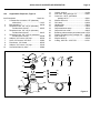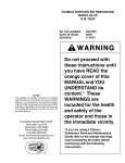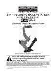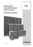
1
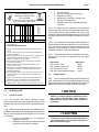
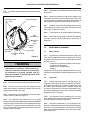
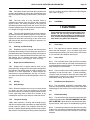
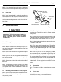
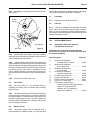
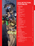
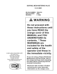
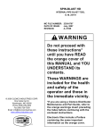
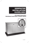
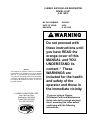
APOLLO 60 HP SUPPLIED-AIR RESPIRATOR
CLEMCO SUPPLIED AIR RESPIRATOR
MODEL 60 HP
O.M. 10533
MC FILE NUMBER:
DATE OF ISSUE:
REVISION:
690-0985
09/85
K, 05/15/98
WARNING
NOTICE
This supplied air respirator conforms to all NIOSH
specifications and standards and carries NIOSH
approval. As manufactured, this respirator complies
only with those foreign approvals that accept NIOSH
certification. Specifically, it has not been manufactured
to European CE standards and does not carry the
European CE-mark.
© CLEMCO INDUSTRIES CORP.
One Cable Car Drive
Washington, MO 63090
Phone (636) 239-4300
Fax (636) 239-0788
®
Do not proceed with
these instructions until
you have READ the
orange cover of this
MANUAL and YOU
UNDERSTAND its
content.* These
WARNINGS are
included for the health
and safety of the
operator and those in
the immediate vicinity.
*If you are using a Clemco
Distributor Parts and Maintenance
Guide refer to the orange warnings
insert preceding the Index before
continuing with the following
instructions.
APOLLO 60 HP SUPPLIED-AIR RESPIRATOR
3.
4.
5.
6.
Periodic training.
Periodic environmental monitoring.
Respirator-fit testing.
Maintenance, inspection cleaning, and
storage of the respirators.
7. Selection of the proper NIOSH-approved
respirator.
Clemco Industries Corp.
Washington, Missouri USA
(314) 239-0300
Hose 100 Ft.
04398
Cautions and
Limitations 2
Hose 50 Ft.
04415
x
Hose 25 Ft.
04397
x
Cont. Flow Conn.
21422
x
Flow Regulator
04411
x
Flow Regulator
04410
x
Flow Regulator
04440
x
x
Helmet
10506
x
SA APL
19C-130
Alternates
Components
MODEL
PROTECTION 1
TYPE C AND CE CONTINUOUS FLOW SUPPLIED-AIR RESPIRATOR IS APPROVED
ONLY IN THE FOLLOWING CONFIGURATIONS:
TC#
B- Not for use in atmospheres immediately dangerous to life or
health.
C-Do not exceed maximum use concentrations established by
regulatory standards.
D-Air-line respirators can be used only when the respirators are
supplied with respirable air meeting the requirements of
CGA G-7.1 Grade D or higher quality.
E- Use only the pressure ranges and hose lengths specified
in the user's instructions.
J- Failure to properly use and maintain this product could
result in injury or death.
M-All approved respirators shall be selected, fitted, used, and
maintained in accordance with MSHA, OSHA, and other
applicable regulations.
N-Never substitute, modify, add, or omit parts. Use only exact
replacement parts in the configuration as specified by the
manufacturer.
O-Refer to users instructions, and/or maintenance manuals for
information on use and maintenance of these respirators.
S-Special or critical users instructions, and/or specific use
limitations apply. Refer to instruction manual before donning.
INTRODUCTION
1.1
Scope of manual
1.1.3 For safe use of the respirator, it is essential that
the user be properly instructed in its use and maintenance.
This manual must be made available to all users of the
respirator. [Reference OSHA Regulations 1910.134.] Read
the entire manual before installing or operating the equipment.
BCDEJNOS
1 PROTECTION
SA-Supplied -air
2 CAUTIONS AND LIMITATIONS
1.0
Page 1
1.1.1 This manual covers setup, operation, maintenance, replacement parts, and important warnings for safe
operation of the Clemco Apollo 60 HP Supplied-Air Respirator.
1.1.2 OSHA requires the employer to establish a comprehensive respiratory protection program per regulations
29 CFR 1910.134(a)(b) and 29 CFR 1926.103, to include
the following:
1. Program coordination by a designated
responsible individual.
2. Evaluation of each worker’s ability to perform
the work while wearing a respirator.
1.1.4 The respirator must be supplied with respirable air
meeting requirements described herein. It is the responsibility of the owner to provide quality breathing-air to the
respirator, and to establish a program to ensure that the
respirator is properly used and maintained.
1.1.5 The following manuals are available for accessories that may be used in conjunction with the Apollo
Respirator.
Description
Manual No.
CAT Cool-Air Tube
08956
CCT Climate Control Tube
08850
CPF Particulate Air Filter
04143
ABL 4021 CarbonMonoxide Alarm
21457
1.2
Hazard Alerts
1.2.1 Clemco uses signal words, based on ANSI Z535.21991, to alert the user of a potentially hazardous situation
that may be encountered while operating this equipment.
ANSI’s definitions of the signal words are as follows:
! NOTICE
“Notice” is used to indicate a statement of company policy as the message relates directly or
indirectly to the safety of personnel or protection
of property.
! CAUTION
“Caution” is used to indicate a potentially hazardous situation which, if not avoided, may result in
minor or moderate injury.
APOLLO 60 HP SUPPLIED-AIR RESPIRATOR
! WARNING
“Warning” is used to indicate a potentially hazardous situation which, if not avoided, could
result in death or serious injury.
! DANGER
“Danger” is used to indicate an imminently hazardous situation which, if not avoided, will result
in death or serious injury.
1.3
Respiratory and Health Alerts
! WARNING
TOXIC DUST POISONING
Research by the Occupational Safety and Health
Administration (OSHA) has discovered potential
risks of lead and other heavy metal poisoning to
unprotected abrasive blasting operators and other
personnel who may be exposed to toxic dust in
the abrasive blasting vicinity. Toxic dust is produced primarily by the removal and breakdown of
lead or other heavy metal coatings during abrasive blasting.
The breakdown of toxic coatings and hazardous
abrasive causes the contaminants to become
airborne. Breathing toxic dust from lead or other
heavy metal coatings may cause health and life
threatening toxic poisoning and can damage vital
organs. Breathing hazardous dust produced from
silica abrasive may cause delayed life threatening respiratory disease such as silicosis.
Lead is one of several toxic dusts that may be
present in an abrasive blasting operation. It is
imperative that blasting contractors identify all
material being removed by blasting, and obtain
material safety data sheets (MSDS) for the blasting abrasive prior to blasting. It is the responsibility of the employer to identify all airborne contaminants in the blast vicinity, and ensure they do
not exceed the permissible exposure limit (PEL)
Ref. 29 CFR 1910.1000 and 29 CFR 1926.62. Thorough examinations should be made by an industrial hygienist or other qualified professional to
identify all contaminants generated by blasting
and in the blasting vicinity.
Exposure to dangerous levels of lead or other
Page 2
toxic or hazardous dust is not restricted to blast
operators. There may be an equal or greater
danger after the blasting process due to lingering
airborne dust particles, and especially from dust
generated during cleanup activity. Heavy metal
paint, asbestos, sand or other silica, and other
toxic material dusts will cause serious lung disease or death without the use of properly designed, and maintained NIOSH-approved, supplied-air respirator equipment by blasting operators and all personnel within the work site area.
Lead poisoning can cause death. OSHA has stated
that the permissible exposure limit of lead is 50
micrograms per cubic meter of air (50 µg/m3),
averaged over an 8-hour workday.
The Apollo supplied-air respirator system is approved by NIOSH as a Type-CE, continuous-flow,
abrasive blast, supplied-air respirator, in accordance with title 42 CFR Part 84. The NIOSH recognized assigned protection factor (APF) for any
supplied-air respirator equipped with a loosefitting hood or helmet and operated in a continuous flow mode is 25, based upon the NIOSH
Respirator Decision Logic (Pub. No. 87-108). In
other words, any Type-CE respirator should be
used only in atmospheres in which the contaminant level does not exceed 25 times the permissible exposure limit. However, in its Memorandum for Regional Administrators dated August
30, 1995, OSHA has stated that select individual
Type-CE continuous-flow, abrasive blast, supplied-air respirator models that pass stringent
tests conducted by independent third party testing laboratories will be granted APF values higher
than the NIOSH recognized 25. Clemco contracted
with Los Alamos National Laboratory to conduct
the independent testing. Based upon the results
of these tests, OSHA will treat the Apollo Supplied-Air Respirator (NIOSH Approval TC-19C130) as having an APF of 1000 times the permissible exposure limit, or 50,000 µg/m3 when used in
lead removal applications.
The employer must provide and maintain appropriate approved respirators, in addition to providing operator training and employing required
work site safety practices.
To avoid any potential danger of respiratory injury, approved, supplied-air respirators must be
worn at all times in the presence of any type of
dust. The respirator must be maintained as described herein. Improper use of any respirator
may cause life threatening respiratory disease,
and immediate poisoning from toxic dust. Respirators should be removed only after the ambient
air has been tested with a dust monitor, and found
to be safe to breathe.
Toxic dust poisoning may also occur by eating,
drinking, or smoking in a contaminated area, or
by eating, drinking, or smoking in a non-hazardous area before thorough washing of hands and
face. Do not eat, drink or smoke in the blast area.
Thoroughly wash hands and face to remove contaminants before eating, drinking, or smoking
outside the blast area.
APOLLO 60 HP SUPPLIED-AIR RESPIRATOR
This manual does not contain all the health and
safety requirements regarding toxic and hazardous dust exposure. Obtain copies of the OSHA
regulations and consult a safety professional
and/or industrial hygienist for complete requirements.
1.5.1 Air pressure at the point of attachment (the point
of attachment is where the respirator supply hose is
connected to the respirable air source) must be maintained at pressures between the minimum pressure as
shown in the table in Section 4.2.4 and the maximum of
100 psi.
Within this manual we refer to hazardous or contaminated environments. These environments can
be any place around the blast area that could
contain toxic or hazardous dust.
If these warnings are not completely understood,
or if further information is required, contact a
local OSHA office. If any personnel in the abrasive blasting vicinity cannot read or comprehend
these warnings and the entire content of this
instructional material, assign a qualified person
to instruct them.
Additional information on abrasive blasting hazards titled “Preventing Silicosis and Death From
Sandblasting”, Publication No. 92-102, is available from:
Publications Dissemination, DSDTT
National Institute for Occupational Safety and Health
4676 Columbia Parkway
Cincinnati, OH 45226 (513) 533-8287
1.4
Cautions and Limitations
1.4.1 Not for use in atmospheres immediately dangerous to life or health.
! WARNING
Failure to maintain the minimum pressure at the
point of attachment may reduce air flow below the
minimum flow required by OSHA. Reduced air
flow may result in ingress of hazardous toxic
dust, subjecting the user to immediate health and
life threatening poisoning and subsequent respiratory disease.
1.5.2 Use no more than 12 sections of respirator hose to
obtain a total maximum length of up to 300 feet, as noted
in the table in Section 4.2.4.
1.5.3 The respirator is designed for specific use in
abrasive blasting applications. Do not use in other operations such as painting or welding.
1.6
1.4.2 Do not exceed maximum use concentrations established by regulatory standards.
1.4.3 Air-line respirators can be used only when the
respirators are supplied with respirable air meeting the
requirements of CGA G-7.1 for Grade D or higher quality.
1.4.4 Use only the pressure ranges and hose lengths
specified in the instruction manual.
1.4.5 Failure to properly use and maintain this product
could result in injury or death.
1.4.6 All approved respirators shall be selected, fitted,
used, and maintained in accordance with MSHA, OSHA,
and other applicable regulations.
1.4.7 Never substitute, modify, add, or omit parts. Use
only exact replacement parts in the configuration as specified by the manufacturer.
Page 3
Protection
1.6.1 Assigned Protection Factor (APF): The NIOSH
recognized assigned protection factor for any Type-CE
respirator (the Apollo respirator is a Type-CE respirator) is
25 times the permissible exposure limit (PEL). In other
words, CE respirators should be used only in atmospheres
in which the contaminant level does not exceed 25 times
the PEL. However, based upon the results of independent
testing, OSHA will treat the Apollo Supplied-Air Respirator
as having an APF of 1000 times the PEL when used in lead
removal applications.
1.6.2 Head: The respirator protects the wearer’s head
and neck from impact and from abrasion caused by rebounding abrasive. The respirator meets physical requirements for industrial head protection as stated in ANSI
Z89.1-1997 as a Type I Class G protective helmet.
1.6.3 Face: The Apollo 60 inner lens meets impact and
penetration requirements under ANSI Z87.1-1989.
1.4.8 Refer to users instructions, and/or maintenance
manuals for information on use and maintenance of these
respirators.
1.6.4 Eyes: Apollo respirators do not provide primary
eye protection. Wear approved eye protection with the
respirator.
1.5
1.6.5 Hearing: Noise generated by the Apollo respirator
and measured inside the helmet do not exceed 80 deci-
Special Use Limitations
APOLLO 60 HP SUPPLIED-AIR RESPIRATOR
bels. (42 CFR part 84.140) When any exterior noise
causes the internal noise level to exceed 80 decibels, the
user must wear additional hearing protection. A variety of
hearing protectors can be worn with the respirator.
1.7
Page 4
1.7.2 The respirator comes with one of four air control
devices that permit safe, comfortable blast cleaning under
various conditions.
• Constant-Flow Connector (CFC): Provides non-adjustable volume of supplied air, within the cfm range required
by OSHA.
Description
1.7.1 The Clemco Apollo 60 Supplied-Air Respirator is
approved by the National Institute of Occupational Safety
and Health (NIOSH).
! WARNING
• Air Control Valve (ACV): Enables the user to a d j u s t
the volume of supplied air, within the cfm range required by
OSHA. It is for use in areas where the air temperature is
comfortable.
• Cool-Air Tube (CAT): Used in warm climates to enable
the user to adjust supplied air to cooler temperatures.
OSHA/NIOSH approval applies only when this
supplied-air respirator is used as a complete
system. Do not make any non-approved modification, deletion, or substitution. Non-approved
components voids the NIOSH approval and may
permit ingress of toxic and hazardous dust, and
result in toxic poisoning and respiratory disease.
• Climate Control Tube (CCT): Enables the user to adjust
supplied air to warmer or cooler temperatures.
1.7.3 Low Pressure Conversion Kit: This optional accessory kit contains parts and instructions to convert the
Apollo 60 HP, (respirator for use with Grade “D” Compressed Air) to Apollo 60 LP (respirator for use with
ambient air pump). The kit is listed in Section 10.1.
Breathing-Air
Tube Assembly
Apollo 60
Supplied-Air
Respirator
General Arrangement
of Operator Safety
and Comfort Components
Carbon
Monoxide
Alarm
Blast
Suit
Climate
Control
Tube
Gloves
Respirator
Supply Hose
Breathing-Air
Source
Blast Suit
CPF-20
Particulate
Filter
Figure 1.
APOLLO 60 HP SUPPLIED-AIR RESPIRATOR
2.0
INSPECTION
! NOTICE
A Clemco respirator hose must be used with the
Apollo Respirator. If one is not available, it must
be ordered from an authorized distributor of
Clemco products. Hoses are not included with
respirators, because blast operators often are
assigned personal respirators, while using common respirator hoses.
3.2.1 The lens system is an important part of the respirator assembly. The helmet is supplied with an inner lens,
secured by a thick rubber gasket. Held in place on top of
the inner lens by the window frame are up to five perforated
outer lenses.
3.2.2
9.1)
Check that the inner lens is in place. (See Section
3.2.3 The perforated outer lenses are secured to the
helmet by the window frame. As one lens becomes frosted
during blasting, it can be torn off to expose the next lens.
Check that the perforated outer lenses are in place. (See
Section 9.2)
3.3
2.1
Page 5
Belt
Component Checklist
2.1.1 Make sure that all the respirator components are
present. Each respirator box should contain the following:
• Helmet with chin strap, suspension and cape
attached
• Breathing tube assembly
• One of the following air control devices with belt:
Constant-Flow Connector
Air Control Valve
Cool-Air Tube
Climate-Control Tube
• Disconnect adaptor assembly
NOTE: Respirator hose (one or more alternate hoses)
must be ordered separately.
3.3.1 Using the spring clip attached to the ConstantFlow Connector, attach the connector to the belt slide. This
step is not required with alternate air control devices,
because the Air Control Valve is furnished with a hook-on
belt clip, and belts are attached to Cool Air Tubes and
Climate Control Tubes.
3.4
3.4.1 Attach the red end of the breathing tube to the
threaded air inlet fitting at the back of the helmet.
3.4.2 Attach the swivel connector on the black end, to
the Constant-Flow Connector, or alternate air control
device.
! WARNING
2.1.2 When all of these components are present, prepare the respirator for operation per Section 3.0.
3.0
PREPARATION
3.1
Adjust Helmet Suspension per Section 6.2.
3.2
Lens Assembly
! WARNING
Never use the respirator without the fixed inner
lens and perforated outer lenses in place. The
fixed lens provides support for the window gasket. If the gasket is not adequately supported,
leaks can occur which could permit entry of toxic
and hazardous dust or abrasive into the helmet.
Breathing Tube Assembly
The red end of the breathing tube must attach to
the helmet, and the black end to the ConstantFlow Connector or alternate air control valve.
Failure to properly attach the tube may increase
noise levels beyond OSHA limits.
3.4.3 Use the strap handle to carry or hang the respirator. Never hold, carry or hang the respirator by the breathing tube. Mishandling the respirator in this manner may
damage the tube or helmet inlet. Any leaks or breaks in the
breathing tube will alter the air flow through the respirator
and affect user’s safety and comfort.
3.5
Respirator Hose
3.5.1 Use the disconnect adaptor assembly to attach
the respirator hose to the Constant-Flow Connector, or
alternate air control device. Using the adaptor provided,
APOLLO 60 HP SUPPLIED-AIR RESPIRATOR
connect the other end of the respirator hose to a respirable
air source. If longer hose is required, it must be a NIOSHapproved Clemco respirator hose extension. Any 25 foot,
50 foot and 100 foot respirator hoses can be added in any
combination to produce the maximum total length as noted
in the table in Section 4.2.4.
4.0
AIR SUPPLY
! WARNING
Air supplied to this respirator system is critical to
the safety of the user. Read this section carefully.
Poor quality air will cause serious respiratory
injury or death to the user. See Toxic Dust Poisoning Warning in Section 1.3.
4.1
Air Quality
4.1.1 The quality of air supplied to the respirator is
extremely critical to the safety of the user. Special care
must also be taken to avoid accidental connection to any
other gas lines; such as, oxygen, acetylene, or nitrogen.
! WARNING
Never connect a breathing air line to an air source
that has not been tested for gas and particulate
contamination. The presence of unacceptable
levels of carbon monoxide (CO) or other gases in
the breathing air will cause death to the user.
! WARNING
Do not use piston type, oil-bath, compressors for
breathing air. These compressors could produce
dangerous levels of carbon monoxide, which will
cause death to the user.
4.1.2 Breathing air used to supply the respirator must be
respirable breathing air and contain no less than 19.5
volume-percent of oxygen. Breathing air shall also meet
the requirements for Grade D or higher quality, as described in Compressed Gas Association Commodity Specification pamphlet G-7.1., titled Commodity Specification
For Air, published by Compressed Gas Association Inc.,
Arlington, VA. (42 CFR Chapter 1).
Page 6
4.1.3 Prior to using the respirator, read the owner’s
manual and all instructions, labels, and warnings relating
to the compressed air source. Take special care to abide
by all warnings from the compressor manufacturer regarding compressor use.
4.1.4 A breathing air type compressor must be used.
The compressor must be equipped with necessary safety
and monitoring devices, plus suitable in-line air filters and
purifying equipment to assure breathing air quality. [Reference OSHA Regulations 29 CFR 1910.134 (d), and 29
CFR 1926.103 (f)].
4.1.5 If an oil-lubricated compressor is used, it must be
equipped with a high-temperature alarm or carbon monoxide (CO) alarm, or both. If only a high-temperature alarm
is used, the air from the compressor must be tested
frequently for the presence of carbon monoxide. [Reference OSHA Regulations 29 CFR 1910.134 (d) and 29 CFR
1926.103 (f)].
4.1.6 Regardless of the air compressor type, precautions must be taken to prevent contaminants from entering
through the compressor intake. The compressor inlet must
be located away from all sources of toxic contaminants
including carbon monoxide, which is found in engine
exhaust, and in any form of combustion. No vehicles
should be allowed near the compressor intake. Contaminants can enter respiratory equipment through the compressor air inlet. This inlet must not be located near any
exhaust system outlet, ventilation flue, or source of fumes
or particles of any kind.
4.1.7 The precautions described above also apply to
portable compressors. In addition, in the case of enginedriven compressors, precautions must be taken to prevent
engine exhaust gases from entering the air intake of the
compressor. Compressor engine exhaust should be piped
to a location safely downwind from the compressor air
intake. Compressors vary in design and operation; therefore, it is important that users carefully read the
manufacturer’s operation and maintenance instructions
before making modifications.
4.1.8 An appropriate air filter must be installed and
regularly maintained to remove objectionable odors, as
well as oil mist, water, pipe scale and other particulate
matter. Refer to OSHA Regulation 1910.94(6). The Clemco
CPF Air Filter complies with the regulation, and provides
the pressure reducing valve referred to in the regulation.
4.1.9 It is the owner’s and user’s responsibility to check
the air supply. This includes the compressor, carbon
monoxide alarms, air filters, and shut-down devices. An
overheated compressor, or one that is in poor mechanical
condition, may produce carbon monoxide. A carbon
APOLLO 60 HP SUPPLIED-AIR RESPIRATOR
monoxide removal or conversion system may also be used
to ensure breathing air quality. The maximum allowable
presence of carbon monoxide in Grade D breathing air is
10 parts per million (ppm).
4.2
Hose Minimum Pressure Setting, psi
Length
CFC ACV
CCT
CAT
25 ft.
65
85
90
90
50 ft.
65
85
90
90
75 ft.
65
85
90
90
100 ft.
65
85
95
95
125 ft.
70
90
95
95
150 ft.
70
90
100
100
175 ft.
70
90
100
100
200 ft.
70
90
100
100
225 ft.
75
95
*
*
250 ft.
75
95
*
*
275 ft.
75
95
*
*
300 ft.
75
95
*
*
Air Volume and Pressure
4.2.1 A pressure regulator and gauge must be installed
at the point where the respirator hose is attached to the air
source. The Clemco CPF Filter with regulator meets this
requirement if the inlet pressure does not exceed 125 psi.
See typical installation, Figure 1.
! DANGER
Do not connect the Apollo Respirator or CPF
Filter, or any other regulator or filter, to bottled air
that does not have a pressure reducing valve that
reduces pressure to maximum of 125 psi (65 to
100 psi for the respirator only). Failure to comply
with this warning will cause devices rated at
lower pressures to explode under the high pressure of bottled air. Such an explosion could cause
severe injury or death.
4.2.2 The respirator must be supplied with 15 cfm (cubic
feet per minute) of Grade D breathing air at 65 to 100 psi
(pounds per square inch). When using an alternate CoolAir Tube or Climate Control Tube, the respirator must be
supplied with 20 cfm of Grade D breathing air at 90 to 100
psi.
4.2.3 The pressure regulator must be adjusted to 65 to
100 psi. Refer to the table in Section 4.2.4 to determine the
minimum pressure, based on the total length of respirator
hose, and choice of air control device. Adjust the pressure
with the respirator hose and respirator attached. If the
regulator is adjusted with static pressure (no air flow),
pressure may drop below the required pressure when the
respirator is connected, and may result in low air flow.
Setting the pressure as instructed will provide a minimum
of 7 cfm to the respirator.
4.2.4 Use the table below to determine the minimum
pressure setting and maximum respirator hose length,
based on the air control device as shown in Section 1.7.2.
Page 7
* Do not use these control devices at distances greater
than 200 ft.
! WARNING
The compressor must provide adequate output,
and the plumbing between the compressor and
the point of attaching the respirator hose must
have sufficient capacity to supply the volume of
air at the pressure required (as stated in Section
4.2.2). Restricted air flow will cause discomfort to
the user, and may result in ingress of hazardous
and toxic dust, subjecting the user to health and
life threatening toxic poisoning and long term
respiratory disease and death.
5.0
OPERATION
! WARNING
With the respirator on, leave the blast area
immediately if any of the following conditions
occur:
• Any part of the respirator system becomes
damaged.
• Any air monitoring alarm is activated.
• Airflow into the respirator is reduced or
stops.
• Breathing becomes difficult.
• At the first sign of dizziness, nausea, fever,
illness or injury.
• Any contamination is noted by taste, smell
or vision inside the respirator.
• Vision becomes impaired.
• Any irritation is noted.
APOLLO 60 HP SUPPLIED-AIR RESPIRATOR
Page 8
5.1
Prior to operation, thoroughly inspect and clean
the helmet, breathing tube, respirator hose, air entry ports,
and fittings of all dust and debris. Inspect the helmet
suspension and adjust if necessary per Section 6.2.
5.11
When finished blasting and with cleanup, remove
the respirator in a clean, non-hazardous environment
where the air is safe to breathe.
5.2
Start the compressor and open the service valve
to pressurize the air supply line.
! WARNING
5.3
Check air pressure at the point of attachment. Set
the pressure between the minimum pressure assigned in
Section 4.2.4 and the maximum of 100 psi. Pressure must
be set with the respirator connected.
Do not put the respirator on, or store it in a blast
contaminated environment. Do not remove the
respirator in a contaminated environment except
for emergency evacuation when the use of the
respirator hinders escape.
5.4
Check all safety, and breathing equipment used in
conjunction with the respirator as recommended by the
manufacturer.
5.5
Check respirator hoses and connections for tightness and leaks.
5.6
Put the respirator on in a clean non-hazardous
environment, free of contaminants, where the air is safe to
breathe. When putting the respirator on or taking it off,
keep it upright to prevent dust and abrasive from falling
inside.
6.0
ADJUSTMENTS
6.1
Air Control Valve, alternate, Figure 2
Outlet End
(top of unit)
5.7
Position the chin strap so it fits comfortably under
the chin.
5.8
Position the knit cuff on the inner collar so that it fits
snugly around the neck in turtleneck fashion, without any
interference from clothing such as shirt collars. When
correctly positioned the smaller elastic end of the collar
must face up.
! WARNING
Correct placement of the inner collar is critical for
providing the protection for which the respirator
is designed. The collar must be positioned and
maintained without any interference from items
such as hair, facial hair, or shirt collars, between
the collar and user’s neck.
5.9
Pull the cape down to fully extend it and connect
the four elastic straps (two on each side) under the arms,
and tighten using the slides provided.
5.10
Put the belt and control valve on over the cape.
Buckle the belt around the waist, and tighten it by pulling
the belt end through the buckle insert.
Belt Clip
Pull sleeve down
and turn
to adjust air flow
Higher
Adjustment
Sleeve
Lower
Inlet End
(bottom of unit)
Figure 2.
6.1.1 Clemco’s Air Control Valve allows the user to
increase or decrease the volume of breathing-air while
wearing the supplied-air respirator. The valve provides a
range of 7 to 10 cfm of breathing-air when it is supplied with
respirable air as noted in Section 4.0. To regulate the air
supply, pull down and turn the large sleeve on the lower
end of the valve in the desired direction to increase or
decrease the air flow as needed. A soft hissing sound is
normal when the air control valve is in operation as some
air is allowed to escape underneath the sleeve to prevent
the entry of dust into the adjustment mechanism.
APOLLO 60 HP SUPPLIED-AIR RESPIRATOR
6.2
Helmet Suspension Adjustment and Replacement,
Figure 3
White Plastic Tabs
(rear)
Suspension Strap
Button A
6.2.5 Fasten the vinyl sweatband onto the buttons of the
suspension.
6.2.6 Install the suspension strap before installing the
suspension. Insert the yellow end tabs into the clefts on the
helmet shell. When correctly installed, the strap is between
the suspension and helmet shell and above the ears.
6.2.7 Install the suspension by inserting the four white
plastic tabs into the clefts on the shell. The tabs must fully
seat in their respective locators.
6.2.8
Vinyl
Sweatband
White Plastic
Tabs
(front)
Head Band
Tongue
Headband
Size Slots
Front Holder
Front Band Button B
Lugs
Figure 3.
! WARNING
The suspension maintains a fixed distance between the head and the helmet. It is critical that
the suspension is properly installed, and adjusted as described, to provide maximum head
protection and comfort.
Remove the cape from the helmet per Section 9.4.
6.2.2 Remove and discard the old suspension and
suspension strap by extracting the plastic tabs from the
wedge-shaped clefts in the shell.
6.2.3 Unfasten the vinyl sweatband from the two lower,
outside buttons (A and B in Figure 3).
6.2.4 The suspension fits head sizes 6.5 to 8. Head
sizes are marked on the headband slots. Slide the headband
tongue through the front holder until the desired head size
is reached. It is important that the adjustment be made
evenly on both sides. Press the selected slots firmly onto
the lugs on the front band.
Try the helmet on for fit and readjust if necessary.
6.2.9 Check that the chin strap is in place, then reattach
the cape onto the helmet following the instructions in
Section 9.4.
7.0
MAINTENANCE PROGRAM
7.1
Basic Service
7.1.1 A program for maintenance and care of the respirator must be established based on application, working
conditions, and hazards involved, and include the following basic service.
• Inspection for defects (including a leak check)
• Cleaning and disinfecting
• Repair (service maintenance)
• Storage
Equipment must be properly maintained to retain its original effectiveness. [Reference OSHA Regulations 1910.134
(f)].
7.2
6.2.1
Page 9
Inspection
7.2.1 Inspect respirators before and after each use.
Inspection shall include a check for tightness of connections and the condition of the lenses, suspension, cape
and elastic parts, breathing tube, respirator hoses and
connectors, Constant-Flow Connector or alternate air control valve or temperature control valve. [Reference OSHA
Regulations 1910.134 (f)(2)].
7.2.2 The respirator hoses, breathing tube, air entry
ports, and fittings must be checked for dust contamination,
and cleaned before making connections.
7.2.3 The helmet suspension is a very important component for maintaining maximum hard hat and respiratory
protection. It must be inspected for fit and wear on a daily
basis, and replaced immediately at the first sign of wear.
(See Section 6.2)
APOLLO 60 HP SUPPLIED-AIR RESPIRATOR
7.2.4 Periodically inspect and clean the foam filter and
screen in the alternate air control valve. Replace the foam
filter at first sign of blockage or deterioration. (See Section
9.8)
7.2.5 The inner collar is a very important factor in
controlling air escape from the helmet and preventing
ingress of dust. The elastic properties of the collar are
intended to provide a snug fit on the user’s neck. The collar
must be replaced before it is stretched to the point where
it no longer fits snugly around the neck.
7.2.6 The outer cape provides protection from rebounding abrasive and from abrasive ingress into the helmet.
Inspect the outer cape frequently for wear. Replace the
cape before holes are worn through, or any wear occurs
that prevents the cape from providing the protection for
which it is intended.
7.3
Cleaning and Disinfecting
7.3.1 Respirators must be cleaned and disinfected as
frequently as necessary to ensure that proper protection is
provided to the wearer. Respirators used by more than one
person must be cleaned and disinfected after each use.
See Section 8.0 for cleaning instructions. [Reference
OSHA Regulations 1910.134 (b)(5); 1910.134 (f)(3)].
7.4
Repair (Service Maintenance)
7.4.1 Replacement or repairs shall be done only by
trained persons, using genuine Clemco parts designed for
the respirator. No attempt shall be made to replace components or to make adjustment or repairs beyond the
manufacturer’s recommendations. See Sec. 9.0 for service instructions. [Reference OSHA Regulations 1910.134
(f)(4)].
Page 10
store it in a clean, dry place. [Reference OSHA Regulations 1910.134 (f)(5)].
8.0
CLEANING
! CAUTION
Follow washing instructions as described in this
section. Do not use any caustic chemicals or
solvents that may be irritating or harmful to the
user, or which change the properties of the materials used in any part of the respirator.
8.1
Outer Cape
8.1.1 The cape can be machine washed using warm
water and mild detergent. Dry in a clothes dryer at the
lowest temperature setting. Do not dry clean. See Section
9.4 for removal and installation instructions.
8.2
Inner Collar
8.2.1 The removable inner collar should be frequently
washed to remove build-up of dirt that accumulates from
normal perspiration and air moisture. For general hygiene,
daily washing is recommended.
8.2.2 The inner collar may be either washed or replaced
separately or with the outer cape. To wash separately,
unzip the collar and machine wash with warm water and
mild detergent. Tumble dry in a clothes dryer at the lowest
temperature setting. Do not dry clean.
7.5
Storage
8.3
7.5.1
Daily Storage
8.3.1 The sweatband, suspension, suspension strap,
and chin strap should be washed using warm water and
mild detergent. See Section 6.2 for removing the suspension.
7.5.1.1 When the respirator is not in use, it must be stored
in a clean, dry area. Hang the respirator by the strap
provided on the top. Do not tuck the cape inside the helmet.
Let the cape hang loose to allow air to circulate, to dry
condensation from the cape and from inside the helmet.
7.5.2
Long-term storage
7.5.2.1 After inspection, cleaning and thorough drying,
and after necessary repairs are made, the cape should be
tucked inside the helmet. The respirator shall then be
placed in a plastic bag and the bag sealed to keep out dust
and moisture. Place the bag in a clearly marked carton and
8.4
Sweatband and Suspension
Helmet Assembly
8.4.1 The helmet assembly should be wiped clean with
mild detergent and water. DO NOT IMMERSE THE HELMET IN WATER! While this does not permanently damage the helmet, it will require an extended drying period.
8.4.2 Care must be used to prevent abrasive entry when
putting on or removing the respirator and when changing
lenses. Vacuum the inside of the helmet to remove any
abrasive.
APOLLO 60 HP SUPPLIED-AIR RESPIRATOR
8.4.3 If the acoustical foam on the inside of the helmet
becomes soiled, it can be wiped with a damp cloth or pulled
off and replaced.
Page 11
Locating Tabs
Perforated Outer Lens
8.5
Inner Lens
Lens Pull Tab
Window Frame
8.5.1 Inner lenses should be replaced when dirty or
scratched; however mild detergent and water can be used
to clean the inner lens. Volatile solutions such as alcohol,
gasoline or ammonia must not be used to clean this lens.
Allow the lens to air dry; cloth and towels can scratch the
lens surface.
Inner Lens
Hinge
Lens Replacement
9.0
SERVICE MAINTENANCE
! CAUTION
Clean the respirator of dust and media before
maintenance. All maintenance must be done in a
clean environment away from dust and media.
Doing so will help prevent ingress of dust and
contaminants.
9.1
Replacing Inner Lens
9.1.1
Unlatch and open the window frame.
9.1.2 Working from inside the helmet, pull up the window gasket lip and push the gasket and lens out the front
of the window opening.
9.1.3 Remove the old lens from the gasket and replace
with new lens.
9.1.4 Place the new lens and gasket over the window
opening. From the inside of the helmet, work the gasket lip
back onto the helmet.
9.1.5 Smooth out wrinkles in the gasket on the inside of
the helmet.
9.1.6 To maximize the wear life of the inner lens do not
remove the last perforated outer lens. (See Section 9.2)
The respirator must never be used without the inner lens
in place.
9.2
Replacing Perforated Outer Lenses, Figure 4
9.2.1 Up to five outer lenses can be installed at one time.
For maximum visibility, install only enough lenses to last
during a work period.
Inner Lens Gasket
Figure 4.
9.2.2 Preparing lenses in the following manner will
permit lenses to be pulled off easily by a user wearing
heavy gloves.
9.2.3 Place up to five lenses on a clean flat surface. Fold
up the tab of each lens except the first and last, so that the
tab of each lens is against the back of the one over it.
9.2.4 Unlatch and open the window frame and remove
all remnants of old lenses.
9.2.5 Pick up the stack of prepared lenses. They will be
installed with the straight side toward the top of the helmet,
and the pull tabs toward the hinged end of the window
frame. See Figure 4.
9.2.6 Drop only the top lens tab through the window
frame opening at the window frame hinge end. The tab of
the bottom lens (inside lens) should not go through the
window frame opening. Placing the lenses in this manner
will prevent unintentional removal of the last perforated
lens and prolong the life of the inner lens. Allow all the
lenses to drop in place between the locating lugs on the
window frame. The lens perforations should line up close
to the window frame opening when the frame is closed and
latched.
9.3
Suspension
9.3.1
6.2.
To replace and adjust suspension, see Section
9.4
Outer Cape
9.4.1 When the cape becomes soiled or requires replacement, it can easily be removed as follows.
APOLLO 60 HP SUPPLIED-AIR RESPIRATOR
9.4.2 Separate the Velcro tabs on the back of the cape.
See Figure 5.
Air Inlet
Fitting
closed. When replacing the window frame the acoustical
foam inside the helmet should also be replaced.
9.7
Chin Strap
9.7.1
Replace the chin strap when worn.
9.8
Filter Kit
9.8.1 A filter kit is available for the alternate Air Control
Valve. When the foam filter becomes soiled or deteriorates, pry out the retaining ring with a small screwdriver.
Remove the screen and dirty filter. Replace all three items
with parts supplied in the kit.
Notch
Cape Removal
Velcro Tab
Figure 5.
9.4.3 Slide the ends of the cape to the notch. Continue
sliding one end of the cape out of the groove until the entire
cape is detached from the helmet.
9.4.4 To install the cape, separate the Velcro tabs on the
cape and slide one end into the groove on the bottom edge
of the cape attachment strap at the point where the groove
is notched. Continue sliding the cape around the bottom of
the helmet until the entire cape is completely into the
groove. NOTE! Spraying a non-toxic silicone-base lubricant into the groove will reduce friction and ease assembly.
9.4.5
Join the Velcro tabs at the notch.
9.5
Inner Collar
9.5.1 The inner collar is a very important factor in
controlling air escape from the helmet and preventing
ingress of dust.
9.5.2 The elastic properties of the collar are intended to
provide a snug fit on the user’s neck. The inner collar must
be replaced before it is stretched to the point where it no
longer fits snug against the neck. The collar unzips from
the outer cape for replacement or washing. See Section
8.2 for cleaning instructions.
9.6
Page 12
Window Frame
9.6.1 The window frame must be replaced when it
becomes difficult to maintain a seal, or to keep the latch
10.0
REPLACEMENT PARTS
10.1
Supplied-Air Respirator Systems
and Alternate Accessories
Respirators do not include alternate respirator
hoses shown in Section 10.2. Respirator hose must
be ordered separately.
Item Description
(-)
(-)
(-)
(-)
(-)
(-)
(-)
(-)
(-)
Stock No.
Apollo 60 HP Respirator,
w/constant-flow connector ................. 21300
Apollo 60 HP Respirator,
w/air control valve .............................. 10505
Apollo 60 HP Respirator,
w/cool-air tube ................................... 10508
Apollo 60 HP Respirator,
w/climate control tube........................ 10509
Air control valve with belt ......................... 04440
Cool-air tube with belt .............................. 04410
Climate control tube with belt .................. 04411
Filter kit, air control valve ......................... 04381
Low pressure conversion kit.
Converts Apollo 60 HP (high pressure)
(Grade “D” Compressed Air)
respirator to LP (low pressure,
ambient air) respirator ....................... 22079
Page 13
APOLLO 60 HP SUPPLIED-AIR RESPIRATOR
10.2
11.
12.
13.
Supplied-Air Respirator, Figure 6
Item Description
Stock No.
1.
Constant-flow connector, HP (alternate),
without belt ........................................ 21415
2.
Belt assembly, 2" ..................................... 04430
3.
Respirator hose, 3/8" x 25 ft. (alternate),
includes items 6 and 7 ....................... 04397
4.
Respirator hose, 3/8" x 50 ft. (alternate),
includes Items 6 and 7 ...................... 04415
5.
Respirator hose, 3/8" x 100 ft. (alternate),
includes items 6 and 7 ....................... 04398
6.
Adaptor, 3/8" hose to 3/8" pipe ................ 00022
7.
Union, 3/8" hose to 3/8" hose .................. 01020
8.
Disconnect, 1/4" female ........................... 00025
9.
Adaptor, 3/8" hose to 1/4" pipe ................ 01019
10.
Acoustical foam kit, sides ........................ 04369
(16)
Gasket, window ........................................ 04452
Inner lens, .040" package of 5 ................. 04367
Outer lens, .0075", perforated,
package of 25 .................................... 04361
Window frame kit ..................................... 08741
Chin strap ................................................. 04460
Handle strap ............................................. 03623
Suspension .............................................. 10532
Cape attachment strap ............................ 10534
Cape with inner collar .............................. 04435
Breathing tube assembly w/molded ends 21550
Washer, breathing tube, package of 6 ..... 04370
Inner collar kit........................................... 08740
Window latch kit ....................................... 04368
O-Ring, .864" ID x 1.004" OD .................. 21561
14.
15.
16.
17.
18.
19.
20.
21.
22.
23.
24.
(10)
(23)
(18)
(17)
(24)
(11)
(15)
(12)
(13)
(14)
(8)
(9)
(22)
(6)
(20)
(2)
(19)
(21)
(1)
(3, 4, 5)
(7)
Figure 6.