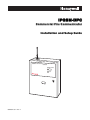
1
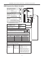
IPGSM-DPC Commercial Fire Communicator Installation and Setup Guide IPGSM-DPC Commercial Fire Communicator RADIO TROUBLE LOW BATT AC LOSS AC ON 800-09370 6/11 Rev. A Contents General Information .......................................................................................................................1 Package Contents .......................................................................................................................1 Compatible Fire Panels ..............................................................................................................1 Operation .........................................................................................................................................2 Installation ......................................................................................................................................3 ULC Compliance .........................................................................................................................3 STEP 1 – Setup the Customer Account.....................................................................................3 STEP 2 – Register the Communications Module with AlarmNet ...........................................3 STEP 3 – Determine the Signal Strength and Select a Location ............................................4 STEP 4 – Mount and Wire .........................................................................................................4 Wiring the 659EN Line Fault Monitor (if required) ............................................................7 STEP 5 – Program the Communications Module .....................................................................8 STEP 6 – Configure the Fire Panel ...........................................................................................9 STEP 7 – Test the System..........................................................................................................9 Dialer Capture Module Information ............................................................................................10 LED Display Information .............................................................................................................10 PowerBoost1 Module Information................................................................................................11 iGSM Communications Module Information ..............................................................................12 RF Specifications ......................................................................................................................13 Central Station Messages.............................................................................................................13 IPGSM-DPC Trouble Detection Information ..............................................................................14 IPGSM-DPC Specifications ..........................................................................................................14 Wiring Diagram.............................................................................................. Inside of Back Cover IPGSM-DPC Commercial Fire Communicator – Installation and Setup Guide General Information The IPGSM-DPC Commercial Fire Communicator (henceforth referred to as IPGSM-DPC) includes everything you need to upgrade a commercial fire system that previously reported by POTS to a system that uses the Internet as its primary reporting path, and uses a GSM cellular reporting path as a backup. In addition, this communicator utilizes a sophisticated power module (PowerBoost1) that monitors and reports AC power loss, low battery, and missing battery conditions. Package Contents Red Fire Cabinet and Back Plate Antenna and Mounting Adapter Mounting Rails (for above) Cam Lock with Key PowerBoost1 Hardware Bag Dialer Capture Module Battery harness/fuse (# 100-02415) Transformer, 18VAC iGSM Communications Module Ferrite Filter 50 ohm cable assembly LED Display board (# 1451-UL9) Compatible Fire Panels The IPGSM-DPC works with: All Fire Panels that are listed in the table below. All Fire Panels that use the Contact ID communication format as described in the SIA DC-05 Standard. IMPORTANT: For a fire panel that has more than 9 active partitions, the first 9 partitions are reported to the central station uniquely. Beyond 9 partitions, only the 2nd digit of the partition is reported along with a leading zero (example partition 14 is reported as 04). The installer must inform the central station of this condition. The IPGSM-DPC is compatible with the Honeywell brand FACP’s listed below when the model 659EN Line Fault Monitor is installed. Honeywell Fire Panel Communicator Honeywell Fire Panel Communicator 411 family two MS-9600LSC-FR 411UD family two 411UDAC family two family three Use the DACT-UD2 product to interface the IPGSM-DPC. FireWarden-100-2C family three NFS2-3030 family one (requires UDACT) FireWarden-100-2C-FR family three FireWarden-50C family two FireWarden-50C-FR family two MS-10UD-7C family three MS-10UD-7C-FR family one (requires UDACT) MS-25C family four MS-5UD-7C family three MS-5UD-7C-FR family one (requires UDACT) MS-9050UDC family two MS-9050UDC-FR family two MS-9200UDLSC family three MS-9200UDLSC-FR family three MS-9600LSC family three Use the DACT-UD2 product to interface the IPGSM-DPC. –1– NFS2-3030-FR family one (requires UDACT) NFS2-640 family one (requires UDACT) NFS2-640-FR family one (requires UDACT) NFS-320 family one (requires UDACT) NFS-320C family one (requires UDACT) NFS-320C-FR family one (requires UDACT) NFS-320SYS family one (requires UDACT) NFS-320SYS-FR family one (requires UDACT) NSP-25C family four SFP-10UDC family three SFP-10UDC-FR family three SFP-5UDC family three SFP-5UDC-FR family three IPGSM-DPC Commercial Fire Communicator – Installation and Setup Guide Operation The IPGSM-DPC replaces the fire panel's POTS communications path. When an event occurs, the fire panel goes off-hook to dial the central station. The IPGSM-DPC detects the off-hook condition and provides the fire panel with a dial tone. When the fire panel detects the dial tone, it begins dialing the central station. The IPGSM-DPC considers the three second period after dialing as the number dialing has been completed. After the dialing is completed, the Dialer Capture Module returns a handshake to the fire panel. The fire panel then sends the contact ID reports to the IPGSM-DPC, which in turn sends a kiss-off after the report is successfully received from the fire panel. Within the IPGSM-DPC, the Dialer Capture Module sends the contact ID reports over the ECP bus to the iGSM Communications Module. When all the reports are sent, the fire panel goes on-hook. The IPGSM-DPC then transmits the messages to the central station (either over the internet or the GSM network). –2– IPGSM-DPC Commercial Fire Communicator – Installation and Setup Guide Installation ULC Compliance To meet Canadian ULC compliance, ensure the following: IPGSM-DPC must be installed in accordance with Canadian Electrical Code, Part 1. IPGSM-DPC must be mounted in the same room and within 20 feet of the fire panel. The wiring must be routed through conduit. IPGSM-DPC, and all equipment used for the IP connection (such as the router, hub, modem, etc.) shall be listed, must be powered from an un-switched branch circuit, and be provided with appropriate standby power. IPGSM-DPC must use a 7AH battery (not supplied) to provide 24-hour backup capability. STEP 1 – Setup the Customer Account The communicator requires a subscriber account (customer account) to be setup with AlarmNet Direct. This is accomplished by registering the communicator's iGSM communications module with AlarmNet. Registering, enables the fire panel to send reports. To setup the customer account you will need to contact the central monitoring station to get account information, and have access to the AlarmNet Direct website. To access the AlarmNet Direct website visit – https://services.alarmnet.com/AlarmNetDirect If you do not wish to use the AlarmNet Direct website, you may call AlarmNet to setup the account, just phone 800-222-6525, then select option 1. (Monday–Friday 8:00 am to 9:00 pm, Saturday 9:00 am to 5:30 pm EST) Have the following information ready: Primary City ID (two digits), obtained from your monitoring station. Primary Central Station ID (two digits), obtained from your monitoring station. Primary Subscriber ID (four digits), obtained from your monitoring station. Communication Module's MAC ID, and MAC CRC number located on outside of box, and inside of the module. Note: The SIM supplied for the IPGSM-DPC is already activated. Therefore no SIM activation is necessary. STEP 2 – Register the Communications Module with AlarmNet Registering the module activates the account with AlarmNet and enables the fire system's control panel to send reports. There are three methods that can be used to register the communications module. Register the module by logging into AlarmNet Direct and choosing “Show Programmed Devices GSM/I”. Search for the account using the Account Information or MAC ID. Under the “Actions” column, use the pulldown menu and choose Register. OR After the IPGSM-DPC is installed and programmed, you can register the module by clicking the Tamper Switch 3 times. OR After the IPGSM-DPC is installed and programmed, you can register the module using the 7720P Programming tool. Simply: Press [Shift ] then press []. Please wait for "Registration SUCCESS" message. –3– IPGSM-DPC Commercial Fire Communicator – Installation and Setup Guide STEP 3 – Determine the Signal Strength and Select a Location IMPORTANT - Do Not mount this device outdoors. RF Exposure Warning – The antenna(s) used for this transmitter must be installed to provide a separation distance of at least 20 cm from all persons and must not be collocated or operating in conjunction with any other antenna or transmitter. When choosing a suitable mounting location, understand that signal strength is very important for proper operation. For most installations using the supplied antenna, mounting the unit as high as practical, and avoiding large metal components provides adequate signal strength for proper operation. In this procedure, you will use the iGSM Communications Module to determine signal strength in order to find a suitable mounting location. Note: Since the SIM is already activated, the RSSI signal strength indicators will indicate signal strength. 1. You will need a fully charged 12V battery. 2. Attach the Antenna (see illustration on page 6). 3. Temporarily wire the battery's negative [–] terminal to TB1–4 on the iGSM communications module, then wire the battery's plus [+] terminal to TB1–2 on the communications module. Wait about one minute for the module to initialize. 4. Position the assembly near a suitable mounting position and observe the RSSI display. 5. Look for a mounting position that yields at least 3 bars lit solid. Four or five bars are better. 3 BARS MIN. R Y Y G G G 7845i-GSM-025-V0 6. Verify the signal strength remains steady for a few minutes, then mark that mounting position. Disconnect the battery. STEP 4 – Mount and Wire For ULC compliant installations, refer to the topic on ULC Compliance in this manual. For Dry/Indoor use only. External cabinet wiring MUST be routed in conduit. This communicator comes partially assembled with all the components mounted except the Antenna, LED Display board, and PowerBoost1. To protect certain components on the PowerBoost1, it is shipped unmounted but fully wired. Note: Refer to the diagram on page 6, and to the Wiring Diagram on the inside of the back cover of this manual for wiring and component identification. 1. Remove knockouts from cabinet to accommodate the power input wires, and wiring to the control panel. (DO NOT REMOVE the two knockouts directly above the PowerBoost1 module.) Then mount the cabinet securely to the wall using 4 screws or bolts. Use mounting screws or bolts that are suitable for the material being anchored to. 2. Ensure the cabinet door lock is installed. 3. Install the two plastic mounting rails for the LED Display board. They simply snap into the back plate holes. –4– IPGSM-DPC Commercial Fire Communicator – Installation and Setup Guide 4. Connect the LED Display board to its connector, then slide the board into the mounting rails. (Refer to the “LED Display Information” topic if a wire is detached from its connector.) 5. Carefully remove the packaging material that surrounds the PowerBoost1. 6. Mount the PowerBoost1 on the three unused standoffs. Use the plastic screw (prevents shorting) to secure the upper right corner of the PowerBoost1 and the two metal screws and lock washers to fasten the left side of the circuit board. Ensure the lock washers are located between the circuit board and the head of the two metal screws. 7. Use the 1451-UL9 Wired Transformer directly connected to un-switched facility power. Connect and route 14AWG (minimum) insulated wire from facility ground to the 1451-UL9 enclosure ground post and through the conduit to the IPGSM-DPC cabinet ground post. 8. Route 16AWG wire from the transformer secondary, through the conduit. Pass the wires through the Ferrite Filter, then loop the wires back through again making a loop. (Ensure the wire ends that connect to the PowerBoost1 Module are tinned.) Connect the wires to the PowerBoost1 AC terminals. At this time DO NOT apply power. 9. Ensure all ground connections are tight. 10. Connect the Ethernet cable and the Telco 1 and Telco 2 lines. If you choose to use an optional Cabinet Tamper Switch (if the control panel supports it) mount and wire it. Note: The Ethernet cable, Telco 1, Telco 2 lines, and the optional cabinet Tamper Switch (if used) must be run through conduit. 11. Verify the PowerBoost1 module DIP switches are configured as shown below. PowerBoost1 ON 1 2 3 4 5 iPGSM-COM-008-V0 ON (Switch handle = white) 1 2 3 4 5 12. Ensure the following: LED Display board is fully seated. All wiring terminals and connectors are tight. All wiring has been completed and secured with cable ties. 13. Install the battery (not supplied). Apply power to the 1451-UL9 Wired Transformer, and attach the battery cable. –5– IPGSM-DPC Commercial Fire Communicator – Installation and Setup Guide ANTENNA 1451-UL9 WIRED TRANSFORMER WIRES MUST BE RUN IN CONDUIT TO 24 HR FACILITY POWER NUT, WASHER BLU BLU 120VAC, 60Hz, 850mA GND POST ANTENNA MOUNTING ADAPTER 18 VAC 72 VA TO Cabinet Ground Post GND BLU TO PowerBoost1 BLU DO NOT REMOVE these knockouts. Tin wire ends. Data Out Data In 12V In GND ZN+ PWR GND Tip 1 Ring 1 ON 1 2 3 4 5 RED GREEN Dialer Capture Module FOR EXTERNAL ANTENNA 50 OHM MMCX ONLY Power Boost1 Module Telco 2 Telco 1 Data Out ECP Tip 2 Ring 2 ZNEOL EOL CABINET DOOR 7720P PROGRAMMER PORT NOT FOR TELEPHONE SERVICE USE! FCC:XXXXXXXXXX BATTERY M1 M0 IBS RSSI GPRS TB 1 1 2 3 4 5 6 7 8 9 10 11 IC: YYYYYYYYYY FUSE PN: 100-02415 + CONDUIT BATTERY 7AH iGSM Comm Module Wiring for Grounds, Power, and RF –6– (not supplied) IPGSM-DPC-001-V1 TO Facility Ground PRIMARY POWER: 9 - 16.5 VAC CURRENT: 900mA PEAK, 70mA STANDBY BATTERY: 8V. 3.1 AHr FOR 24 Hr BACKUP IPGSM-DPC Commercial Fire Communicator – Installation and Setup Guide Wiring the 659EN Line Fault Monitor (if required) The IPGSM-DPC is compatible with the Honeywell brand FACP’s listed on page 1 when the model 659EN Line Fault Monitor is installed. 1. Refer to the installation guide for the 659EN. 2. Mount the 659EN on the lower left side of the IPGSM-DPC cabinet. 3. DO NOT cut the 659EN’s BLACK Output Relay Jumper or the BLUE Voltage Trip Threshold Jumper. 4. Complete the interface wiring as shown below: YEL to Dialer Capture Module, Terminal, Tip 2 ORG to Dialer Capture Module, Terminal, Ring 2 RED to Power Boost 1, Terminal, OUTPUT 1, DC+ BLK to Power Boost 1, Terminal, OUTPUT 1, DC- GRN to Power Boost 1, Terminal, ERTH GND 659EN IPGSM-DPC-013-V0 Wire to a Zone on the Fire Panel 4.7K, 1/2 watt IPGSM-DPC Example wiring for an addressable fire control panel: FIRE LITE Addressable Fire Alarm Control Panel MS-9050UD IPGSM-DPC Commercial Fire Communicator YEL to Dialer Capture Module, Terminal, Tip 2 ORG to Dialer Capture Module, Terminal, Ring 2 RED to Power Boost 1, Terminal, OUTPUT 1, DC+ BLK to Power Boost 1, Terminal, OUTPUT 1, DC- GRN to Power Boost 1, Terminal, ERTH GND - To next device + on SLC Loop TOP MMF-300A Monitor Module T11 T10 T9 T8 T7 5 6 7 8 9 10 11 T6 34 12 2 13 1 0 15 14 TENS 789 56 4 3 2 10 T1 T2 T3 T4 T5 ONES LOOP 659EN Braided-shield/Drain Wire ADDRESS 4.7K, 1/2 watt B+ B- Shield TB5 TB2 B+ A+ B- A- A SLC Loop B NO NC C RELAY 1 ALARM CONTACTS IPGSM-DPC-014-V0 –7– IPGSM-DPC Commercial Fire Communicator – Installation and Setup Guide STEP 5 – Program the Communications Module You must use the 7720P Programming tool to program the IPGSM-DPC. When using the 7720P Programming tool, the values given below are for most installations. Press the [#] key to accept the displayed default value (xxx) or enter the new value and press the [#] key for the next prompt. Use the [Space] key to scroll through a list of options. 1. 2. 3. 4. 5. 6. 7. 8. (no display) 7720P PROGRAMMER Strt Prog Mode? Y/N Program Device? Y/N Com Path Choice (IP&GSM) Primary City ID (??) Primary CS ID (??) Primary Sub ID (????) Connect the 7720P. Press [#]. Press [Shift] then [Y], then [#]. Press [Shift] then [Y], then [#]. Press [Space] to scroll choices; IP&GSM, IP, or GSM. At choice, press [#]. Enter number 01-99, then press [#]. Enter number 01-FE, then press [#]. Enter number 0001-9999, then press [#]. Note: If a Com Path Choice of IP&GSM or IP was selected, prompt 9 will appear. 9. Use DHCP? Y/N (Y) If your router is configured for DHCP, press [Shift] then [Y], then press [#]. Note: If DHCP is not selected (your router is set for a static IP), prompts 10 through 13 will appear. 10. NIC IP Address: 255.255.255.255 Enter choice, then press [#]. Follow the prompts. 11. Subnet Mask: 255.255.255.255 Enter choice, then press [#]. Follow the prompts. 12. Gateway IP Address: 255.255.255.255 Enter choice, then press [#]. Follow the prompts. 13. DNS Serv IP Addr: 255.255.255.255 Enter choice, then press [#]. Follow the prompts. 14. 15. 16. 17. Review? Y/N Create Password? Y/N Exit Prog Mode? Y/N Enter choice, then press [#]. Follow the prompts. Enter choice, then press [#]. Follow the prompts. Press [Shift] then [Y], then press [#]. DONE Notes: If an error in programming occurs, set the factory defaults (see next topic) and reprogram. The IP Fault Time, and the GSM Fault Time are each fixed at 1 minute and are not programmable. –8– IPGSM-DPC Commercial Fire Communicator – Installation and Setup Guide To exit the programming mode, press [N] in response to the "Review?" prompt. Then press [Y] to the "Exit Prog Mode?" prompt. Upon exiting, the root file is updated to log the changes made. A message is displayed telling the user that this step is being executed. When complete, the message "DONE" is displayed to indicate the file was successfully uploaded. Note: If critical configuration changes were made, such as the mode of operation, the communications module will reset to ensure that the programming features are enabled. If the file is not successfully uploaded, one of the following prompts will be displayed. Follow the steps shown below until the upload is successful. Display Description What to do Cannot Upload Try Again? Y/N_ Module is not yet initialized. Wait for RSSI indicator LEDs to be lit. Press [Y]. Failed to Update Root File! Network problem, or you answered "N" to "Cannot Upload Try Again?" prompt. Initiate the Force Server Update Command by pressing the [0] key. Setting Factory Defaults To reset the programming options to factory-default values, at the "Exit Prog Mode?" prompt press [Shift] plus [ESC]. Note, setting the factory defaults will also erase any password that may have been entered. Set Default? Y/N_ Press [Y] to reset factory default values. Press [N] to cancel this function. Press [Shift] then [Y], then [#]. The Create Password prompt appears, follow the prompts then exit. STEP 6 – Configure the Fire Panel 1. Ensure the Telco Fault on the panel is enabled. Then choose a setting that is no higher than 90 seconds (or as close to that as the panel allows). 2. Ensure no more than 1 pause character (usually a comma) is programmed into the dialing string (usually 2 seconds). Note, this is necessary since the Dialer Capture Module waits only 3 seconds after the phone number is dialed. Having more than 3 seconds of pause time will cause it to think the phone number is complete and cause it to generate the high-low tones at an incorrect moment. STEP 7 – Test the System 1. Close and lock the cabinet cover. 2. Refer to the fire panel's installation/operation guide for the testing procedure. 3. (Notify the monitoring station that a test will be conducted.) Test the system to ensure it is operating. 4. Verify communications with the central station is successful by sending several events. Also, get confirmation that these events were received. –9– IPGSM-DPC Commercial Fire Communicator – Installation and Setup Guide Dialer Capture Module Information RED – Steady ON Messages exist in buffer. RED – Flashing No messages to be sent. Waiting for messages. GREEN – Steady ON Normal Indication. GREEN – Blinks every 2 sec. PowerBoost1 communication problem. GREEN – Blinks twice every sec. Communication Module connection is lost. GREEN – Blinks 10 times every sec. PowerBoost1 and Communications Module connection is lost. Data Out Data In 12V In GND Note: Telco ports 1 (primary dialer) and 2 (secondary dialer) may be used instead of the terminal board. RED GREEN Dialer Capture Module iPGSM-COM-004-V0 Telco 2 Telco 1 ECP ZN+ PWR GND Tip 1 Ring 1 STATUS Tip 2 Ring 2 ZNEOL EOL LED Indicator Whichever connection method is used, both Telco paths must be connected to the Fire Panel. LED Display Information LED Indicator RADIO TROUBLE Yellow – ON when radio trouble is present. Both IP and GSM communication paths are lost. Communicator radio is not registered. Old Alarm Time has been exceeded. (Message has not been delivered within the fixed 10 minute window.) Buzzer – Upon loss of AC power, this will beep once every 10 seconds. LOW BATTERY RADIO TROUBLE buzzer Panel Status LOW BATTERY Yellow – ON when battery is low (<11.5VDC). (not used) Yellow – (not used) AC LOSS AC LOSS Yellow – ON when no AC is present (< 90VAC). AC ON Green – ON when AC is present. Note: If a wire pulled out of the LED Board Connector refer to the diagram on right and reinsert wire, ensuring the connector pin is locked in. AC ON Violet Black White Red Brown Yellow Gray – 10 – LED Board Connector NC Wires NC IPGSM-DPC Commercial Fire Communicator – Installation and Setup Guide PowerBoost1 Module Information LED Indicator STATUS AC (green) AC power available. ACTIVE (green) Cyclical flashing – normal communications. Repetition of 3 flashes – loss of communications. LOW BATT (yellow) Missing or low battery. TROUBLE (yellow) One or more trouble conditions exist, such as; overload, output supervision, ground fault, or charger failure. Notes: If AC power is lost and the battery voltage falls below 10v, the module's output voltage will be turned off. The output power is turned back on when AC power is restored. You must use the DIP switch settings shown below. LOW BATT LED INDICATOR PowerBoost1 ON 1 2 3 4 5 TROUBLE LED INDICATOR Confiure DIP switch as shown: ON 1 2 3 4 5 (Switch handle = white) AC LED INDICATOR ACTIVE LED INDICATOR iPGSM-COM-003-V0 – 11 – IPGSM-DPC Commercial Fire Communicator – Installation and Setup Guide iGSM Communications Module Information YEL ON – No contact with network. OFF – Normal. SLOW BLINK – Loss of communication with the Dialer Capture Module (ECP fault). FAST BLINK – No network contact AND loss of communication with the Dialer Capture Module. RED FCC:XXXXXXXXXX IC: YYYYYYYYYY RSSI TB 1 1 2 3 4 5 6 7 8 9 10 11 Tamper Switch Note: If all LEDs FAST BLINK in unison with the RSSI LEDs this indicates a Hardware Error. ON – 100 MB/S link to Internet. OFF – 10 MB/S link to Internet. Link Speed GREEN ON – Ethernet Link detected. OFF – No link detected. FAST BLINK – Transmitting/Receiving Data. Ethernet Link/Activity GREEN MODULE'S RECEIVED SIGNAL STRENGTH (RSSI) When the Mode Switch is NOT depressed, LED 1 will illuminate red. The remaining LEDs indicate RSSI (Received Signal Strength). MODULE'S OPERATION MODE When the Mode Switch IS depressed, LED 1 will be OFF. LEDs 2 and 3 indicate the module's communication mode with the Dialer Capture Module. Mode LED 2 (yellow) LED 3 (yellow) ECP OFF OFF Zone (NOT USED) ON OFF 4204 (NOT USED) OFF ON 2 - 4204 (NOT USED) ON ON MODULE'S STATUS When the Mode Switch IS depressed, LED 1 will be OFF. LEDs 4, 5, and 6 indicate the module's Status. iPGSM-DPC-012-V0 LED 4 (green) LED 5 (green) LED 6 (green) ON - Connected to Internet. ON - GPRS service available. ON - Module registered, no second site available. OFF - Not connected to Internet. OFF - No GPRS service available OFF - Module not registered with network carrier. FAST BLINK - GPRS in use. SLOW BLINK - Module registered, second site available, and low signal strength. NORMAL BLINK - Module registered, second site available, acceptable signal strength. FAST BLINK - Module registered, second site available, excellent signal strength. – 12 – M1 M0 ON – Message transmission pending. QUICK PERIODIC BLINK – Normal. FAST BLINK – Message waiting for network ACK. SLOW BLINK – Idle power abnormal. SLOW BLINK – In unison with green LED, registratration in progress. PRIMARY POWER: 9 - 16.5 VAC CURRENT: 900mA PEAK, 70mA STANDBY BATTERY: 8V. 3.1 AHr FOR 24 Hr BACKUP 7720P Programmer Port RSSI / Mode and status LEDs IBS GRN GPRS ON – NOT registered with AlarmNet. OFF – Registered with AlarmNet. FAST BLINK – Download session with Compass in progress. SLOW BLINK – In unison with yellow LED, registration in progress. Mode Switch IPGSM-DPC Commercial Fire Communicator – Installation and Setup Guide RF Specifications Band Transmission Frequency (MHz) Transmit Power (dBm) Receive Frequency (MHz) Receive Sensitivity (dBm) Number of Channels Channel Spacing (MHz) Duplex Separation (kHz) GSM 850 824-849 33 869-894 -107 124 200 45 GSM 900 890-915 33 935-960 -107 124 200 45 GSM 1800 1710-1785 30 1805-1880 -106 374 200 95 GSM 1900 1850-1910 30 1930-1990 -105.5 299 200 80 Central Station Messages Alarm Condition Alarm Code Restore Code Power On / Reset E339 C0803 N/A Power Loss E337 C0803 R337 C0803 Low Battery E338 C0803 R338 C0803 Battery Charger Failure E314 C0803 R314 C0803 ECP Supervision (Compromise Indication) E355 C0000 R355 C0000 Primary Communication Path Supervision E350 C0951 R350 C0951 Secondary Communication Path Supervision E350 C0952 R350 C0952 Periodic Comm Test Fail E358 C0803 R358 C0803 Test 5555 5555 9 N/A Specific to RESIDENTIAL / COMMERCIAL Control Panels (Such as the VISTA-10P, 15P, and 20P series.) UL: The information provided in this section for the VISTA-10P, 15P, and 20P series control panels has not been evaluated with this communications module. Communicator Trouble (low battery, ECP bus, network) (Possible Compromise Indication) E353 C0803 R353 C0803 Radio Fault E353 C0103 R353 C0103 Specific to COMMERCIAL Control Panels (Such as the VISTA-128/250 series.) Communicator Trouble (low battery, ECP bus, network) (Possible Compromise Indication) E333 C0803 R333 C0803 Radio Loss of Signal (Possible Compromise Indication) E357 C0803 R357 C0803 or R380 C0803 Radio Fault (low battery, tamper, ECP Bus) E333 C0803 R333 C0803 Communication failure. (Possible Compromise Indication) 5555 1555 6 5555 3555 6 Authorized Radio Substitution 00D0 010C 0 N/A Unauthorized Radio Substitution Attempt 00D0 010E 0 N/A Service Termination 00D0 020E 0 N/A AlarmNet Messages – 13 – IPGSM-DPC Commercial Fire Communicator – Installation and Setup Guide IPGSM-DPC Trouble Detection Information Telco 1 is used for the Fire Panel to output contact ID messages to the IPGSM-DPC, and Telco 2 is used by the IPGSM-DPC to report faults to the Fire Panel. If Telco 1 is not operational, the Fire Panel will use Telco 2 to report events if there are no faults in the iGSM Communications module. Fault Condition Indication to Fire Panel PowerBoost1 fault iGSM Communications Module fault Failure of the communications path when IP only or GSM only is programmed as a communications path. Telco 2 is cut. Telco 1 and 2 are cut. Failure of both communications paths when IP&GSM is programmed as a communications path. Dialer Capture Module buffer is full. Telco 2 is cut. Hang up. (Panel will retry, giving the buffer a chance to empty.) IPGSM-DPC Specifications ITEM SPECIFICATION Cabinet Dimensions: Width = 12 3/4 inches Height = 14 7/8 inches Depth = 3 inches Transformer: 1451-UL9 Primary – 120VAC, 60Hz, 850mA Secondary – 18VAC, 72VA Battery: 12V, 7Ah sealed lead acid type (not supplied) Use a Honeywell 712BNP, Yuasa NP7-12 or equivalent. Battery Charging Current: maximum 1A Supervision: The Radio (communicator), battery, and AC power, conditions are monitored by the cabinet indicator LEDs: RADIO TROUBLE lights when any of these conditions exist. Both IP and GSM communication paths are lost. Communicator radio is not registered. Old Alarm Time has been exceeded. (Message has not been delivered within the fixed 10 minute window.) LOW BATTERY lights when the battery voltage is less than 11.5VDC. AC LOSS lights when the AC power is less than 90VAC. – 14 – IPGSM-DPC Commercial Fire Communicator – Installation and Setup Guide NOTES – 15 – IPGSM-DPC Commercial Fire Communicator – Installation and Setup Guide NOTES – 16 – IPGSM-DPC Commercial Fire Communicator – Installation and Setup Guide NOTES – 17 – IPGSM-DPC Commercial Fire Communicator – Installation and Setup Guide NOTES – 18 – IPGSM-DPC Commercial Fire Communicator – Installation and Setup Guide NOTES – 19 – IPGSM-DPC Commercial Fire Communicator – Installation and Setup Guide NOTES – 20 – Wiring Diagram The wiring diagram below is depicted for point-to-point electrical connection checks used for troubleshooting or component replacement. It is not intended to show the physical routing of wires. When replacing a wire or component, ensure the wire is routed in the same manner as the original factory wire. 1451-UL9 WIRED TRANSFORMER ANTENNA TO 24 HR FACILITY POWER 120VAC, 60Hz, 850mA WIRES MUST BE RUN IN CONDUIT BLU BLU 18 VAC 72 VA GND POST TO Cabinet Ground Post GND TO PowerBoost1 BLU BLU DO NOT REMOVE these knockouts. (Buzzer) OPTIONAL CABINET TAMPER SWITCH WHT (LO BATT) CABINET DOOR LED Display BLK GRN YEL (RADIO TROUBLE) BLK iGSM Comm Module GRA DC+ OUTDCN/U FOR EXTERNAL ANTENNA 50 OHM MMCX ONLY BATTERY 7720P PROGRAMMER PORT NOT FOR TELEPHONE SERVICE USE! 7720P PROGRAMMER PORT FUSE PRIMARY POWER: 9 - 16.5 VAC CURRENT: 900mA PEAK, 70mA STANDBY BATTERY: 8V. 3.1 AHr FOR 24 Hr BACKUP FCC:XXXXXXXXXX PN: 100-02415 IC: YYYYYYYYYY RSSI/MODE INDICATORS M1 M0 TAMPER SWITCH IBS RSSI +12V In GND ECP In ECP Out GPRS TB 1 1 2 3 4 5 6 7 8 9 10 11 CONDUIT (AC ON) + BATTERY MODE & STATUS SWITCH 7AH (not supplied) FLT Out INTERNET CONNECTIVITY INDICATORS Use a Honeywell 712BNP, Yuasa NP7-12, or equivalent. To Router To Fire Panel To Fire Panel NOTES IPGSM-DPC-007-V1 YEL RED BLK VIO STATUS MESSAGE FAULT GRN To Facility Ground To Fire Panel Main Dialer To Fire Panel Backup Dialer RED RED AC ERTH GND GND TX RX OUT+ DC+ OUTDCN/U OUT+ AC AC ON 1 2 3 4 5 ACTIVE AC LOSS ON OUTPUT 1 (not used) TROUBLE OUTPUT 2 GREEN Dialer Capture Module LOW BATT Tin wire ends. Data Out YEL Data in GRN 12V In RED GND BLK ZN+ PWR GND Tip 1 Ring 1 Tip 2 ECP Ring 2 Telco Telco ZN2 1 EOL EOL LOW BATT VIO BLK WHT RED BRN YEL GRA RED PowerBoost1 RADIO TROUBLE Buzzer All circuits are power limited except the backup battery which is non-power limited. Non-power limited wiring must be separated from the power limited wiring by at least 1/4 inch. If desired, use a Honeywell 955WH Tamper Switch with the 28-2 bracket. IC STATEMENT Notice: This Class A digital apparatus complies with Canadian ICES-003. Cet appareil numérique de la classe A est conforme à la norme NMB-003 du Canada. IC STATEMENT This device complies with RSS 210 of IC. Operation is subject to the following two conditions: (1) This device may not cause harmful interference. (2) This device must accept any interference received, including interference that may cause undesired operation. Cet appareil est conforme à la RSS 210 des Industries Canada. Son fonctionnement est soumis aux conditions suivantes: (1) Cet appareil ne doit pas causer d' interferences nuisibles. (2) Cet appareil doit accepter toute interference reçue y compris les interferences causant une reception indésirable. DOCUMENTATION AND ONLINE SUPPORT For the latest documentation and online support information, please go to: http://www.security.honeywell.com/hsc/resources/MyWebTech/ WARRANTY For the latest warranty information, please go to: http://www.security.honeywell.com/hsc/resources/wa/ Ê800-093708Š 800-09370 6/11 Rev. A 2 Corporate Center Drive, Suite 100, P.O. Box 9040, Melville, NY 11747 Copyright 2011 Honeywell International Inc. www.honeywell.com/security