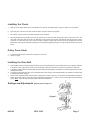
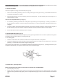
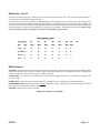
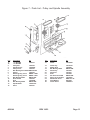
1
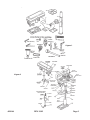
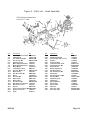
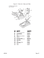
38144
16-Speed Drill Press
Assembly and Operating Instructions
®
3491 Mission Oaks Blvd., Camarillo, CA 93011
Visit our Web site at http//www.harborfreight.com
Copyright 1998 by Harbor Freight Tools®. All rights reserved. No portion of this
manual or any artwork contained herein may be reproduced in any shape or form
without the express written consent of Harbor Freight Tools.
For technical questions, please call 1-800-444-3353.
THANK YOU for choosing a Harbor Freights Tool product! For future reference, please complete the
owner’s record below:
Model: _________________ Serial No: __________________________ Purchase Date: ______________
SAVE THE RECEIPT, WARRANTY CARD AND THESE INSTRUCTIONS. It is important that you read the entire
manual to become familiar with the unit BEFORE you begin assembly.
Technical Specifications
SKU: 38144
Model: 13 inch Drill Press-16 Speed, Floor Model
Power Source: 120V, 60HZ, Single-Phase,
Speeds: Sixteen (16) speeds ranging from 220 to 3600 RPMs
Drill Chuck Capacity: 7/64” to 5/8”
Spindle Stroke: 3-1/8”
Swing: 13-1/2”
Column Diameter: 2-57/64”
Table Type: 11-1/2” square-dry table that rotates 360 degrees and tilts 0-45 degrees in one-degree increments.
Table T-Slot Dimensions: 1/2”
Overall Height: 62-7/8”
Unpacking
Unpack and check contents. Make sure you have all parts described in the Parts Lists and Figure 1 on page 3.
Remove all preservative lubricants from parts with a clean dry cloth.
Some of the parts are heavy and may require two people for lifting.
If any parts are missing or broken, please call Harbor Freight Tools at 1-800-444-3353. The shipping box should contain:
A.
B.
C.
D.
E.
Table Assembly
Arm
Instruction manual and warranty card
One Bag of Parts
Base
#38144
REV 10/03
F.
G.
Head Assembly
One (1) box of loose parts
J.
Column Assembly
REV 03/04
Page 2
Figure 1
Spindle
Belt is M24
Figure 2
#38144
Motor
Belt is M25
REV 10/03
Page 3
Work Area
TO AVOID RISK OF PERSONAL INJURY, EQUIPMENT DAMAGE, FIRE AND SHOCK, MAKE SURE YOUR WORK AREA IS:
Free of damp, wet or rainy conditions
Free of flammable gasses or liquids
Childproof - use padlocks, master switches and remove starter keys when not in use.
Well-lit
Clean and uncluttered
Well-ventilated
The Operator
COMMON SENSE AND CAUTION ARE FACTORS WHICH CANNOT BE BUILT INTO ANY PRODUCT. THESE FACTORS MUST BE SUPPLIED BY THE OPERATOR.
PLEASE REMEMBER:
Prevent body contact with grounded surfaces such as pipes or radiators.
Stay alert. Never operate equipment if you are tired.
Do not operate the product if under the influence of alcohol or drugs. Read warning labels on prescriptions to
determine if your judgment/reflexes might be impaired.
Do not wear loose clothing or jewelry as they can be caught in moving parts.
Non-skid footwear is recommended.
Wear restrictive hair covering to contain long hair.
Use eye and ear protection. Always wear:
ANSI-approved dust mask or respirator when working around metal, wood, and chemical dusts and mists.
A full face shield if you are producing metal or wood filings.
Ear protectors
Keep proper footing and balance at all times.
Do not reach over or across running machines.
Always check that adjusting keys and wrenches are removed from the tool or machine work surface before plugging it in.
#38144
Page 4
Before Operating
√
Know the machine.
potential hazards.
Learn its applications and limitations, as well as the specific
√
Check for damage.
If part of the machine
inspected to ensure that it can perform its
in doubt, the part should be replaced.
√
is
damaged, it should be carefully
intended function correctly. If
Be sure the switch is OFF before plugging in.
√ Before starting machine check to ensure that all chuck keys, spanners and wrenches
are removed from the machine.
√
Make sure guards are in place and working order.
√
Make sure tool has been cleaned and properly lubricated.
√ Check for damaged parts. Before using any tool, any part that appears damaged should
be carefully checked to determine
that it will operate properly and perform
its intended function.
√
Check for alignment and binding of all moving parts, broken parts or mounting
fixtures and any other condition that may
affect proper operation.
Any part
that is damaged should be properly repaired or replaced by a qualified technician.
√
Do not use the tool if any switch does not turn off and on properly.
Operation
√This drill press is designed for use with DRILL BITS and MORTISING
ATTACHMENTS only. The use of other cutting tools or
accessories could be hazardous.
√ Always use clamps, or a drill vise bolted to the table, to hold the work.
never be held in place by just your hand.
It should
√ Never force the tool or attachment to do the work of a larger industrial tool. It
is designed to do the job better and more safely
at the rate for which it
was intended.
√
Always unplug the cord by the plug.
√
Always turn off the machine before unplugging.
√
With normal use, the motor housing may get hot.
√
Make all adjustments to the machine with the power OFF.
√
Never stand on the machine.
over.
Never yank the cord out of the wall.
Serious injury could occur if the machine is tipped
√
Always use the correct drilling speeds for the drill size and the type of material
being drilled
√
Never leave the drill unattended while it is running.
√
When turning off the machine, never leave unit it has come to a complete stop.
√ Never hold material to be drilled with your bare hands. Damage to the machine may
also occur if the flung material strikes the column.
#38144
Page 5
Assembly (Please refer to Figure 2 and Parts Lists/Diagrams)
CAUTION! Consider the weight of the components and take necessary precautions when lifting components. Assistance
will be required when assembling.
Before adjustments are made, ensure that the machine is SWITCHED OFF AND UNPLUGGED. Also make sure all locking
handles and securing screws are FULLY TIGHTENED when adjustments are completed.
Before assembling, remove all traces of preservative from the components and wipe all parts thoroughly with a clean dry cloth.
Apply a thin coating of light machine oil to the table, column and base to prevent rust.
Column Assembly to Base
MOUNTING SURFACE: Ideally, the base should be firmly bolted to the floor or workbench prior to assembly of other components. The mounting surface must be flat, level and capable of supporting the drill press’weight combined with materials to be
drilled. Mount the drill at a sufficient height so you need not bend your back to operate.
1.
With the Base on a flat level surface, bolt on the Column Support (#4B) using the five 10 x 40mm hex head screws provided.
2.
Tighten firmly.
Table and Support Arm to Column
1.
2.
3.
4.
5.
6.
7.
8.
Remove the rack (#2B) from the column by slackening off the collar grub screw (#11B) and removing the collar (#19B). The
rack is stowed in this position for transit purposes.
Lubricate the worm gear (#18B) with light grease, and insert it shaft first fully into its housing in the arm until it is flush with
the helical gear (#17B). Hold it in this position. The worm gear shaft will extend through the housing ready for the crank to
be attached later.
Gently slide the arm assembly over the column and hold it steady while inserting the rack down through the worm gear
housing until it is flush with the helical gear, ensuring the long smooth end of the rack faces up. Place the bottom end of the
rack in the groove formed by the column support and the column.
Hold in this position while replacing the collar on the column. Ensure that the end of the rack is firmly engaged in the groove
formed between the collar and the column. However, there must be a working clearance between the rack and collar —
make sure the rack is not pinched. Firmly secure the collar with the grub screw.
Thread the Arm Locking Handle (#16B) in from the left, and tighten to secure the arm to the column.
Attach the table crank (#8B) to its spigot and tighten the securing screw.
Slacken off the arm locking handle and turn the crank, testing to ensure the arm will move the full length of the rack easily,
without binding, and will also rotate about the column evenly and without tight spots. Note: If too tight, nip up the arm
locking handle and slacken off the collar grub screw. Adjust to give a greater working clearance between the rack and
collar, tighten the grub screw and test again.
Insert the table into its housing on the arm and secure with the table clamp (#13B).
Head to Column
1.
It may be necessary to unscrew the Head Lock Set Screws (#21A) slightly to ensure they do not protrude internally, as this
will prevent the head from sliding fully into position.
2.
With assistance, raise the Head and place it on top of the Column, ensuring it slides home fully.
3.
Align the head with the base and firmly secure with the Set Screws (#21A) provided.
4.
Screw the three Feed Handles (#24A) and screw them firmly into the hub of the spindle feed shaft (#25A).
#38144
Page 6
Installing the Chuck
1.
With the Chuck Guard lifted clear of the spindle nose, slide the work table up the column to within 6” of the spindle.
2.
Open the jaws of the chuck to their maximum width, using the Chuck Key supplied.
3.
Put a piece of scrap wood on the table to protect the Chuck Nose.
4.
Ensuring all parts are thoroughly clean and dry and burr free, insert the arbor (#14) firmly into the end of the chuck. The
other end of the arbor, with the chuck now attached, is then inserted into the end of the spindle shaft (#13) turning, where
necessary, to ensure the tang on the end of the arbor is aligned correctly with the drive slot in the spindle shaft. Pull the
spindle down using the feed handles, pressing the chuck jaws hard against the piece of scrap wood until the chuck is forced
home.
Pulley Cover Knob
1.
2.
Locate the knob with pan head screw and attach to the cover.
Screw on tightly.
Installing the Drive Belt
1.
2.
3.
4.
Undo the Belt Tension Locking Knobs (one either side of the head #18A) and turn the Belt Tension Lever (#19A) clockwise
to bring the motor pulley (#11A) closer to the spindle pulley (#3) which will allow the belts to be slipped on with ease.
Lubricate the Idler Pulley Pivot shaft (#20) and Idler Pulley with light grease and install in its mounting between the motor
and Spindle Pulleys.
Consult the chart inside the pulley cover (and duplicated in this manual) and install the belts in the positions corresponding
to spindle/drill speed required.
Turn the belt counterclockwise so that tension is applied to the belts. Tension is correct when the belt deflects by approximately 1/2” at their centers of run when using reasonable thumb pressure. Lock the motor in this position using the locking
screw. Note: If the belt slips during operation, adjust the belt tension.
Settings and Adjustments
(Please refer to Figure 3)
Figure 3
#38144
REV 10/03
Page 7
Before adjustments are made, ensure that the machine is SWITCHED OFF AND UNPLUGGED. Also make sure all locking
handles and securing screws are FULLY TIGHTENED when adjustments are completed.
TO ADJUST THE TABLE
The table is capable of moving in four directions (see Figure 3).
1.
Raise or lower the table by slackening off the arm locking handle (A) and turning the crank (C) CLOCKWISE TO RAISE and
COUNTER CLOCKWISE TO LOWER.
2.
Swivel the table about the column by slackening off the arm locking handle. The table assembly, arm and rack (B) move in
unison around the column.
SETTING THE REQUIRED ANGLE (see Figure 3)
1.
Tilt the table by slackening the Bevel Table Locking Screw (E) and tilting to the required angle. A scale (F) is provided on
the arm measured in degrees, to assist in setting the required angle. For all normal operations, the table should be set to
0 degrees.
2.
To ensure the drill is entirely perpendicular to the table, insert a piece of straight round bar in the chuck, place a square on
the table and bring it up to the round bar. Adjust the table tilt if necessary so that the table is correctly aligned.
3.
Turn the table about its axis by slackening off the clamp (D).
TO SET DRILLING DEPTH (See Figure 4)
Located around the Spindle Feed Shaft is a Depth Stop Collar (A) with a graduated scale. The collar is capable of turning about
the shaft and can be locked in place by a Locking Screw (B).
To set a drilling depth:
1.
Lower the Chuck until the drill contacts the surface of the workpiece and hold it in that position.
2.
Loosen the Locking Screw and turn the collar so that the measurement for the depth of the hole required is in line with the
pointer (C). Lock the collar in this position using the locking screw.
The drill is now set to drill holes to your predetermined depth from that particular start point (i.e., providing the surface of your
workplace is flat and level, you may drill a series of holes, each to the same depth).
Figure 4
CHANGING DRILL (SPINDLE) SPEED
Before changing the speeds, make sure the machine is switched OFF and UNPLUGGED.
1.
Open the pulley cover (#23).
2.
Slacken off the Belt Tension Locking Knobs (on either side of the head #18A) and turn the Belt Tension Lever (#19A)
clockwise to bring the Motor Pulley (#11A) closer to the Spindle Pulley (#3) in order to remove all tension from the drive
belts.
#38144
Page 8
3.
Consult the chart inside the pulley cover (or Figure 5) and position the belts on the pulleys according to the spindle/drill
speed required
4.
When the belts have been correctly positioned, tighten them by turning the Belt Tension Lever counter clockwise until the
belt deflects by approximately 1/2’ at its center when using reasonable thumb pressure. Lock the lever in this position with
the two Locking Knobs.
Operation
1.
Insert the drill into the jaws of the chuck approximately 1”, ensuring that the jaws do not touch the flutes of the drill. Before
tightening the chuck, ensure that the drill is centered within the jaws. Tighten.
2.
Make sure the table height and position is set so that the drill travel range is sufficient for the material to be drilled.
3.
Make sure the work is securely clamped. That is, held in a drill vise, or bolted to the table. Never hold the material with your
bare hands while drilling. Severe personal injury may be caused if the material is flung out of the operator’s hand.
4.
IF THE MATERIAL IS IRREGULARLY SHAPED and cannot be laid flat on the table, it should be securely blocked and
clamped. Any tilting, twisting or shifting will result not only in a roughly drilled hole but also increases the chances of
damage to the drill.
5.
FOR FLAT WORK, lay the piece on a wooden base and clamp it down firmly against the table to prevent it from turning.
6.
FOR SMALL MATERIALS that cannot be clamped to the table, use a drill press vise. Make sure the vise is clamped or bolted
to the table.
7.
WHEN DRILLING COMPLETELY THROUGH WOOD, always position a piece of scrap wood between the material and the
table to prevent splintering on the underside of the material as the drill breaks through. The scrap piece of wood must make
contact with the left side of the column as shown in Figure 6. Also, set the depth of the drill so that the drill will not come in
contact with the table - or align the table so that the hole in its center is in line with the drill bit.
Figure 6
8.
Once the instructions above have been followed, lower the drill bit into place and switch the machine ON .
Note: A micro switch is provided inside the Pulley Cover that prevents the machine from operating unless the Pulley Cover is
firmly closed.
Cutting Speeds
Factors which determine the best speed to use in the drill press operation are:
1.
2.
3.
4.
Type of material to be drilled
Size of hole
Type of drill bit
Quality of the hole/cut desired.
Generally, the SMALLER THE DRILL BIT the GREATER THE REQUIRED RPM. In soft material, the speed should be higher than
for hard metals.
#38144
REV 10/03
Page 9
Drill Speed Table
Note: Spindle Belt M24, Motor Belt M25
The table below shows the belt arrangements for given drill speeds (a full chart
is also located on the inside of the pulley cover).
After Operation
1.
Remove all residue from the machine and thoroughly clean all surfaces.
2.
Make sure all components are dry and machined surfaces lightly oiled.
3.
Remove drill bits and store in a safe place.
4.
Child-proof the machine and work area. Make sure to use padlocks, master switches and remove starter keys.
Grounding/Voltage Warning
Common household current is 110-120 volts. As long as your tool is rated from 110-120V there will be no complications using
this tool with household receptacles. Plug the press into a 110-120V properly grounded outlet protected by a 15-amp, dual
element time delay or circuit breaker.
NEVER try to plug a 110-120V tool into a 220-240V circuit (or vice-versa) or serious complications and possible injury to the
operator may occur. The plugs have different shapes to prevent this.
This piece of equipment has a three-prong plug. The third (round) prong is the ground to protect the operator from electric shock.
Cutting off the ground will result in a safety hazard and void the warranty.
#38144
REV 10/03
Page 10
Extension Cords
Your tool has a three-prong plug, therefore you must use a three-prong extension cord. Only use rounded jacket extension
cords listed by the Underwriters Laboratories (UL).
The extension cord must have a minimum wire size depending on the amperage of the tool and the length of the extension cord.
This size is determined by its AWG (American Wire Gauge) rating. The smaller the gauge, the greater the cable’s capacity. The
amount of cords used does not matter: Total length determines the minimum AWG rating. Every cord must meet the AWG rating.
Use the chart below to determine what AWG rating is required for your situation. Cord length is rated in feet. Harbor Freight
Tools can supply UL listed and outdoor rated cords in multiple AWG ratings if needed.
Maintenance
CLEANING: Regularly clean the work surface with dry brush or clean cloth. Keep machined parts of the press lightly greased.
Always keep the motor and chuck clean. Prevent metal, wood, dust and debris from accumulating in this area. If jaws do not
operate smoothly, have the chuck serviced by a qualified technician.
LUBRICATION: For average use, lubricate twice a year with #20-30 weight household oil. Lubricate more frequently with
increased usage.
POWER CORD: Inspect the power cord periodically and, if damaged, have it repaired by an authorized technician.
REPLACEMENT PARTS: Replace belts at the first sign of slippage or fraying. When servicing, use only identical replacement
parts. Use of any other parts will void the warranty.
STORAGE: Always remove and store drill bits.
KEEP OUT OF REACH OF CHILDREN
#38144
Page 11
#38144
Page 12
Figure 7 - Parts List - Pulley and Spindle Assembly
1b
1a
Item
1a
1b
2
3
4
5
6
7
8
9
10
11
12
13
14
Description
No.
“V” Belt M24
1505010
“V” Belt M25
Pulley Nut
1302025
Spindle Pulley
1305009A
Pulley Insert
1302022
Ball Bearing17mm 60203 GB2778-89C
Spacer
1302023
Retaining Ring 17mm
GB894.1-86B
Retaining Ring 11mm
GB894.1-86A
Ball Bearing 60201
GB278-89A
Quill Gasket
1303003
Quill
1303002B
Ball Bearing 80202
GB278-89D
Spindle Shaft
13003001A
Arbor
1503007
#38144
Item
15
Description
Chuck
No.
1502009A
16
17
18
19
20
21
22
23
24
25
26
Chuck Key
Wedge Drift
Ball Bearing 60202
Idler Pulley
Idler Pivot
Knob
Pan Head Screw M5
Pulley Cover w/labels
Washer HD Screw
Foam Washer
Chuck Guard
1503010A
150300B
GB278-89B
1505006
1505007
1505008
GB818-85B
1305000C
GB9074.1-88
0805009
1508002A
REV 10/03
Page 13
Figure 8 - Parts List - Head Assembly
Part Numbers shown here
have an “A” suffix
Item
1A
2A
3A
4A
5A
6A
7A
8A
9A
10A
11A
12A
13A
14A
15A
16A
17A
18A
19A
20A
21A
22A
23A
Description
No.
Head w/pointer and trim 1302001A
Cable Clamp
15020114A
Pan Head Screw M5
GB818-85B
Hex. Screw M8
GB5781-86B
Adjusting Lever
1502006
Motor Support Bracket 1502002
Motor Support Bracket 1502003
Motor Mount
1502007A
Lockwasher 12mm
GB93-87
Nut Hex. M12x1.75
GB6170-86E
Motor Pulley
1505005
Skt. Screw Set M6
GB80-85A
Motor
1302020B
Hex. Nut M8
GB6170-86C
Washer M8
GB97.2-85
Motor Cable
1502016B
Hex. Screw M8
GB5782-86A
Belt Tension Lock Knob 1502005
Belt Tension Lever
1502004
Roll Pin
GB879-86
Head Lock Set Screw M8 GB80-85B
Depth Lock Screw
1504012
Knob
1304011
#38144
Item
24A
25A
26A
27A
28A
29A
30A
31A
33A
34A
35A
36A
37A
38A
39A
40A
41A
42A
43A
44A
45A
46A
Description
Feed Handle
Spindle Feed Shaft
Collar Depth Stop (w/scale)
Stop Pin
Connector Wire
Lockwasher Ext. 5mm
Pan Head Screw M5
No Volt Switch
Switch Plate Cover
Pan Head Screw
Pan Head Screw M5
Switch Box
Screw-Special Set M8
Hex. Nut M12
Quill Spring Cap
Quill Spring
Spring Retainer
Spring Seat
Power Cable
Cable Tie
Allen Key 4mm
Allen Key 3mm
No.
1304005
1304002
1304003
1304010
1302019
GB862.1-87
GB818-85B
1502010E
1302009A
GB845-85
GB818-85B
1302008B
1302021
GB6171-86E
1504008
1504009
1504007
1504006
1302015B
1502017
GB5356-86B
GB5356-86A
Page 14
Figure 9 - Parts List - Base and Table
Part Numbers shown here
have a “B” suffix
Item
1B
2B
3B
4B
5B
6B
7B
8B
10B
11B
12B
13B
14B
15B
16B
17B
18B
19B
#38144
Description
Column
Rack
Hex. Socket Screw Set M10
Column Support
Hex. Head Screw
Base
Table Support w/indicator
Crank
Gear Pin
Skt. Screw Set M6
Bevel Table Lock Screw M16
Table Clamp
Arm w/scale
Table
Arm Locking Handle
Helical Gear
Worm
Collar
No. CDP350F
1301003
1301010
G B80-85C
1301002
GB5781-86
1301001
1501004
1001009
1501007
GB80-85A
GB5781-86C
1501013
1301005
1601014
1501012
1501006
1501008
1501011
Page 15