1
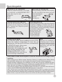
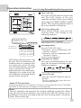
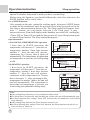
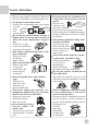
Haier Network Air Conditioner
Two by One Room Air Conditioner
AD422BMBAA
CONTENTS
Before Use
Operation Points************ 1
Name of Parts*************2-3
Safety Precautions**********4-5
Operation Instruction
Fan Operation***************
Auto, Cooling, Dehumidifying,
Heating operation************7
Timer On/Off Function*********8
Timer On-Off Function ********9
Sleep Function*************10
Usersí Attention************11
Maintenance
Maintenance*************12-13
Troubleshooting********** 14-16
Installation of Indoor Unit
Installation Instruction*******17-18
Installation Procedure *******19-29
No:
0010571812
Please read this manual carefully before using
Please keep this manual for future use
Characteristics of Products
Characteristics of Products
1.Prompt temperature adjustment.
2.Inner hidden type installation, space saving.
3.Large screen LCD display, easy and convenient operation.
4.Super quiet design.
5.Powerful circular air volume.
6.This air conditioner has POWER FAILURE RESUME FUNCTION. During
the operation of the unit, if there is a sudden power failure, when the power
resumes, the unit will resume the previous operation mode.
7.This unit has the function of far distance monitoring. Through the telephone
network, it can be effectively controlled in any other far-distance place.
(Only after equipped with the ìfar distance detectorî made by our company
can this function be fulfilled.)
Far distance monitoring
There is a pre-set far distance control communication interface on the control
panel of indoor unit. After installing the peripheral equipment according to the
manual attached with the Haier made far distance control detector, the
computer management or other place monitoring can be achieved to the air
conditioner.
Operation points
Operation of air conditioner
Anti-cold air blowing out
When the ambient humidity is too high,
in COOLING or DEHUMIDIFYING
mode, there may be water
dropped in
the air
outlet.
During Heating operation, after starting
the unit, the indoor fan motor will not
rotate immediately
Please wait
to prevent cold
air from
?
blowing out.*
3-minute protection function
Defrosting function
If start the unit immediately only after it
is turned off, the compressor will start
after 3 minutes have elapsed to protect
the compressor.
During Heating operation, when frost formed
on the heat exchanger of outdoor unit, the air
conditioner will defrost automatically for
several minutes. During defrosting, both the
fan of indoor and outdoor
unit do not run. After
finishing defrosting,
the air conditioner
will automatically
resume operation.
Change of fan speed
In COOLING mode, the air sending is set at AUTO,
when the indoor temperature is near the set
temperature, the fan speed will lower automatically.
In HEATING mode, when room
temperature reaches the set
temperature, the compressor will
stop running, and the fan will
change to LOW FAN or stop.
Hint
When the air conditioner is
in Heating mode, it absorbs
heat from outside and release
to indoors. So the outdoor
temperature may affect the
Heating effect.
In DEHUMIDIFYING mode, the fan
speed will change automatically.
Power failure resume function (please set and use this function according to actual
condition)
After setting power failure resume function, if there is a sudden power failure during
unit operation, when power on for again, the unit will resume the previous state.
Setting method: when the wire controller is in ON state (except for TIMER and FAN
mode), press the SLEEP button for 10 times in 5 seconds, after the buzzer sounds 4
times, the unit will change to POWER FAILURE RESUME function.
Cancellation method: press the SLEEP button 10 times in 5 seconds, after the buzzer
2 times, the POWER FAILURE RESUME function is cancelled.
Note: After the unit is set POWER FAILURE RESUME function, if there is a sudden power failure
in using, during this period of time if there is no need to use the unit for a long time, please cut off
power to prevent the air conditioner from automatically resuming to the previous setting if power
failure resumes, or press the ON/OFF button to turn off the unit after power failure resumes.
1
Name of Parts
3
1
2
* Air outlet
2
* Air inlet
* Ventilation hole
Name of Parts
Wire Controller
14 15 16 17 18
19
13
12
11
10
9
8
7
6
5
4
FAN
MODE
SWING
20
AUTO
TEMP
SET
CLOCK
SET
TIMER
SLEEP
21
22
23
24
25
26
27
28
22.Setting button
Used to confirm
the time of timer
3
ON/OFF
and clock
2
23.Sleep button
1
Used to set Sleep
13.Sleep state display
1.ON/OFF button
state
14.Network
control
display
Used to turn on/off unit
24.Time Adjusting
15.Working mode display
2.Temperature display
button
Working Auto
Cooling Dehumidifying Heating Fan
3.Clock display
mode
operation operation operation
operation operation
4.Timer ON/OFF display
Used to adjust the
Wire
controller
time of timer and
5.Humidity display
clock
6.Air filter cleaning display
16.Electric heating display
When there is too much dust
17.Operation mode button
25.Reset button
collected on the air inlet, the
Used
to
set
working
mode:
wire controller will show
When the wire
Auto, Cooling, Dehumidifying,
this display to remind the
controller appears
user to clean the air inlet.
Heating, Fan
abnormal condition,
After cleaning and installation,
18.Fan speed button
*
use a sharp-pointed
just press the air filter reset button.
Used to set fan speed: Low
article to press this
7.Super/Soft operation display
Fan, Med Fan, High Fan, Auto
button to make the
8.Fan speed display
19.Swing button
wire controller
Auto
Used to set Auto Swing or
resume normal
Fixed air sending direction
26.Air Filter Reset
Low Fan Med Fan High Fan Auto
20.Temperature Setting button
button
9.Auto Swing display
Used to set temperature,
After
cleaning the
10.Health state display
temperature range: 16*~30*
air inlet, press this
11.Fresh air state display
21.Clock button
button, the unit
12.Humidifying state display
can start to operate
Used to calibrate the time of
timer and clock
27.Timer button
Used to set the
Note:
mode of timer
1.This model does not have the following related
display and function * * 9 10 11 12 16 28
28.Lock state display
SUR
FILTER RESET RESET
Calibration of clock
When turning on the unit for the first time, the clock should be calibrated. The method
of calibration is:
1.Press ìClockî button, the Clock display ìAMî ìPMî will flash.
2.Press * or * to adjust time. For each press, the time will increase or*decrease 1
*minute. If depressing the button, the time will increase or decrease*rapidly.
3.After confirming the time, press ìSetî button, ìAMî or ìPMî will stop flashing,the
clock will begin to work.
3
Safety Precautions
Before starting the unit, please read the following ìSafety Precautionsî carefully
to guarantee the normal operation of the system.
The following lists two kinds of safety precautions ì Warningî and ì Noticeî.
For the items that the improper use may cause death or serious injury are listed
in ì Warningî volume. However, sometimes the items listed in ì Noticeî
volume may also cause serious accidents. So, these two volumes are the important
contents related to safety, they must be observed.
Do not do like this
Do follow the instruction
Do equip with grounding wire
After carefully reading this manual, please keep in hand for reference. If the
air conditioner is given to a new user, this manual should be attached with unit
to the new user.
Installation Safety Precautions
Warning
The system should be applied to places as The system should be installed by your
office, restaurant, residence
dealer or a professional installer.
and the like.
Application to inferior environment such Installation by yourself is not encouraged.
as workshop, it may cause equipment Because improper installation could cause water
malfunction and serious injury or death.
leakage, electric shock and fire accident.
Notice
A creepage breaker Drain pipe should be arranged Make sure the system is grounded.
must be installed at properly to provide a smooth
the installation place drainage.
NO
Grounding wire should
never be connected to gas pipe,
Unless the circuit If the pipe is
city water pipe, lightning conductor
breaker is installed, arranged improperly, furniture rod or the telephone line. If the
it may cause electric or the like may be damaged by grounding wire is not set properly, it
shock.
the leaked water.
may cause electric shock.
OFF
Operation safety precautions
Warning
Do not let the cold wind blow to human When any abnormal condition (scorching smell
body for a long time.
or others) is found, stop operation immediately
and turn off the power switch.
Then consult your dealer.
It may affect the physical condition or If continuing the operation without removing the
cause, it may cause trouble, electric shock or fire.
cause some health problems.
Notice
Do not handle switches with a wet hand. Do not use water to clean
the air conditioner.
It may cause electric shock.
4
It may cause electric shock.
Safety Precautions
Notice
The system should never be
used for any other purposes
than intended such as for
preservation of food, flora and
fauna, precision devices or
work of art.
Do not put or use any
spray near the air
conditioner, and do not
directly spray to the air
conditioner.
Do not put the fire
devices in the places,
which the air from the
air conditioner can
directly blow.
It may cause the fire
It may cause deterioration of Otherwise it may cause devices cannot burn
completely.
fire.
the articles.
Do not install the system where the air Only use the proper specified fuse.
outlet may directly reach the flora and
fauna.
It will not be good for their health.
If use metal wire or copper wire to
replace the fuse, it may cause trouble
and fire accident.
Do not use the power
switch to turn of or
off the air
conditioner.
When operating the system When cleaning, please
simultaneously with a combustion stop the unit and cut
apparatus, indoor air must be off the power first.
ventilated frequently.*
Do not perform
cleaning, when the
indoor fan motor is
It may cause fire or Insufficient ventilation may ca- rotating in high
use the danger of lack of oxygen. speed.
Creepage.
ON
OFF
Do not use such equipment as a water heater,
etc., around the indoor unit
or the wire controller.
Do not put the water containers,
such as vase, on the unit.
If the system is operated at the vicinity of such
equipment that generates steam, condensed
water may drip during cooling operation or it
may cause Creepage or short-circuit.
If the water enters
into the unit and damages
the electric insulation material,
it may cause electric shock.
Safety precautions when moving, reinstalling and repairing the air conditioner
Warning
Do not refit the air conditioner.
When repair is needed, please
contact your dealer.
Improper repair may
cause water leakage,
electric shock and fire accident.
When moving the air conditioner to another
installation place, please contact the dealer or
the professional installer.
Improper moving and reinstallation may cause
water leakage, electric shock and fire accident.
5
Operation instruction
Fan operation
1 Turn on the unit
MODE
2
FAN
TEMP
Press the ON/OFF button to turn on the
unit The LCD display of the wire controller
SWING
will show the previous working state (except
for Timer, Sleep, Swing mode), the operation
indicator light on the wire controller will light
up.
3
CLOCK
SET
TIMER
SLEEP
FILTER RESET
2 Choose of working mode
RESET
ON/OFF
1
4
Press MODE button, each press the
working mode will change as the
following sequence:
.
AUTO
COOLING
DEHU
HEATING
FAN
choose FAN operation
3 Adjusting FAN SPEED
Press the FAN SPEED button to change fan
speed:
LOW FAN
MED FAN
HIGH FAN
Choose the desired fan speed
4 Turn off the unit
Press the ON/OFF button to turn off the
unit.
The wire controller only shows the clock and
room temperature.
About FAN operation:
FAN operation refers the air conditioner does not perform COOLING and
HEATING operation, but FAN operation. In this mode, the air conditioner
cannot perform AUOT FAN operation, and does show the temperature value
on the wire controller.
6
Operation instruction
Auto/Cooling/Dehumidifying/Heating operation
1 Turn on the unit
2 MODE
FAN
TEMP
SET
Press the ON/OFF button to turn on the
unit The LCD display of the wire
controller will show the previous working
state (except for TIMER, SWING, SLEEP
mode). The operation indicator light on
the wire controller will light up.
SWING
4
3 CLOCK 3
SET
TIMER
SLEEP
FILTER RESET
RESET
2 Choose of working mode
5
Press MODE button, each press the
working mode will change as the
following sequence:
ON/OFF
1
When room temperature
is higher than set
temperature, unit in
COOLING operation.
AUTO COOLING DEHUMIDIFYING HEATING FAN
then choose AUTO, COOLING,
DEHUMIDIFYING, HEATING operation.
Ultra-low air flow
3
Set temperature + 2*
Set temperature
Set temperature
Press the TEMP. SET button
When room temperature
reaches set temperature
+ 2*, the unit will
operate in mild
dehumidifying operation.
In Heating operation, after start
the unit, the air conditioner will
sending warm air a moment later
to prevent the cold air blowing
out. In Dehumidifying, when the
room temperature drops 2*
higher than the set temperature,
regardless the set fan speed, the
air conditioner will intermittently
operate in low fan speed.
*Each press , the set temperature will
increase 1 degree.
*Each press, the set temperature will
decrease 1 degree.
Set the desired temperature.
4 Adjusting FAN SPEED
Press the FAN SPEED button, for each
press, the fan speed will change as the
following sequence:
AUTO
LOW FAN
MED FAN
HIGH FAN
AUTO
Choose the desired fan speed.
5 Turn off the unit
Press the ON/OFF button to turn off
the unit.
The wire controller only shows the clock
and room temperature.
About AUTO operation:
In AUTO operation, the air conditioner will operate and automatically choose COOLING,
HEATING or FAN operation according to room temperature.
Hints:
The wire controller can memorize the working condition of each time. When
start the unit for the second time, just need to press ON/OFF button, the air
conditioner will work according to the previous working mode. (except for
Timer, Sleep and Swing)
7
Operation instruction
MODE
FAN
SWING
TEMP
SET
CLOCK
SET
TIMER
SLEEP
FILTER RESET
RESET
Timer On/Off function
Before using TIMER function, calibrate the
clock first (referring to page 3). When you
wake up in the morning, before going back
to home after work or after going to bed, you
can let your air conditioner automatically turn
on or turn off.
1.Turn on the unit
After turning on the unit, set the desired
working mode.
The LCD of the wire controller will show working
mode. (except for Timer, Sleep, Swing)
ON/OFF
2.Set of TIMER mode
Press the TIMER button to change the
TIMER mode, each press the TIMER mode
will change as the following sequence:
ON
AM
TIMER ON
OFF
PM
TIMER OFF
ON
AM
OFF
Blank
PM
TIMER ON-OFF
Then choose the timer mode as you need
(TIMER ON or TIMER OFF.)
*
*
OFF
At this time the* ON * or
will flash.
3.Set time
Press the time adjusting button
* Each press, the set time increases 10 minutes. If depress the button, the time will
increase rapidly.
*Each press, the set time decreases 10 minutes. If depress the button, the time will
decrease rapidly.
This LCD will show the time set, the time can be adjusted within 24h.
(AM stands for morning, PM stands for afternoon).
4.Confirm the time
After calibration of the clock, press SET button to confirm time.
At this time, the* ON *or*
*will not flash.
OFF
The time displayed is: at x oíclock x minutes the unit will be turned on
(TIMER ON) or turned off (TIMER OFF).
Cancel TIMER
Press the TIMER button several times until the TIMER mode display
disappears.
Hints:.
After power failure, the clock should be calibrated again.
The wire controller has memory function, when you use this function for the
second time, if the time set is the same as the previous one, you just need to
choose the TIMER mode then press the SET button to confirm.
Operation instruction
Timer On-Off function
1.Turn on the unit
MODE
FAN
After turning on the unit, set the desired
working mode.
The LCD of the wire controller will show
working mode. (except for Timer, Sleep,
Swing)
SWING
TEMP
SET
CLOCK
SET
TIMER
SLEEP
6
FILTER RESET5
RESET
2.Set of TIMER mode
Press the TIMER button to change the
TIMER mode, each press the TIMER mode
will change as the following sequence:
ON/OFF
ON
AM
TIMER ON
3.Set time
Press the time adjusting button
OFF
ON
OFF
PM
AM
TIMER OFF
TIMER ON-OFF
Blank
PM
Then choose the TIMER ON-OFF mode.
At this time the" ON "will flash.
* Each press, the set time increases 10 minutes. If depress the button, the
time will increase rapidly.
*Each press, the set time decreases 10 minutes. If depress the button, the
time will decrease rapidly.
This LCD will show the time set, the time can be adjusted within 24h.
(AM stands for morning, PM stands for afternoon).
4.Confirm the time
After adjusting time, press SET button to confirm time.
OFF
At this time, the* ON *will not flash ,*
*begins to flash.
The time displayed is: at x oíclock x minutes the unit will be turned on.
5.Set the TIMER OFF time
Press the TIME button, the adjustment method is the same as the one of
setting TIMER ON time.
6.Confirm the time of TIMER OFF
After adjusting time, press SET button to confirm time.
At this time, the" OFF "will not flash.
The time displayed is: at x oíclock x minutes the unit will be turned off.
Cancel TIMER
Press the TIMER button several times until the TIMER mode display disappears.
According to the sequence of TIMER ON & TIMER OFF setting, you can
realize turning on unit first, then turning off unit.
9
Operation instruction
Sleep operation
Before going to bed, you can press the SLEEP button, the air conditioner will
operate in comfort sleep mode to make you have a sound sleep.
Before using this function, you should calibrate the clock first, otherwise, the
SLEEP function will be out of order.
Use of SLEEP function
After turning on the unit, setting the working mode, then press SLEEP button
to make the air conditioner have the previous Sleep time (powered on for the
first time or after performing Sleep is 1h). The Sleep symbol will appear. Press
time */* button, you can choose between 1~8h. Each press, it may
increase/decrease 1h and will display in the humidity area with ìxhî, and display
ìTimer Offî in Timer Off area and the time to turn off; press Sleep button again
to cancel Sleep function. The Sleep symbol disappears.
Operation modes
1.In COOLING, DEHUMIDIFYING operation
1 hour later in SLEEP operation, the
temperature will increase 1* from the set
temperature, another 1 hour later increase
another 1*, then the unit will operate
continuous for 6 hours, then it turns off
automatically. The temperature is higher than
set temperature to prevent you from getting
a cold.
2.In HEATING operation
1 hour later in SLEEP operation, the
temperature will decrease 2* from the set
temperature, another 1 hour later increase
another 2*, then the unit will operate
continuous at this temperature for 3 hours,
then it increases 1*, after operating at this
temperature for another 3 hours, the unit will
turn off automatically. The temperature is
lower than set temperature to prevent you
from feeling uncomfortable during sleep.
SLEEP operation stops
SLEEP operation starts
about 6 hours
1 hour
1 hour
increase 1*
increase 1*
Set temperature
turn off
in COOLING* DEHUMIDIFYING operation
Set temperature
turn off
1 hour decrease 2*
1 hour
decrease 2*
about 3 hours
3 hours increase 1*
SLEEP operation starts SLEEP operation stops
in HEATING operation
MODE
FAN
SWING
TEMP
SET
CLOCK
SET
TIMER
SLEEP
FILTER RESET
RESET
ON/OFF
Note:
lAfter setting Sleep function, it is not permitted to adjust clock.
lThe Sleep time is less than 8h, after reaching the set time, the unit will automatically stop.
lSet Sleep function after setting ìTimer Offî function, the air conditioner will perform
Sleep function.
lAfter setting Sleep function, the Timer function cannot be set.
lSet Sleep function after setting ìTimer Onî function, the Sleep function can only be set
in the set time of Timer On.
10
Usersí Attention
Do not press tightly with the LCD part of
the wire controller to avoid damage of it.
Set proper room temperature
Not too low or high and make every people in the
Heating is
room
Cooling is
18~23*
26~28*
feel
comfortable.
Do not let the cold air blows directly to
human body for a long time and do not
make the room temperature drop too
low.
Otherwise, it may
cause uncomfortable
or bad to your health.
The airflow cannot directly blow to the
pets and plants.
Otherwise, pets
and plants
may be hurt.
The room should often ventilate.
After a long-time
of using air
conditioner, the
room must be
ventilated.
Do not keep the doors and windows
open
Otherwise, it
may lower the
efficiency of
the air conditioner.
Television, radio and acoustics, etc.
equipment should keep over 1m from
indoor unit and wire controller.
Otherwise, they may
disturb the image
and cause noise.
Do not put any drying
devices under the
indoor unit.
The heat may cause the
deformation of indoor
unit.
If do not use the air conditioner for
a long time, it is necessary to cut off
power.
Cut off
If do not cut
power suplay
off power, the
unit may consume
power. In order to protect the unit,
before using the air conditioner again,
turning on the power at least 12 hours
in advance.
The windows should be hung with
curtains or blinds.
Do not let the sun
shine directly shine
in the room; do not
let the outdoor air
enter room.
The articles must keep dry cannot
be put under the indoor unit.
When the humidity
is over 80% or
the drainage
outlet is blocked,
the indoor unit may drop water.
Do not put articles around the air
inlet and outlet.
This kind of obstacle can lower the
efficiency of the air conditioner or cause
unit trouble.
The air conditioner can only be used
in air conditioning. It can not be
used in other purpose.
Do not use the air conditioner in some
specific purpose, such as storage or
protect food, animals, plants, precise
instrument and
artwork,
otherwise,
the quality
of them may
be declined.
11
Maintenance
Notice
The repair can only be performed
by the professional workers.
Before touch the wire connection
device, cut off the power first.
Notice
Do not use water to clean the air
conditioner.
Otherwise, it
may cause
electric
shock
Only after turning off the unit and
cutting off the power can the
cleaning of the unit be performed.
Otherwise, it may cause electric shock
or injury.
Donít in
operation
Use stable stand support.
Please pay high attention when
cleaning the unit
Clean the air filter
Clean
Notice
Do not use the hot water over 50* to clean to avoid discoloration
or deformation.
Do not dry the unit on fire, the filter may be burnt.
Use cleaner or water to clean to remove dust.
*A*Use
cleaner to remove dust.
* B *When
the dust is too much, use
soft brush and neutral detergent.
( C )
12
Throw the water off, then put it
in the shadow for airing.
Maintenance
Maintenance before and after the using season.
Before using season
1.Check the following items:
If the air inlet and outlet of indoor and outdoor unit are blocked.
If the earth wire is proper.
If the wire connection is proper.
If there is abnormal phenomenon, please ask the after-sale service staffs
for help.
2.Cleaning the air filter or air inlet and casing
After cleaning the air filter, it must be reinstalled.
3.Turn on the power
After turning on the power, words appear on the LCD screen of the wire
controller.
After using season
1.In a sunny day, perform half-a-day Fan operation to make the inner
of the unit dry.
2.Cut off the power
If do not cut off power, the unit will consume power. Power cutoff can
save power.
3.Cleaning the air filter or air inlet and casing
After cleaning the air filter, it must be reinstalled.
For the details of cleaning, please refer to Maintenance.
13
Troubleshooting
The following phenomena are not troubles
a,
H
Hu
Hear the sound
of water flow
ua
Symptom
Cause
When the air conditioner is started; during operation
the compressor starts or stops; or when the unit is
stopped; sometimes it gives the sound of ìHua,
Huaî or ìGudu, Guduî. This is the sound of the
refrigerant circulation, not trouble.
Gives ìPi, Paî sound
It is caused by the hot expansion and cold shrink of
the plastic part.
Having peculiar smell
Sometimes the air sent from the indoor has peculiar smell,
the smell is what the cigarette smoke naturally has or caused
by the inner paint of the unit.
During operation,
the indoor
unit
produces mist.
During COOLING or DEHUMIDIFYING, you may see
the unit produces whiffs of light mist. It is caused by the
sudden cold indoor air blown out from the unit producing
condensation mist.
During COOLING
operation, the mode
changes from AUTO to
FAN.
To prevent the frost from forming on the indoor unit heat
exchanger, sometimes the unit will automatically change
to FAN mode, but sooner it will resume to COOLING mode.
After stopping the
unit, it can not start
immediately.
Even the operation button is set on ON, within 3 minutes
after the unit stops, Cooling, Dehumidifying or Heating
mode can not start. It is because the self-protection of the
system.
Wait three
(In this 3 minutes,
minutes
the air conditioner is in Fan mode)
The air conditioner
does not start?
During
DEHUMIDIFYING, there
is no air blown out or the
FAN SPEED can not be
changed.
During operation, the
operation mode changes to
Auto.
14
In DEHUMIDIFYING operation, when the room
temperature is too low, the fan motor will automatically
and repeatedly drop the fan speed
Whether choosing Auto mode?
In Auto mode, according to room temperature, the operation
mode will automatically change Cooling to Heating, vice
versa.
When Troubles Occur
Before asking the commissioned repair center for help, please check the air conditioner
according to the following items.
The air conditioner can not start
Is the power
switch
connected?
ON
OFF
If the city electric If the wire controller If the earth
power supply is is directly shined by creepage breaker
normal?
sunshine or affected works?
with damp.
Please cut off
The power
power
switch is
immediately and
not at ON
contact with
position.
suppler.
Bad cooling effect
Did you adjust the If the air filter Are doors or
If the air inlet or outlet is
controller as what is too dirty?
windows closed? blocked by obstacles?
is specified?
Bad heating effect
If the air out louver is in horizontal? The air conditioner does not blow air in
(Heating mode)
Heating operation, if it is in anti-cold air
state? Referring to page7.
If the air out louver is horizontal,
the warm air can not blow on the
floor.
If after the above checking and treatment, the air conditioner still can not
work normally, or find the following phenomena, please stop the operation
of the unit and contact the commissioned repair center.
The fuse or breaker often opens circuit.
During Cooling or Dehumidifying, there is water leakage.
Abnormal operation or abnormal sound is heard.
The operation indicator light on the wire controller flashes and trouble code
(E0, E1, ..., E9) appears on the screen to indicate the trouble of the air
conditioner.
15
When Troubles Occur
When the following phenomena appear, please contact the commissioned repair center.
Warning
If finding any abnormal phenomena (such as adust smell), cut off power first,
then ask the after-sales service workers for help.
If still using the air conditioner in this condition, the air conditioner may be
damaged and causes electric shock or fire accident.
After taking the following measure,
Symptom
then contact the commissioned repair
center
The safety equipment, such as fuse, bre- Cut off power.
aker and creepage breaker, has been open
circuit for many times; or the operation
switch cannot work normally.
Cut off power and inform the commissioned repair center.
The air conditioner leaks water.
Trouble code display
Phenomenon of
outdoor unit trouble
The flashing time of indicator light Indoor control
on outdoor control panel
panel indication
The trouble of outdoor ambient
temperature sensor
The trouble of outdoor coil
temperature sensor
The trouble of outdoor discharging
air temperature sensor
The outdoor discharging air
temperature is too high
Over electric current protection
CT wire breaks
The communication trouble
between indoor and outdoor unit
Pressure protection
Phenomenon of indoor
unit trouble
Trouble indication on remote
control type indoor unit
The trouble of indoor ambient
temperature sensor
The trouble of indoor coil
temperature sensor
The trouble of outdoor ambient
temperature sensor
The trouble of outdoor coil
temperature sensor
The trouble of electric current
overload
The trouble of
overloadPressure protection
1 (A, B systems indicate together)
E3
2 (A and B system indicate individually)
E4
3 (A and B system indicate individually)
E4
4 (A and B system indicate individually)
E4
5 (A and B system indicate individually)
6 (A and B system indicate individually)
E5
E5
8 (A and B system indicate individually)
E8
9 (A and B system indicate individually)
E6
Trouble code on wire
control type indoor unit
The compressor indicator light flashes 1
E1
time in 0.2S/time frequency
The compressor indicator light flashes 2
E2
time in 0.2S/time frequency
The compressor indicator light flashes 3
E3
time in 0.2S/time frequency
The compressor indicator light flashes 4
E4
time in 0.2S/time frequency
The compressor indicator light flashes 5
E5
time in 0.2S/time frequency
The compressor indicator light flashes 6
E6
time in 0.2S/time frequency
The compressor indicator light flashes 7
E7
time in 0.2S/time frequency
The compressor indicator light flashes 8
The communication trouble
E8
time in 0.2S/time frequency
between panel and indoor panel
The communication trouble betw- The compressor indicator light flashes 9
E9
een indoor panel and outdoor panel time in 0.2S/time frequency
The compressor indicator light flashes 10
E0
The trouble of water pump
time in 0.2S/time frequency
16
Installation instruction
Before installing, do read this ìSafety precautionsî carefully to guarantee the proper installation.
The below attentive matters are divided into ì Warningî and ì Noteî two parts. When the wrong
installation occur, it is very possible death and severe injury and other serious accidents will happen. For
those items are listed in ì Warningî part. But even the items listed in ì Noteî part can also cause serious
accidents. Above all, both the two parts are very important contents related to safety, so they must be obeyed.
After finishing the installation work, do test run to verify everything is normal. After that please explain the
using and maintenance methods to the user. Additionally, give this installation manual and operation manual
to the user and ask them to keep it properly.
Warning
The commissioned repair center shall do the installation work. If you do the installation work by yourself,
the improper installation will cause water leakage, electric shock fire and other accidents.
The installation work shall be in line with what the installation manual specified. If installation is not
proper, water leakage, electric shock, fire and other accidents will occur.
Install the air conditioner to a place where can definitely stand its weight. The air conditioner can not be
installed on a nonmetal bracket (such as theft guard net). Places not firm enough will cause drop down of
unit resulting in body hurt.
The installation work shall be preventive to typhoon and earthquake. If the installation work is not met
with the requirements, overturn of the unit will occur resulting in accidents.
Using the specified cable to do wiring work and connecting firmly and properly. Fix the connecting part
of the terminals to prevent it from the external force. Improper connection and fixing will cause heating
and fire etc. accidents.
Wiring shall be kept in correct shape avoiding extrusion. After installation, the electric box cover and the
external panel shall not nip the wire. Improper installation will cause heating and fire etc. accidents.
When setting or moving the air conditioner do not let the air and things alike get into the refrigeration
system except the specified refrigerant (R22). If air and other things enter, abnormal high pressure will
occur, which easily cause break and body injuries etc. accidents.
When installing, do use the accessories or specified parts. If not using the parts specified by our company,
water leakage, electric shock, fire and refrigerant leakage will occur.
Do not lead the drain hose to drain where the sulfur gas may be involved. Otherwise, the poisonous gas
will enter into the indoor.
During installation, if refrigerant leakage occurs, do the ventilation work immediately. As soon as the
refrigerant gas meets fire, poisonous gas will be produce.
After installation, confirm there is no leakage of refrigerant. If the refrigerant gas enters into room and
meet the air blowing heater, heater or stove etc. fire source, the poisonous gas may be produced.
Do not install the unit in a place where the combustible gas may be leaked. In any case the combustible gas
leaks and accumulated around the unit, fire accident will occur.
The drain hose should be correctly installed according to the installation manual to ensure smooth drainage,
and take proper heat preservation measure to prevent from dew. Improper pipe installation may cause water
leakage result in wet the indoor articles.
Do heat insulation work to the refrigerant gas pipes and liquid pipes to reach the purpose of heat preservation.
If the heat insulation measure is not sufficient, water generated by condensing dew will drip leading to wet
the floor and indoor articles.
Note
Do grounding work. Do not connect the grounding wire to gas pipe, tap, lighting rod or telephone line.
Improper grounding will cause electric shock.
In some places the creepage breaker shall be installed. If do not install the breaker, electric shock may occur.
After electric installation, power on them to do electric leakage test.
17
Installation instruction
Notice
This manual can not include all kinds of conditions, if you have new
requirements and questions, please contact with local Haier Sales Center.
Warning
Before installing the unit, please read this manual carefully. Improper
installation may cause accidents and make unit damage or death.
Installation tools
1. Screwdriver
2. Steel saw
3. 60, 70mm diameter drill
4. Spanner (diameter 17,27mm)
5. Spanner (14, 17, 19, 27mm)
6. Pipe cutter
7. Pipe flarer
8. Knife
9. Pincers
10. Leakage detector/soap water
11. Tape measure
12. Scraper
13. Refrigerant oil
Accessories attached with the unit
The following is the manual mentioned standard accessories, please check them by
yourself. As the following figure shown
No.
1
3
2
Wire controller
Shape & (signal wire)
name
**
AUTO
**
4
Signal Refrigerant Little wire
clamp
wire
oil
5
6
Big wire
clamp
Thermal
insulation
pipe
2
2
**
**
**
**
**
**
***
**
**
**
****
**
E D O M N AG NF I W S
**/**
O
T
U
A
P M E HT T L A E H
K C O L C
M
T
E
S
O
O
R
R E M I T
T E S E R
Amount
1
E
S
6
7
8
9
10
11
Shape &
name
Plastic clamp
Seal cushion
Gasket
Cement
steel nail
Screw
Amount
6
8
12
3
No.
18
1
1
T
P E E L S
H . XR EU TA L I F
4
Installation procedure
Install indoor unit
1. Before installation [Before finishing installation, do not throw the attached
parts installation needs]
Confirm the way to move the unit to the installation place.
Before moving the unit to the installation place, do not remove their packages.
When have to remove the package, use a soft material or protection board with
rope to lift the unit assembly to avoid unit damage or bumping a scrape.
2. Choose installation place
(1)The chosen installation place should meet the following requirements and
get the userís consent.
Place ensures ideal airflow distribution.
The passage of airflow has no obstacles.
The condensate water can be drained smoothly.
Place can stand the weight of indoor unit.
Place ensures enough space for maintenance.
The pipe length between indoor and outdoor unit is in the permitted limit
(referring to outdoor unit installation part).
The indoor unit, outdoor unit, electric wire and connection wire is at least
1m away from television and radio. This is to avoid the image disturbance
and noise caused by the above-mentioned home appliance. (Even if 1m
away, if the electromagnetic wave is too strong, it can also cause noise.)
(2)The height of ceiling
The indoor unit can install on the ceiling, which height is no more than 2.7m.
(3)Install and use the hoisting screw. Check if the installation place can bear the
weight of unit assembly. If not certain, strengthen it before install the unit.
600
620
100
1720
Ceiling opening
Obstacle
Space installation needed (unit: mm)
19
Installation procedure
Install indoor unit
opening*
*Dimension of ceiling
620
(The position to hang
the screw)
545
3.Preparation before installation
(1) The position relation among ceiling opening and hoisting screws
(unit: mm)
Ceiling opening
1406
*The position to hang the screw*
1720
*Dimension of ceiling opening*
(2) If necessary, cut a opening on the ceiling for installation and checking.
(in original ceiling circumstance)
For the dimension of the ceiling opening, please refer to the above
Figure.
Before installation, finish the preparation work of all the pipes (refrigerant
pipe, drain hose) and wires (connection wire of wire controller and of
indoor and outdoor unit) first to make it easy to connect them to indoor
unit as soon as installation begins.
Cut a opening in the ceiling, it is necessary to strengthen the ceiling to
keep the ceiling level and prevent the vibration of the ceiling. For details,
please consult to the builder.
(3) Install the hoisting screw
(Use M10 screw bolt)
In order to bear the weight of the unit, for existed ceiling, using foundation
screw bolt, for new ceiling, using burying embedded screw bolt, burying screw
bolt or spot supplied other parts.
Before going on installation, adjust the gaps with ceiling.
In hole spud
In hole plug
Plug
Cement
Hoisting screw M10
20
Installation procedure
Install indoor unit
4. Installation of indoor unit
Fix the indoor unit on the hoisting screw.
If necessary, suspend the unit on the crossbeam. Do not use hoisting
screw, directly use screw bolt.
Hoisting screw
M10 screw nut
M10 washer
Main unit
M10 spring washer
Note:
If the dimension of main parts does not meet the opening of the ceiling,
adjust the slot of suspending bracket.
Adjust to level
(a) Use gradienter or other methods to perform level adjustment.
Perform level adjustment to make the relationship between the bottom
surface of the equipment and the horizontal surface as the shown below.
One side of pipe
Charging water
Horizontal
0~5 mm
(0~0.2")
PVC pipe
Make one side of the pipe a little bit lower
(b) Unless adjust to horizontal, otherwise the floating switch may have trouble or misplay.
Choose the air sending of the fan motor
(When use high performance air filter)
The fan motor is equipped with red and white terminals, when in
factory, the air sending has already been set at the standard choose.
When using the high performance air filter, etc. optional parts leading
to the static pressure rise, please according to the following figure shown
to change the connection of the connector installed on the side of control
box.
Red
Blue
Yellow
Red
Black
White
Blue
Red
One side of
Fan motor
Yellow
White
Connector,White
Red
Red
Blue
High fan speed air sending
One side of the
control box
Yellow
White
One side of
Fan motor
Blue
White
White
Connector,White
One side of the
control box
Standard air sending (when deliver the air conditioner)
21
Installation procedure
Install indoor unit
5.Drain hose
(a)The
drain hose should always have a slant degree (1/50~1/100) to avoid
the protruding part or causing water flow bend.*
Good pipe system
Improper pipe system
Suspending screw bolt 1.5m*2m
Avoid protruding part
Air outlet
Do not have bend
Do not put pipe under water
Insulation
1/100 or more slant degree
(b) When connecting the drain hose with equipment, be sure not to use too
much force to the pipe on one side of the equipment.At the same time,
the fixation of pipe should be close to equipment as possible as it can.
(c) For the drain hose, it can be the local bought stiff PVC pipe for normal
purpose. When connecting, insert the end of PVC pipe into the drain
hole, then use drain hose and wire fastener to fix them tight. The bond
can not be used to connect drain hole and drain hose.
Drain hole
Drain hole
Drain hose
Seal cushion (used for partition) (accessory)
Connector (local bought)
Main unit
**PVC*******
Drain hose
Bonded Seal cushion (used for partition) (accessory)
Wire fastener (accessory)
Seal cushion (used for partition) (accessory)
22
Installation procedure
Install indoor unit
(d) When the equipped drain hose
used to many units, the position of public pipe should be
100mm lower than the drain
hole of any unit. As the figure
shown. For this purpose, the
thicker pipe should be used.
Guarantee the most possible
high fall (about 100mm)
Indoor unit
Indoor unit
1/100 slant degree or more
(e) The stiff PVC pipe put indoor side should be heat insulated.
(f ) The lifting height of the drain hose should be at the position over ceiling
within 500mm. When there is obstacle on the ceiling , use bracket and
things alike to lift the drain hose to avoid the obstacle. During this work,
if the extending height is higher than 500mm, the return flow of drainage
may become too much leading to the drainage groove overflow. So, the
height of the drain hose should be kept within the tolerance range given
in the follow figure.
Top right side
Drain hose Connector
500mm
The max on-site
discharging
dimension
290~325mm
Connector
(locally bought)
(g) Avoid putting the outlet of drain hose in the places with irritant gas
generated. Do not insert the drain hose directly into drainage, where
the gas with sulfur may be generated.
Test of drainage system
(a) After finishing electric engineering, perform drainage system test.
(b) During test, confirm if the water properly passes through the pipe
and there is no water leakage in the joint.
(c) In a new house, perform test before installing the ceiling.
(d) Even if installing the air conditioner in a heating operation needed
season, the test also must be performed.*
Procedure
(a) Dismantle the side panel, slowly charge 1000cc water into the drain
pan to confirm the smooth drainage and without water leakage.
(b) In Cooling operation, check the drainage system.
23
Installation procedure
Install indoor unit
Insert into the water supplying pipe 20mm~30mm
(insert the drain hose toward bottom)
Pour water into the
protruding connector
Install the drain hose clamp
Drain hose
Main unit
Remove the rubber
stopper, after
finishing installation,
it must be reinstalled
Check the condition of drainage
through the transparent hose base
Before finishing the wiring work, install a protruding connector on the drain hose to provide
a water in hole. Then, if there is water leaks from the pipe system, perform check. Finally,
the water flow through the drain hose should normally pass.
6. Installation of air suction and discharging duct
Please consult the after-sales service
Main unit of air conditioner
worker of Haier Air Conditioner
for the choosing and installation
of suction inlet, suction duct, diInsulator
The surface
scharging outlet and discharging
of ceiling
Special air in nozzle
duct. Calculating the design dra(locally bought)
Checking hole
attached with air filter
wing and outer static pressure,
Air discharging
Air in pipe
and choose the discharging duct
pipe (locally bought) (locally bought)
with proper length and shape.
Special air discharging
nozzle (locally bought)
The length difference among
Correct
Incorrect
Incorrect
every duct is limited below 2:1.
Reduce the length of duct as possible as can.
Reduce the amount of bend as possible as can.
Use heat insulation material to bind and seal the part connecting main unit and
the flare part of air discharging duct. Perform duct installation work, before the
fitment of ceiling.
7. Connection of air suction and discharging duct
(a)Absorb of fresh air (single air supplying) (b)Air discharging
Side air absorbing
Use side air discharging nozzle
(do use together with air absorbing)
Connection pipe side
Connection pipe side
Use side air absorbing nozzle or
absorb from the air in pipe
Absorb from the air in pipe
Air discharging nozzle
Do not use this nozzle for air in
Absorb from the air in pipe
(c) Perform thermal insulation to the duct to prevent from frosting
24
Installation procedure
Install indoor unit
8.The attentive matters in installation of air suction and discharging duct
Recommend to use anti-frost and sound-absorbing duct. (locally bought)
The duct installation work should be finished before the fitment of ceiling.
The duct must be heat insulated.
The specific air-discharging outlet should be installed at the place where the
airflow can be reasonably distributed.
The surface should leave a checking hole for checking and maintenance.
9.The examples of improper installation
Special air discharging outlet
Use screw bolt to fix
Do not use air in duct and take the
ceiling inner side instead. The result is because of the irregular outer
Duct
air mass, strong wind and sunshine,
the humidity is increased.
Air
There may be water drop on the
Air
outside of duct. For cement and
other new constructions, even if
not taking ceiling inner side as duct, the humidity will also be so high.
At this time, use glass fiber to perform heat preservation to the whole.
(use iron net to bind the glass fiber)
Maybe exceeding the unit operation limit (for example: when indoor dry
bulb temperature is 35*, wet bulb temperature 24*), it may lead to overload of compressor.
Affected by the capacity of air discharging fan, the strong wind in the outer
duct and wind direction, when unit air sending volume exceeds the limit, the
discharged water of heat exchanger will overflow, leading to water leakage.
Air discharging fan
Improper example
25
Installation procedure
Install wire controller
1.Remove the upper cover of wire controller
The PC board is installed on the back cover of
wire controller. When remove the upper cover,
pay attention not to damage PC board.
Upper cover of
wire controller
Switch
Back cover
of wire
controller
Screw hole
2.Install wire controller
Drill 2 wall holes according to the position of the 2 screw holes on the back
cover of wire controller, then hit wood in the wall holes. Put the 2 screw holes on the back cover of wire controller properly to its corresponding wood,
then use wood screws to fix the back cover on the wall.
Note:
Install the back cover of wire controller on the even wall as possible as can.
When tightening the wood screw, do not use to tight force, otherwise the wire
controller may be damaged.
Switch
Mark
1
2
3
4
OFF
2 grades fan speed
No rise and drop
Not Swing
The collection temperature
of panel
ON
3 grades fan speed
Have rise and drop
Swing
The collection temperature
of main panel
Under this series, the switch is set as:1.ON 2. OFF 3. OFF 4.OFF
3.Indoor unit wire connection
Connect the terminals (A, B, C, D,) on the wire controller to the terminals on
the indoor PC panel (A, B, C, D,) respectively.
AB CD
Arrange wire
from this part
Back cover wire
controller
Note:When connecting wire, please keep a
certain distance between signal wire
and electric wire. (over 10mm)
Dimension of signal wire:
Type of wire Shield wire (4 cords)
Dimension
0.33mm2
*The connection between indoor unit
Upper cover of
and wire controller and indoor unit
wire controller
and outdoor unit should use shield
wire. And the two ends of the shield
Note:
Confirm the connection part of terminals wire should be grounded, otherwise,
the disturbance will cause unit abnis firm and will not touch shield wire.
ormal operation.
4. Cover the wire controller upper cover
Pay attention not to press the connection wire.
Shield wire
26
Note: (1) The power switch and the signal
wire are self-provided.
(2) Do not touch PC board by hand.
Grounded
Grounded
Installation procedure
Connection of pipe
1. Connection of pipe
Connection method
For the specific max length and the max fall of connection pipe, please refer
to the manual of outdoor unit.
In order to guarantee the efficiency, the pipe should be as short as possible.
Daub the refrigerant oil on the joint and the flared nut.
When bending the pipes, give the roundness as large as possible, to avoid
crashing the pipes.
To connect the pipe, fit the center and use hand to screw the nut, then use spanner to tighten the nut, as shown in figure.
Joint
Nut
Pay attention not to let alien matters,
such as sand, vapor get into the pipe.
The connection of indoor unit pipe
Spanner
must be performed by using two
spanners.
Spanner
2. Dimension of connection pipe
Pipe diameter
Fasten torque
Liquid pipe 9.52mm 32.7~39.9 N.m
Gas pipe 19.05mm 97.2~118.6 N.m
If do not fit the center and screw the nut
hard, the screw thread may be damaged,
which will cause refrigerant leakage.
3. The additional charging amount of refrigerant
The additional charging of refrigerant (R407C) should be complied with the
installation manual of outdoor unit. It must use measurer to quantificationally
charge. The additional charging amount must be complied with the specified
amount.
Requirements: Both excessive charging and less charging of refrigerant will cause the
compressor trouble. It must be complied with the specified amount.
4.Vacuumizing
Use vacuum pump to perform vacuumizing through the stop valve of outdoor
unit.
It is strictly prohibited to use the refrigerant sealed in the outdoor unit to
perform air discharging.
5.Leakage detection
Use leakage detector or soap water to check if the connected part of the
connection pipe and the valve cap leak.
6.Thermal insulation treatment
The thermal insulation of connection pipe should be performed at both gas
side and liquid side. In COOLING, both liquid side and gas side are in low
temperature, in order to prevent dew from forming, thermal insulation should
be done.
The thermal insulation material at the gas side must use the material with the
heat resistant temperature over 120*.
The connected part of indoor unit connection pipe should be thermal insulated.
27
Installation procedure
Electric wiring
Note:
All the wires should be copper core wires.
The power cable of indoor unit should be equipped according to the operation
manual of indoor unit.
Before finishing vacuumizing the refrigerant pipe system, do not supply
power to indoor unit.
The connection of power cable should be complied with local wiring regulation.
Wiring method
1.The wiring method of orbicular terminal
For the connection wire which end is orbicular
terminal, its wiring method is as the right figure
shown. Dismantle the screw and put it through
the ring at the end of the connection wire, then
connect it to the terminal block and tighten the
screw.
The wiring method of orbicular terminal
2.The wiring method of straight terminal
For those connection wires whose end are not orbicular terminals, their
wiring method is:
Loosen the connecting screw, insert the end of the wire directly into the terminal
block, and then tighten screw. Pull the wire outwards slightly to confirm it is held
tightly.
3.Pressing method of connection wire:
After wiring, the connection wire must be
pressed with wire holding clamp. The wire
holding clamp should press on the out cover of the connection wire. As the right figure shown:
Correct pressing
Connect wire between indoor & outdoor unit
According to the wiring diagram in the manual
of the outdoor unit to perform wiring work.
Wrong pressing
Terminal block
Wire holding clamp
(Sketch map)
Note: The marks on the terminals of the end of the
connection wire should be corresponding one by one.
Note:
When connecting the indoor & outdoor wire, check the number of the
indoor & outdoor terminals, the terminals with the same number connected together with one wire.
Incorrect wiring will damage the controller of the air conditioner or
make the unit work abnormally.
The connection type of power cord is Y connection. If the soft power
cord is damaged, to avoid risk, it must be replaced by the manufacturer
or theirspecific repair department or similar professional worker.
28