1
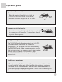
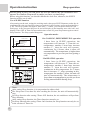
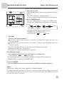
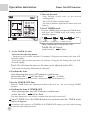
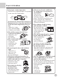
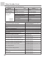
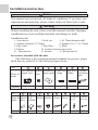
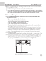
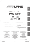
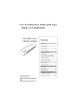
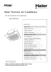
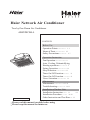
Haier Network Air Conditioner
Two by One Room Air Conditioner
AB422BCBAA
CONTENTS
Before Use
Operation Points*********** 1-2
Name of Parts************* 3-5
Safety Precautions********** 6-7
N o . * 0010571740
Operation Instruction
Fan Operation************** 8
Auto, Cooling, Dehumidifying,
Heating operation************ 9
Swing Operation************ 10
Sleep Function************* 11
Timer On/Off Function******** 12
Timer On-Off Function ******** 13
Usersí Attention************ 14
Maintenance
Maintenance *************15-19
Troubleshooting*********** 20-21
Installation of Indoor Unit
Installation Instruction****** 22
Installation Procedure ****** 24*34
Other Instruction and Test Run****
Please read this manual carefully before using
Please keep this manual for future use
* 23
35
Characteristics of Products
Characteristics of Products
1.Four-direction air sending, more even temperature adjustment.
2.Inner hidden type installation, space-saving; harmonized with the ceiling,
exquisite and beautiful.
3.Powerful circular air volume, quick temperature adjustment.
4.This air conditioner has POWER FAILURE RESUME FUNCTION.
5.Anti-bacteria mildew resistant air filter, fresher air creates more healthy.
6.This unit has the function of far distance monitoring. Through the telephone
network, it can be effectively controlled in any other far-distance place.
(Only after equipped with the ìfar distance detectorî made by our company can
this function be fulfilled.)
Far distance monitoring
There is a pre-set far distance control communication interface on the control
panel of indoor unit. After installing the peripheral equipment according to the
manual attached with the Haier made far distance control detector, the computer
management or other place monitoring can be achieved to the air conditioner.
Operation points
Operation of air conditioner
When the ambient humidity is too high, in
COOLING or DEHUMIDIFYING mode,
there may be water dropped in the air outlet.
3-minute protection function
If start the unit immediately only after it is turned off,
the compressor will start after 3 minutes have elapsed
to protect the compressor.
Change of fan speed
In COOLING mode, the air sending is set at AUTO,
when the indoor temperature is near the set
temperature, the fan speed will lower automatically.
In HEATING mode, when room temperature reaches
the set temperature, the compressor will stop running,
and the fan will change to LOW FAN or stop.
In DEHUMIDIFYING mode, the fan speed will change
automatically.
Far distance monitoring
There is a pre-set far distance control communication interface on the
control panel of indoor unit. After installing the peripheral equipment
according to the manual attached with the Haier made far distance control detector, the computer management or other place monitoring can
be achieved to the air conditioner.
1
Operation points
Anti-cold air blowing out
During Heating operation, after starting the unit,
the indoor fan motor will not rotate immediately
to prevent cold air from blowing out.
Please wait
?
Defrosting function
During Heating operation, when frost formed on the
heat exchanger of outdoor unit, the air conditioner
will defrost automatically for several minutes. During
defrosting, both the fan of indoor and outdoor unit
do not run. After finishing defrosting, the air
conditioner will automatically resume operation.
Hint
When the air conditioner is in Heating mode,
it absorbs heat from outside and release to
indoors. So the outdoor temperature may
affect the Heating effect.
Power failure resume function (please set and use this function
according to actual condition)
After setting power failure resume function, if there is a sudden power
failure during unit operation, when power on for again, the unit will
resume the previous state.
Setting method: when the remote controller is in ON state (except for
TIMER and FAN mode), press the SLEEP button for 10 times in 5
seconds, after the buzzer sounds 4 times, the unit will change to POWER
FAILURE RESUME function.
Cancellation method: press the SLEEP button 10 times in 5 seconds,
after the buzzer 2 times, the POWER FAILURE RESUME function is
cancelled.
Note: After the unit is set POWER FAILURE RESUME function, if there is a
sudden power failure in using, during this period of time if there is no need to use
the unit for a long time, please cut off power to prevent the air conditioner from
automatically resuming to the previous setting if power failure resumes, or press
the ON/OFF button to turn off the unit after power failure resumes.
2
Name of Parts
Indoor Unit
Drainpipe
Louver
(inside of air outlet)
Connection pipes
and electric wire
Air outlet
Air filter
(inside of air inlet grille)
Remote control signal
receiving window
Air inlet grille
Drain
Timer
Operation Power
Wire Controller
MODE
FAN
SWING
AUTO
TEMP
SET
CLOCK
SET
TIMER
SLEEP
ROOM
HEAT FILTER RESET
ON/OFF
RESET
Name of Parts
Wire Controller
14 15 16 17 18
19
21.Clock button
13
12
Used to calibrate the time of
timer and clock
11
10
9
8
7
6
MODE
FAN
5
4
CLOCK
SET
TIMER
SLEEP
ROOM
3
FILTER RESET
RESET
ON/OFF
2
1
1.ON/OFF button
Used to turn on/off unit
2.Temperature display
3.Clock display
4.Timer ON/OFF display
5.Humidity display
6.Air filter cleaning display
When there is too much dust
collected on the air inlet, the
wire controller will show
this display to remind the
user to clean the air inlet.
After cleaning and installation,
*
just press the air filter reset button.
21
22
23
24
25
26
27
28
12.Humidifying state display
13.Sleep state display
14.Network control display
15.Working mode display
16.Electric heating display
Used to set Sleep state or
Power Failure Resume
Function
24.Time Adjusting button
Used to adjust the time of
timer and clock
25.Reset button
When the wire controller
appears abnormal
condition, use a sharppointed article to press
this button to make the
wire controller resume
normal
26.Air Filter Reset button
Used to set working mode:
Auto, Cooling,
Dehumidifying,
17.Operation
mode
button
Heating, Fan
19.Swing button
9.Auto Swing display
10.Health state display
11.Fresh air state display
23.Sleep button
Working Auto
Cooling Dehumidifying Heating Fan
mode
operation operation operation
operation operation
Wire
controller
7.Super/Soft operation display 18.Fan speed button
Used to set fan speed: Low
8.Fan speed display Auto
Fan, Med Fan, High Fan, Auto
Low Fan Med Fan High Fan Auto
Used to confirm the time
of timer and clock
20
TEMP
SET
22.Setting button
SWING
AUTO
Used to set Auto Swing or
Fixed air sending direction
20.Temperature Setting button
Used to set temperature,
temperature range: 16*~30*
After cleaning the air inlet,
press this button, the unit
can start to operate
27.Timer button
Used to set the mode of
timer
28.Lock state display
Note:
This model does not
have the following
related display and
function * * 10 11 12 28
Calibration of clock
When turning on the unit for the first time, the clock should be calibrated. The method
of calibration is:
1.Press ìClockî button, the Clock display ìAMî ìPMî will flash.
2.Press * or * to adjust time. For each press, the time will increase or*decrease 1
minute. If depressing the button, the time will increase or decrease*rapidly.
3.After confirming the time, press ìSetî button, ìAMî or ìPMî will stop flashing, the
clock will begin to work.
4
Safety Precautions
Please read the following Safety Precautions carefully and use
the air conditioner properly.
The following lists four kinds of safety precaution items and suggestions:
Warning: Improper use may cause death or serious injury.
Notice: Improper use may cause body hurt or unit damage; in some
circumstance, it may cause serious results.
: Those contents marked with ìProhibitionî are definitely prohibited action,
otherwise, it may cause unit damage or risk to usersí safety.
********************
: Those contents marked with ìForcedî are definitely forced action, otherwise, it may cause unit damage or risk to usersí safety.
The following safety precautions must be observed.
This safety precautions should keep in hand for reference.
When transfer the air conditioner to a new user, this manual should also be given
to the new user together with the unit.
!
If abnormal conditions (sear smell)
occur, please stop the unit, turning
off the electric power and contact the
after-sales service center for solution.
Cut off
power
When needing repair, please ask the
after-sales service work for help.
Improper maintenance and
repair may cause water
leakage, electric shock and fire.
During the unit operation, do not
insert fingers or other articles alike
into the air inlet, outlet and louver.
Because the high-speed
fanis very dangerous,
it may cause hurt.
Warning
Ask after-sales service worker to take
measure to prevent refrigerant from
leaking.
If the leaked
refrigerant exceeds
a certain density, it will cause lack of
oxygen. If the room installed with air
conditioner is too small, do take enough
measure in order to avoid lack of oxygen
even if refrigerant leaks.
When the air conditioner must be
dismantled and reinstalled, please ask
the after-sales service center to do this
work.
Improper installation may cause water
leakage, electric
shock and fire.
5
Safety Precautions
Notice
Do not use wet hands to
operate the air conditioner.
Otherwise, it may cause
electric shock.
Do not use water to
clean air conditioner,
otherwise may cause
electric shock.
Only use the proper
specified fuse. Do not
use cable or other
materials to replace the
fuse, otherwise it may
cause fire and other
trouble.
Connected with the grounding wire.
The grounding wire shouldnít be connected
with gas pipe, tap water pipe, lightning rod
or telephone line. Improper grounding may
cause electric shock accident.
The drain hose should be arranged
properly to have a smooth drainage.
Do not put the fire devices in the
places, which the air from the air
conditioner can directly blow.
It may cause the fire
devices cannot burn
completely.
Do not put or use any
spray near the air
conditioner, otherwise
it may cause fire.
Do not install the air conditioner in a
place where the inflammable gas
maybe exists.
The inflammable gas around the air
conditioner may cause fire accident.
The Creepage breaker should be
equipped.
Only after cutting off the power, can
the cleaning of the air conditioner be
performed to avoid leading to electric
shock or injury.
Not in
operation
6
If the drain hose is not arranged properly,
the leaked drain water may damage the
furniture or other articles alike.
When using indoor smoky type
pesticide, do not use air conditioner.
Otherwise, it may cause the chemicals
accumulate in the unit, result in doing
harm to the peopleís
health who is
extremely sensitive
to these chemicals.
Operation instruction
Fan operation
1 Turn on the unit
MODE
2
FAN
TEMP
Press the ON/OFF button to turn on the unit
The LCD display of the wire controller will
show the previous working state (except for
Timer, Sleep, Swing mode), the operation
indicator light on the wire controller will
light up.
SWING
3
CLOCK
SET
TIMER
SLEEP
HEAT FILTER RESET
RESET
2 Choose of working mode
ON/OFF
1
4
Press MODE button, each press the working
mode will change as the following sequence:
AUTO
COOLING
DEHU
HEATING
FAN
choose FAN operation
3 Adjusting FAN SPEED
Press the FAN SPEED button to change fan
speed:
LOW FAN
MED FAN
HIGH FAN
Choose the desired fan speed
4 Turn off the unit
Press the ON/OFF button to turn off the unit.
The wire controller only shows the clock and
room temperature.
About FAN operation:
FAN operation refers the air conditioner does not perform COOLING and
HEATING operation, but FAN operation. In this mode, the air conditioner
cannot perform AUOT FAN operation, and does show the temperature value
on the wire controller.
7
Operation instruction
Auto/Cooling/Dehumidifying/Heating operation
1 Turn on the unit
2 MODE
FAN
TEMP
SET
Press the ON/OFF button to turn on the unit
The LCD display of the wire controller will
show the previous working state (except for
TIMER, SWING, SLEEP mode). The
operation indicator light on the wire controller
will light up.
SWING
4
3 CLOCK 3
SET
TIMER
SLEEP
2 Choose of working mode
Press MODE button, each press the working
mode will change as the following sequence:
HEAT FILTER RESET
RESET
5
ON/OFF
1
AUTO COOLING DEHUMIDIFYING HEATING FAN
then choose AUTO, COOLING,
DEHUMIDIFYING, HEATING operation.
When
room
temperature is higher
than set temperature,
unit in COOLING
operation.
3
Set temperature
Press the TEMP. SET button
Ultra-low air flow
Set temperature + 2*
Set temperature
When room temperature
reaches set temperature
+ 2*, the unit will operate
in mild dehumidifying
operation.
In Heating operation, after start the
unit, the air conditioner will sending
warm air a moment later to prevent
the cold air blowing out. In
Dehumidifying, when the room
temperature drops 2* higher than
the set temperature, regardless the
set fan speed, the air conditioner
will intermittently operate in low
fan speed.
*Each press , the set temperature will
increase 1 degree.
*Each press, the set temperature will
decrease 1 degree.
Set the desired temperature.
4 Adjusting FAN SPEED
Press the FAN SPEED button, for each press,
the fan speed will change as the following
sequence:
AUTO
LOW FAN
MED FAN
HIGH FAN
AUTO
Choose the desired fan speed.
5 Turn off the unit
Press the ON/OFF button to turn off the
unit.
The wire controller only shows the clock
and room temperature.
Hints:
The wire controller can memorize the working condition of each time. When start the unit for the second
time, just need to press ON/OFF button, the air conditioner will work according to the previous working
mode. (except for Timer, Sleep and Swing)
8
Operation instruction
Swing
Auto swing
MODE
FAN
SWING
TEMP
SET
CLOCK
SET
TIMER
SLEEP
Press SWING button, the LCD of the remote
controller display ì
î, the louver of the air
conditioner begins automatic swing and air sending.
HEAT FILTER RESET
RESET
ON/OFF
Fixed air sending direction
When the Auto SWING of the air conditioner
swings to an appropriate angle, press SWING
button, the display ì î on the LCD of the remote
controller will disappear, the air sending direction
is fixed.
When fixing the air sending direction, the louver
should be kept in the following position:
In COOLING and DEHUMIDIFYING, it is better
to be upward.
In HEATING, it is better to be downward.
Always use the SWING button of the remote controller to adjust
the louver. If adjust the louver manually, it may damage the
louver.
During COOLING and DEHUMIDIFYING, do not make the
louver downwards for a long time. Because the vapor around
the air outlet grille may be condensed and may have drop of
water.
When the infant, children, ages and the patients use the air
conditioner, please pay attention to the set temperature.
9
Operation instruction
Sleep operation
Before going to bed, you can press the SLEEP button, the air conditioner will
operate in comfort sleep mode to make you have a sound sleep.
Before using this function, you should calibrate the clock first, otherwise, the SLEEP
function will be out of order.
Use of SLEEP function
After turning on the unit, setting the working mode, then press SLEEP button to make the air
conditioner have the previous Sleep time (powered on for the first time or after performing Sleep
is 1h). The Sleep symbol will appear. Press time */* button, you can choose between 1~8h.
Each press, it may increase/decrease 1h and will display in the humidity area with ìxhî, and
display ìTimer Offî in Timer Off area and the time to turn off; press Sleep button again to cancel
Sleep function. The Sleep symbol disappears.
Operation modes
SLEEP operation stops
SLEEP operation starts
about 6 hours
increase 1*
1 hour
increase 1*
1 hour
Set temperature
turn off
in COOLING* DEHUMIDIFYING operation
Set temperature
1 hour
turn off
decrease 2*
1 hour
decrease 2*
about 3 hours
3 hours
SLEEP operation starts
increase 1*
SLEEP operation stops
in HEATING operation
MODE
FAN
SWING
TEMP
SET
CLOCK
SET
TIMER
SLEEP
HEAT FILTER RESET
RESET
1.In COOLING, DEHUMIDIFYING operation
1 hour later in SLEEP operation, the
temperature will increase 1* from the set
temperature, another 1 hour later increase
another 1*, then the unit will operate
continuous for 6 hours, then it turns off
automatically. The temperature is higher than
set temperature to prevent you from getting a
cold.
2.In HEATING operation
1 hour later in SLEEP operation, the
temperature will decrease 2* from the set
temperature, another 1 hour later increase
another 2*, then the unit will operate
continuous at this temperature for 3 hours,
then it increases 1*, after operating at this
temperature for another 3 hours, the unit will
turn off automatically. The temperature is
lower than set temperature to prevent you from
feeling uncomfortable during sleep.
ON/OFF
Note:
After setting Sleep function, it is not permitted to adjust clock.
The Sleep time is less than 8h, after reaching the set time, the unit will automatically
stop.
Set Sleep function after setting ìTimer Offî function, the air conditioner will perform
Sleep function.
After setting Sleep function, the Timer function cannot be set.
Set Sleep function after setting ìTimer Onî function, the Sleep function can only be set
in the set time of Timer On.
10
Operation instruction
Timer On/Off function
Before using TIMER function, calibrate the clock first.
MODE
FAN
SWING
TEMP
1.Turn on the unit
After turning on the unit, set the desired working
mode.
The LCD will show working mode.
The power indicator light on the indoor unit will light up.
SET
CLOCK
SET
TIMER
SLEEP
HEAT FILTER RESET
RESET
ON/OFF
2.Set of TIMER mode
Press the TIMER button to change the TIMER mode,
each press the TIMER mode will change as the following
sequence:
OFF
ON
TIMER ON
ON
OFF
AM
AM
TIMER OFF
Blank
PM
PM
TIMER ON-OFF
Then choose the timer mode as need
(TIMER ON or TIMER OFF.)
At this time the*
ON*or *
*will
OFF
flash.
3.Set time
Press the time adjusting button
Each press, the set time increases 10 minutes. If depress the button, the time will
increase rapidly.
Each press, the set time decreases 10 minutes. If depress the button, the time will
decrease rapidly.
This LCD will show the time set, the time can be adjusted within 24h.
(The minimum interval is 10 minutes).
AM stands for morning, PM stands for afternoon
4.Confirm the time
After calibration of the clock, press SET button to confirm time.
At this time, the* ON*or* OFF
*will not flash.
The time displayed is: at x oíclock x minutes the unit will be turned on
(TIMER ON) or turned off (TIMER OFF).
5.Cancel TIMER
Press the TIMER button several times until the TIMER mode display disappears.
Hints:.
After power failure, the clock should be calibrated again.
The remote controller has memory function, when you use this function for the second time,
if the time set is the same as the previous one, you just need to choose the TIMER mode then
press the SET button to confirm.
11
Operation instruction
Timer On-Off function
Before using TIMER function, calibrate the clock first.
1.Turn on the unit
MODE
FAN
After turning on the unit, set the desired
working mode.
The LCD will show working mode.
The power indicator light on the indoor unit will
light up.
SWING
TEMP
SET
CLOCK
SET
TIMER
SLEEP
6
5
HEAT FILTER RESET
RESET
ON/OFF
2.Set of TIMER mode
Press the TIMER button to change the TIMER mode,
each press the TIMER mode will change as the
following sequence:
ON
AM
TIMER ON
3.Set the TIMER ON time
OFF
ON
AM
TIMER OFF
OFF
Blank
PM
PM
TIMER ON-OFF
Then confirm the Timer mode is the
TIMER ON-OFF mode.
At this time the* ON*will flash.*
Press the time adjusting button
Each press, the set time increases 10 minutes. If depress the button, the time will
increase rapidly.
*Each press, the set time decreases 10 minutes. If depress the button, the time will
decrease rapidly.
*
This LCD will show the time set, the time can be adjusted within 24h.
*AM stands for morning, PM stands for afternoon*
4.Confirm the time
After adjusting time, press SET button to confirm time.
At this time, the * ON*will not flash, *
*OFF
begins to flash.
The time displayed is: at x oíclock x minutes the unit will be turned on.
5.Set the TIMER OFF time
Press the TIME button, the adjustment method is the same as
ON time.
the one of setting TIMER
6.Confirm the time of TIMER OFF
After adjusting time, press SET button to confirm time.
At this time, the * OFF*will not flash.
The time displayed is: at x oíclock x minutes the unit will be turned off.
Cancel TIMER: Press the TIMER button several times until the TIMER mode
display disappears.
According to the sequence of TIMER ON & TIMER OFF setting, you can realize turning
on unit first, then turning off unit.
12
Usersí Attention
Set proper room temperature
Not too low or high and make every people
in the room feel comfortable.
Cooling is
26~28*
Heating is
18~23*
Do not let the cold air blows directly to
human body for a long time and do not
make the room temperature drop too
low.
Otherwise, it may
cause uncomfortable
or bad to your health.
The airflow cannot directly blow
to the pets and plants.
Otherwise, pets
and plants
may be hurt.
The room should often ventilate.
After a long-time
of using air
conditioner, the
room must be
ventilated.
Do not keep the doors and windows
open
Otherwise, it
may lower the
efficiency of
the air conditioner.
Television, radio and acoustics, etc.
equipment should keep over 1m from
indoor unit and wire controller.
Otherwise, they may
disturb the image
and cause noise.
Do not put any drying
devices under
the indoor unit.
The heat may cause
the deformation of
indoor unit.
If do not use the air conditioner
for a long time, it is necessary to
cut off power.
If do not cut
Cut off
power supply
off power, the
unit may consume
power. In order to protect the unit,
before using the air conditioner
again, turning on the power at least
12 hours in advance.
The windows should be hung
with curtains or blinds.
Do not let the sun
shine directly shine
in the room; do not
let the outdoor air
enter room.
The articles must keep dry cannot
be put under the indoor unit.
When the humidity
is over 80% or
the drainage
outlet is blocked,
the indoor unit may drop water.
Do not put articles around the
air inlet and outlet.
This kind of obstacle can lower the
efficiency of the air conditioner or
cause unit trouble.
The air conditioner can only be used
in air conditioning. It can not be
used in other purpose.
Do not use the air conditioner in some
specific purpose, such as storage or
protect food, animals, plants, precise
instrument and
artwork,
otherwise,
the quality
of them may
be declined.
13
Maintenance
Notice
The repair can only be performed
by the professional workers.
Before touch the wire connection
device, cut off the power first.
Notice
Only after turning off the unit and
cutting off the power can the
cleaning of the unit be performed.
Otherwise, it may cause electric
shock or injury.
Donít in
operation
Do not use water to clean the air
conditioner.
Otherwise, it
may cause
electric
shock
Use stable stand support.
Please pay high attention when
cleaning the unit
Daily maintenance
Clean the air filter
Instructions:
When not for cleaning, do not dismantle the air filter, otherwise it may
cause trouble.
When the air conditioner is used in a dusty environment, the air filter should
be cleaned more often (generally once every two weeks).
Open
1.Open air inlet grille
Pull the two handles at the same time,
slowly draw them out. (when closing
it, the procedure is reversed.)
14
Maintenance
Clean the air filter
2.Dismantle the air filter
Pull the two side handles at the
back of the air inlet grille, lift the
air filter to dismantle it.
Open and remove
3. Clean
Notice
Do not use the hot water over 50* to clean to avoid discoloration or
deformation.
Do not dry the unit on fire, the filter may be burnt.
Use cleaner or water to clean to remove dust.
*A*Use
cleaner to remove dust.
*B*When
the dust is too much, use
soft brush and neutral detergent.
*C*Throw
the water off, then put it
in the shadow for airing.
4. Install air filter
(1)Put the air filter into those extruding parts at the top of the air inlet grille.
(2)Draw the handles at the back of the air inlet grille inwards to fix the air
filter.
5.Close air inlet grille
Referring to procedure 1.
15
Maintenance
Clean the air inlet grille
1.Open air inlet grille
Pull the two handles at the same
time, slowly draw them out. (when
closing it, the procedure is reversed.)
Open
2.Remove air filter
Referring to ìClean the air filterî.
3.Remove the air inlet grille
Open the air inlet grille for 45o, the
lift it up.
4.Clean
Notice
Do not use the hot water over 50* to clean to avoid discoloration or
deformation.
Use soft brush, water and neutral
detergent to clean, then throw the water
off.
Instruction
there is too much dust*
Use ventilation fan or directly spray the detergent special for kitchen
ware on the air inlet grille, 10 minutes later use water to clean.
*When
5. Install air inlet grille
Referring to procedure 3.
6.Install the air filter
Referring to ìClean the air filterî
7.Close air inlet grille
Referring to procedure 1.
16
Maintenance
Clean the air outlet and casing
Notice
Do not use gasoline, benzene, diluent, polish powder or liquid pesticide
to clean.
Do not use the hot water over 50* to clean to avoid discoloration
or deformation.
Use soft dry cloth to clean.
If cannot remove the dust, use water or neutral detergent.
If the louver of the air conditioner is too dirty, it may be dismantled (as
the following described) for cleaning.
Dismantle and install louver
1.Fix the louver at the lowest position.
Referring to SWING operation.
2.Dismantle louver
Notice
When use water to clean the louver, do not clean it to hard, otherwise
the fuzz on the surface maybe fall off.
Loosen the screws at the two ends of the louver.
3.Install louver
Slightly rotate the louver, the
extruding edges at the ends of the
air inlet can be inserted into the
louver groove, then tighten the
screws.
Instruction
For details, please consult the after-sales
service worker.
17
Maintenance
Maintenance before and after the using season.
Before using season
1.Check the following items:
If the air inlet and outlet of indoor and outdoor unit are blocked.
If the earth wire is proper.
If the wire connection is proper.
If there is abnormal phenomenon, please ask the after-sale
service staffs for help.
2.Cleaning the air filter or air inlet and casing
After cleaning the air filter, it must be reinstalled.
3.Turn on the power
After using season
1.In a sunny day, perform half-a-day Fan operation to make the
inner of the unit dry.
2.Cut off the power
If do not cut off power, the unit will consume power. Power
cutoff can save power.
3.Cleaning the air filter or air inlet and casing
After cleaning the air filter, it must be reinstalled.
For the details of cleaning, please refer to Maintenance.
18
Troubleshooting
The following phenomena are not troubles
Symptom
The unit does Immediately operate the
not work
unit after its stop.
In COOLING operation,
The unit when the ambient humidity
blows out is too high. (the content of
mist.
oil or dust is too much in
the room.)
After
finishing
DEFROSTING, the
HEATING operation starts.
In COOLING or
DEFROSTING, there is
continuous ìSi, Siî noise.
When the unit is started,
stopped and when
The unit
DEFROSTING starts or
gives out
stops, there is the ìSi, Siî
noise
sound.
In operation or after
operation, there is a
continuous ìSi, Siî sound.
Cause
3 minutes later, the unit will
automatically operate.
When the inner of the indoor unit is
not clean, the temperature fluctuation
may occur.
The removed frost rises in vapor state.
This is the refrigerant gas flowing sound
in the air conditioner.
It is generated when the refrigerant
stops flow or changes flow.
It is the operation sound of the drainage
system. (in COOLING operation, the
drainage system drains in indoor side.)
In operation or after Because of the temperature change, It
operation, a ìGaZhiî sound is caused by the hot expansion and cold
shrink of the resin parts.
is generated.
The unit
After a long-time out of
blows out
use, the unit is started.
dust
The unit gives
out smells.
In operation.
In DEHUMIDIFYING, no air
sent out or cannot change the
fan speed.
The dust in the indoor unit assembly
is blown out.
The smells or the cigarette smell
absorbed in indoor unit are blown out.
In DEHUMIDIFYING operation, when the room
temperature is 2* higher than the set temperature,
despite of the set FAN SPEED the air conditioner
will operate in LOW FAN SPEED.
19
When Troubles Occur
Before contacting the commissioned repair center for after-sales service, please check your
air conditioner according to the following items.
Symptom
The unit does not
operate.
Once the unit operates, it
stops immediately.
Abnormal
COOLING
HEATING.
of
or
*COOLING*
*COOLING*
*COOLING*
Cause
The fuse is blown out or the breaker
is open.
The air inlet or air outlet of indoor
or outdoor unit is blocked.
The air inlet or air outlet of indoor
or outdoor unit is blocked.
Improper set temperature
The fan speed is set too low
Incorrect swing direction
The doors or windows are open
Direct sunshine
Too much people in room
Too many heat sources in room
Solution
Change the fuse or close the
breaker.
Remove the obstacles.
Remove the obstacles.
Referring to page 8
Referring to page 8
Referring to page 9
Close them
Hang the curtain or blinds before
windows
Trouble display
Phenomenon of outdoor unit trouble
The trouble of outdoor ambient temperature sensor
The trouble of outdoor coil temperature sensor
The trouble of outdoor discharging air temperature
sensor
The outdoor discharging air temperature is too high
Over electric current protection
CT wire breaks
Detection of abnormal phase sequence
The communication trouble between indoor and
outdoor unit
The protection of too high (too low) pressure
The flashing time of indicator light on
outdoor control panel
1 (A, B systems indicate together)
2 (A and B system indicate individually)
3 (A and B system indicate individually)
4 (A and B system indicate individually)
5 (A and B system indicate individually)
6 (A and B system indicate individually)
7 (A and B system indicate together)
8 (A and B system indicate individually)
9 (A and B system indicate individually)
Trouble indication on remote control
Phenomenon of indoor unit trouble
type indoor unit
The compressor indicator light flashes 1 time
The trouble of indoor ambient temperature sensor
in 0.2S/time frequency
The compressor indicator light flashes 2 time
The trouble of indoor coil temperature sensor
in 0.2S/time frequency
The compressor indicator light flashes 3 time
The trouble of outdoor ambient temperature sensor
in 0.2S/time frequency
The compressor indicator light flashes 4 time
The trouble of outdoor coil temperature sensor
in 0.2S/time frequency
The compressor indicator light flashes 5 time
The trouble of electric current overload
in 0.2S/time frequency
The compressor indicator light flashes 6 time
Over voltage protection
in 0.2S/time frequency
The compressor indicator light flashes 7 time
Excessive and lack voltage protection
in 0.2S/time frequency
The communication trouble between panel and indoor The compressor indicator light flashes 8 time
panel
in 0.2S/time frequency
The communication trouble between indoor panel and The compressor indicator light flashes 9 time
in 0.2S/time frequency
outdoor panel
The compressor indicator light flashes 10 time
The trouble of water pump
in 0.2S/time frequency
20
Installation instruction
Before installing, do read this ìSafety precautionsî carefully to guarantee the proper installation.
The below attentive matters are divided into ì Warningî and ì Noteî two parts. When the wrong
installation occur, it is very possible death and severe injury and other serious accidents will happen. For
those items are listed in ì Warningî part. But even the items listed in ì Noteî part can also cause serious
accidents. Above all, both the two parts are very important contents related to safety, so they must be obeyed.
After finishing the installation work, do test run to verify everything is normal. After that please explain the
using and maintenance methods to the user. Additionally, give this installation manual and operation manual
to the user and ask them to keep it properly.
Warning
The commissioned repair center shall do the installation work. If you do the installation work by yourself,
the improper installation will cause water leakage, electric shock fire and other accidents.
The installation work shall be in line with what the installation manual specified. If installation is not
proper, water leakage, electric shock, fire and other accidents will occur.
Install the air conditioner to a place where can definitely stand its weight. The air conditioner can not be
installed on a nonmetal bracket (such as theft guard net). Places not firm enough will cause drop down of
unit resulting in body hurt.
The installation work shall be preventive to typhoon and earthquake. If the installation work is not met
with the requirements, overturn of the unit will occur resulting in accidents.
Using the specified cable to do wiring work and connecting firmly and properly. Fix the connecting part
of the terminals to prevent it from the external force. Improper connection and fixing will cause heating
and fire etc. accidents.
Wiring shall be kept in correct shape avoiding extrusion. After installation, the electric box cover and the
external panel shall not nip the wire. Improper installation will cause heating and fire etc. accidents.
When setting or moving the air conditioner do not let the air and things alike get into the refrigeration
system except the specified refrigerant (R22). If air and other things enter, abnormal high pressure will
occur, which easily cause break and body injuries etc. accidents.
When installing, do use the accessories or specified parts. If not using the parts specified by our company,
water leakage, electric shock, fire and refrigerant leakage will occur.
Do not lead the drain hose to drain where the sulfur gas may be involved. Otherwise, the poisonous gas
will enter into the indoor.
During installation, if refrigerant leakage occurs, do the ventilation work immediately. As soon as the
refrigerant gas meets fire, poisonous gas will be produce.
After installation, confirm there is no leakage of refrigerant. If the refrigerant gas enters into room and
meet the air blowing heater, heater or stove etc. fire source, the poisonous gas may be produced.
Do not install the unit in a place where the combustible gas may be leaked. In any case the combustible gas
leaks and accumulated around the unit, fire accident will occur.
The drain hose should be correctly installed according to the installation manual to ensure smooth drainage,
and take proper heat preservation measure to prevent from dew. Improper pipe installation may cause water
leakage result in wet the indoor articles.
Do heat insulation work to the refrigerant gas pipes and liquid pipes to reach the purpose of heat preservation.
If the heat insulation measure is not sufficient, water generated by condensing dew will drip leading to wet
the floor and indoor articles.
Note
Do grounding work. Do not connect the grounding wire to gas pipe, tap, lighting rod or telephone line.
Improper grounding will cause electric shock.
In some places the creepage breaker shall be installed. If do not install the breaker, electric shock may occur.
After electric installation, power on them to do electric leakage test.
21
Installation instruction
Notice
This manual can not include all kinds of conditions, if you have new
requirements and questions, please contact with local Haier Sales Center.
Warning
Before installing the unit, please read this manual carefully. Improper
installation may cause accidents and make unit damage or death.
Installation tools
1. Screwdriver
2. Steel saw
3. 60, 70mm diameter drill
4. Spanner (diameter 17,27mm)
5. Spanner (14, 17, 19, 27mm)
6. Pipe cutter
7. Pipe flarer
8. Knife
9. Pincers
10. Leakage detector/soap water
11. Tape measure
12. Scraper
13. Refrigerant oil
Accessories attached with the unit
The following is the manual mentioned standard accessories, please
check them by yourself. As the following figure shown
No.
1
3
2
4
5
6
Wire controller Signal Installation Little wire Big wire
clamp
Shape & (signal wire) wire paper panel clamp
name
**
AUTO
**
Thermal
insulation
pipe
**
**
**
**
**
**
**
**
**
****
**
MODE
FAN
SWING
**/**
AUTO
TEMP
HEALTH
CLOCK
SET
SET
TIMER
SLEEP
ROOM
No.
1
1
Amount
7
8
9
1
10
Gasket Buckle
Shape & Drain Seal
hose cushion
name
Amount
22
1
4
8
1
6
11
Screw
3
AUX.H
FILTER RESET
12
2
2
13
14
Refrigera Cement
Plastic nt oil
steel nail
6
1
12
Installation procedure
Install indoor unit
1. Before installation [Before finishing installation, do not throw the attached
parts installation needs]
Confirm the way to move the unit to the installation place.
Before moving the unit to the installation place, do not remove their packages.
When have to remove the package, use a soft material or protection board with
rope to lift the unit assembly to avoid unit damage or bumping a scrape.
2. Choose installation place
300
(1)The chosen installation place should meet the following requirements and
get the userís consent.
Place ensures ideal airflow distribution.
The passage of airflow has no obstacles.
The condensate water can be drained smoothly.
Place can stand the weight of indoor unit.
Place ensures enough space for maintenance.
The pipe length between indoor and outdoor unit is in the permitted limit
(referring to outdoor unit installation part).
The indoor unit, outdoor unit, electric wire and connection wire is at least
1m away from television and radio. This is to avoid the image disturbance
and noise caused by the above-mentioned home appliance. (Even if 1m
away, if the electromagnetic wave is too strong, it can also cause noise.)
(2)The height of ceiling
The indoor unit can install on the ceiling, which height is no more than 2.7m.
(3)Install and use the hoisting screw. Check if the installation place can bear the
weight of unit assembly. If not certain, strengthen it before install the unit.
(The installation gaps are marked on the installation paper panel. Refer to
the paper panel to find those points needing to be strengthened.)
Over 1500
Over 1500
Air inlet
Air discharging hole
Loud 1000
Air discharging hole
Space installation needed (unit: mm)
23
Installation procedure
Install indoor unit
3.Preparation before installation
Hoisting angel iron
780 (The distance
between hoisting screws)
840 (Indoor unit assembly)
950 (Decorative panel)
890*(Ceiling opening)
(1) The position relation among ceiling opening and hoisting screws (unit: mm)
Refrigerant pipe
Ceiling
A direction
Over 20
Hoisting screw
1070 (The distance
between hoisting screws)
840 (Indoor unit assembly)
1280*(Ceiling opening)
1340 (Decorative panel)
A
(Instruction)
The dimension of the ceiling
opening with the mark of * can
reach 910mm, but the overlap
part between ceiling and
decorative panel should keep
over 20mm.
(2) If necessary, cut the opening installation needed in the ceiling.
(For the condition of having ceiling)
For the dimension of the ceiling opening, please refer to the installation paper
panel.
Before installing the unit, finish the work of all the pipes (refrigerant pipe, drain
hose) and wire (connection wire of indoor and outdoor unit) connected with
indoor unit to make it is possible after installation, they may connect with the
indoor unit immediately.
If cutting a opening in the ceiling, maybe the ceiling needs to be strengthened
to guarantee its evenness and prevent the ceiling from vibration. For details,
please consult to the builder.
(3) Install the hoisting screw (use a M10 screw)
(The using specification of hoisting screw is M8, but when the height of
hoisting screw is more than 1.0m, the hoisting screw with the specification
of M10 must be used).
In order to bear the weight of the unit, for the original ceiling circumstance,
use foot screw; for the new
<The example of actual installation>
ceiling circumstance, use
Roof
built-in screw, embedded
Screw
screw or the parts provided
Long screw nut or threaded bolt
on site.Before continuing
Hoisting screw (M8 or M10)
installation, adjust the gap
Ceiling
between the unit and the
ceiling.
24
Installation procedure
Install indoor unit
4.Installation of indoor unit
In the new ceiling circumstance
(1)Temporarily install the indoor unit
Attach the hoisting foot on the hoisting screw. The screw nut and washer
must be used at the top and bottom two ends of the hoisting foot to make
the hoisting foot firm.
(2)For the dimension of the ceiling, please refer to the installation paper panel.
There is the mark of the ceiling openingís center on the installation paper
panel.
There are marks of the unit center in both the label attached on the unit
and the installation paper panel.
Use screws to fix the installation paper panel on the unit, and use screws
to fix the corners of the drain pan at the end of the pipe outlet.
After finishing installation of the ceiling
(3)Adjust the unit to the correct installation position.
(4)Check if the unit is level
The indoor unit is equipped with internal drainage pump and float switch.
Use water level or the polyethylene pipe charged with water to respectively
check if the four corners of the unit are level. (If the unit is slant toward
the opposite direction of the condensate water flow, the float switch may
have trouble leading to water leakage.)
(5)Fasten the screw nuts on the washer.
(6)Dismantle the installation paper panel.
In the original ceiling circumstance
(1) Temporarily install the indoor unit
Attach the hoisting foot on the hoisting screw. The screw nut and washer
must be used at the top and bottom two ends of the hoisting foot to make
the hoisting foot firm.
Screw nut (provided on site)
(2) Adjust the height and
Washer (accessory)
the position of the unit.
Washer (accessory)
Hoisting foot
(3) Perform the step (4)
Fasten (two screw nuts)
and (5) in the procedure
[fix the washer firmly]
[fix the hoisting foot firmly]
of ìin the new ceiling
circumstanceî.
Use screw to fix one end of the pipe outlet on the corner of the drain pan.
4 edges together
The center of ceiling opening
Installation paper panel
Water level
Hoisting screw
Suspending pole
Screw (accessory)
Screw (accessory)
[Install and fix the installation paper panel]
25
Installation procedure
Install indoor unit
5.Refrigerant pipe
[The proper thermal insulation must be treated to gas pipe and liquid pipe. If
not, it may cause water leakage.]
The outdoor unit is not charged with refrigerant.
When connecting the pipes to unit or dismantling the pipes from the unit,
do proceed as the figure shown, use spanner and torque pincers together.
For the dimension of the cone-shaped screw nut, please referring to
Table 1.
When connecting pipes, both the inner or the outside of the cone-shaped
screw nut should pasted with refrigerant oil. Use hands to twist it for 3~4
circles, then tighten it.
According to Table 1 to confirm the fasten torque. (fasten too tight may
damage the screw nut leading to leakage)
After check if the connection pipes leaks, then perform thermal insulation
treatment, as the following figure shown.
Only use seal cushion to bind the joint between gas pipe and the insulation
parts.
Paste refrigerant oil here
Medium seal
cushion (accessory)
(use seal cushion to
bind the pipe joint)
Torque spanner
Spanner
Pipe joint
Cone-shaped screw nut
Clamp
Thermal insulation part (accessory)
(for liquid pipe)
Thermal insulation part (accessory)
Gas pipe (for gas pipe)
Liquid pipe
Specification of pipe
(mm)
Torque
Dimension of cone
A (mm)
*9.52
3270~3990 Ncm
(333~407 kgf*cm)
12.0~12.4
*15.88
9720~11860 Ncm
(990~1210 kg*fcm)
Cone
45
R0.4~0.8
90
18.6~19.0
2
0.5
A
6.Installation of drain hose
(1)Install the drain hose
The diameter of the drain hose should be larger than or equal to the diameter
of connection pipe.
(Polyethylene pipe, dimension: 25mm, external diameter:32mm)
Installation procedure
Install indoor unit
The drain hose should be as short as possible. The droop slant degree at least
should be 1/100 to avoid forming of gas bag.
If cannot make the drain hose have an enough slant degree, a drainage
enhancing hose should be equipped.
In order not to let the drain hose bend, a 1~1.5m distance should be kept
between suspending frame.
1-1.5m
1/100*****
Incorrect
Correct
Use drain hose (accessory) and buckle (accessory).
Insert the drain hose into the drainage interface till the white adhesive tape
part. Tighten the buckle tight.
In order to thermal insulated, use seal cushion to bind the drain hose.
Do thermal insulation to the indoor drain hose.
Big seal cushion (accessory)
Buckle(accessory)
Adhesive tape (white)
Buckle (accessory)
Drain hose(accessory)
Below 4mm
Wire clamp (accessory)
Below
750
Drain hose (accessory)
Below
75mm
220
Within 300mm 1-1.5m Hoisting foot
Drain hose (accessory)
Drainage enhancing pipe
Below
530
<The attentive matters of drainage enhancing pipe>
The installation height of the drainage enhancing pipe should be less
than 280mm.
The drainage enhancing pipe should be vertical to the unit and no more
than 300mm away from the unit.
Over 100
Instruction)
The slant of the accessory drain hose should be within 75mm to make the
drain faucet not bear too much excessive external force.
If many drain hoses join together, please install according to the following
procedure.
T-joint joined drain hose
The specification of the chosen joined drain hoses should be applicable to the operation
capacity of the unit.
27
Installation procedure
Install indoor unit
Test of drainage system
(a)After finishing the electric work, perform the test to the drainage system.
(b)During test, confirm the water flow properly passes the hose and there is
no leakage at the joint.
(c)If the house is new, perform test before installing ceiling.
(d)Even if installing in the season needing to make heating, the test also must
be performed.
Procedure
(a)Through the air outlet and use water pump to provide the equipment with
about 1000cc water.
(b)In COOLING operation, check the drainage system.
Maintenance cover
Drain hose The drainage
outlet for maintenance
(with a rubber stop)
(use this outlet to
discharge the water in
the drain pan)
Checking hole
Connected with
outdoor unit
Terminals block
of the power
The PC board of
the indoor unit
Terminals block
of the power
100mm
Plastic watering pot
(the pipe should be
about 100mm long)
(Charge through the checking hole)
(discharge through the
air discharging hole)
Electric box cover
7.Electric circuit
All the provided parts, material and electric work should be complied
with the local regulation.
Must use cooper core cable.
When performing electric work, please refer to the wiring diagram on
the unit.
All the wiring work should be done by the qualified electrician.
A breaker which can cut off the power of the whole circuit must be
equipped.
For the specification of the power cable connected with the outdoor unit,
the capacity of breaker and switch and the guide of circuit, etc. please
refer to the configuration of the power supply.
28
Installation procedure
Install indoor unit
<The wiring method of the connection of the unit>
Connect the unit
Remove the electric box cover (1), draw the wire in the rubber lining, use wire
clamp A to clamp it together with other wires, and connect the wire of the
relative polarity to the inner power terminal block.
After proper connection, press the wire clamp A tight.
Bind the seal cushion on the wire. (it must be bound tight to avoid dew-forming)
After proper connection, reinstall the electric box cover (1).
Power terminal block
Power terminal block
Wire clamp A
Grounding wire end
Rubber lining
Electric box cover (1)
This part must be sealed to prevent water from entering
Rubber lining Instruction: Use seal cushion to bind
tight not leaving any gap
Seal cushion (little size) bind the wire
(inside) (outside)
Attached with seal cushion
Wiring on site
29
Installation procedure
Install the decorative panel
1. Preparation of decorative panel
The treatment of decorative panel
The decorative panel cannot be put down with the front downwards,
cannot lean on the wall and cannot be put on the extruding objects.
Do not touch louver or force on it, otherwise the louver may have trouble.
(1) Dismantle the air inlet grille from the decorative panel
Pull the pole of the air inlet grille inwards, then lift one end of the pole
(referring to Figure 1).
Lift the air inlet grille for about 45*, dismantle the air inlet grille from the
decorative panel. Then tear off the adhesive tape to fixing the air filter on
the back of the air inlet grille (referring to Figure 2).
45
Adhesive tape (4 positions)
Pole
Figure 1
Figure 2
(2) Dismantle the corner cover
Tear off the fixing adhesive tape on the corner
cover. When the corner cover can slide,
dismantle the corner cover (referring to Figure
3).
Note: When the air conditioner is under use, the fixing
adhesive tape can be removed, not use any longer.
Slide
Figure 3
2.The installation of the decorative panel on the indoor unit.
As Figure 4 shown, make the position of the louver motor of the
decorative panel and the position of nozzle of the indoor unit face to face, then
install the decorative panel on the indoor unit.
30
Installation procedure
Install the decorative panel
1
Hoisting ring
The position of nozzle
2
2
Louver motor
3
4
(1)Install decorative panel
1
2
3
4
5
Figure 4
Temporarily hang the hoisting ring opposite to the louver motor of the decorative panel on
the hoisting ring fixing piece (2 pieces) of the indoor unit.
Temporarily hang the other 2 hoisting rings on the hoisting ring fixing pieces at the side of
the indoor unit (be careful not to stick to wire of the louver motor into the sealing material).
Screw all the 4 hexagon screws under the hoisting ring into about 15mm (the decorative
panel will rise).
Twist in the direction as Figure 4 shown, adjust the decorative panel to make it totally cover
the ceiling opening.
Fasten the screw to make the thickness of the sealing material between
decorative panel and the indoor unit compressed to 5~8mm.
Indoor unit
Sealing material
Ceiling material
5~8mm
Decorative panel
Notice
If fastening the screws improperly, it
may cause the trouble as Figure 5 shown.
The screw should be fastened properly.
If after fastening the screw, there still is
gap between decorative panel and
ceiling, please readjust the height of the
indoor unit (referring to Figure 6).
If the indoor unit keeps horizontal and the
drain hose is not affected, adjust the height
of the indoor unit through those holes at the
corner of the decorative panel.
Leakage
Leak air from the roof
Moist forming and drop
Pollution
Figure 5
Gap is not permitted
Figure 6
31
Installation procedure
Install the decorative panel
(3)The circuit of the decorative panel
6 Connect the wire end of the louver motor installed on the decorative panel
(referring to Figure 7).
7 Connect the remote control receiving terminals installed on the decorative
panel.
Side of decorative panel
Figure 7
<The indication diagram of circuit>
Side of indoor unit
(different from the actual condition)
3.Installation of air inlet grille and corner cover
*(1)Install the air inlet grille
*The
reversed procedure to the ìthe preparation of decorative panelî part.*****
When installing the air inlet grille, be careful not
to wrap the wire of the louver motor.
(2)Install the corner cover on the corner
1
**As
Figure 8 shown, tie the rope of the corner cover on the cleat of the
***decorative panel.
2
***Install
the corner cover on the decorative panel (referring to Figure 9).
Cleat
Slide the 5 buckles to install the
corner cover and make it meet with
the holes in the decorative panel
Figure 8
32
Figure 9
Installation procedure
Connection of pipe
1. Connection of pipe
**The max length of connection pipe is 50m, the max fall is 30m.
Joint
Nut
The attentive matters in connection of pipe
Spanner
In order to guarantee the efficiency, the
pipe should be as short as possible.
Do not make the connection pipe distorted and deformed.
Do not let dust enter into pipe.
When bending the pipes, give the roundness as large as possible.
Both gas pipe and liquid pipe should be thermal insulated.
There should be no leakage at the flare parts.
If do not fit the center and screw the nut
hard, the screw thread may be damaged,
which will cause refrigerant leakage.
Pipe diameter
Liquid pipe 9.52mm
Gas pipe
19.05mm
Spanner
Fasten torque
32.7~39.9
97.2~118.6
**Connection method
***Daub the refrigerant oil on the joint and the flared nut.
***When bending the pipes, give the roundness as large as possible.
***To connect the pipe, fit the center and use hand to screw the nut, then use
spanner to tighten the nut, as shown in figure.
***Pay attention not to let alien matters, such as sand, get into the pipe.
2. The additional charging amount of refrigerant
The additional charging of refrigerant (R407C) should be complied with the
installation manual of outdoor unit. It must use measurer to quantificationally
charge. The additional charging amount must be complied with the specified
amount.
Requirements: Both excessive charging and less charging of refrigerant will cause the
compressor trouble. It must be complied with the specified amount.
3.Vacuumizing
Use vacuum pump to vacuumize from the stop valve of the outdoor uin.
It is strictly prohibited to use the refrigerant sealed in the outdoor unit to perform air
discharging.
4.Leakage detection
Use leakage detector or soap water to check if the connected part of the connection
pipe and the valve cap leak.
5.Thermal insulation treatment
The thermal insulation of connection pipe should be performed at both
gas side and liquid side. In COOLING, both liquid side and gas side are
in low temperature, in order to prevent dew from forming, thermal insulation
should be done.
The thermal insulation material at the gas side must use the material with
the heat resistant temperature over 120*.
The connected parts of indoor unit connection pipe should be thermal insulated.
33
Installation procedure
Electric wiring
Wiring method
1.The wiring method of orbicular terminal
For the connection wire which end is orbicular
terminal, its wiring method is as the right figure
shown. Dismantle the screw and put it through
the ring at the end of the connection wire, then
connect it to the terminal block and tighten the
screw.
The wiring method of orbicular terminal
2.The wiring method of straight terminal
For those connection wires whose end are not orbicular terminals, their
wiring method is:
Loosen the connecting screw, insert the end of the wire directly into the terminal
block, and then tighten screw. Pull the wire outwards slightly to confirm it is held
tightly.
3.Pressing method of connection wire:
Correct pressing
After wiring, the connection wire must be
pressed with wire holding clamp. The wire
holding clamp should press on the out cover of the connection wire. As the right figure shown:
Wrong pressing
Terminal block
Wire holding clamp
(Sketch map)
Connect wire between indoor & outdoor unit
Remove the air inlet grille, open the electric box cover.
Pull out the front end of the connection wire.
Perform wiring according to the outdoor unit manual.
Press the wire properly according to the pressing method of connection
wire.
Install the electric box cover and the air inlet grille properly.
Note:
When connecting the wire of indoor and
outdoor unit, check the number on the
indoor and outdoor terminal blocks, the
same number uses one wire to connect.
Incorrect wiring easily damage the
controller of the air conditioner, or the
unit cannot work normally.
34
Indoor terminal
block (A system)
1 2 3
L1 L 2 L3
Indoor terminal
block (B system)
1 2 3
N A(L) A(N) A(C)
B(L) B(N) B(C)
Outdoor terminal block
Power supply
3N~, 380V-400V, 50Hz