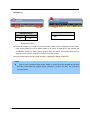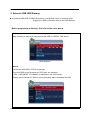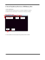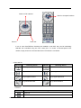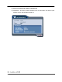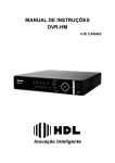
1
BDVR Series
DIGITAL VIDEO RECORDER
User Guide
BDVR-4 4 Channels
BDVR-8 8 Channels
BDVR-1616 Channels
User Guide
• Thank you for purchasing this Digital Video Recorder.
• Before using the Digital Video Recorder, please ensure that you read and
understand the User Guide.
• Please retain the User Guide for future reference.
• Before connecting and installing any third party cameras, monitors, alarms and
computers, please refer to the appropriate instruction manual for their correct
operation.
SAFETY PRECAUTIONS
CAUTION:
TO REDUCE THE RISK OF ELECTRIC SHOCK, DO NOT REMOVE COVER (OR BACK).
NO USER SERVICEABLE PARTS INSIDE. REFER SERVICING TO QUALIFIED
SERVICE PERSONNEL.
BDVR Manual
1
Version 1.2
The lightning flash with arrowhead symbol, within an equilateral
triangle, is intended to alert the user to the presence of un-insulated
“dangerous voltage” within the product’s enclosure that may be of
sufficient magnitude to constitute a risk of electric shock to persons.
The exclamation point within an equilateral triangle is intended to alert
the user to the presence of important operating and maintenance
(servicing) instructions in the literature accompanying the appliance.
WARNING:
TO PREVENT FIRE OR ELECTRIC SHOCK HAZARD,
DO NOT EXPOSE THIS APPLIANCE TO RAIN OR MOISTURE.
Contents
Disclaimer ............................................................................................... 5
Warning ................................................................................................... 5
Caution .................................................................................................... 7
Preventing Malfunctions ........................................................................ 7
Package Contents .................................................................................. 8
I.CONTROLS ........................................................................................... 9
1. Front Panel ...................................................................................................... 9
2. Rear Panel Connectors ................................................................................ 12
3. Remote Controller ........................................................................................ 13
4. Virtual Keypad for Mouse Control. ............................................................. 14
II. INSTALLATION & CONNECTIONS .................................................. 15
1. Camera, Monitor, Microphone, Alarm sensor and Power cord ................ 15
2. PC System Requirement for Network Connection..................................... 18
III.QUICK SETUP ................................................................................... 19
BDVR Manual
2
Version 1.2
1. TIME .............................................................................................................. 20
2. RECORD ....................................................................................................... 21
3. ADVANCED ................................................................................................... 22
IV.LIVE VIEWING ................................................................................... 23
1. Display Overview .......................................................................................... 23
2. Multi Screen Display and Sequencing ........................................................ 24
2.1 Full Screen Display .......................................................................................................24
2.2 Multi Screen Display and Sequencing Display. ..........................................................24
2.3 Repositioning.................................................................................................................25
3. Zooming ........................................................................................................ 25
4. Spot Monitor.................................................................................................. 26
V. OPERATION ...................................................................................... 27
1. Main Menu Overview .................................................................................... 27
2. Display Option .............................................................................................. 28
2.1. Display Setup ..................................................................................................................28
2.2. Sequential Setup (Auto Sequence) ...............................................................................29
3. Camera Setup ............................................................................................... 30
4. Motion Recording ......................................................................................... 32
5. Continuous Recording (Normal Recording) ............................................... 34
6. Alarm Recording ........................................................................................... 36
6.1. Record Setup ...................................................................................................................36
6.2. Alarm Setup .....................................................................................................................37
6.3. Recording Priority ...........................................................................................................38
7. Schedule Recording ..................................................................................... 40
8. Network Setup .............................................................................................. 43
8.1. IP Setup ............................................................................................................................43
8.2. E-Mail................................................................................................................................45
8.3 DDNS .................................................................................................................................46
8.4. MISC. ................................................................................................................................47
9. System Setup ................................................................................................ 48
9.1. General .............................................................................................................................48
9.2. Time ..................................................................................................................................49
9.3. Account ............................................................................................................................50
9.4. DISK..................................................................................................................................51
9.5. UPDATE ............................................................................................................................52
9.6. INFO..................................................................................................................................53
VI.PAN/TILT ZOOM CONTROL ............................................................. 54
BDVR Manual
3
Version 1.2
1. P.T.Z. Menu .................................................................................................... 54
2. Preset & Tour ................................................................................................ 55
3. Custom Functions ........................................................................................ 55
VII.SEARCH/ PLAYBACK ..................................................................... 58
1. Time Search .................................................................................................. 58
2. Log List Search/Alarm, Motion Search ....................................................... 59
VIII.BACKUP.......................................................................................... 60
1. USB Memory Stick Backup .......................................................................... 60
2. External USB HDD Backup .......................................................................... 61
3. External CD/DVD –RW Backup .................................................................... 64
4. How to Play Backup Data in USB Memory Stick Backup .......................... 65
5. Back up Range Setup ................................................................................... 66
Ⅸ.CLIENT PROGRAM .......................................................................... 67
1. DVR Player Program Introduction ............................................................... 68
1.1 Installation ........................................................................................................................68
1.2. How to Install ...................................................................................................................68
2. Features......................................................................................................... 70
2.1. CMS Overview .................................................................................................................70
2.2. Functions .........................................................................................................................71
3. DVR Control .................................................................................................. 81
3.1. Set List Manager .............................................................................................................82
3.2. Condition of DVR ............................................................................................................83
3.3. Indication of Camera ......................................................................................................84
3.4. Live Viewing ....................................................................................................................86
3.5. Context Menu ..................................................................................................................88
3.6. Playback...........................................................................................................................90
3.7. DVR Menu Setup .............................................................................................................94
4. Virtual DVR .................................................................................................... 95
4.1. What is Virtual DVR.........................................................................................................95
4.2. Virtual Set List Manager .................................................................................................95
4.3. Editing Virtual DVR .........................................................................................................97
4.4. Live Viewing on Virtual DVR ..........................................................................................98
Appendix 1: VIEW ONLY .................................................................................. 98
BDVR Manual
4
Version 1.2
Disclaimer
z The information in this manual is believed to be accurate and reliable as of the date of
publication. The information contained herein is subject to change without notice. Revisions or
New editions to this publication may be issued to incorporate such change
z We makes no warranties for damages resulting from corrupted or lost data due to a mistaken
operation or malfunction of the Digital Video Recorder, the software, the hard drives, personal
computers, peripheral devices, or unapproved/unsupported devices.
Warning
z Do not cover the ventilation opening or slots on the outer casing. To prevent the appliance
from overheating, provide at least two inches of air space around the vent and the slots.
z Do not drop metallic parts through slots. This could permanently damage the Digital Video
Recorder. Immediately turn the DVR’s power off or unplug the power cord from the power
BDVR Manual
5
Version 1.2
outlet. Contact a qualified service personnel authorised by your equipment distributor
z Do not attempt to disassemble or alter any part of the equipment that is not expressly
described in this guide. Disassembly or alteration may result in high voltage electrical shock.
Qualified service personnel authorised by your equipment distributor should conduct internal
inspections, alterations and repairs.
z Stop operating the equipment immediately if it emits smoke or noxious fumes. Failure to do
so may result in fire or electrical shock. Immediately turn the DVR’s power off, remove the
power cable from the power outlet. Confirm that smoke and fume emissions have ceased.
Please consult your DVR distributor.
z Stop operating the equipment if a heavy object is dropped or the casing is damaged. Do not
strike or shake. Failure to do so may result in fire or electrical shock. Immediately turn the
DVR’s power off or unplug the power cord from the power outlet. Please consult your DVR
distributor.
z Do not allow the equipment come into contact with, or become immersed in, water or other
liquids. Do not allow liquids to enter the interior. The DVR has not been waterproofed. If
the exterior comes into contact with liquids or salt air, wipe it dry with a soft, absorbent cloth.
In the event that the water or other foreign substances enter the interior, immediately turn the
DVR’s Power off or unplug the power cord from the power outlet. Continued use of the
equipment may result in fire or electrical shock. Please consult your DVR distributor.
z Do not use substances containing alcohol, benzene, thinners or other flammable substances
to clean or maintain the equipment. The use of these substances may lead to fire. Use a
dry cloth on a regular periodic basis and wipe away the dust and dirt that collects on the
device. In dusty, humid or greasy environments, the dust that collects around the ventilation
or the slots on the outer casing over long periods of time may become saturated with humidity
and short-circuit, leading to fire.
z Do not cut, damage, alter or place heavy items on the power cord. Any of these actions may
cause an electrical short circuit, which may lead to fire or electrical shock.
z Do not handle the device or power cord if your hands are wet. Handling it with wet hands
may lead to electrical shock.
When unplugging the cord, ensure that you hold the solid
portion of the plug. Pulling on the flexible portion of the cord may damage or expose the wire
and insulation, creating the potential for fires or electrical shocks.
z Use only the recommended power accessories. Use of power sources not expressly
recommended for this equipment may lead to overheating, distortion of the equipment, fire,
electrical shock or other hazards.
z Do not place the batteries near a heat source or expose them to direct flame or heat. Neither
should you immerse them in water. Such exposure may damage the batteries and lead to
BDVR Manual
6
Version 1.2
the leakage of corrosive liquids, fire, electrical shock, explosion or serious injury.
z Do not attempt to disassemble, alter or apply heat to the batteries. There is serious risk of
injury due to an explosion. Immediately flush with water any area of the body, including the
eyes and mouth, or clothing that comes into contact with the inner contents of the battery. If
the eyes or mouth contact these substances, immediately flush with water and seek medical
assistance from a medical professional.
z Avoid dropping or subjecting the batteries to severe impacts that could damage the casings.
It could lead to leakage and injury.
z Do not short-circuit the battery terminals with metallic objects, such as key holders. It could
lead to overheating, burns and other injuries.
z The supplied power supply and power cord are designed for exclusive use with the Digital
Video Recorder. Do not use it with other products or batteries. There is a risk of fire and
other hazards.
Caution
z Do not operate the appliance beyond its specified temperature, humidity or power source
ratings.
Do not use the appliance in an extreme environment where there is high
temperature or high humidity. Use the device at temperatures within +0°C - +40°C (32°F 104°F) and humidity below 90 %. The normal operating power source for this device is DC
12V 50/60Hz.
Preventing Malfunction
z Avoid Strong Magnetic Fields. Never place the DVR in close Proximity to electric motors or
other equipment generating strong electromagnetic fields. Exposures to strong magnetic fields
may cause malfunctions or corrupt image data.
z Avoid Condensation Related Problems. Moving the equipment rapidly between hot and cold
temperatures may cause condensation (water droplets) to form on its external and internal
surfaces. You can avoid this by placing the equipment in an airtight, resalable plastic bag and
BDVR Manual
7
Version 1.2
letting it adjust to temperature changes slowly before removing it from the bag.
z If Condensation forms inside the Digital Video Recorder. Stop using the equipment
immediately if you detect condensation. Continued use may damage the equipment. Remove
the power cord from the power outlet and wait until the moisture evaporates completely before
resuming use.
CAUTION
- Risk of Explosion if a battery is replaced with an incorrect type. Dispose of used batteries in
accordance with the instructions.
- The socket-outlet should be installed near the equipment and easily accessible
Package Contents
Please check the package and contents for visible damage. If any components are damaged or
missing, do not attempt to use the unit, contact the supplier immediately. If the unit must be
returned, it must be shipped in the original packing box.
CONTENTS
QUANTITY
DIGITAL VIDEO RECORDER
1 UNIT
CLIENT SOFTWARE CD
1
REMOTE CONTROLLER
1
BATTERY (COIN-CR2025)
1
AC ADAPTER
1
POWER CORD
1
USER GUIDE
1
BDVR Manual
8
REMARK
Version 1.2
I.CONTROLS
1. Front Panel
< 4 Channel >
< 8 Channel>
< 16 Channel>
1. Mode indicator : 3 LEDs display the status of the Digital Video Recorder.
Power (Blue), Recording (Red) and HDD (Green)
BDVR Manual
9
Version 1.2
2.
Playback / Record Control: These functions are used in Live mode or
Playback mode.
1) Direction buttons: In Menu setup mode, are used to move the cursor.
2)
[LOG / Playback Stop]
① Log : Press this button to access the log list.
② Stop : This button stops playback
3)
[R step or FR / REC ]
① Reverse Step : This button is used to move backwards, field by field, during STILL
mode
② Fast Rewind : This button is used to fast rewind during PLAYBACK mode.
③ REC : Press to start recording. Press the button again to stop.
4)
[Clear / Still or Playback] :
① Clear : This button is used to hide the On-Screen-Display information such as the
time, date and channel icons. This button removes alert icons on the corner of the
screen (AL, VL and PL).
This button is also used to turn off the alarm buzzer.
② Still or Playback: This button is used to still or 1 x playback during playback mode.
5)
[Schedule / F step or FF] :
① Schedule : Press this button to make scheduled recording standby. Press the button
again to stop.
② Forward step : This button is used to move forward field by field (picture by picture)
during STILL mode
③ F.F. : This button is used to Fast Forward during PLAYBACK mode.
3. Menu / ESC Button :
① Menu : Press this button to display the MAIN MENU screen.
② ESC : Press this button to exit a menu without saving.
4. . Enter :
: Press this button to save menu settings
BDVR Manual
10
Version 1.2
5. . QUAD
: Press this button to display the cameras in multi-screen view.
6. . Channel / Numeric Buttons :
Press the buttons to enter data or make selections. Press “–” or “+” to enter appropriate
numbers when prompted for a password, or appropriate dates in schedule option mode.
[-, +] : To decrease settings, To increase settings
7. Remote control signal receiver :
Do not block the receiver port on the unit. Doing so may cause the remote controller to
function improperly.
8. POWER button:
Press this button to turn the power on; press again to turn the power off. The POWER LED
indicator is lit when the power is on.
9. USB Port: USB port allows light backups of video files to devices.
BDVR Manual
11
Version 1.2
2. Rear Panel Connectors
1)
CAM1~4 or 1~8: BNC input (Camera 1~4 or 1~8) connectors
2)
MONITOR (Composite Output) : BNC standard composite video output connector.
3)
SPOT : Spot Out connector
4)
AUDIO Input / SPEAKER (Output) connectors : RCA
5)
VGA Out connector
6)
LAN (RJ-45 Ethernet Port) : For connecting to remote PC via Ethernet network.
7)
MOUSE connection : Connect PS2 USB mouse to this port. To use USB only mouse,
connect it to USB port at rear panel.
8)
SENSOR (ALARM IN 1~4 or 1~8) : For connecting alarm inputs.
9)
RELAY (ALARM OUT 1) : For connecting alarm out relays.
10) RS-422 : For connecting to PTZ camera.
11) RS-232C : Development purposes only.
12) POWER : DC power Jack
13) FIELD GND : Ground
BDVR Manual
12
Version 1.2
3. Remote Controller
BDVR Manual
13
Version 1.2
4. Virtual Keypad for Mouse Control.
This DVR can be controlled by Mouse. Connect a mouse via USB port before use. Right
clicking on the mouse in Live mode and Playback mode, displays the following Virtual
Remote Controller and Virtual Keypad and can be used to enter PASSWORD and Camera
Name etc
Repositioning
TIME SEARCH
LOG
SPOT OUT
BACK UP
INFORMATION
PAN/TILT/ZOOM
DISPLAY MODE
CANCEL / OSD OFF
ZOOM
ENTER
MENU
- BUTTON
+ BUTTON
REWIND
FAST FORWARD
STOP
SCHEDULE REC
PLAY
ON/OFF
RECORD
STEP
NUMBERS & ALPHABET
[LIVE]
[PLAYBACK]
[Virtual Keypad]
BDVR Manual
14
Version 1.2
II. INSTALLATION & CONNECTIONS
1. Camera, Monitor, Microphone, Alarm Sensor and Power Cord
1-1. System Configuration Diagram
The following illustration is showing a fully installed system.
BDVR Manual
15
Version 1.2
1-2. CAMERA
This product can be installed for 4~16 cameras, dependant on Model number.
Connect cameras to the VIDEO IN (BNC) on the back panel of the machine.
To connect a PTZ camera, connect the PTZ camera’s control line to the RS-422 TX+,
RS-422 TX- terminal and connect the video output to one out of VIDEO IN on the back panel
of the product.
PTZ CAMERA
BDVR Manual
16
Version 1.2
1.3 AUDIO
The system has one channel audio input and output. To record and playback audio signals,
connect an audio device (microphone) to the AUDIO IN (1 Vp-p @600 ohms) and speaker to
the AUDIO OUTPUT (see illustration below).
1.4 MONITOR
There are three video outputs (2 x BNC, 1 x VGA) on the rear panel of the system.
Connect monitors depending on your application.
1 x BNC for Main composite video output.
1 x BNC for Spot composite video output.
1 x VGA output.
BDVR Manual
17
Version 1.2
2. PC System Requirement for Network Connection.
(a) Pentium-4 2.0GHz or higher
(b) 256MB System Memory
(c) 1,024 x 768 Display Resolution, 32 Bit colour
(d) Windows XP, VISTA
(e) Spare 10/100-BaseT Ethernet Port
(f) Microsoft DirectX 9.0c
It is recommended to have DirectX 9.0c loaded on the Client PC. DirectX 9.0c is available for
download from Microsoft homepage
(www.microsoft.com/windows/directx).
<Disclaimer>
The remote viewing on a network connection may not work on all personal computers
due to differences in personal settings and hardware configurations.
BDVR Manual
18
Version 1.2
III.QUICK SETUP
To switch on the DVR, press the [POWER] button on the front panel or on the remote
controller. When the Digital Video Recorder is powered on, the Live Viewing screenl appears
after about 30 seconds.
1) First, stop recording to enter and set the QUICK SETUP menu. While the DVR is
recording, TIME and RECORD menus are not activated.
2) When prompted for a password, enter the password using the Numeric buttons.
3) The Factory Default password for the unit is “000000”
4) Press the [MENU] button to display the QUICK SETUP screen.
5) QUICK SETUP menu appears once a password is entered.
6) Use Directional buttons to select Menu and press the [ENTER] button to confirm.
BDVR Manual
19
Version 1.2
1. TIME
When the Digital Video Recorder is powered on, for the very first time, it is important to set
the exact date and time.
1) Select the “Time” menu tab using the directional buttons.
2) Enter the Date and Time by pressing the numeric buttons on the remote controller
or “–/+” on the unit.
3) Press the [ENTER] button to exit a menu and save the changes. Press the [ESC] to
exit a menu without making changes.
Note:
1. Recording mode
While recording mode you cannot set the time. Stop recording to change the TIME.
2. Live mode after time set up
After the time is set up, press the Record button to continue recording.
BDVR Manual
20
Version 1.2
2. RECORD
There is an easy setup for recording.
2-1. RECORD MODE
1) Select the “RECORD” menu tab using the directional buttons.
2) Select MODE by pressing the “–/+” buttons on the remote controller or the unit.
3) Press the [ENTER] button to exit a menu and save the changes. Press the [ESC] to
exit a menu without making changes.
• CIF, 4/8Ch:
Each channel records at CIF resolution: 360x240 (360x288).
RECORD
• Field, 4/8Ch : Each channel records at Field resolution: 720x240 (720x288).
MODE
• Frame, 4/8Ch : Each channel records at Frame resolution: 720x480 (720x576)
•Frame + CIF:
Channel number 1 - 720x480 (720x576)+Channel number 2~8 - : 360x240 (360x280)
2.2. RECORD DAYS
1) Select RECORDING DAYS using the “–/+” buttons on the remote controller or the unit.
2) Press the [ENTER] button to exit a menu and save the changes. Press the [ESC] to
exit a menu without making changes.
2.3. PRIORITY
1) Select “RATE” or “QAULITY using the “–/+” buttons on the remote controller or the
unit.
2) “RATE” : DVR is automatically set up with a high recording speed mode.
3) “QUALITY” : DVR is automatically set up with a high picture quality mode.
BDVR Manual
21
Version 1.2
2.4 RECORD SETUP INFO
This displays the picture quality and recording speed.
1.
Note:
START RECORDING
: When setup is finished, press the [REC] button on the front panel or the
remote controller to start recording,
2. To set up individual recording for each channel, or a more specified
setup, enter into RECORD on the main menu.
Please refer to 3. ADVANCED on how to enter into the main menu.
3. ADVANCED
Select “ON” or “OFF” using the “–/+” buttons on the remote controller or the unit.
1) “ON” : Select this to enter into the main menu and press the [ENTER] button to exit a
menu and save the changes.
z
Escape from “QUICK SETUP” menu by pressing “ESC” button.*
z
Press the MENU button again to enter into MAIN MENU.
2) “OFF” : Select this to stay in the “QUICK SETUP” menu.
3) To return to the Quick SETUP menu from Main Menu, refer to 2-1 DISPLAY SETUP
part of this manual
BDVR Manual
22
Version 1.2
IV.LIVE VIEWING
1. Display Overview
Recording Mode
Event Indicator
Camera No and Title
Status
1.
(1) Indicates an Alarm has been triggered by an alarm sensor. To cancel, press the
[CANCEL/ESC] button on the remote controller or the [CLR] button the front panel.
(2) Indicates Motion detected. To cancel, press the [CANCEL/ESC] button on remote the
controller or the [CLR] button the front panel.
(3) Indicates Video Loss during Recording. To cancel, press the [CANCEL/ESC] button on
the remote controller or the [CLR] button on the front panel.
(1) (2) (3) (4) (5)
2.
(1) Indicates an USB Device is connected on Front panel. It changes to a blue colour
while doing a backup. If a Mouse is connected cursor appears.
(2) Indicates the DVR is now recording.
(3) Indicates Schedule Record mode is on. It changes to a blue colour when Schedule
Record starts.
(4) Indicates Audio is stored during the selected playback and turns to a blue colour.
(5) Shows the Number of Client, which are connected to the Network (MAX:3).
3.
4.
: Displays Year, Month, Day, Time and Date.
: Shows the remaining recording time of the DVR. If the remaining HDD
capacity is less than 4GB, the blue “Recycling” icon is shown.
BDVR Manual
23
Version 1.2
2. Multi Screen Display and Sequencing
2.1 Full Screen Display
Select any camera for Full Screen display by pressing the Number button of the
associated camera.
2.2 Multi Screen Display and Sequencing Display.
Press the [DISPLAY] button to activate the multi-screen display. It changes in order,
as shown below, from the SPLIT MODE choices. When in a 16-way screen display,
press the [DISPLAY] button for 1 second to begin full screen sequencing. The
sequence mode and dwell times are programmable. For detailed information about
configuring these, see “Sequence Setup”.
If the sequence mode is not activated, it
moves to Quad mode instead of Sequencing.
BDVR Manual
24
Version 1.2
2.3 Repositioning
To reposition a camera view on screen.
2.3.1.
Virtual Remote Controller
① Press the
button on the Virtual Remote Controller, using the mouse, and the
icon is displayed on the screen. Move the
icon to the desired position by pressing the
directional buttons on the remote controller or Virtual Control Pad.
② Press a Numeric button to reposition the selected camera. Press the [Enter] button to exit here and
save the changes.
2.3.2.
Mouse
Drag the selected camera to the new position using the mouse.
3. Zooming
BDVR Manual
25
Version 1.2
During Live View mode or Playback, it is possible to zoom into a section of the screen to get
a close-up view of the image.
1. To activate the digital zoom, select the full screen display of the camera you wish to
zoom.
2. Then press the [ZOOM] button on the IR Remote controller.
A Zoom area box pops
up, as shown below.
x2
x4
] buttons.
3. Move the box to the desired position using the directional [
4. Press the [+] button to enlarge the image and the [ - ] button to zoom out the image.
5. Press the [CANCEL] button to return normal mode.
Note:
If the Zoom button is pressed while in a multi-screen display, the zoom operation is not
activated. It MUST be a full screen display.
4. Spot Monitor
In addition to the Main Monitor, attaching a Spot Monitor enables a user to monitor specific
channels independently from the main monitor.
y Press the [Spot] button on the remote controller, then press the number button you wish
watch as full screen.
y Press the [Spot] button twice to auto switch cameras. The Sequence interval can be set in
the Sequential Setup.
y When an alarm has been triggered, that specific channel goes into Full Screen.
BDVR Manual
26
Version 1.2
V. OPERATION
1. Main Menu Overview
When the DVR is powered on, a Live Viewing screen appears after an initialisation period of
about 30 seconds. Press the [MENU] button to access the main menu.
An Admin
Password Box appears. Enter the password using the Numeric buttons on the IR Remote
Control or CH increase button on the Front Panel. Default password is ‘000000’. Main Menu
is displayed only after a correct password is entered, shown below.
Note: Factory default Admin/User password is 000000. It is recommended that the
“PASSWORD” is changed when the DVR is installed. Refer to [System Setup].
1. Use the directional buttons
[
]
to select the desired menu. Items selected in the
menu are highlighted.
2. Press the [ENTER] button to select the menu and display Sub-Menus. Use the Left/ Right buttons
[
] to select tabs on menus. Selected items change to an [ORANGE] colour.
Selected
Not selected
* It is automatically saves changes when you move between menu tabs.
3.
Press the [ENTER] button to exit a menu and save the changes.
Press the [CANCEL] to exit a menu without changes.
BDVR Manual
27
Version 1.2
2. Display Option
2.1. Display Setup
1. Use the directional buttons [
] to select “DISPLAY” menu. Then, press the
[ENTER] button to display “DISPLAY SETUP”.
2. Use the Left/Right buttons [
] to select a menu tab (
).
Selected items change to an [ORANGE] colour.
3. Use the Down [T] button to specify an option.
4. Use the [-, +] buttons to change values
ITEM
ADJUSTMENT
y Select “Show” or “Hide” below the status bar on the Main Monitor.
STATUS BAR
CAMERA
BORDER LINE
BACKGROUND
SPLIT MODE
QUICK SETUP
y Select On-Screen-Display information for Camera Number and Title.
y Select Border Line between cameras.
[WHITE Æ GREY Æ DARK GREY Æ BLACK]
y Select Background colour when there is NO VIDEO input.
[GREY Æ DARK GREY Æ BLACK Æ BLUE Æ WHITE]
y Display is changed according to the order, as shown, from the choices of
SPLIT MODE.
ySelect “ON” to resume “Quick SETUP” menu and “OFF” to stay in main
menu setup.
5. Save changes and exit the menu, press the [ENTER] button.
Exit the menu without making changes, press the [CANCEL] button.
BDVR Manual
28
Version 1.2
2.2. Sequential Setup (Auto Sequence)
ITEM
DWELL TIME
SEQ. MODE
FULL SCREEN
BDVR Manual
DEFAULT
ADJUSTMENT
2 Sec
y Specify the dwell time of each camera or Multi-screen display.
Use the [-, +] button : [1 second ~ 30 second]
None
y Select desired sequence mode for switching.
ALL
y Select the cameras to be included or excluded from the
automatic sequencing.
29
Version 1.2
3. Camera Setup
1. Use the directional buttons [
] to select “CAMERA” menu. Then, press the [ENTER]
button to display “CAMERA”.
2. Use the Left/Right buttons [
] or Number button to select the Camera you wish to configure.
3. Use the Down [T] button to move to the specified options and use the Left/Right
buttons [WX] to select other items.
4. Use the [-, +] buttons to change values.
ITEM
DEFAULT
ADJUSTMENT
No
y If the Covert Mode is “YES” the selected camera is invisible
COVERT
from all live displays, playback and Network but continues to
record. Covert cameras are viewable after changing to “NO”.
BRIGHTNESS
CONTRAST
COLOUR
50%
y The brightness of each camera can be adjusted by pressing the
[-,+] buttons.
50%
y The contrast of each camera is adjustable by pressing the [-,+]
buttons.
50%
y The colour of each camera is adjustable by pressing the [-,+]
buttons.
Camera #
TITLE
y A combination of 12 alphanumerics can be entered to label each
camera. Press the appropriate Numeric button to type in a
camera title. See the table on the next page.
P/T/Z MODEL
P/T/Z ID
None
Camera No
y Select P/TZ camera model to control.
y Select appropriate channel for the PTZ camera. Camera ID
means Camera address.
5. Save changes and exit the menu, press the [ENTER] button.
Exit the menu without making changes, press the [CANCEL] button.
BDVR Manual
30
Version 1.2
1st
2nd
3rd
4th
Press
Press
Press
Press
1
A
B
C
1
2
D
E
F
3
G
H
4
J
5
6
No
1st
2nd
3rd
4th
Press
Press
Press
Press
7
S
T
U
7
2
8
V
W
X
8
I
3
9
Y
Z
@
9
K
L
4
0
.
-
_
0
M
N
O
5
10+
SPACE
P
Q
R
6
No
<Insert characters from IR Remote Controller >
BDVR Manual
31
Version 1.2
4. Motion Recording
1. Use the directional buttons [
] to select “MOTION” menu. Then, press the [ENTER]
button to display “MOTION”.
2. Use the Left/Right buttons [
3. Use the Down [
] or Number button to select the Camera you wish to configure.
] button to move specified menu and use the Left/Right buttons [
] to select
other items.
4. Use the [-, +] buttons to change values.
ITEM
RECORD TIME
CAMERA
ADJUSTMENT
y Determines the recording duration when motion is detected.
[10SEC ~ 300SEC]
y Use the Left/Right buttons [
] or Number button to select the Camera you
SELECTION
wish to configure.
SENSITIVITY
y Level 1: Low sensitivity~ Level 20: High sensitivity.
y Use this menu to setup zones for Motion Detection The screen shown below
will overlay over the current video image.
y Motion zones are set to OFF – and covered by a GREY mask.
MOTION GRID
y It is divided into 16 Grid and selectable by the Number button on IR Remote.
BDVR Manual
y
: Select All.
y :
: Cover All.
32
Version 1.2
y Motion detected zones are changed to a BLUE Colour.
Motion Detected zones
y Use the Numeric button to select Motion Grid. GREY mask is cleared, or use
<+> button to select Motion Grid on the Front Panel. A Running Man Icon
is
activated. The <+> button is used for selecting and canceling. Use the <-> button
to escape from the Grid Menu.
y It is also possible to select smaller motion grids for more precise motion
detection using the CMS.
5. Save changes and exit the menu, press [ENTER] button. Then go “RECORD” Menu.
6. Select “ON” or “OFF” to Enable or Disable motion detection, on a per camera basis,
as shown below.
7. Press the REC button, and Recording starts according to configured Recording Quality
and Frame Rate when Motion is detected. It reverts back to stand-by mode after
motion recording time ends. Camera does not record under normal conditions.
Note: Motion Duration is extended if another motion is detected while in motion
recording.
Note: There may be cases when the recorder’s built-in motion detection function does
not operate properly due to the condition of the input video signal, or other factors.
Note: It is recommended that at least 3 motion blocks are selected to get more accurate
motion recording.
BDVR Manual
33
Version 1.2
5. Continuous Recording (Normal Recording)
The DVR comes with certain preset settings from the factory. Therefore, once the DVR
is installed immediate recording is possible by pressing the record button. By default,
audio alarm and motion recording are set to OFF.
1. Use the directional buttons [
] to select “RECORD” menu. Then, press the [ENTER]
button to display “RECORD”.
2. Use the directional buttons [
] to select the Camera you wish to configure.
3. Use the [-, +] buttons to change values.
ITEM
USE
QUALITY
ADJUSTMENT
y Enable or Disable Recording on each camera.
y Specify the record picture quality for each camera.
ULTRA Æ SUPER Æ HIGH Æ MIDDLE ÆLOW
y Select the recording speed for each camera.
RATE
: Recording resolutions change between Frame, Field and CIF.
<Refer to System >
ySelect Audio recording: ON or OFF.
AUDIO
The audio data is always recorded in real time unlike the video data which could be
recorded in various modes, including real time. There may be a slight delay in
synchronisation of the audio to video data.
MOTION
ySelect Motion Recording ON or OFF. Camera does not record under normal
conditions. See the Motion Recording section.
Note: Press the [MENU] button on the first line of each item to apply the setting for the remaining
channels.
BDVR Manual
34
Version 1.2
5. Save changes and exit the menu, press the [ENTER] button.
6. Pressing the [REC] button lights the front panel red REC LED, and recording starts.
7. To stop Recording, press the “STOP” button on the IR remote, or the [REC] button again
on the Front Panel.
< Approximate File Size>
Quality
NTSC
PAL
720x480
720x240
360x240
720x576
720x288
360x288
UNIT
LOW
5.1
3.2
2.0
6.1
3.8
2.4
KB
MIDDLE
7.2
4.5
2.8
8.6
5.4
3.4
KB
HIGH
10.2
6.4
4
12.3
7.7
4.8
KB
SUPER
15.4
9.6
6
18.4
11.5
7.2
KB
ULTRA
24.6
15.4
9.6
29.5
18.4
11.5
KB
* The table is a theoretical calculation because other unknown conditions can affect file
size, such as, the condition of the video signal and image noise.
BDVR Manual
35
Version 1.2
6. Alarm Recording
Always verify the Alarm Record settings prior to starting alarm recording. Please note that
alarm recording is independent of any recording modes. Alarm Record starts after Alarm
Record Enable.
6.1. Record Setup
1. Use the directional buttons [STWX] to select the “ALARM” menu. Then, press the
[ENTER] button to display “Alarm Record Setup”.
2. Use the Left/Right buttons [WX] to select a menu tab (
).
3. Use the directional buttons [STWX] to select the Camera you wish to configure.
4. Use the [-, +] buttons to change values.
ITEM
USE
QUALITY
ADJUSTMENT
y Enable or Disable Alarm Recording, on a per camera basis.
y Specify the record picture quality for each camera on Alarm Recording.
ULTRA Æ SUPER Æ HIGH Æ MIDDLE Æ LOW
RATE
y Select the recording rate of each camera when an Alarm is triggered
AUDIO
y Select Audio recording: ON or OFF.
INPUT
y Specify the type of Alarm Input device.
Note: Press the [MENU] button on the first line of each item to apply the setting for the remaining
channels.
5. Save changes and exit the menu, press the [ENTER] button.
Exit the menu without making changes, press the [CANCEL] button.
BDVR Manual
36
Version 1.2
6.2. Alarm Setup
ITEM
RECORD TIME
ADJUSTMENT
y Determines the duration of recording after the alarm signal has been
activated. [10SEC ~ 300SEC]
y ALL: Start to record All Alarm “ON” channels if any Alarm signal is
RECORD CAMERA
triggered.
y 1:1: Start to record the Channel on which the Alarm is triggered.
y ON: The Buzzer sounds if an alarm is triggered. The Buzzer sounds for the
duration of the RECORD TIME. This buzzer relates to Alarm Out.
Configure Alarm Out as “ON” for the Alarm Buzzer.
ALARM BUZZER
yOFF: Disables the ALARM BUZZER function.
Note: Press the [-] button to stop the buzzer immediately. Stopping the
buzzer does not stop the alarm recording.
y Configure which relay is triggered when an alarm is activated, per camera.
Select from four available options:
Video Loss, Motion, Alarm ALL, Each Alarm, System.
ALARM OUT1
Note: If “System” is selected, the relay is triggered when the System
has problems such as HDD FAIL, Power Loss etc.
y Press the [Cancel] button to stop Alarm Out.
It is cleared in order: Alarm>Motion> Video Loss
6. Save changes and exit the menu, press the [ENTER] button.
7. Pressing the [REC] button, after setting RECORD ENABLE, lights the red REC LED on
the front panel and recording starts.
BDVR Manual
37
Version 1.2
6.3. Recording Priority
<Example 1>
ALARM RECORDING STATUS
RECORDING STATUS
USE
MOTION
OFF
ON
OFF
Resulting Actions:
z
Press the REC button to commence Alarm Recording, based on the configuration shown above.
(Recording Quality (Super), Frame Rate (6F/S) and Audio).
The system reverts back to stand by mode once alarm recording finishes.
The DVR system starts recording only when an alarm is activated.
<Example 2>
ALARM RECORDING STATUS
RECORDING STATUS
USE
MOTION
ON
z
ON
OFF
Resulting Actions:
Press the REC button to commence continuous recording, based on the configuration shown
above (High picture quality at 3F/S without Audio).
If an alarm is triggered on this channel, the configuration changes to Super picture quality
at 6F/S with Audio. The system reverts back to continuous recording once alarm recording
finishes. Alarm Recording takes priority.
BDVR Manual
38
Version 1.2
<Example 3>
ALARM RECORDING STATUS
RECORDING STATUS
USE
MOTION
ON
ON
ON
z Resulting Actions:
Press the REC button to commence motion recording, based on the configuration shown above
(High picture quality at 15 F/S without audio). If an Alarm is triggered on this channel, the
configuration changes to Super picture quality at 6F/S with Audio. The system reverts back to
stand-by mode for Alarm or Motion once alarm recording finishes.
The DVR system starts recording when an Alarm is triggered or Motion is detected.
Note:
z
If two or more recording modes (Alarm, Motion or Continuous) are operational, the alarm
recording mode takes the highest priority followed by motion and then the continuous
recording mode.
BDVR Manual
39
Version 1.2
7. Schedule Recording
The schedule chart shows a graphical representation of the defined record mode: Mode1~4.
However, the schedules are only displayed if a corresponding schedule has been
configured in the schedule menu.
1. Use the directional buttons [STWX] to select “SCHEDULE” menu. Then, press the
[ENTER] button to display “Schedule Chart”.
2. Use
(
the
Left/Right
buttons
[WX]
to
select
a
menu
tab
).
3. Use the Down button [T] to select the Day to be configured.
The schedule breaks down the days of the week into eight different categories: ALL,
SUN, MON, TUE, WED, THU, FRI and SAT. ALL is for everyday of the week. A
Daily schedule has priority over ALL.
4. Press the [Enter] button on one of the eight categories. A detailed menu pops up
for the selected Day, as shown below.
BDVR Manual
40
Version 1.2
5. Enter the beginning and end time, then select the Record mode for recording.
(1) BEGIN: The time to start recording.
(2) END: The time to end recording. The end time must not be before the starting
time or the same as the start time.
(3) MODE: Up to 4 different recording modes can be pre-determined for schedule
recording (MODE1 ~ MODE4).
6. Define modes.
* Refer to Basic Recording for set up
Note:
y The recording time uses a 24 Hour clock (00:00 - 23:59). You need to set 2 days if the setting
goes over one day.
D/W
BEGIN
END
MODE
Monday
18:00
23:59
MODE 1
Tuesday
00:00
08:59
MODE 1
y The recording does not start when End time is ahead of Start time.
EXAMPLE
D/W
Monday
BEGIN
END
MODE
18:00
08:59
MODE 1
7. To activate Schedule Recording after configuration, press the SCHEDULE button.
The SCHEDULE indicator illuminates. When a program is within the current time,
the REC indicator illuminates and the unit begins recording. Please note that if there
are no schedules configured the DVR does not record.
8. When the scheduled recording period is over, the REC indicator goes off and
recording stops.
9. If you wish to stop recording while Schedule Recording, press the SCHEDULE
button. The SCHEDULE indicator goes out and the Schedule Recording Mode is
released.
BDVR Manual
41
Version 1.2
Summary of Combinations
RECORD
ALARM
SCHEDULE
RECORD MODE
MENU
CAMERA
MOTION
USE
Normal
MODE 1~4
Continuous
RECORD
ON
OFF
OFF
OFF
OFF
Motion
RECORD
ON
ON
OFF
OFF
OFF
Alarm
ALARM
OFF
OFF
ON
ON
OFF
Schedule
SCHEDULE
OFF
OFF
OFF
OFF
ON
Schedule Motion
SCHEDULE
OFF
ON
OFF
OFF
ON
Normal and Alarm
RECORD &ALARM
ON
OFF
ON
ON
OFF
Motion and Alarm
RECORD &ALARM
ON
ON
ON
ON
OFF
Schedule and
ALARM &SCHEDULE
OFF
OFF
ON
OFF
ON
BDVR Manual
42
Version 1.2
8. Network Setup
A static service has an IP address that remains constant for the duration of the contract
with the Internet Service Provider (ISP), whereas a dynamic service consists of an IP
address that possibly changes every time a new connection is made through the ISP, or
recurrently in a given period of time. Most Internet Service Providers offer both solutions and
this manual distinguishes between them, according to commonly available service types,
when configuring the DVR for networking purposes.
8.1. IP setup
1.
Use the directional buttons [
] to select “NETWORK” menu. Then, press the [ENTER]
button to display “Network”.
2.
3.
Use the Down button [ ] to specify the connection details.
Use the [-, +] buttons to change values.
4.
Save changes and exit the menu, press the [ENTER] button.
Exit the menu without making changes, press the [CANCEL] button.
ITEM
ADJUSTMENT
y STATIC IP: Edit IP address, Gateway and Network Subnet Mask.
y DHCP: Dynamic Host Configuration Protocol.
CONFIG
It is set automatically from DHCP if there is a Local DHCP server (i.e. Local
Router). If DHCP is set to ON, the IP address, Gateway and Subnet Mask
are assigned by the DHCP Server (i.e. the Local Area Network Router).
IP Address
y Enter the Static IP address
Netmask
y Enter the address of the Subnet Mask.
Gateway
y Enter the IP address for the internet Gateway Server.
DNS Server
PORT
BDVR Manual
y Verify the address of the domain name system (DNS) Server
y Select “0000 ~ 9999”
43
Version 1.2
The DVR’s connection port can be changed in case the default port, 7000,
cannot be opened. The DVR’s service port may be modified to allow the
CMS connection.
Note: How to connect the DVR via a Network using DDNS
1. Select DHCP.
Dynamic IP
Router
DVR
DVR
2. Please check “Serial No” on System Menu.
3. Enter DNS name<ex: 0Hhttp://L10020E.dvrhost.com:7000> on Web browser or CMS.
BDVR Manual
44
Version 1.2
8.2. E-Mail
The DVR is capable of sending e-mails, when an event occurs, to up to 5 different e-mail
accounts: Events are Alarm , Video Loss, Power Loss (when power recovers), HDD Failure.
There are two methods of sending an e-mail; Using “Unique” or “Public/ your own mail
server”.
ACTION
ITEM
OFF
USE
Default
SMTP
Server
SMTP
y Select the manufacturers default mail server.
: You do not need to setup SMTP server.
y Select a SMTP mail server and then setup the SMTP menu below.
y Select Highlight SMTP Server and then press numeric buttons to define
an e-mail server.
PORT
y Define the port that the SMTP server will communicate through.
AUTH
y Select Authentication: on or off. The default is off.
USER ID
Password
E-mail Address
BDVR Manual
y Select the e-mail notification state: on or off. The default is off.
y Enter the user ID of the Mail Server if your server needs Authentication.
(It’s recognised as lower case letters, even if displayed as capital letters)
y Enter the password, if your server needs Authentication.
(It only recognises lower case, we do not support capital letters)
y Enter an e-mail address to send the notifications to.
45
Version 1.2
8.3 DDNS
ON
ITEM
ACTION
y OFF : NO use of DDNS
y DEFAULT : use default “dvrhost.com” server for DDNS.
USE
If the DVR’s host name (SYSTEM >INFO) is L50AD25, Your DVR’s DDNS
address is http://L50AD25.dvrhost.com:portNO
y DYNDNS : to use “Dyndns.com” domain.
Domain Name
y Enter your domain name if you use “Dyndns” server for DDNS.
User ID
y Enter user ID for DDNS.
Password
y Enter user PW for DDNS
DDNS Test
y Test your DDNS address.
BDVR Manual
46
Version 1.2
8.4. MISC.
ITEM
BANDWIDTH
BDVR Manual
ADJUSTMENT
y “Unlimited” is set by default. Select between “64 KBPS ~ 8 MBPS”
47
Version 1.2
9. System Setup
9.1. General
1. Use the directional buttons [STWX] to select “SYSTEM” menu. Then, press [ENTER] button.
2. Use the Left/Right buttons [WX] to select menu tabs.
3. Use the Down button [T] to specify the detail.
4. Use the [-, +] buttons to change values.
5. Save changes and exit the menu, press the [ENTER] button.
Exit the menu without making changes, press the [CANCEL] button.
ITEM
ACTION
yThe DVR locks all the buttons after three minutes of inactivity, like a
AUTO LOCK
Screensaver. The buttons can be unlocked with the user password. Default is
“OFF”.
KEY TONE
y By default, the DVR emits a beep every time a button is pressed. Set the key
tone to OFF to turn button beep off. Default is “ON”
yCIF, 4/8Ch: Default setting
The system records each camera individually and then multiplexes them.
Each channel records at CIF resolution: 360x288.
• Field, 4/8Ch: The system records each camera individually and then multiplexes them.
RECORD MODE
Each channel records at Field resolution: 720x288.
• Frame, 4/8Ch: The system records each camera individually and then multiplexes
them. Each channel records at Frame resolution: 720x576
• Frame + CIF :
Channel number 1 - 720x576 + Channel number 2~8 - : 360x280
PB DEINTERLACE
RUN ON BOOT
BDVR Manual
y ON: Reduces image flickering but also reduces picture quality.
y OFF: Better picture quality for still images but may flicker for moving pictures.
y It’s purpose is to start REC, without pressing the REC button, when switched on.
48
Version 1.2
PASSWORD
FACTORY
DEFAULT
y If you choose “OFF”, the password window is not shown except for POWER/
SERVICE MENU/ RECORDING STOP/ SCHEDULE RECORDING STOP.
• To restore factory default settings Stop recording and then select “START” using the
ENTER button.
KEY SENSITIVITY
• The sensitivity of the front panel touch buttons can be controlled with this setting.
y To select the DVR to be controlled with the remote controller, press and hold the DVR
ID button. While holding the DVR ID button, press the appropriate DVR ID number.
SYSTEM ID
For example, enter 05 for DVR ID 05, enter 43 for DVR ID 43 etc..
y Set the IR controller ID to “00” to control all DVR’s at the same time; whatever DVR
ID they are.
9.2. Time
ITEM
ADJUSTMENT
DATE & TIME
y Enter the Date and Time.
Note:
When in Recording mode the time cannot be setup. Stop recording to change the
TIME/DATE.
< Record Mode>
BDVR Manual
< Live Mode after time setup >
49
Version 1.2
9.3. Account
Admin can define each User’s Authority. Select a User (1~5), then select the Activate option:
on or off. When enabled, it’s possible to configure individual User settings: Monitoring,
Playback, Back up, Network, Configuration (Main Menu Setup), Shutdown (Power off).
Enter the 6 numbers for the new password, and then re-enter the same password under
COMFIRM section.
BDVR Manual
The asterisks advance automatically as the numbers are entered.
50
Version 1.2
9.4. DISK
ITEM
ACTION
1. Stop the DVR completely before a disk format.
2. Use the [-, +] button to change select device.
* Internal HDD
* USB – Memory Stick
* USB – CD/DVD-RW
* USB – HDD
Note:
FORMAT
When you format USB-HDD, it is formatted to a FAT 32 format type.
3. Use the Down button [T] to move
, then press [“+” or “ –“]
button to start formatting.
4. Formatting will begin, and the progress is displayed at the bottom of the
window. Please note that it takes 10~30 seconds to format a HDD.
5. When formatting is finished, it will display COMPLETE, and also SUCCESS at
the bottom of the window.
Users can select the recording policy of the system’s internal hard disk drive. By
default, the system’s hard disk drive is set to overwrite from the beginning when it
OVERWRITE
becomes full.
yON: By default, the hard disk drive will overwrite from the beginning when it
becomes full.
yOFF: It stops recording when the HDD is full.
DISK MONITOR
y It stops automatically if a HDD failure happens. It starts “Monitoring” again after
DVR reboot (use the [-, +] buttons to stop or start).
Allows you to configure when the DVR automatically deletes all data from the HDD. It
RECORD LIMIT
leaves the data for a set duration from the current time.
[NONE Æ 12HOURS Æ 1DAY~ 6DAYS Æ 1WEEK ~ 4WEEKS]
BDVR Manual
51
Version 1.2
9.5. UPDATE.
1) Download the latest firmware file and copy to a USB Flash memory stick in the Root Folder.
2) Turn on your DVR (if in use, please stop recording)
3) Plug USB memory stick into the front USB port and check if USB icon shows up on the Status bar.
4) Move to upgrade menu and start the upgrade by pressing [+]/[enter] button.
5) Wait until upgrade finishes and the “Success” message is shown, then Press [+] to restart.
Indicator
CONDITION
H/W VERSION
y Shows the Main PCB version of the system.
S/W VERSION
y Shows the Software version of the system.
Note:
While in recording mode, you cannot update DVR. Stop recording to update.
< Record Mode>
NOTE:
1. Make sure the USB Flash memory stick has enough space for update file size.
2. Do not make a special folder in the memory stick for these files.
3. Do not format the USB, just remove all files inside.
4. Do not switch OFF or PRESS any key during the upgrade process.
5. Please consult with your installer or dealer before upgrading the DVR.
BDVR Manual
52
Version 1.2
9.6. INFO
Press the Info button on the IR remote to display system information. Other menus are
blocked. This menu provides general information, as listed below:
Indicator
MODEL
DISPLAY
y Display the number of channels and compression.
HOSTNAME.
y Display Hostname and Mac address.
LANGUAGE
y Display the language of this unit.
NETWORK
y Shows the current IP and Port of this unit.
INTERNAL HDD
USB PORT
MOUSE PORT
yDisplays numbers of HDD and total HDD size .
y Displays what kind of device is connected to the front USB connector.
y Displays mouse is connected to mouse port on the rear panel.
y Shows the Primary HDD status. A : Master, B: N/A
IDE BUS 0
Note: It displays if the HDD supports the S.M.A.R.T function. Please change the
HDD for a NEW HDD in cases when there is a “WARNING”.
** “ERROR” It means the HDD could be physically damaged.
BDVR Manual
53
Version 1.2
VI.PAN/TILT ZOOM CONTROL
1. P.T.Z .Menu
1. To activate the Pan/Tilt Control, select the full screen display of the camera you wish
to control.
2. Then press the [P/T/Z/FOCUS] button. Shortcut Menu box pops up, as shown below:
Note: Refer to the Help Menu for specific control.
INDICATOR
RESULTING ACTION
y Press this button to display the “HELP” Menu. Press the [ENTER] Button
again, or the [CANCEL] button to cancel Help Menu.
[ENTER] Button
y Press this button to cancel “PAN/TILT” operations.
[CANCEL] Button
y PTZ camera control interface is extended to use all functions. Press this
button again to return to the short-cut menu.
[MENU] Button
y To Tilt Up and Down.
y To Pan Left and Right.
y Zoom In and Out.
BDVR Manual
54
Version 1.2
The layout of the PTZ interface conforms to the layout on the front of the DVR and the
remote controller.
The Menu button is the guide anchor position for all other buttons.
When in PTZ interface mode, all buttons are used for PTZ related operations.
** Please check the following before using a PTZ camera
1. RS 422/485 Connection, Camera Jumper Setting etc.
2. Set the correct PTZ Camera ID & Model No. in the Display Menu
2. Preset & Tour
Button
Function
Set preset position; SPOT OUT on remote controller
Move the PTZ to the desired location.
Press the Preset button.
Custom 1 illuminates.
Set the # for the Preset location.
Press Enter to save and exit.
Go to preset position; INFO on remote controller
Press Go button.
Enter the desired Preset # and press Enter.
Start Auto Tour; BACKUP on remote controller
Press Auto Tour Button.
Press the + button and enter the range of Presets and press Enter.
For Example, Auto Tour Button, +5 starts a tour of presets 1 ~ 5 on the
PTZ Camera
3. Custom Functions
Button
Function
PTZ custom function 1; DISPLAY on remote controller
PTZ custom function 2; ZOOM on remote controller
PTZ custom function 3; P/T/Z on remote controller
Please refer to the PTZ manufacturer’s instruction manual for the correct jumper settings to
match the protocols in the DVR.
BDVR Manual
55
Version 1.2
4. PTZ Camera Model - PAN/TILT/ZOOM Camera List
Esc/
#
1
Model Name
NUVICO, NV 9600 BPS
3X
Speed
Preset
Go to
Tour
o
o
o
o
o
o
o
o
o
o
A. Pan
A.Tilt
Pat
Me
Enter
o
o
o
o
o
o
o
o
o
MERIT LILIN, PIH2
7000/7600
3
VCL, Orbiter Microsphere
o
o
o
o
4
SAMSUNG, SCC-641
o
o
o
o
5
NEC, NC-21D
o
o
o
o
6
SUNKWANG, SK2107
o
o
o
o
o
7
RESERVED
o
o
o
o
o
8
D-MAX, PTZ PROTOCOL
o
o
o
o
o
9
LG, LPT-A100L P/T/Z
o
o
HONEYWELL, GCC10
655N
11
WONWOO, PT-101
12~14
PELCO, D 2400~9600
o
o
o
o
o
o
15
C&B TECH, AN200
o
o
o
16
CANON, VC-C4
o
o
o
o
o
o
o
o
o
o
o
o
o
o
o
o
o
o
o
17~19
PELCO, P
2400~9600
20~22
PELCO, EP 2400~9600
o
o
o
o
o
o
o
PANASONIC,
23
WV-CS/W85x,86x
o
o
o
o
HONEYWELL, HSDN24
251N/P
GE/KALATEL,
25
CyberDome
o
o
o
o
o
26
DY ELEC, SmartDome
o
o
o
o
o
27
BOSCH, TC8560/TC700
o
o
o
o
28
SYSMANIA, ORX1000
29
AD, DELTADOME
o
o
o
o
30
HUNT, HTZ-2300
o
o
o
o
o
31
HAZEM, RESERVED
o
o
o
o
32
RVT, EZ Protocol
o
o
o
o
o
33
LG, MULTIX
o
o
o
o
o
BDVR Manual
o
56
o
o
Version 1.2
ELMO,
34
PTC-200C/400C
o
o
o
o
35
NICECAM, MP-1xxx
o
o
o
o
o
o
o
C&B TECH, CNB36
PTZ102
o
o
Note: Speed has 0~8 steps
1 (Slow) – 8 (Fast)
* 0 – Keep pressing these buttons to increase/decrease speed
BDVR Manual
57
Version 1.2
VII.SEARCH/ PLAYBACK
1. Time Search
1. To start playback, press the
[Time Search] button and the Time Search
Calendar Menu pops up, as shown below.
2. Use the Left /Right buttons to change the Month on this bar
Note: It does not change if there is no stored data in previous/next month.
Note: Data is colour-coded by category: Alarm (Red) - Motion (Green) – Normal (Yellow)
3. Use the Up/Down buttons [
] to select a “DAY” on the Calendar. Selected data is shown as
a graphical representation of the recorded video stored on the DVR.
4. Select “Hour and Minutes“, or the camera you wish to playback, and press the
[ENTER] button.
Note:
Time
: Multi-Screen Display
Camera : Full Screen Display
5. Press the [ENTER] button to start playback.
BDVR Manual
58
Version 1.2
2. Log List Search/Alarm, Motion Search
The Log Lists can be used to search and review recorded data from a given point in time.
Alarm, Motion, Video Loss and System related logs can be searched and played back
directly from the time of the incident.
1. To start an Event Search, press the
[Log] button on the IR Remote and the
Log List Menu pops up, as shown below.
MENU TAB
ALL
SYSTEM
NETWORK
CONDITION
y Is a list of all the events since the initial power on procedure of the DVR
y Shows Events except for Alarm, Motion, and Video Loss.
y Shows the NETWORK List.
ALARM
y Displays all the Alarms Logged.
MOTION
y Shows the Motion Log List.
VIDEO LOSS
y Displays the Video Loss Log List.
2. Use the Up/Down buttons [TS] to move to the “Time” to playback. Use the Left/Right
buttons [WX] to move to the NEXT page.
3. Press the [ENTER] button to start playback.
Note: Log List is saved on HDD.
Note: To save the log, plug a USB memory stick into the USB port on the front panel.
Press the Display button on each category to backup Log data. Blue USB Icon flashes.
BDVR Manual
59
Version 1.2
VIII.BACKUP
1. USB Memory Stick Backup
1. Insert a USB Memory Stick into the USB connection port on the front panel.
Note: Make sure the USB device has enough unused space before commencing backups.
2. Press the [BACKUP] button on the front panel to display the backup menu.
3. Use the [-, +] button to change selected device: USB - Memory Stick.
4. Select the data for BACKUP.
(1) NORMAL: Normal Recording Data
(2) ALARM: Alarm Recording Data
(3) MOTION: Motion Recording Data
The illustration above has selected ALL CAMERA, NORMAL, ALARM and
MOTION data.
5. Enter the digits as required in 24-hour format and move to
.
6. Press the [ENTER] button to start the BACKUP.
* USB icon is highlighted in blue during the backup.
• If there is not enough space on the USB memory stick, the system does not proceed with
the backup.
USB Memory Stick
z The backup progress indicator is displayed at the bottom of the window. While the
system is in a backup session, please do not attempt to use the playback function.
7. After the backup process is finished, the USB icon is highlighted in white.
BDVR Manual
60
Version 1.2
2. External USB HDD Backup
z An external USB-HDD, CD/DVD-RW device is recognised, within 10 seconds, after
plugging in a UBS connection cable to the DVR UBS port.
- Before progressing to Backup, first refer to the notes below
Note 1:
Stop recording to back up if using an external HDD or CD/DVD –RW device.
<Record Mode>
Note 2:
Format the USB HDD to FAT32 format type.
If the USB HDD is not formatted to FAT32 type, the message
“USB – HDD (NEED TO FORMAT) is displayed in the device menu.
Please refer to Section 9.2 Disk for more information about formatting the HDD.
BDVR Manual
61
Version 1.2
- Start to Backup
To read USB backup HDD in Windows, please use FAT32 formats.
To use a bigger size HDD, you need to format to our own methods. Format is discussed in
“SYSTEM>DISK” Section.
1. Plug in the USB connector to the USB connection port on the front panel.
2. Press the [BACKUP] button to display the backup menu.
3. Use the [-, +] button to change select device: USB – HDD
4. Select the data for BACKUP.
A. NORMAL: Normal Recording Data
B. ALARM: Alarm Recording Data
C. MOTION: Motion Recording Data
The illustration above has selected ALL CAMERA, NORMAL, ALARM and
MOTION data.
5. Enter the digits as required in 24-hour format and move to
.
6. Press the [ENTER] button to start the BACKUP.
* USB icon is highlighted in blue during the backup.
• If there is not enough space on the USB memory stick, the system does not proceed with
the backup.
USB Memory Stick
z The backup progress indicator is displayed at the bottom of the window. While the
system is in backup session, please do not attempt to use the playback function.
7. After the backup process is finished, USB icon is highlighted in white.
8. When leaving the backup menu, the following message is shown as a reminder.
BDVR Manual
62
Version 1.2
CF. FAT 32 Formats:
There are two ways to format a HDD to FAT 32
1-1. Format an external USB HDD to FAT 32 using the DVR disk system menu.
Note: USB HDD is formatted to FAT 32 regardless of HDD capacity.
1-2. Make the partition on the external HDD as 32Gb.
(Windows only lets you format FAT32 partitions up to 32GB, as MS are trying to make
people use NTFS ).
2. Start Backup from DVR to external HDD.
3. To read the backup data use the CMS Local Player.
Note:
z Only FAT32 formatted disks can be read through a Windows PC.
z The data in FAT32 formatted disks cannot be replayed on the DVR.
BDVR Manual
63
Version 1.2
3. External CD/DVD –RW Backup
z An external USB-HDD, CD/DVD-RW is recognised within 10 seconds after plugging in UBS
connection cable to the UBS port in the DVR.
Note
Stop recording when backing up by using an external HDD or an external CD/DVD –RW
device.
1. Plug in the USB connector into the USB connection port on the DVR’s front panel.
2. Press the [BACKUP] button to display the backup menu.
Note:
z For CD/DVD-RW back up, the SELECT menu option is not available.
The data backed up to a CD/DVD-RW contains the ALL CAMERA, NORMAL,
ALARM and MOTION recording information.
1. Use the [-, +] button to change the selected device: USB – CD/DVD-RW
2. Enter the digits as required in 24-hour format and move to
.
3. Press the [ENTER] button to start the BACKUP.
* USB icon is highlighted in blue during the backup.
• If there is not enough space the system does not proceed with the backup.
USB Memory Stick
z
The backup progress indicator is displayed at the bottom of the window. While the system is in
backup session, please do not attempt to use the playback function.
4. After the backup process is finished, the USB icon is highlighted in white.
BDVR Manual
64
Version 1.2
4. How to Play Backup Data form a USB Memory Stick
1. Use the “MCD Player”
- Plug the USB memory stick into your PC. No software installation is required.
2. Double Click on the “MCD Player” in the window and it will play as follows.
Channel Select
Stop
FF/FR
Watermark
Play
3. Back up data can be also be played using the CMS LOCAL PLAYER
BDVR Manual
65
Version 1.2
5. Back Up Range Setup
It is possible to set up a backup range automatically on Time Search Menu [by Month, Day,
Hour and Minute].
Press the [-] button to set backup Start time , press the [+] button to set End. Selected time
will be changed to a [Light Grey] Colour.
Selected backup time from 15:05~15:15 is displayed on the Backup range.
BDVR Manual
66
Version 1.2
Ⅸ.CLIENT PROGRAM
- Central Management Software
BDVR Manual
67
Version 1.2
1. DVR Player Program Introduction
The DVR Player Software allows you to view live video, search through archived video, control PTZ
camera and have full setup control. DVR Player Software is a kind of Central Management Software
for DVR users to fully control up to 10 DVR’s (based on 4 channel models) simultaneously at a central
station. The DVR system can have up to 3 simultaneous Remote Connections. Each user can perform
functions on the DVR system and this does not affect other users. The only exception to this is
accessing Setup. Only one user is allowed to access Setup at any given time.
1.1 Installation
PC System Requirement
Recommended
OS
Windows XP,VISTA
CPU
Pentium Ⅳ 2.8 G
RAM
512MB RAM
Video Card
16MB
HDD Free Space
2 GB
Resolution
Other
1024*768
Direct X 8.0 or higher
Overlay YUY2 Surface Supported
If the PC does not meet the minimum system requirement, the CMS program may not function
properly. All programs related to CMS have been tested under a single task environment; therefore if
multiple tasks are run simultaneously, unexpected errors may occur. Moreover, the program may
malfunction if inappropriate codecs have been installed on the PC.
CMS may not run if DirectX 6.0 or an earlier version is installed. Please download the latest Direct X
from Microsoft.
1.2. How to Install
BDVR Manual
68
Version 1.2
(1) Insert “Client Install CD” into the CD-ROM of your PC and Find “DvrPlayerinstaller.exe”
and double click
.
(2) Click the「NEXT」 button – see below:
(3) Click the「Install」button, or, designate a directory for the install then Click “Install”.
(4) Click the「Close」button after the message shown below appears.
(5) The CMS ICON
(6) Double click the ICON
BDVR Manual
will be displayed on the PC desktop.
to start and enter the password to access.
69
Version 1.2
* Enter “0” as the default password. Refer to CMS Setup to change the password.
To get rid of this screen, Press “ESC”
2. Features
2.1. CMS Overview
BDVR Manual
70
Version 1.2
Multiscreen Selection
Current CMS Mode
Time and Date
Live /PB Mode Switch
Quick Buttons
Playback Buttons
Pan/Tilt Control
Power ON/OFF
Health Report
DVR Window
Virtual DVR Window
Live Viewing
Add/Delete DVRs
Camera CH No.
Audio Volume
2.2. Functions
Display Option / Multi-screen Displays
(1)
a.
Full Screen Display.
g.
10- Way Screen Display.
b.
Quad Screen Display.
h.
16- Way Screen Display.
c.
6- Way Screen Display.
i.
25- Way Screen Display.
d.
7- Way Screen Display.
j.
36- Way Screen Display.
e.
8- Way Screen Display.
k.
49- Way Screen Display.
f.
9- Way Screen Display.
l.
64- Way Screen Display.
(2) Time and Date Display
Shows the current time on LIVE Mode and Playback time in PB mode.
BDVR Manual
71
Version 1.2
Month Day Day of Week
Hour Minutes Seconds
(3) Live /Playback mode Switch
a.
LIVE Viewing.
b.
Remote Playback or Playback for downloaded file.
(4) Quick Buttons
Save the current live images. When the remote recording is in
a.
progress,
the record button changes colour to cyan.
(Default Location: C:\Program Files\DvrPlayer\Download )
b.
Save a snapshot image or print current monitoring image.
c.
OSD On/Off button.
d.
CMS Setup.
* CMS Setup
① General 1
a) OSD SETUP
BDVR Manual
72 Select On-Screen-Display information, such
Version
as 1.2
the
Time, DVR Name, Camera Number, Camera Name
and Frame Rates for each camera.
< C.F> Control Hardware Acceleration
ⓐ Click the Advanced button on Display Properties on your PC.
ⓑ Select “Troubleshoot” and slow down Hardware Acceleration.
→
ⓐ
ⓑ
② GENERAL 2
a) POS
BDVR Manual
73
Version 1.2
Setting to limit the POS item search.
<Not supported this model>
b). Log
Setting to limit the Display of Logs.
c). Check Watermark
Setting to check for watermark.
d) Auto Full Screen for Alarm Event
Setting to perform a full screen pop-up for an
alarm event.
③ Password
– Changing the password
a) Old Password: Enter the current password.
b) New Password: Enter the NEW password.
c) Confirm Password: Enter the New password to confirm.
- Press the APPLY button to change the password. (NOT the OK button)
Note: This password is for protecting access when CMS is launched. This is different from your
DVR password.
④SOUND
Audio alert setting for the CMS. You can toggle to enable or disable the sound from the
software.
BDVR Manual
74
Version 1.2
• Connect: CMS emits a sound when a DVR connects.
• Disconnect: CMS emits a sound when a DVR disconnects.
• Alarm: CMS emits a sound when an alarm is triggered from the DVR.
• Motion: CMS emits a sound when the DVR detects a motion.
• Video Loss: CMS emits a sound when there is a Video Loss.
(5) Playback Control Buttons
- These buttons only function when reviewing downloaded files.
1. . To begin reverse playback, press Reverse Play button
2. To stop playback, press the STOP button.
3. To start playback, press the PLAY button.
4. To view the field directly before the field you watched.
5. To view the field directly after the field you watched..
6. To Control playback speed on Local DVR mode.
(6)
BDVR Manual
PAN/TILT Control Button
75
Version 1.2
Switch to Full Interface
Switch to Compact Interface
Zoom In
Zoom Out
If one or more Pan/Tilt/Zoom Cameras are installed on the DVR, they can be individually
selected and controlled using the PTZ control box. To control a channel-specific PTZ
camera, simply click on the channel where the PTZ camera is connected.
a. Pan and Tilt
Indicator
Resulting Action
Indicator
Resulting Action
To tilt up
To tilt down
To pan left
To pan right
To go upper left hand.
To go upper right hand.
To go down left hand.
To go down left hand.
b. Focus
Indicator
Resulting Action
Focus Far
Focus Near
BDVR Manual
76
Version 1.2
Focus Auto
c. Iris
Indicator
Resulting Action
Iris Open
Iris Close
Iris Auto
d. Tour
Indicator
Resulting Action
Set Tour by clicking. Tour depends upon the address range of the connected
Pan/Tilt Camera.
Go To, Calls up preset
Start Automatic Tour
e. Special Function Key
Have various functions dependant upon PTZ camera.
f. Auto Pan
Indicator
Resulting Action
Set Auto Pan to left boundary.
Set Auto pan to right boundary.
Run Auto Pan function.
g. Auto Tilt
Indicator
Resulting Action
Set Auto Tilt to upper boundary.
Set Auto Tilt to lower boundary.
Run Auto Tilt function.
BDVR Manual
77
Version 1.2
h. Pan/ Tilt Power
Stand by Pan/Tilt or Turn on/off the lights of a P/T/Z camera.
(7)
HEALTH
Displays the names of the last five DVR’s having a problem, or an event. The colour
changes, based on the event or problem reported from the DVR. See below.
a.
Red
The colour changes to red when critical functions of the DVR are interrupted
or have failed: Connection Fail, Connection Time Out, Disconnect Power Fail,
Fan Lock, System Fail, HDD Fail, Power Fail Recover, Fan Lock Recover,
System Fail Recover, HDD Fail Recover
b.
Yellow
The colour changes to yellow when recording and alarm related events occur:
Video Loss, Video Loss Recover, Alarm Detect, Motion Detect, Record Stop,
Schedule Off, Backup Operation Stop
c.
Blue
The colour remains blue as long as the DVRs are functioning within normal
parameters. It displays the DVR’s name only with the following functions:
Record Start, Backup Operation Start, Schedule On
* Health Report
The Health Report menu is provided so users can quickly have an overview of the condition of
all connected DVR’s. A maximum of 300 DVR statuses can be checked, such as, Failure, Event,
Recording Mode etc
Health Report can be accessed at any time by double-clicking “HEALTH”. The detail log lists
BDVR Manual
78
Version 1.2
can be showed by double clicking Name on Health Report or
Block Colour
ICON on DVR Window.
Condition
Solid RED
An Event or a problem has occurred.
Blinking RED
Current event or a problem.
Solid YELLOW
Current status of the DVR.
Note: In cases of network connection errors or power failure, DVR Number and DVR
Name will blink in red
a. HDD FAIL: Notify Hard Drive Disk failure during the operation.
b. FAN LOCK
a) SYS. FAN: It shows a FAN defect inside the DVR
b) CPU FAN: It shows CPU FAN defect
c.
EVENT
a) AL: Alarm
b) MO: Motion
c) VL: Video Loss
d. OVER TEMP. (Not supported on this model)
a) SYS.: DVR temperature check
b) CPU: CPU temperature check
e. REC. OFF : Indicate REC LED ON/OFF on DVR
f.
SCHE. OFF: Indicate Schedule LED ON/OFF on DVR
<Not supported on this model>
g. BACKUP OFF: Indicate Backup status on DVR
** DVR Properties
The Properties of the DVR can be viewed by Double Clicking “DVR NO or DVR NAME”.
BDVR Manual
79
Version 1.2
This menu provides information as listed below.
a. DVR MODEL
b. SYSTEM TIME: Display the time and date of DVR
c.
RECORD
: Configure current Normal recording channel.
d. ALARM
: Configure current Alarm recording channel.
e. MOTION
: Configure current Motion recording channel.
f.
VIDEO LOSS : Configure current Video Loss channel.
g. HDD SIZE
: Available HDD/ Total HDD
h. BACKUP SIZE : Available USB HDD/ Total USB HDD
i.
REC. REMAIN : Estimated Remaining Recording Time
j.
HDD
k.
SYSTEM FAN : It shows defect of FAN. (Not supported on this model)
: It shows defect of Hard Disk.
** CMS LOG LIST
BDVR Manual
80
Version 1.2
This menu shows the CMS log while the CMS is operating. For more specific information for
each DVR, please refer to DVR Log list.
** DVR LOG LIST
- Shows the same log list as per the DVR Set. It has a list of all the events since the initial
power on procedure of the DVR.
- Selected message or time will be play-backed by double clicking.
3. DVR Control
BDVR Manual
81
Version 1.2
3.1. Set List Manager
- Set List Manger is mainly used to add or delete DVR’s on the CMS. Click
button to start
the Set List Manager.
(1) Auto Scan
It automatically tracks down DVR’s connected to the local network but skips over those
already on the list. The DVR Host Name is entered automatically to the title and the
default Password is 000000 (USER).
(2) Add to List
Please follow these steps to add a DVR on CMS.
1) Set Name: Type in DVR title to be displayed on the Monitoring window, Health
window and DVR Window.
2) IP: Enter the IP address<ex:192.168.0.52> or DNS name. <ex: demo.dvrhost.com>
3) Port: 7000<Default>
4) Password: Select from the following options:
- User Password: Depends on user privileges
-
Admin Password: All functions.
5) Add to List: Click “Add to List” to complete the addition of the DVR onto CMS list.
6) Save changes and exit the menu: Select “OK”.
7) Exit the menu without making change: Click “Cancel”
z
APPLY: Is used for changing the configuration of selected DVR.
(3) DEL FROM LIST: Delete selected DVR from CMS List.
BDVR Manual
82
Version 1.2
(4) SETUP: It shows the menu setting of selected DVR.
(5) PROPERTY: This menu provides information such as DVR Name, IP number & port,
Software version, and what kind of DVR it is.
3.2. Condition of DVR
BDVR Manual
83
Version 1.2
The Condition of DVR menu is provided so that users can quickly check the condition of each
connected DVR. What each Icon means is listed below.
(1) Normal
A Blue colour DVR means the DVR is working without any problem.
When you click this icon, it displays the current live view.
(2) Network Connection in Progress
An Orange colour DVR means CMS is trying to connect to the DVR
through a network. When this icon is clicked, it shows the message <
Connecting... Please stand by> with “try again” and “cancel “ button
(3) Network Error/Disconnection
Pink coloured DVR means the disconnection of DVR caused by network
error or invalid password. CMS tries to connect to the DVR every 30 sec
in case of network connection errors. When you click this icon, it shows
this message <Network connection error> or <Invalid Password>. Please
change the password [Set List Manager] in the case of an invalid
password.
(4) System Abnormality
Orange coloured DVR means there is an event or system problem.
When you double click this icon, the CMS Log List pops up.
②
① Exit the menu, clear the statuses and return to
blue coloured DVR
: Select “OK”
② Exit the menu and keep the previous statuses:
Select “x (Close)”
①
3.3. Indication of Camera
BDVR Manual
84
Version 1.2
In addition to the Health Status Report, and supplementary information from the DVR icons
in the DVR window, the Camera Status Bar displays the status of individual cameras. The
cameras are displayed according to the selected channel.
(1) Click the desired DVR
(2) Shows the camera information.
(3) What each Icon means is listed below.
1)
(Blue)
2)
(Dark Blue) : Video Loss
3)
(Red)
BDVR Manual
: Video Input is connected without recording.
: Recording the current channel.
85
Version 1.2
3.4. Live Viewing
(1)
Individual DVR monitoring
Double click “
or
“ to display live.
(2) On-Screen Indicators
There are four types of On-Screen Indicators. OSD Display can be chosen in the CMS Set UP.
② Time
① Camera Title
③ DVR status
④Frame Rate
1) Camera Title: Displays the following orders: Camera Number- DVR Name or Host Name
-Camera title
2) Time
: Displays time.
3) DVR Status: Displays REC, Network Connection, Video Loss, Event, and Current Status.
Indicator
Condition
REC
Normal Recording
Wait
At the initial connecting
Loss
Video Loss
Close
Disconnected from DVR
Alarm
Alarm Recording
Motion
Motion Recording
PB
Playback for selected channel.
Live
Live viewing
4) Field per Second: Network transmission speed. The transmitted field rate is different from the
actual recording field rate of the DVR.
BDVR Manual
86
Version 1.2
(3) Multi-Screen Display
Click the individual Multi-screen buttons
to display the corresponding multi-screen.
(4) Change the Camera Position.
Click on each camera directly switch to the desired camera.
(5) Full Screen Display
There are two way to get a Full Screen display.
1) Select any camera for Full Screen display by double clicking the window of desired
camera (to return to the previous Live viewing mode, double click again).
2) Select any camera for Full Screen display by clicking Right Mouse button.
BDVR Manual
87
Version 1.2
3.5. Context Menu
The context menu allows access to the submenus for the channel, DVR and the Virtual DVR. The
submenus allow access to various features for each individual submenu type.
(1) There are three types of Context Menu during Live Viewing. Right Clicking to display Context
Menu.
LIVE
1) SEARCH: Remote Search for Playback.
2) FULL SCREEN: Full Screen Display.
BDVR Manual
88
Version 1.2
(2) There are six possible types of Context Menu on each DVR.
1) LIVE: Live display for selected DVR.
2) PROPERTY: DVR information
3) CMS LOG LIST
4) DVR LOG LIST
5) SETUP: See “DVR Menu Setup”
6) REMOVE: Delete the selected DVR from DVR Window.
BDVR Manual
89
Version 1.2
3.6. Playback
DVRs that have been added onto the DVR window using the DVR Set List Manager can be accessed
in Playback Mode for remote playback, or to download the files onto the remote PC. Unlike the live
mode, only one DVR can be accessed at a time
(1) To start playback, press the PB button
.
(2) It will switch to Playback Mode, as shown below.
(3) When the
(4) Select the
BDVR Manual
button is pressed, the Remote Search Menu appears.
button or the
button for playback.
90
Version 1.2
1) Remote Playback
Remote Playback is provided so users can directly playback the stored video (on the
internal HDD), via the CMS.
① Select the
button and the desired DVR.
② Remote Search shows a graphical representation of the recorded video
stored on the DVR. The Data is colour-coded by category: Alarm (Red), Motion
(Green) and Normal (Yellow).
③ Select Date and Time. By Clicking and dragging, it is possible to select longer
button to start playback.
periods of time. Click the
BDVR Manual
91
Version 1.2
2)
Remote Download
Remote Download is provided so users can save on remotely connected computers
via the CMS.
① Select the
button and the desired DVR.
② Remote Search shows a graphical representation of the recorded video stored
on the DVR.
③ Select date and Time and click the
button to start saving. It is
saved, by default, in “C:\Program Files\DvrPlayer\Download”. The Download
directory can be changed on the CMS Setup Menu .
a. BEGIN – END: Indicate the Start and End times of the selected File.
b. CURRENT
c.
BDVR Manual
: Indicate the time of current downloaded file.
Download Cancel: Select
92
Version 1.2
d.
Download Complete:
Current time is changed to message
“ Download Complete” after the download has been completed, as
shown below.
Click
3)
LOCAL
Local Menu is mainly used to review the data downloaded from a DVR through CMS.
① Select the
button.
② Local Search shows a graphical representation of the stored file on the PC.
③ Select desired DVR, Date and time, then click
④
⑤
⑥
BDVR Manual
button to start playback.
: Deleted selected file from the PC.
: Save selected file into another folder on the PC or other drive.
:To review back-up device through the Set.
93
Version 1.2
3.7. DVR Menu Setup
-DVR Menu Setup allows modification of various system settings to the DVR through CMS, just as it
would be done by directly accessing the DVR menu screen.
- DVR set up can be accessed through the context menu from any DVR.
Select any DVR for Menu setup. Context Menu appears on screen by right- clicking.
BDVR Manual
94
Version 1.2
4. Virtual DVR
4.1. What is Virtual DVR.
Virtual DVR is not an actual DVR but a combination, or group of several DVR’s already listed
under the DVR window. Under a Virtual DVR set, up to 64 DVR’s can be added, pulling one
camera from each DVR to be displayed. The Virtual DVR behaves in the same way a DVR
would, except for the warning notifications.
4.2. Virtual Set List Manager
Virtual Set List Manager is used to add or delete Virtual DVR set on CMS.
Click
button to start the Set List Manager. Set List Manager Menu pops up, as shown
below.
1
2
BDVR Manual
95
Version 1.2
(1) ADD to CMS List
Please follow these steps to make a Virtual DVR.
1) NAME: Enter Virtual DVR title to display on the CMS window.
* Auto Arrange:
- Check this option to have the CMS arrange cameras with any of the events
occurring from a virtual DVR with registered cameras. Cameras with events are
automatically moved to channel 1, then arranged in order of priority.
* Auto Insert & Arrange:
- Check this option to have the CMS add, prioritise and arrange cameras with any
of the events occurring from any cameras.
* Alarm / Motion / Video Loss:
- Check these options to have cameras with Alarm/Motion triggers or Video Loss to
be prioritised and arranged automatically in either Auto Arrange or Auto Insert &
Arrange.
2) ADD VIRTUAL DVR: Click “Add Virtual Set” button to make a Virtual DVR. Avoid
overlapping similar names for Individual Sets.
3) Save changes and exit the menu : Select “OK”
4) Exit the menu without change : Click “Cancel”
z
APPLY: Is used for changing the name of selected Virtual DVR.
(2) DEL VIRTUAL DVR: Delete the selected virtual DVR from CMS list.
(3) PROPERTY: This menu provides information such as Virtual Set Name, total number of
connected DVR’s, total number of selected Cameras and IP information of connected DVR’s.
BDVR Manual
96
Version 1.2
4.3. Editing Virtual DVR
(1)
Double click the desired Virtual DVR .
(2)
The selected Virtual DVR is activated and indicated with “ ▷ “
(3)
Select any of the Multi-Screens to Display.
There are two ways to add cameras: one selects a complete DVR and the other selects an individual
camera from a DVR.
1) Complete DVR cameras.
① Click the desired DVR and directly drag it into the desired channel.
② The cameras are added in numeric order from the selected channel to the end; depends on
the number of cameras connected on the DVR.
In the following example, an 8-Channel DVR is dragged to channel number 5, and fills 5 through 12.
CH 5
CH 5
CH 12
2) Any selected camera on a DVR.
① Click on any DVR in the DVR Window while Virtual DVR is activated.
BDVR Manual
97
Version 1.2
② After camera Icons are diplayed, drag a camera directly to the desired channel.
In the following example, Camera 1 on the 3rd DVR is dragged to Channel 14.
③
②
①
Note: If cameras overlap on the same channel, the new Camera replaces the existing camera.
(5) Delete Camera.
There are two ways of deleting a camera from the CMS.
1) Select any camera for deletion during live monitoring. Context Menu appears on screen
by right clicking. Select “ REMOVE”
2) Select a camera to delete and drag it directly to DVR Window or Virtual DVR Window.
4.4. Live Viewing on Virtual DVR
Is exactly the same as the viewing on an actual DVR.
Appendix 1: VIEW ONLY
BDVR Manual
98
Version 1.2
Enter the IP address of the unit in the address page
of Internet Explorer.
For example, type in http://192.168.0.250:7000
Above illustrates example of a unit when it is utilising
port 7000.
You can either sign in with: admin or user.
Next,
enter the password for the unit.
Click on Web viewer to connect to the DVR; only for viewing.
Revised July 2009
Specification
Video Input
4Ch / 8Ch / 16Ch
4 , 8, 16
Video Output
Composite, VGA, SPOT-OUT
Compression
H.264
BDVR Manual
99
Version 1.2
Live Display Resolution
Alarm In/Out(Relay)
Operating System
System Control
NTSC 720*480, PAL 720*576
4/1 , 8/1 16/1
EMBEDDED LINUX
Key Buttons, IR Remote Controller, Remote Software(DVR Player)
Live Display Speed
Real Time
Maximum
NTSC
30 fps 720 x 480 ,60 fps 720 x 240, 120 fps 360 x 240
PAL
25 fps 720 x 576 ,50 fps 720 x 288, 100 fps 360 x 288
Audio Record
1 IN, 1 Out
Features
Display
Camera Title
Recording Mode
Recording Method
Recording Adjustments
Motion Detection
Search Mode
Playback Modes
Multi-tasking
Brightness, Contrast, Colour Adjustment Per Channel
12 Characters per Channel
Manual, Schedule, Alarm, Motion
5 Levels of Compression Rate / Record Frame Rate Adjustment
Pre-Alarm: 3 sec/ Post-Alarm: 10 sec. ~300 sec.
Per Channel 4*4 Grids (SET)/ 28 x 24 (CLIENT)/ 20 Sensitivity Levels
Date & Time, Camera , Alarm / Motion
Forward & Reverse: Pause, Frame by Frame, Normal Speed, 2X, 4X, 8X, 16X
Simultaneous Live Display/ Playback, Record or Back-up, Remote Transmission
Watchdog
Power Failure Recovery: Auto Reboot / Maintaining Previous Record Settings
Watermark
Provided
Back Up
USB Flash Memory Stick, External HDD and External CD/DVD-RW
Interface
RS422, Ethernet(10/100 Base-T), USB 2.0
HDD
1 INTERNAL HDD
Network
LAN, WAN, Internet,
Remote
Client Software, Internet Explorer
WEEE Information
Correct Disposal of This Product
(Waste Electrical & Electronic Equipment)
BDVR Manual
100
Version 1.2
(Applicable in the European Union and other European countries with separate
collection systems)
This marking shown on the product or its literature, indicates, that it should not
be disposed with other household waste at the end of its working life. To
prevent possible harm to the environment or human health from uncontrolled
waste disposal, please separate this from other types of wastes and recycle it
responsibly to promote the sustainable reuse of material resources.
Household users should contact either the retailer where they purchased this
product, or their local government office, for details of where and how they can
take this item for environmentally safe recycling.
Business users should contact their supplier and check the terms and
conditions of the purchase contract. This product should not be mixed with
other commercial wastes for disposal.
BDVR Manual
101
Version 1.2
BDVR Manual
102
Version 1.2
GENIE CCTV LTD.
CCTV House, City Park, Watchmead, Welwyn Garden City, Hertfordshire, AL7 1LT
Tel: +44(0)1707 330541 I Fax: +44(0)1707 330543
BDVR Manual
103
I www.g
Version 1.2