1
Broadband Module/
Broadband Module Plus
BT Versatility
Broadband Module/Broadband Module Plus Manual
Table of Contents
INTRODUCTION ....................................................................................... 1
CONNECTIONS ........................................................................................ 2
INDICATORS ........................................................................................... 2
RESET BUTTON ....................................................................................... 3
LOCAL AREA NETWORK ............................................................................. 3
WIDE AREA NETWORK .............................................................................. 3
Ports.......................................................................................................................3
Examples .................................................................................................................4
Routes ....................................................................................................................5
FIREWALL.............................................................................................. 5
VOIP................................................................................................... 5
Bandwidth Requirements ............................................................................................5
Number of VoIP Channels............................................................................................6
QUICK SETUP ......................................................................................... 7
Connecting a PC to the LAN ........................................................................................7
Set up the PC to automatically obtain an IP address..........................................................7
Setting up the Browser ...............................................................................................9
Connecting to the programming interface ....................................................................10
Setting up ADSL......................................................................................................10
Setting up IP Trunks.................................................................................................12
Setting up IP Extensions............................................................................................12
Setting up UM Service ..............................................................................................15
Programming from BT Versatility Wizard.......................................................................................16
BASIC CONFIGURATION ............................................................................ 17
Setup Menu............................................................................................................17
LAN Gateway.....................................................................................................................................17
ADSL Modem .........................................................................................................19
(1) PPPoA.........................................................................................................................................19
(2) PPPoE ...........................................................................................................................................21
(3) DHCP............................................................................................................................................23
(4) Manual..........................................................................................................................................24
ETH/DMZ Port ........................................................................................................27
(1) PPPoE ...........................................................................................................................................27
(2) IP Gateway ...................................................................................................................................29
(3) DMZ..............................................................................................................................................31
VoIP......................................................................................................................33
Manually Configuring IP trunks .......................................................................................................33
Additional Endpoint Options ...........................................................................................................35
Advanced VoIP Settings ...................................................................................................................36
Unified Messaging Settings .............................................................................................................36
ISDN.....................................................................................................................37
WLAN ...................................................................................................................41
Quick Setup to WLAN without security..........................................................................................41
Connecting your PC to the Wireless Network ................................................................................43
Setting up WLAN with Security .......................................................................................................45
STATUS .............................................................................................. 55
SYSTEM BACKUP/RESTORE ........................................................................ 56
SYSTEM RESTART .................................................................................. 58
ADVANCED CONFIGURATION ..................................................................... 59
Admin Accounts ......................................................................................................59
Firewall & Security ...................................................................................................62
Security State ....................................................................................................................................62
Security Level ....................................................................................................................................63
Security Interfaces ............................................................................................................................64
BT Versatility
Broadband Module/Broadband Module Plus Manual
Policies, Triggers, Intrusion Detection, Logging ...........................................................................67
IP Routes ...............................................................................................................76
DHCP Server ..........................................................................................................77
Advanced ISDN .......................................................................................................81
ADSL Test..............................................................................................................83
DSL Status.........................................................................................................................................84
Diagnostics ............................................................................................................85
Event Log...........................................................................................................................................85
Ping......................................................................................................................86
FLASH UPDATE ..................................................................................... 86
RESET TO DEFAULTS ............................................................................... 86
APPENDIX A......................................................................................... 88
APPENDIX B......................................................................................... 92
BT Versatility
Broadband Module/Broadband Module Plus Manual
INTRODUCTION
The BROADBAND MODULE and the BROADBAND MODULE PLUS are BT Versatility system
modules that provide multi-user high-speed Internet access as well as VoIP (Voice over IP)
connectivity. It also provides a LAN (Local Area Network) that allows users to network PCs and
share printers and other resources within the office.
The BROADBAND MODULE has the following features:
•
•
•
•
•
•
•
•
•
Wide Area Networking
Local Area Networking
Wireless Local Area Networking
Multi-user Internet Access
DSL/Broadband
ISDN
Firewall
VoIP Gateway supporting 2 IP trunks
Management
The BROADBAND MODULE PLUS has all the above features but includes a VoIP Gateway with
12 endpoints that can be configured as IP trunks, IP extensions, or any combination of both. It
also supports Unified Messaging.
1
BT Versatility
Broadband Module/Broadband Module Plus Manual
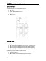
CONNECTIONS
The following connectors are located under the top cover
•
•
•
•
•
•
ADSL RJ-11
10 Base-T WAN (ETH/DMZ Port) RJ-45
LAN Port 1 RJ-45
LAN Port 2 RJ-45
LAN Port 3 RJ-45
LAN Port 4 RJ-45
INDICATORS
There are six indicators (LEDs) on the MDF cover.
•
•
•
•
•
•
Heartbeat – steady to indicate normal processor activity
ADSL - a solid light indicates ADSL line synchronisation – flashes with activity
LAN 1 - a solid light indicates an Ethernet connection – flashes with activity
LAN 2 - a solid light indicates an Ethernet connection – flashes with activity
LAN 3 - a solid light indicates an Ethernet connection – flashes with activity
LAN 4 - a solid light indicates an Ethernet connection – flashes with activity
An additional two indicators (LEDs) on the MDF indicate:•
•
2
Not used – permanently lit
WAN (ETH/DMZ) - a solid light indicates an Ethernet connection
BT Versatility
Broadband Module/Broadband Module Plus Manual
RESET BUTTON
The MDF is equipped with a white reset button. When this button is pressed, the moduleresets.
LOCAL AREA NETWORK
The module is equipped with a 4-port LAN with the following characteristics.
Feature
Description
Speed
10/100 Mb/s switched Ethernet
Mode
The LAN device can operate in FDX (Full Duplex) or HDX (Half Duplex)
mode.
MDI/ MDI-X
The port will automatically detect whether a straight or crossover cable is
used to connect the LAN device and will adjust itself accordingly.
Autosensing
The port will automatically adapt to the speed and mode of the device that is
connected to it.
Connectors
RJ-45
WIDE AREA NETWORK
PORTS
The module is equipped with the following ports for Wide Area Networking.
Port
MDF Interface
Description
ADSL
RJ-11
This is for "wires only" ADSL service. ITU-T G.992.1
Annex A (G.DMT) and ITU-T 992.2 (G.Lite) are supported.
ETH/DMZ Port
RJ-45
This port supports10/100 Ethernet, FDX/HDX, and is
used to connect to an external broadband gateway or
DMZ host.
It does not support MDI/MDI-X
ISDN
N/A
A single 64 kb/s dial-up connection can be established
over any ISDN line connected to the PBX.
3
BT Versatility
Broadband Module/Broadband Module Plus Manual
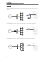
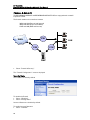
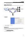
EXAMPLES
The on-board ADSL modem is used to connect to the Internet using a "wires only" service. See
page 10.
Splitter
Line
Internet
The ETH/DMZ port is used to connect to an external SDSL or Cable modem. See page 27.
Line
Internet
M
M
The ETH/DMZ port is used to connect to a Gateway into a private network. See page 27.
G
Private
Network
4
BT Versatility
Broadband Module/Broadband Module Plus Manual
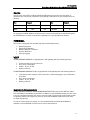
ROUTES
A single route using PPP (including PPPoE and PPPoA) and a second route using static or
dynamic IP are concurrently supported. The following combinations of ports and protocols are
possible.
Port
Protocol
ADSL Modem
ISDN
Port
Protocol
PPPoE/PPPoA
and
ETH/DMZ
IP
PPP
and
ETH/DMZ
IP
For example, the ADSL Modem could be used to connect to the Internet for web browsing and
the ETH/DMZ port could be connected to a gateway into a private wide area network.
FIREWALL
The module is equipped with a firewall that has the following features:
•
•
•
•
•
Stateful Inspection
Packet Filter Definition
Network Address Translation
Intrusion Detection
Security Logging
VOIP
The BROADBAND MODULE is equipped with a VoIP gateway with the following features:
•
•
•
•
2 endpoints which support IP trunks
Proxy server registration
Codecs - G.711, G.729
Quality of Service
The BROADBAND MODULE PLUS is equipped with a VoIP gateway with the following features:
•
•
•
•
12 endpoints which support trunks, extensions, unified messaging or any combination
of all three
Proxy server registration
Codecs - G.711, G.729
Quality of Service
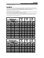
BANDWIDTH REQUIREMENTS
The BROADBAND MODULE and BROADBAND MODULE PLUS support two different codecs,
each with different bandwidth requirements. In addition to the bandwidth used by a codec, there
is also an overhead imposed by the various protocols used in transporting the IP packets as well
as signalling. When this is taken into account, the actual bandwidth required for each codec
increases significantly.
In order to ensure good voice quality, it is recommended that the following bandwidth is
available on the broadband connection for IP trunks and extensions
5
BT Versatility
Broadband Module/Broadband Module Plus Manual
Codec
IP Trunk or Extension
G.711
100 kb/s
G.729
50 kb/s
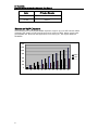
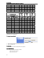
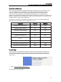
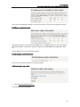
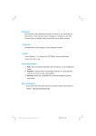
NUMBER OF VOIP CHANNELS
The following chart shows the bandwidth required to support up to 12 VoIP channels. When
calculating the number of VoIP channels that can be used over ADSL, always use the lower
(upload) data rate. Note that data applications for browsing etc., will require additional
bandwidth.
1400
1200
1000
800
G.711
600
G.729
400
200
0
1
6
2
3
4
5
6
7
8
9
10
11
12
BT Versatility
Broadband Module/Broadband Module Plus Manual
QUICK SETUP
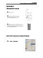
CONNECTING A PC TO THE LAN
Power up the PC
Connect the Ethernet port on the
PC to any LAN port (1 - 4) on the MDF
using a Cat 5 cable/patch cord.
Check that the LED on the MDF cover for the
port the PC is connected to, is lit permanently. This
indicates a good Ethernet connection between the
PC and the Broadband Module
ADSL
Port 1
Port 2
Port 3
Port 4
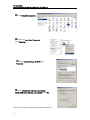
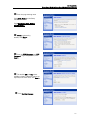
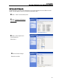
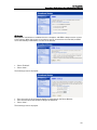
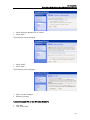
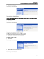
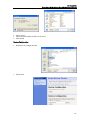
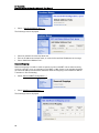
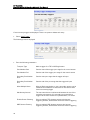
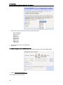
SET UP THE PC TO AUTOMATICALLY OBTAIN AN IP ADDRESS
Click Start and Control Panel
7
BT Versatility
Broadband Module/Broadband Module Plus Manual
Click Network Connections
Right click Local Area Connection,
Click Properties
Select Internet Protocol (TCP/IP), click
Properties
Select Obtain an IP address automatically,
Obtain DNS server address automatically, click OK
The PC is now set up to automatically obtain an IP address.
8
BT Versatility
Broadband Module/Broadband Module Plus Manual
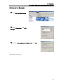
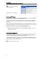
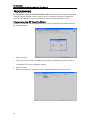
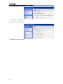
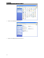
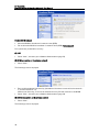
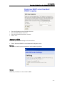
SETTING UP THE BROWSER
Click Tools, Internet Options
Select Connections, click LAN
Settings
Uncheck “Use a proxy server for your LAN”, click OK
The browser is now set up.
9
BT Versatility
Broadband Module/Broadband Module Plus Manual
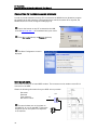
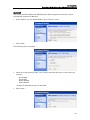
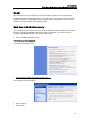
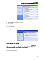
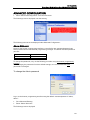
CONNECTING TO THE PROGRAMMING INTERFACE
In order to provide maximum security, PCs connected to the WLAN are not allowed to program
the module via the web interface. If programming from a wireless network PC is required, the
WLAN interface should be changed to LAN (page 51).
Launch the browser on any PC connected to the LAN,
enter 0Hhttp://192.168.1.1 in the address field, press return
Enter User name (admin) and Password (admin)
The Basic Configuration screen is
displayed
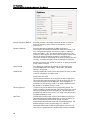
SETTING UP ADSL
The module contains an on-board ADSL modem. The connection to the modem is via an RJ-11
connector on the MDF.
Obtain the following information from your ADSL service provider:
Username
Password
Type of Access
VPI and VCI values
Connect the data port on the splitter to
the ADSL RJ-11 port on the MDF. Connect the
telephone port on the splitter to a telephone
or fax machine
10
Splitter
Line
BT Versatility
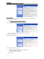
Broadband Module/Broadband Module Plus Manual
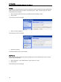
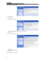
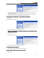
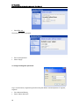
Enter the programming menu
Click ADSL Modem in the Setup
menu
Click Change the ADSL Modem
settings here …
PPPoA is selected by
default, click Next >
Enter the PPP Username and PPP
Password, retype the password, click
Next >
The default VPI and VCI values
(0/38) are shown, if different values are
required, enter them here, click Next >
Click Confirm Changes
11
BT Versatility
Broadband Module/Broadband Module Plus Manual
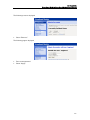
The new settings are displayed,
Restart the module
The ADSL setup is now complete.
SETTING UP IP TRUNKS
The following procedure is used to set up the BROADBAND MODULE and the BROADBAND
MODULE PLUS to operate with the BT Broadband Voice service.
A broadband connection must first be established before VoIP can be programmed. Refer to the
VoIP section (page 6) to find out how many IP trunks can be supported on your broadband
connection.
When you subscribe to the BT Broadband Voice service, you will be given a URL to link to and a
username and password. Connect to the URL from any PC on the LAN and enter the username
and password. The VoIP trunks will then be automatically configured.
To verify that the trunks have registered with the BT Broadband Voice service
•
Select “Status” from the main menu, scroll down to VoIP and verify that each trunk has
registered as indicated by .
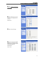
SETTING UP IP EXTENSIONS
The BROADBAND MODULE PLUS supports up to twelve IP endpoints which can be configured
as either trunks, extensions, or a combination of both. Note that when Unified Messaging
Service is required, one endpoint must be permanently assigned to it.
V-IP Featurephones must be used as local or remote extensions. (Note that other manufacturers
IP phones will not work with the system). Refer to the V-IP Featurephone Quick Reference User
Guide for setting up and connecting the phone.
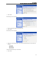
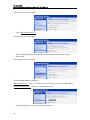
Select “VoIP” from the Setup menu
12
BT Versatility
Broadband Module/Broadband Module Plus Manual
Select Change VoIP Endpoint
types here …
Select ITP Extension for each
endpoint to be configured as an
extension
Select Next >
Select Confirm Changes
Enter the Password and MAC
address for each extension. The
MAC address is printed on a label
on the base of the V-IP
Featurephone.
Select Next>
13
BT Versatility
Broadband Module/Broadband Module Plus Manual
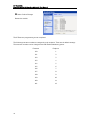
Select Confirm Changes
Restart the module
The IP Extension programming is now completed.
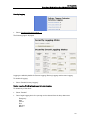
The following extension numbers are assigned to each endpoint. These are the default settings.
The extension numbers can be changed in the PBX Flexible Numbering option.
14
Extension
Endpoint
150
1
151
2
152
3
153
4
154
5
155
6
156
7
157
8
158
9
159
10
160
11
161
12
BT Versatility
Broadband Module/Broadband Module Plus Manual
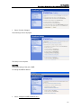
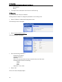
SETTING UP UM SERVICE
Unified Messaging provides email notification of voicemail messages left in the PBX voicemail
system. One IP endpoint must be permanently assigned to UM.
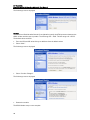
Select “VoIP” from the Setup menu
Select Change VoIP Endpoint
types here …
Select a free endpoint and
select UM Service
Select Next >
Select Confirm Changes
Restart the module
15
BT Versatility
Broadband Module/Broadband Module Plus Manual
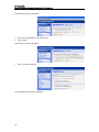
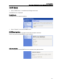
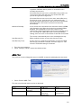
PROGRAMMING
All BROADBAND MODULE AND BROADBAND MODULE PLUS parameters can be programmed
using BT Versatility Wizard or via a browser on any PC connected to the LAN. The Welcome
screen and all subsequent screens presented are identical for both methods of access.
Programming from BT Versatility Wizard
Connect the PC with BT Versatility Wizard directly to the V.24 interface on the PBX and launch
BT Versatility Wizard.
•
Select “Connect”
•
On the pop-up menu select the COM port and speed. The default setting for the speed is
115,200 bps. This can be changed if required.
•
•
16
Select “Connect”
When the connection is established, select "Broadband Module" on the main menu
BT Versatility
Broadband Module/Broadband Module Plus Manual
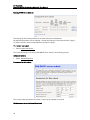
The Basic Configuration screen is displayed
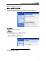
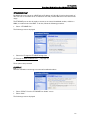
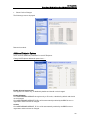
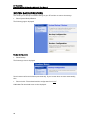
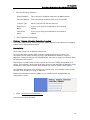
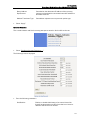
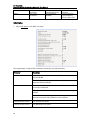
BASIC CONFIGURATION
The Basic Configuration screen shows the current Internet access settings as well as the
hardware and firmware versions.
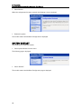
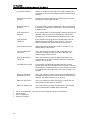
SETUP MENU
The Setup menu contains the following:
LAN Gateway
The LAN Gateway address is set by default to 192.168.1.1.
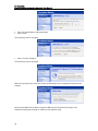
The following procedure is used to change this setting.
•
Select “LAN Gateway” in the Setup menu.
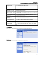
The following screen is displayed:
The current settings are shown.
•
Select “Change the Broadband Module address settings here …”
The following screen is displayed: -
17
BT Versatility
Broadband Module/Broadband Module Plus Manual
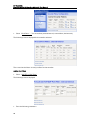
•
•
Enter the new IP address and Subnet Mask.
Select “Next”
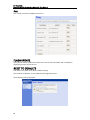
The following screen is displayed
•
Select “Confirm Changes”
The following screen is displayed
When the new parameters have been saved, the following screen is displayed showing the new
settings
Note that the DHCP Server address range for LAN hosts will automatically change in the
Advanced Configuration settings to reflect the new address range.
18
BT Versatility
Broadband Module/Broadband Module Plus Manual
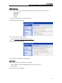
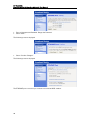
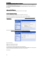
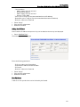
ADSL MODEM
To set up the ADSL modem, obtain the following information from your service provider.
- Type of Access
- Username
- Password
- VPI/VCI
•
Select “ADSL Modem” from the Setup menu.
The following screen is displayed
This screen shows the current settings.
•
Select “Change the ADSL Modem settings here …”
The following screen is displayed
Four options are presented for Type of Access:-
(1) PPPoA
This option uses Point-to-Point Protocol over ATM
•
•
Select “PPPoA” from the “ADSL Modem: Types of Access” screen
Select “Next”
The following screen is displayed
19
BT Versatility
Broadband Module/Broadband Module Plus Manual
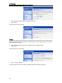
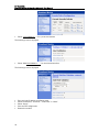
•
•
Enter a Username and Password. Retype the Password.
Select “Next”
The following screen is displayed.
VPI/VCI
VPI/VCI (Virtual Path Identifier/Virtual Circuit Identifier) specify the ATM connection between the
ADSL modem and the service provider. The VPI range is 0 – 4095. The VCI range is 0 – 65535.
The default values are 0/38
•
•
Enter the VPI and VCI values if they are different from the default values
Select “Next”.
The following screen is displayed
•
Select “Confirm Changes”
The new parameters are saved and the new ADSL Modem settings are displayed.
20
BT Versatility
Broadband Module/Broadband Module Plus Manual
•
Restart the module.
The ADSL Modem setup is now complete.
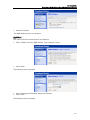
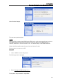
(2) PPPoE
This option uses Point-to-Point Protocol over Ethernet.
•
Select “PPPoE” from the “ADSL Modem: Types of Access” screen
•
Select “Next”
The following screen is displayed
•
•
Enter a Username and Password. Retype the Password.
Select “Next”
The following screen is displayed.
21
BT Versatility
Broadband Module/Broadband Module Plus Manual
VPI/VCI
VPI/VCI (Virtual Path Identifier/Virtual Circuit Identifier) specify the ATM connection between the
ADSL modem and the service provider. The VPI range is 0 – 4095. The VCI range is 0 – 65535.
The default values are 0/38
•
•
Enter the VPI and VCI values if they are different from the default values
Select “Next”
The following screen is displayed
•
Select “Confirm Changes”
The following screen is displayed
•
Restart the module
The ADSL Modem setup is now complete.
22
BT Versatility
Broadband Module/Broadband Module Plus Manual
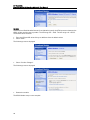
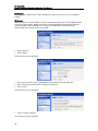
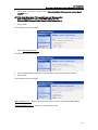
(3) DHCP
This option uses RFC 1483 Routed. DHCP (Dynamic Host Configuration Protocol) is used to
automatically obtain the IP addresses.
•
Select “DHCP” from the “ADSL Modem: Types of Access” screen
•
Select “Next”
The following screen is displayed
•
Select one of the following modes. Your service provider will advise you on the mode to be
selected
LLC Bridged
LLC Routed
VCMux Bridged
VCMux Routed
“Enable Link State Monitoring” should be ON
•
Select “Next”
23
BT Versatility
Broadband Module/Broadband Module Plus Manual
VPI/VCI
VPI/VCI (Virtual Path Identifier/Virtual Circuit Identifier) specify the ATM connection between the
ADSL modem and the service provider. The VPI range is 0 – 4095. The VCI range is 0 – 65535.
The default values are 0/38
•
•
Enter the VPI and VCI values if they are different from the default values
Select “Next”
The following screen is displayed
•
Select “Confirm Changes”
The following screen is displayed
•
Restart the module
The ADSL Modem setup is now complete.
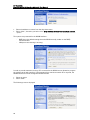
(4) Manual
This option uses RFC 1483 Routed. Static IP addresses will be provided by the service provider
and are manually entered.
•
•
Select “Manual” in the “ADSL Modem: Types of Access” screen.
Select “Next”
The following screen is displayed
24
BT Versatility
Broadband Module/Broadband Module Plus Manual
•
Select “Next”
The following screen is displayed
•
•
Enter the required IP addresses and Subnet mask.
Select “Next”
The following screen is displayed
•
Select one of the following modes. Your service provider will advise you on the mode to be
selected
LLC Bridged
LLC Routed
VCMux Bridged
VCMux Routed
“Enable Link State Monitoring” should be ON
•
Select “Next”
25
BT Versatility
Broadband Module/Broadband Module Plus Manual
The following screen is displayed
VPI/VCI
VPI/VCI (Virtual Path Identifier/Virtual Circuit Identifier) specify the ATM connection between the
ADSL modem and the service provider. The VPI range is 0 – 4095. The VCI range is 0 – 65535.
The default values are 0/38
•
•
Enter the VPI and VCI values if they are different from the default values
Select “Next”
The following screen is displayed
•
Select “Confirm Changes”
The following screen is displayed
•
Restart the module
The ADSL Modem setup is now complete.
26
BT Versatility
Broadband Module/Broadband Module Plus Manual
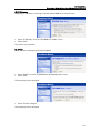
ETH/DMZ PORT
By default this port is set up as a DMZ with an IP address of 192.168.0.1 and a subnet mask of
255.255.255.0. The DHCP server is enabled on this and provides addresses in the same subnet
range.
The ETH/DMZ port can also be used to connect to an external broadband modem, a LAN or a
WAN, or to add a host to the DMZ. To do this, follow the following procedure:
•
Select “ETH/DMZ Port”
The following screen is displayed
•
Select the “Change the ETH/DMZ settings here …”
(To Change the DMZ IP address here …, see page 31)
Three options are presented
(1) PPPoE
PPPoE is used when connecting to an external broadband modem
•
•
Select “PPPoE” from the “ETH/DMZ Port: Mode” screen
Select “Next”
The following screen is displayed
27
BT Versatility
Broadband Module/Broadband Module Plus Manual
•
•
Enter a Username and Password. Retype the Password.
Select “Next”
The following screen is displayed
•
Select “Confirm Changes”
The following screen is displayed
The ETH/DMZ port is now set up to connect to an external ADSL modem.
28
BT Versatility
Broadband Module/Broadband Module Plus Manual
(2) IP Gateway
IP Gateway is used when connecting to another LAN or WAN via an external router.
•
•
Select “IP Gateway” from the “ETH/DMZ Port: Mode” screen
Select “Next”
Two options are presented :(a) DHCP
The IP address is automatically assigned by DHCP
•
•
Select “DHCP” from the “ETH/DMZ Port: IP Gateway Mode” screen
Select “Next”
The following screen is displayed
•
Select “Confirm Changes”
The following screen is displayed
29
BT Versatility
Broadband Module/Broadband Module Plus Manual
The setup is now complete.
(b) Static
Static IP addresses will be provided by the network administrator
•
•
Select “Static” from the “ETH/DMZ Port: IP Gateway Mode” screen
Select “Next”
The following screen is displayed.
•
•
Enter the required IP addresses and Subnet mask
Select “Next”
The following screen is displayed
30
BT Versatility
Broadband Module/Broadband Module Plus Manual
•
Select “Confirm Changes”
The following screen is displayed
The setup is now complete.
(3) DMZ
The default setting of the port is DMZ.
To change the DMZ IP address
•
Select Change the DMZ IP address here …
31
BT Versatility
Broadband Module/Broadband Module Plus Manual
The following screen is displayed
•
•
Enter the new IP address and subnet mask
Select “Next”
The following screen is displayed
•
Select “Confirm Changes”
The new address settings are displayed.
32
BT Versatility
Broadband Module/Broadband Module Plus Manual
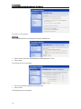
VOIP
Manually Configuring IP trunks
A broadband connection must first be established before the IP Endpoints can be programmed.
•
Select VoIP from the Setup menu
The following screen is displayed
•
Select Change VoIP Endpoint types here …
The following screen is displayed
•
•
Add - Trunk from the drop down menu for every endpoint to be configured as a trunk
Select Next
The following screen is displayed
33
BT Versatility
Broadband Module/Broadband Module Plus Manual
•
Select Confirm Changes
The following screen is displayed
•
•
Enter the Username and Password for each trunk
Select Next
The following screen is displayed
34
BT Versatility
Broadband Module/Broadband Module Plus Manual
•
Select Confirm Changes
The following screen is displayed
Restart the module.
Additional Endpoint Options
There are three additional parameters for each IP Endpoint:
Change VoIP Endpoint additional options here …
Enable Silence Suppression
This applies to IP trunks only, is disabled by default and should not be changed.
Enable RFC2833
On the BROADBAND MODULE this applies only to IP trunks, is disabled by default and should
not be changed.
On the BROADBAND MODULE PLUS it will be automativally enabled by the BBV Service on
registration and should not be changed.
Codecs
On the BROADBAND MODULE, G.711 will be automatically enabled by the BBV Service on
registration and should not be changed.
35
BT Versatility
Broadband Module/Broadband Module Plus Manual
On the BROADBAND MODULE PLUS, G.729 will be automatically enabled by the BBV Service
on registration and should not be changed.
For IP extensions, when the V-IP Featurephone is initially installed, the codec will be set by the
BT engineer.
Advanced VoIP Settings
These parameters are pre-configured and should not be changed.
Unified Messaging Settings
These parameters are pre-configured for use with BT e-mail services.
If you wish to use a different e-mail service provider, carry out the following.
Go to the main VoIP screen, scroll down and select the link Change Unified Communications
Settings here …
Select the link Change the Unified Communications address settings here …
Enter the following:
SMTP server name and port number
IMAP server name and port number
Your email service provider will provide the above information.
If synchronization is not provided by your service provider, leave the IMAP server name and port
number at their default settings (these fields must not be left blank).
Select Next >
36
BT Versatility
Broadband Module/Broadband Module Plus Manual
Select Confirm Changes
The new settings are displayed.
ISDN
Where the PBX is equipped with ISDN line(s), ISDN can be used to automatically back up the onboard ADSL modem in the event of line failure. In the case where no broadband service is
available, ISDN can be used for Internet access. The default setting is that ISDN is disabled.
Obtain the following information from your Internet Service Provider
Phone number to connect to the ISP
Username
Password
•
Select “ISDN” from the Setup menu
The following screen is displayed
•
Select “Change the ISDN settings here …”
Three options are presented for using ISDN :-
37
BT Versatility
Broadband Module/Broadband Module Plus Manual
(1) Disabled
With this option, ISDN is never used to establish an Internet connection. This is the default
setting.
(2) Backup
When this option is enabled, ISDN is used to automatically backup the on-board ADSL modem
in the event of line failure. When a line failure is detected, ISDN will wait 60 seconds before
backing up ADSL. When the ADSL line is restored, the ISDN call will be automatically
disconnected and browsing resumed over ADSL.
•
•
Select Backup
Select “Next”
The following screen is displayed
•
•
•
Enter the external line access digit (default is 9) followed by the Phone Number.
Enter the Username and Password. Retype the Password.
Select “Next”
The following screen is displayed
•
Select "Confirm Changes"
The following screen is displayed
38
BT Versatility
Broadband Module/Broadband Module Plus Manual
(3) Enabled
This option is used where no broadband service is available, and ISDN is always used to connect
to the Internet. When the browser is launched on any PC connected to the local LAN, an ISDN
call is automatically established to connect to the Internet.
•
•
Select “Enabled”
Select “Next”
The following screen is displayed:-
•
•
•
Enter the external call access digit (default is 9) followed by the Phone Number.
Enter the Username and Password. Retype the Password.
Select “Next”
The following screen is displayed
39
BT Versatility
Broadband Module/Broadband Module Plus Manual
•
Select "Confirm Changes"
The following screen is displayed
The ISDN setup is now complete.
40
BT Versatility
Broadband Module/Broadband Module Plus Manual
WLAN
This allows users to set up wireless PC connections and to configure their security settings.
The WLAN provides coverage at a range of up to 100 metres. This assumes clear line-of-sight
between a remote PC and the BBM. As the coverage is distance dependent, any obstruction
caused by walls etc will reduce the operating range.
Quick Setup to WLAN without security
This procedure should only be used to setup and test WLAN connectivity. When this procedure
has been completed and WLAN connectivity has been established, go to the next section
“Setting up WLAN with Security” and complete the process.
•
Select “WLAN” in the Setup menu
The following screen is displayed
Scroll down to General Settings
•
Select Enable or disable the wireless network here …
The following screen is displayed
•
•
Select “Enable”
Select “Next”
41
BT Versatility
Broadband Module/Broadband Module Plus Manual
The following screen is displayed
•
•
Note the SSID
Select “Next”
The following screen is displayed
•
•
Select “Allow the Broadband Module to select a channel”
Select “Next”
The following screen is displayed
•
•
•
Select “Off”
Check “Enable SSID Broadcast”
Select “Next”
The following screen is displayed
42
BT Versatility
Broadband Module/Broadband Module Plus Manual
•
•
Select “Allow any Wireless PCs to connect”
Select “Next”
The following screen is displayed
•
•
Select “DMZ”
Select “Next”
The following screen is displayed
•
•
Select “Confirm Changes”
Restart the module
Connecting your PC to the Wireless Network
•
•
Click Start
Click Control Panel
43
BT Versatility
Broadband Module/Broadband Module Plus Manual
•
Double click the Network Connections icon
•
Double click the Wireless Network Connection icon
44
BT Versatility
Broadband Module/Broadband Module Plus Manual
A list of wireless networks is displayed.
•
•
Select the SSID being broadcast by the module
Click “Connect”
You will now connect to the Wireless LAN.
Connected wireless PCs
Selecting the View details of connected wireless PCs … link under General Settings takes you to
the following screen which shows details of PCs connected to the WLAN
Setting up WLAN with Security
The recommended settings to provide maximum security are indicated as * Recommended.
Where instructed, enter the relevant information in the table provided in Appendix A as this
information is required when setting up PCs for wireless networking.
•
Select “WLAN”
The following screen is displayed
45
BT Versatility
Broadband Module/Broadband Module Plus Manual
First Time Settings
This automatically takes you through the configuration screens necessary for setting up the
wireless network for the first time.
•
Select “Change your wireless first time settings here …”
The following page is displayed
•
•
Select “United Kingdom” (default setting) from the drop-down menu
Select “Confirm Changes”
The following screen is displayed
Three WLAN Type options are presented:•
46
802.11 B/G (operates at 11 Mb/s or 54 Mb/s) *Recommended
802.11 B only (operates at 11 Mb/s)
802.11 G only (operates at 54 Mb/s)
Select an option
BT Versatility
Broadband Module/Broadband Module Plus Manual
•
Select “Confirm Changes”
The following screen is displayed
The default Network Name (SSID) is displayed.
This name can be changed if required.
Enter the Network Name (SSID) in the table provided in Appendix A as it is required when setting up
PCs for wireless networking.
•
Select “Next”
The following screen is displayed
Two options are presented for selecting a channel :(1) Allow Internet Module to select channel *Recommended
•
Select “Next”, this takes you to Security (page 47)
(2) Select a channel manually
•
Select “Next”
The following screen is displayed
•
•
Select a channel from the drop down menu
Select “Next”
The following screen is displayed
47
BT Versatility
Broadband Module/Broadband Module Plus Manual
Enable SSID Broadcast
•
•
Allow the WLAN to broadcast it’s network name (SSID)
Do not allow the WLAN to broadcast it’s network name (SSID) *Recommended
Four options are presented for security:(1) Off
•
Select “Next”, this takes you to Address Authentication (page 50)
(2) 64-bit encryption on the wireless network
•
Select “Next”
The following screen is displayed
•
•
Enter a 10 hexadecimal character key (hexadecimal characters consist of the characters A –
F, and the numbers 0 – 9).
Make a note of this key, as it must be entered into every PC that connects to the WLAN
Select “Next”, this takes you to Address Authentication (page 48)
(3) 128-bit encryption on the wireless network
•
Select “Next”
The following screen is displayed
48
BT Versatility
Broadband Module/Broadband Module Plus Manual
•
•
Enter a 26 character hexadecimal key (hexadecimal characters consist of the characters A –
F, and the numbers 0 – 9)
Make a note of this key as must be entered into every PC that connects to the WLAN
Select “Next”, this takes you to Address Authentication (page 48)
(4) Wi-Fi Protected Access (WPA) on the wireless network *Recommended
•
Select “Next”
The following screen is displayed
•
Enter a pass phrase of between 8 and 63 characters
Enter the Pass Phrase in the table provided in Appendix A as it is required when setting up
PCs for wireless networking.
•
Select “Next”
The following screen is displayed
Three options are presented for Address Authentication:(1) Allow any wireless PCs to connect
•
Select “Next”, this takes you to Select Interface (page 51)
(2) Allow all wireless PCs to connect except those I specify
•
Select “Next”
49
BT Versatility
Broadband Module/Broadband Module Plus Manual
The following screen is displayed
•
Select Add an address here …
The following screen is displayed
•
•
Enter the MAC address of the PC which is to be excluded from the wireless network
Select “Next”
The following screen is displayed
The entered MAC address is displayed
Add an address here … takes you back to the previous screen to enter another MAC address
Remove an address here … takes you to the following screen
•
50
Select the address to remove from the drop down menu
BT Versatility
Broadband Module/Broadband Module Plus Manual
•
Select “Next”, this takes you back to the “Allow all wireless PCs to connect except those I
specify” option
(2) Only allow the wireless PCs I specify to connect *Recommended
Refer to Appendix B to find out the MAC address of a PC
Enter the MAC Addresses in the table provided in Appendix A
•
Select “Next”
The following screen is displayed
•
Select add an address here …
The following screen is displayed
•
•
Enter the MAC address of the PCs to be allowed to connect to the wireless network
Select “Next”
The following screen is displayed
Add an address here … takes you back to the previous screen to enter another MAC address
Remove an address here … takes you to the following screen
51
BT Versatility
Broadband Module/Broadband Module Plus Manual
•
•
Select the address to remove from the drop down menu
Select “Next”, this takes you back to the “Only allow the wireless PCs I specify to connect
“option
Two options are presented for the WLAN Interface:-
DMZ (this is the default setting where the WLAN normally resides on the DMZ)
*Recommended
LAN (see screen warning re security)
In order to provide maximum security, PCs connected to the WLAN are not allowed to program
the module via the web interface. If programming from a wireless network PC is required, the
WLAN interface should be changed from DMZ to LAN.
•
•
Select an option
Select “Next”
The following screen is displayed
52
BT Versatility
Broadband Module/Broadband Module Plus Manual
The WLAN parameters are displayed
•
•
Select “Confirm Changes”
Restart the module
Go to Appendix A when setting up PCs for wireless networking
General Settings
These are used to change individual settings after the wireless network has been initially set up.
The links listed below allow you to change individual network settings used in the initial setup as
previously described
Change your wireless channel here …
Change your wireless network name here …
Change your wireless security settings here …
Change which wireless PCs are allowed to connect here …
Set the interface for the wireless network here …
Enable / Disable
Enable or disable the wireless network here …takes you the following screen
Two options are presented:-
53
BT Versatility
Broadband Module/Broadband Module Plus Manual
(1) Disable
•
Select “Next”
The following screen is displayed
•
•
Select “Confirm Changes”
Restart the module
(2) Enable
•
Select “Next”
This takes you through the procedure as described in First Time Settings
54
BT Versatility
Broadband Module/Broadband Module Plus Manual
STATUS
This displays the current status of the main system parameters.
55
BT Versatility
Broadband Module/Broadband Module Plus Manual
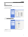
SYSTEM BACKUP/RESTORE
This allows you to backup the module settings to your PC and also to restore the settings.
•
Select System Backup/Restore
The following page is displayed
Backup Configuration
•
Select Backup
The following screen is displayed
Some browsers will start the backup automatically. If your browser does not start automatically,
then
•
Select the link “Please download the configuration from here.”
A Windows File download screen is then displayed.
56
BT Versatility
Broadband Module/Broadband Module Plus Manual
•
•
•
Select “Save”
Select the folder where the file is to be saved
Save the file
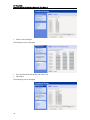
Restore Configuration
•
Browse for the configuration file
•
Select Open
57
BT Versatility
Broadband Module/Broadband Module Plus Manual
•
Select Restore
When the configuration has been restored, the following screen is displayed
•
Restart the system
The module restarts and the Basic Configuration is displayed.
SYSTEM RESTART
This allows you to restart the module.
•
Select System Restart from the menu
The following page is displayed
•
Select “Restart”
The module restarts and the Basic Configuration page is displayed.
58
BT Versatility
Broadband Module/Broadband Module Plus Manual
ADVANCED CONFIGURATION
•
Select “Advanced Configuration” from the main menu
The following screen is displayed, note the warning.
The following menu items are displayed under Advanced Configuration:-
ADMIN ACCOUNTS
Access to the browser programming interface is controlled by two username/password pairs
which provide the user with identical programming privileges. The default username/password
pairs are:
Username
Admin
Engineer
Password
Admin
Engineer
To change the passwords, carry out the following procedure using the browser programming
interface.
When changing the passwords from their default settings, it is recommended that both
passwords are changed.
To change the Admin password
Log in to the browser programming interface using the default username/password “admin,
admin”.
•
•
Go to Advanced Settings
Select “Admin Accounts”
The following screen is displayed
59
BT Versatility
Broadband Module/Broadband Module Plus Manual
•
Select Edit user …
The following screen is displayed
•
•
Enter a new password
Select “Apply”
To change the Engineer password
Log in to the browser programming interface using the default username/password “engineer,
engineer”.
•
•
60
Go to Advanced Setting
Select “Admin Accounts”
BT Versatility
Broadband Module/Broadband Module Plus Manual
The following screen is displayed
•
Select “Edit user”
The following page is displayed
•
•
Enter a new password
Select “Apply”
61
BT Versatility
Broadband Module/Broadband Module Plus Manual
FIREWALL & SECURITY
The BROADBAND MODULE and BROADBAND MODULE PLUS are equipped with a stateful
inspection firewall.
The firewall resides on the interfaces between
- WAN and LAN (External and Internal)
- WAN and DMZ (External and DMZ)
- DMZ and LAN (DMZ and Internal)
F/W
WAN
F/W
F/W
DMZ
•
Select “Firewall & Security”
The “Firewall Configuration” screen is displayed
Security State
The Firewall is enabled by default
To disable the Firewall
• Select “Disabled”
• Select “Change State”
Intrusion Detection is disabled by default.
To enable Intrusion Detection
• Select “Enabled”
62
LAN
BT Versatility
Broadband Module/Broadband Module Plus Manual
•
Select “Change State”
Security Level
There are four pre-defined security levels (high, medium, low and none) that contain different
security filters for each interface (WAN/LAN, WAN/DMZ, DMZ/LAN). When None is selected, all
traffic is blocked. Additional filters can be added to each security level as required.
The default setting is High Security Level.
The Medium Security level has additional filters. For example it is set up to allow access to a web
server or a mail server on the DMZ from the External interface.
The Low Security level adds more filters. For example, as well as allowing access to a web server
or a mail server on the DMZ, it also allows Telnet and FTP access from the External interface.
The pre-defined security configurations are:
High Security Level
(from any source IP address or any
source port)
Service
ICMP
Any
Any
RMCP
ISAKMP
SSL
Kerberos
Kerberos
HTTP
DNS
Telnet
SMTP
POP3
FTP
SSH
SIP
IPT
Destination Port
N/A
TCP
UDP
TCP
TCP
UDP
TCP
TCP
UDP
TCP
UDP
TCP
TCP
TCP
TCP
TCP
UDP
TCP
N/A
0 -65535
0 - 65535
50
51
500
443
88
88
80
53
23
25
110
21
22
5060 - 6000
5566
Medium Security Level
(from any source IP address or any
source port)
Service
ICMP
Any
Any
RMCP
ISAKMP
SSL
Kerberos
Kerberos
HTTP
Destination Port
N/A
TCP
UDP
TCP
TCP
UDP
TCP
TCP
UDP
TCP
N/A
0 - 65535
0 - 65535
50
51
500
443
88
88
80
External
<>
Internal
External
<>
DMZ
DMZ
<>
Internal
In
Out
In
Out
In
Out
F
F
F
F
F
F
F
F
F
F
F
F
F
F
F
F
T
T
T
T
T
T
T
T
T
T
T
T
T
T
T
T
T
T
T
T
F
F
F
F
F
F
F
F
F
T
T
F
F
F
F
T
T
T
T
T
T
T
T
T
T
T
T
T
T
T
T
T
T
T
T
T
F
F
F
T
T
T
T
T
T
F
T
F
F
F
F
T
T
T
T
T
T
F
F
F
F
F
F
T
T
T
T
T
T
F
T
T
External
<>
Internal
External
<>
DMZ
DMZ
<>
Internal
In
Out
In
Out
In
Out
F
F
F
F
F
F
F
F
F
F
T
T
T
T
T
T
T
T
T
T
F
F
F
F
F
F
F
F
F
T
T
T
T
T
T
T
T
T
T
T
F
F
F
T
T
T
T
T
T
F
T
T
T
F
F
F
F
F
F
T
63
BT Versatility
Broadband Module/Broadband Module Plus Manual
DNS
Telnet
SMTP
POP3
FTP
SSH
SIP
IPT
UDP
TCP
TCP
TCP
TCP
TCP
UDP
TCP
53
23
25
110
21
22
5060 - 6000
5566
Low Security Level
(from any source IP address or any
source port)
Service
ICMP
Any
Any
HTTP
FTP
SSH
Telnet
SMTP
RMCP
POP3
ISAKMP
SSL
Kerberos
Kerberos
DNS
SIP
IPT
Destination Port
N/A
TCP
UDP
TCP
TCP
TCP
TCP
TCP
TCP
TCP
TCP
UDP
TCP
TCP
UDP
UDP
UDP
TCP
N/A
0 - 65535
0 -65535
80
21
22
23
25
50
51
110
500
443
88
88
53
5060 - 6000
5566
F
F
F
F
F
F
T
T
T
T
T
T
T
T
T
T
External
<>
Internal
T
F
T
T
F
T
T
T
T
T
T
T
T
T
T
T
External
<>
DMZ
T
F
F
F
F
T
T
T
T
T
T
T
T
F
T
T
DMZ
<>
Internal
In
Out
In
Out
In
Out
F
F
F
F
F
F
F
F
F
F
F
F
F
F
F
F
T
T
T
T
T
T
T
T
T
T
T
T
T
T
T
T
T
T
T
T
T
F
F
T
T
T
T
T
F
F
T
F
F
F
F
T
T
T
T
T
T
T
T
T
T
T
T
F
T
T
T
T
T
T
T
T
T
F
F
T
T
T
T
F
T
T
F
T
T
T
T
T
T
T
T
T
T
T
T
F
T
T
F
F
T
F
F
F
F
T
T
T
Changing the security level deletes the previous security level and any filters set, and replaces
them with the new configuration.
To change the security level
•
•
Select the required level from the drop-down menu
Select “Change Level”
To add a filter
See section on Security Policy Configuration (see page 64)
Security Interfaces
Three security interfaces are defined by default
- ipwan (external) to internal
- ipwan (external) to dmz
64
BT Versatility
Broadband Module/Broadband Module Plus Manual
- ipdmz (dmz) to internal
NAT (Network Address Translation)
NAT operates independently on each interface and is enabled by default on each of the three
interfaces.
NAT
ipwan
internal
NAT
NAT
dmz
To disable NAT
•
•
Select “Disable NAT to … (Interface)”
Restart the module.
Global Address Pools
A global address pool is used to assign a range of public IP addresses to a WAN interface. This
can be used in conjunction with Reserved Mapping to associate the public IP addresses on the
WAN interface with specific servers/applications on the DMZ or LAN.
•
Select “Advanced NAT Configuration …”
The following screen is displayed
65
BT Versatility
Broadband Module/Broadband Module Plus Manual
•
Select “Add Global Address Pool …”
The following screen is displayed.
•
•
•
Select an interface from the drop down list
Enter an IP address and subnet mask, or enter the first and last IP addresses in the range
Select “Add Global Address Pool”
Reserved Mappings
Reserved mappings are used to create exceptions to the normal NAT rules to allow incoming
access to a specific server or application on the DMZ or LAN. A static route is defined between
an external IP address and internal IP addresses. Reserved mapping is also called Port address
Translation or Port Forwarding.
•
Select “Advanced NAT Configuration …”
•
Select “Add Reserved Mapping … ”
The following screen is displayed
66
BT Versatility
Broadband Module/Broadband Module Plus Manual
•
•
Enter the following parameters:
Global IP address
This is the public IP address assigned to the WAN interface
Internal IP Address
This is the internal IP address of the server on the LAN
Transport Type
Select a protocol from the drop down list
External Port
Range
A port or port range can be defined for the external IP
address
Internal Port
Range
A port or port range can be defined for the internal IP
address
Select “Add Reserved Mapping”
Policies, Triggers, Intrusion Detection, Logging
The security policy settings, stateful inspection triggers, intrusion policy detection and logging
settings can be displayed and changed.
Security Policy
Three types of filters can be defined in the firewall:
Port Filters are used to allow or block a specific TCP/IP application level protocol. The
parameters used to specify this filter are source and destination IP address or range of
addresses, a transport level protocol TCP/UDP/ICMP), and a port or range of ports which define
the application level protocol.
Raw IP Filters are used to allow or block a specific protocol (non TCP/IP) carried within an IP
packet. The parameters used to specify this filter are source and destination IP address or range
of addresses, and a protocol number which identifies the protocol carried in the IP packet.
Host Validators are used to block all traffic from a specific host. The parameter used to specify
this filter are an IP address or range of addresses.
Note that if invalid filter entries are added, an error message will be displayed when the
configuration is saved.
•
Select “Security Policy Configuration …”
The following screen is displayed.
67
BT Versatility
Broadband Module/Broadband Module Plus Manual
•
Select “Port Filters … ” for an interface (external/internal, external/dmz, dmz/internal)
The following screen is displayed for the interface selected
This screen lists the filters currently in effect for that interface.
Adding Port Filters
•
Select “Add TCP or UDP Filter”
The following screen is displayed
•
68
Enter the following parameters
BT Versatility
Broadband Module/Broadband Module Plus Manual
- Source address
- Mask is always 255.255.255.255
- IP Destination address
- Mask is always 255.255.255.255
- Protocol, TCP or UDP
- Source port or range of ports (associated with source IP address)
- Destination port or range of ports (associated with destination IP address)
- Direction, Inbound or Outbound
•
•
•
Select “Apply”
Save the new configuration
Restart the module
Adding Raw IP Filters
Filters based on IP address and protocol only can be added to the security level displayed.
• Select “Add Raw Filter”
The following screen is displayed
Enter the following parameters
- IP Source address and Subnet Mask
- IP Destination address and Subnet Mask
- IP Protocol
- Direction, Inbound or Outbound
•
•
•
Select “Apply”
Save the new configuration
Restart the module
Host Validators
Traffic to or from specific hosts can be blocked by the firewall.
69
BT Versatility
Broadband Module/Broadband Module Plus Manual
•
Select “Host Validators …” for a particular interface
The following screen is displayed
•
Select “Add Host Validator … ” for the selected interface
The following screen is displayed
•
•
•
•
•
70
Enter the host IP address and Subnet mask
Select the direction, “Inbound”, “Outbound” or “Both”
Select “Apply”
Save the new configuration
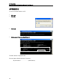
Restart the module
BT Versatility
Broadband Module/Broadband Module Plus Manual
Application Level Gateways
There are certain applications that NAT and Firewall configurations cannot manage. In many
cases, ALGs (Application Level Gateways) are needed to translate and transport packets
correctly. An ALG provides a service for a specific application such as FTP (File Transfer
Protocol). Incoming packets are checked against existing NAT rules or Firewall filters, IP
addresses are evaluated and detailed packet analysis is performed. If necessary, the content of a
packet is modified, and if a secondary port is required, the ALG will open one. The ALG for each
application does not require any configuration.
ALG support is provided for the following applications. If support is required for additional
applications, security triggers can be configured for these.
Application
TCP Port
UDP Port
AIM (AOL Instant Messenger)
5190
N/A
FTP (File Transfer Protocol)
21
N/A
IKE (Internet Key Exchange)
N/A
500
ILS (Internet Locator Service)
389 (+1002)
N/A
MSN (Microsoft Networks)
1863
N/A
PPTP (Point-to-Point Tunnelling
Protocol)
1723
N/A
RSVP (Resource Reservation Protocol)
N/A
N/A
L2TP (Layer 2 Tunnelling Protocol)
N/A
1701
SIP (Session Initiation Protocol)
5060
5060
Security Trigger
A security trigger can be defined for applications that are not supported by the ALGs listed
above. A security trigger allows the firewall to dynamically open and close secondary ports
associated with a particular application and to specify the maximum length of time the port
remains open.
•
Select “Security Trigger Configuration …”
The following screen is displayed
71
BT Versatility
Broadband Module/Broadband Module Plus Manual
Current security triggers are displayed. There is an option to delete each entry.
•
Select “New Trigger”
The following screen is displayed
•
72
Enter the following parameters
Transport Type
Adds a trigger for a TCP or UDP application
Port Number Start
Sets the start of the trigger port range for the control session
Port Number End
Sets the end of the trigger port range for the control session
Secondary Port Number
Start
Sets the start port range that the trigger will open
Secondary Port Number
End
Sets the end of the port range that the trigger will open
Allow Multiple Hosts
Allow or Block sets whether or not a secondary session can be
initiated to/from different remote hosts or the same remote
host on an existing trigger
Max Activity Interval
The max interval time in milliseconds between the use of the
secondary port sessions. If a secondary port opened by a
trigger has not been used for the specified time, it is closed
Enable Session Chaining
If this is enabled, TCP dynamic sessions also become
triggering sessions, which allows multi-level session triggering
UDP Session Chaining
If this is enabled, UDP dynamic sessions also become
triggering sessions, which allows multi-level session triggering
BT Versatility
Broadband Module/Broadband Module Plus Manual
•
Binary Address
Replacement
Sets whether the destination IP address of the incoming
packet is replaced with the associated internal IP address to
allow NAT traversal
Address Translation Type
Sets address replacement on a particular packet type.
Select “Apply”
Intrusion Detection
This is used to detect and block incoming attempts to attack or block traffic to the site.
•
Select “Configure Intrusion Detection … ”
The following screen is displayed
•
Enter the following parameters
Use Blacklist
Enables or disables blacklisting of an external host if the
firewall has detected an intrusion from that host. Access is
denied to that host for 10 minutes.
73
BT Versatility
Broadband Module/Broadband Module Plus Manual
•
•
•
•
74
Use Victim Protection
Enables or disables the blocking of incoming broadcast Ping
commands for the period specified in Victim Protection Block
duration.
Victim Protection Block
Duration
The period for which incoming broadcast Pings are blocked.
The default setting is 600 seconds.
DOS Attack Block
Duration
If a Denial of Service attack is detected, traffic from that host
is blocked for the duration specified here. The default setting
is 1800 seconds.
Scan Attack Block
Duration
If scan activity from a host attempting to identify open ports is
detected, traffic from that host is blocked for the duration
specified here. The default setting is 86400 seconds (1 day).
Scan Detection
Threshold
If the number of scanning packets counted within the Scan
Detection Period exceeds the value set here, a port scan
attack is detected. The default setting is 5 per second.
Scan Detection Period
The duration that scanning type traffic is counted for. The
default setting is 60 seconds.
Port Flood Detection
Threshold
This is the maximum number of SYN packets that can be
received by a single port before a flood is detected. The
default setting is 10 per second.
Host Flood Detection
Threshold
This is the maximum number of SYN packets that can be
received from a host before a flood is detected. The default
setting is 20 per second.
Flood Detection Period
If the number of SYN floods counted within this duration
exceeds either the Port Flood Detection Threshold or the Host
Flood Detection Threshold, traffic from the attacker is blocked
for the DOS Attack Block Duration. The default setting is 10
seconds.
Maximum TCP Open
Handshaking Count
This is the maximum number (per second) of unfinished TCP
handshaking sessions that are allowed before a DOS attack is
detected. The default setting is 5 per second.
Maximum Ping Count
This is the maximum number of Pings (per second) that are
allowed before a DOS attack is detected.
Maximum ICMP Count
This is the maximum number of ICMP packets (per second)
that are allowed before a DOS attack is detected.
Select “Clear Blacklist” if you wish to clear all external hosts from the blacklist.
Select “Apply”
Save Configuration
Restart the module
BT Versatility
Broadband Module/Broadband Module Plus Manual
Security Logging
•
Select “Configure Security Logging …”
The following page is displayed
Logging is enabled by default for Session Logging, Blocking Logging and Intrusion Logging.
To disable all logging:
•
Select “Disable Security Logging”
Session Logging, Blocking Logging and Intrusion Logging.
To disable any of the above
•
Select “Disable”
•
One of eight logging levels for reporting can be selected from the drop down menu
Emergency
Alert
Critical
Error
Warning
Notice
75
BT Versatility
Broadband Module/Broadband Module Plus Manual
Informational
Debug
•
The output can be directed to the Console or the Event Log.
IP ROUTES
This allows static IP routes to be defined.
Existing routes are listed. To change the parameters on an existing route
•
Select “IP Routes” in Advanced Configuration menu
The following screen is displayed
•
Select “Create new IP V4 route …”
The following page is displayed
•
Enter the following parameters:
- Destination IP address
- Gateway IP address
- Netmask
- Cost – this sets the number of hops counted as the cost of the route.
- Interface – choose from the following:
ipwan
ipdmz
iplan
None
- Advertise – true or false
•
Select “OK”
The list of routes is displayed again.
76
BT Versatility
Broadband Module/Broadband Module Plus Manual
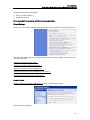
DHCP SERVER
•
Select “DHCP Server” in the Advanced Configuration menu
The DHCP Server is displayed
Enable/Disable
The DHCP server is enabled by default.
•
Select “Disable” to turn off the DHCP server.
DHCP Server Interfaces
By default the DHCP server operates on the iplan and ipdmz interfaces.
There is an option to delete DHCP on each interface.
Add new interface
There is an option to tell the DHCP server to operate on the ipwan interface.
77
BT Versatility
Broadband Module/Broadband Module Plus Manual
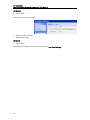
Existing DHCP Server Subnets
The settings for the existing subnets on the iplan and ipdmz are displayed.
All displayed parameters can be changed – change the setting to a new value and click “Apply”.
To delete a subnet, check the associated box and select “Apply”.
To create a new subnet
•
Select Create new subnet …
The screen displayed is the same as Edit DHCP server subnet in the following section.
Advanced Options
•
Select Advanced Options
Parameters for this subnet
The current subnet parameters are shown. These can be changed as required.
IP addresses to be available on this subnet
78
BT Versatility
Broadband Module/Broadband Module Plus Manual
The range of IP addresses available on the subnet is shown. These can be changed if required.
DNS Server option information
The default setting is use local host as the DNS server - all DNS requests are sent to the default
gateway 192.168.1.1 which then relays the request to the DNS addresses negotiated at start
up.
Specific DNS servers can be defined if required.
Default gateway option information
Use local host as default gateway is checked by default.
Additional option information
•
Select Create new DHCP option …
The following screen is displayed
79
BT Versatility
Broadband Module/Broadband Module Plus Manual
•
Select one of the following options from the drop down menu:
Default gateway
Domain name
IRC server
HTTP server
SMTP server
POP3 server
NNTP server
WINS server
Time server
•
•
Enter the option value in the field below.
Select OK
To always assign the same IP address to a host
The same IP address will always be assigned to a specific host with the specified MAC address.
•
Select “Create new Fixed Host …”
The following screen is displayed
80
BT Versatility
Broadband Module/Broadband Module Plus Manual
•
•
•
•
Enter the IP address to be assigned to the host
Enter the MAC address of the host
Enter the maximum lease time in seconds
Select “OK”
ADVANCED ISDN
Additional optional ISDN settings can be entered here.
•
Select "Advanced ISDN" from the Advanced Configuration menu
Call Log
This option is used for system maintenance and is disabled by default.
Options
Additional parameters can be entered for ISDN
81
BT Versatility
Broadband Module/Broadband Module Plus Manual
Backup Telephone Number
If the ISP provides a secondary telephone number for Internet
access in case the primary number is unavailable, it can be
entered here.
Number of Retries
If the first attempt to establish an ISDN connection is
unsuccessful, the module automatically redials the number. The
user configures the number of times the number is redialled
within the range 1 - 255. The default setting is 30 retries. The
number of retries applies first to the main telephone number and
then to the backup telephone number if it is enabled. If a
connection cannot be established on the backup number after the
last retry, no further attempt is made to establish a connection.
No limit is placed on the number of retries if ' 0' (zero) is specified
as the number of retries.
Retry Interval
This defines the time interval between retry attempts and is
programmable within the range 5 - 60 seconds. The default
setting is 10 seconds.
Initial Period
During an ISDN call a timer is set to disconnect the call if no data
is sent or received for a period of time.
Three timers are used:
The Initial Period defines the period from the start of the call to
the end of the initial billing period. This can be set by the user to
the initial billing period of the ISDN call. This information is
available from the service provider. The range is between 0 and
60 minutes. The default setting is 3 min.
Recurring Period
The Recurring period defines the recurring billing period. The
range is between 0 and 60 minutes. This can be set by the user to
the recurring billing period of the ISDN call. This information is
available from the service provider. The range is 0 to 60 minutes.
The default setting is 3 min.
Idle Timer
The Idle timer monitors the call for a period before the expiry of
the initial billing period and subsequent recurring periods. If no
data is present during the idle timer period, the call is
automatically disconnected at the end of that billing period. The
default setting is 30 secs and the range is 0 - 120 secs.
If the Initial Period and the Recurring Period are set to zero, no
cost control is applied and the call will always remain connected
82
BT Versatility
Broadband Module/Broadband Module Plus Manual
regardless of whether data is present or not until the call is
manually disconnected.
If the Initial Period is set to zero, and the Recurring period is set
to a non-zero value, then the call is only monitored for idle
periods during the Recurring Period.
If the Initial Period is set to a non-zero value, and the Recurring
Period is set to zero, then the call is only monitored for idle
periods during the Initial Period. If the call is still connected after
the Initial Period, it will remain connected until manually
disconnected.
Maximum Calls/day
A call counter sets a threshold on the maximum number of ISDN
calls allowed per day. When this threshold is exceeded, ISDN is
disabled. This is designed to control the number of calls
inadvertently made by applications without the knowledge of the
user. The range is 0 -1000. When this is set to 0 (the default
setting), there is no limit on the number of calls that can be made.
The counter is automatically set to zero at midnight each day.
Auto Recovery On
When enabled, the auto recovery timer becomes active.
Auto Recovery Timer
A timer option is provided to automatically re-enable the ISDN
after the retry threshold is reached. The timer range is 1 - 120
minutes. The default setting is 30 minutes.
•
•
Enter the new parameters
Select "Change" ("Reset" restores the default values)
ADSL TEST
This performs a series of diagnostic tests on the ADSL connection and displays the test results.
•
Select “Perform ADSL Test”
The tests are performed and the results are displayed.
Result
Test
Diagnostic
Cause
Passed
User diagnostics
complete
Physical connection
-
ADSL connection OK
WAN port
connecting:
handshaking
ADSL line
disconnected
Failed
83
BT Versatility
Broadband Module/Broadband Module Plus Manual
Aborted
Failed
User’s ppp
connection
User’s ppp
connection
Configuration
changed during test
ppp connection
establish
Incorrect username or
password
Incorrect protocol
(Type of Access)
Incorrect VPI or VCI
DSL Status
•
Select DSL Status on the ADSL Test page
This page displays a range of DSL parameters indicating line speed and quality.
Parameter
Description
Operational Mode
Inactive – the line is disconnected or the DSL modem is negotiation
with the DSLAM
G.DMT or T1.413 - indicates the DSL standard that has been
negotiated with the DSLAM
State
Showtime – the line is synchronised and the ADSL connection is
successfully established
Training - the ADSL modem is negotiating line speed with the
DSLAM
Handshake - the handshaking procedure is taking place to
determine the nature and capabilities of the endpoints
Trained transmit bit rate
The upstream line speed
Trained transmit bit rate
The downstream line speed
84
BT Versatility
Broadband Module/Broadband Module Plus Manual
Upstream power
The output power of the ADSL modem
Local/Remote fast channel
FEC error count
The fast channel Forward Error Correction error count measured at
the near/far end
Local/Remote interleaved
channel FEC error count
The interleaved channel Forward Error Correction error count
measured at the near/far end
Local/Remote fast channel
CRC
The fast channel Cyclic Redundancy Check error count measured at
the near/far end
Local/Remote interleaved
channel CRC
The interleaved channel Cyclic Redundancy Check error count
measured at the near/far end
Local/Remote line
attenuation
The line loss measured at the near/far end
Local/Remote signal-tonoise margin
The signal-to-noise ratio measured at the near/far end
Local/Remote LOS
The number of occurrences of Loss of Signal at the near/far end
Local/Remote SEF
The number of Severely Errored Frames received at the near/far
end
DIAGNOSTICS
This is used for system maintenance and contains the following diagnostic tools.
Event Log
Shows system related events. This provides diagnostic information.
85
BT Versatility
Broadband Module/Broadband Module Plus Manual
PING
This is used to test the broadband connection.
FLASH UPDATE
This option is used to update the module with a new version of firmware and is available to
engineering support personnel only.
RESET TO DEFAULTS
This resets the module to the factory default settings.
Select “Reset to Defaults” from the Advanced Configuration menu
The following screen is displayed
86
BT Versatility
Broadband Module/Broadband Module Plus Manual
Check the “Confirm” box
Select “Reset to Defaults”
The default settings are restored.
87
BT Versatility
Broadband Module/Broadband Module Plus Manual
APPENDIX A
Setting up wireless networking on a PC using the recommended settings in WLAN setup
Enter the settings used in the initial WLAN setup (page 44) in the table below. Refer to this table
when setting up PCs to connect to the WLAN
Network Name / SSID
WPA Pass Phrase
PCs Allowed to connect to WLAN
MAC Address (1)
MAC Address (2)
MAC Address (3)
MAC Address (4)
MAC Address (5)
MAC Address (6)
MAC Address (7)
MAC Address (8)
This procedure describes setting up WPA security on a PC with Windows XP.
For other operating systems, please consult your PC user manual.
Note that some older wireless LAN adapters do not support WPA.
•
•
88
Click “Start” on the task bar of the PC
Click “Control Panel”
BT Versatility
Broadband Module/Broadband Module Plus Manual
•
Double click the Network Connections icon
•
Double click the Wireless Network Connection icon
89
BT Versatility
Broadband Module/Broadband Module Plus Manual
A list of wireless networks is displayed.
•
Click Change the order of preferred networks
•
Click Add
90
BT Versatility
Broadband Module/Broadband Module Plus Manual
•
Enter the network name (SSID) (this is the Network Name (SSID) entered in the WLAN
settings in p.43)
•
Select WPA-PSK from the Network Authentication drop-down menu
•
Select TKIP from the Data encryption drop-down menu
•
Enter the network key (this is the Pass Phrase entered in the WLAN settings in p.46)
•
Confirm the network key
•
Click OK
91
BT Versatility
Broadband Module/Broadband Module Plus Manual
APPENDIX B
To find out the MAC address of a PC
•
•
Click start
Click Run
•
Enter cmd
•
At the prompt > type ipconfig/all [return]
The MAC address is displayed under
Ethernet adapter Wireless Network Connection:
Physical Address . . . . . . . . . . . . : (MAC address)
92
BT Versatility
Broadband Module/Broadband Module Plus Manual
Index
Admin, 33
ADSL, 8
ADSL Health Check, 50
Advanced Configuration, 32
Advanced NAT Configuration, 37
Auto configuration, 12
Application Level Gateways, 42
ATM, 14
Basic Configuration,
Blacklist, 45
Codecs, 5, 29
Connections, 3
DHCP, 11, 18
DMZ, 28
DOS Attack, 45
DSL/Broadband, 2
ETH/DMZ Port, 4, 28
Event logging, 39
filter, 36
Firewall, 2, 5, 34
Fixed Host IP Address, 49
Global Address Pools, 37
Host Validators, 41
ICMP, 46
Indicators, 3
Installation, 2
Intrusion Detection, 5, 35, 44
IP Gateway, 25
ISDN, 2, 41, 65
LAN Gateway, 9
Local Area Network, 2, 4
Event Logging, 5
Management, 2
Manual addressing, 20
MDF, 2
NAT, 36
Network Address Translation, 5, 36
BT Versatility Wizard, 6
Packet Filter, 5
Password, 7
Ping, 46
Port, 4, 40
Port Flood attack, 45
PPPoA, 13
PPPoE, 15
Programming, 6
Quality of Service, 5
Raw Filter, 40
Registrar Proxy, 29
Reserved Mappings, 38
Reset Button, 4
routes, 4, 38
Security State, 35
Security Level, 35
Security Interfaces, 34, 36
Security Trigger, 43
SIP, 29
Static IP address, 26
Username, 7
Victim Protection, 45
VoIP, 2, 5, 29
VPI/VCI, 14
Wide Area Network, 2, 4
Wireless Networking 42
93
BT Versatility
Broadband Module/Broadband Module Plus Manual
BT Versatility BROADBAND MODULE
/BROADBAND MODULE PLUS Manual
Issue 3, July 2007
Part number LR 2731.31001-3
The CE Marking on this equipment indicates
Compliance with the following
This device conforms to Directive 1999/5/EC
on Radio Equipment and Telecommunications
Terminal Equipment as adopted by the
European Parliament And Of The Council
Offices Worldwide
The telecommunications services described in this publication are
subject to availability and may be modified from time to time.
Services and equipment are provided subject to British
Telecommunications plc’s respective standard conditions of
contract.
Nothing in this publication forms any part of any contract.
© British Telecommunications plc 2008.
Registered Office: 81 Newgate Street, London EC1A 7AJ.
Registered in England No: 1800000.
Produced by BT Business Information Systems Marketing
Cover designed by H&P Graphics Limited (9968).
PHME 42397/05/05
Part No. 2731.31000-4
Printed on paper which meets international environmental
standards