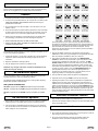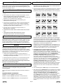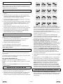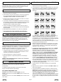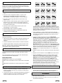
1
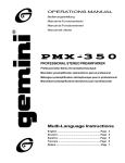
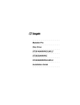
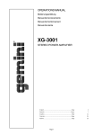
UX-160 UHF Wireless System with 15 Selectable Frequencies and One Mic-Transmitter Einkanalige Drahtlose UHF Über tragungsanlage mit 15 wählbaren Frequenzen und einem Mikrofon-Sender Sistema UHF inalámbrico con 15 frecuencias disponibles y un transmisor-micrófono Système sans fil UHF 15 fréquences sélectionnables et un émetteur à micro Sistema di radiotrasmissione UHF con 15 frequenze selezionabili e radiomicrofono Operations Manual Bedienungsanleltung Manual de funcionamiento Manual de fonctionnement Manual del utente English.......................................................................................Page Deutsch.....................................................................................Page Español......................................................................................Page Francais.....................................................................................Page Italiano.......................................................................................Page EUROPE 1 3 5 7 9 Introduction Congratulations on purchasing a Gemini wireless system. This state of the art unit includes the latest features backed by a three year limited warranty. Prior to use, we suggest that you carefully read all the instructions. Cautions 1. All operating instructions should be read before using this equipment. 2. To reduce the risk of electrical shock, do not open the unit. There are NO USER REPLACEABLE PARTS INSIDE. Please refer servicing to a qualified service technician. 3. Do not expose this unit to direct sunlight or to a heat source such as a radiator or stove. 4. Dust, dirt and debris can interfere with the performance of this unit. Make an effort to keep the unit away from dusty, dirty environments, and cover the unit when it is not in use. Dust it regularly with a soft, clean brush. 5. When moving this equipment, it should be placed in its original carton and packaging. This will reduce the risk of damage during transit. 6. DO NOT EXPOSE THIS UNIT TO RAIN OR MOISTURE. Set the dip switches on the receiver and the belt pack transmitter or hand held mic transmitter to matching frequencies. The dip switches for the receiver are located on the front panel. The dip switches for the belt pack transmitter are located on the side of the belt pack. The dip switches for the hand held mic can be accessed by opening the battery holder on the side of the mic. 7. DO NOT USE ANY SPRAY CLEANER OR LUBRICANT ON ANY CONTROLS OR SWITCHES. Note If this equipment causes interference to radio or television reception, try one or more of the following suggestions: 1. Change the frequency you are using to another one of the 15 selectable frequencies. See the instructions for selecting frequencies for more information. 3. Plug the AC adapter into the rear of the receiver where the jack is labeled DC 12-18V. Then plug the adapter into an appropriate AC outlet. Note: The adapter is available in 120V AC or 230V AC. 4. The receiver is supplied with 2 output jacks. The UNBALANCED OUTPUT is used to connect the receiver to your amp, effects or mixer mic jack using a standard mic cable with a 1/4” connector. The BALANCED OUTPUT is used to connect the receiver to your amp, effects or mixer mic jack using a standard mic cable with a XLR connector. We recommend using the balanced output if the cable to your amp, effects or mixer mic jack is 10 feet or more. The BALANCED OUTPUT has three separate conductors, two of which are signal (positive and negative) and one shield (ground). Pin 1 is ground (shield). Pin 2 is signal hot (positive). Pin 3 is signal cold (negative). 2. Repoint or relocate the receiving antenna. 3. Plug the equipment into a socket on a different circuit. Remember, any changes made to the unit without authorization from Gemini will void your warranty. UX-160 Wireless System The UX-160 wireless system is a high quality audio product that provides excellent performance under most operating conditions. 5. Point the antenna upward. Switch the power to the ON position. The different systems available all operate on a UHF high band frequency between 863.125 MHZ to 864.875 MHZ. 7. Adjusting the squelch on the receiver can eliminate such problems as bleeding that occurs from using several systems at the same time or interference from local television. To adjust the squelch, place the small plastic tool (included with the unit) in the hole marked SQUELCH at the back of the unit, and slowly turn the tool to adjust the output level to just above the level of background noise. Setting the squelch too high will reduce the range of the system. Setting the squelch too low will increase the level of unwanted noise. 6. Adjust the volume using the LEVEL control on the front panel. The systems available are: UX-160M - equipped with the UM-68 hand held microphone transmitter. UX-160L - equipped with the UB-68L belt pack transmitter with lavalier mic. UX-160H - equipped with the UB-68H belt pack transmitter with headset mic. UX-160 Receiver Operation 1. Remove all the packing materials. Save the box and packing material to transport the unit in the unlikely event that the unit requires service. Hand Held Transmitter Features • High sensitivity cardioid capsule for professional use • Special noise absorption material inside the mic barrel eliminates switch shock and handling noise 2. The UX-160 has 15 selectable frequencies so that you can choose the one with the least amount of interference. The illustration shows the dip switch settings for the 15 frequencies. Cautions 1. Do not drop the microphone element. 2. Do not strike the microphone element with your fist or fingers, and do not blow strongly into the microphone head front. 3. Do not use the microphone in areas of high humidity and/or high temperature as this could lead to damage of the microphone. EUROPE Page 1 EUROPE Hand Held Transmitter Operation Specifications 1. Open the battery holder. Insert 2 AA batteries into the battery holder according to the polarity indication marked on the battery housing. Close the battery holder. 2. Push the power switch to the ON position. The BATT indicator should flash once briefly as you turn on the mic indicating that the mic has sufficient power. If the BATT stays on, it indicates that the batteries have insufficient power and should be changed. If the BATT does not light at all and the mic does not work, it indicates that the batteries are either dead or not positioned correctly, and you should correct the positioning or change the batteries. If the microphone is not going to be used for any length of time, push the power switch to OFF and remove the batteries. Do not switch the mic on and off rapidly, because you won’t get a true indication from the BATT indicator. Lavalier Mic Features • Heavy duty strain relief • Foam wind screen • Tie clip Frequency Range.........................................................863.125 ~ 864.875 MHz RF Power Output.........................................................................30 mW max. Oscillation Mode.............................................................PLL Synthesized Frequency Stability............................................................................± 0.005% T.H.D.......................................................................................< 0.5% @ 1 kHz LED Indicator...............................................Power ON-OFF and low battery Current Consumption..........................................................65 mA @ 2.4V Batteries....................................................................................................2 AA Headset Mic Features Heavy duty strain relief • Headset • Foam wind screen Frequency Range........................................................863.125 ~ 864.875 MHz Receiving System..................................................................PLL Synthesized Receiving Mode........................................................................single channel Frequency Stability.............................................................................± 0.005% Signal to Noise Ratio...............> 94 dB @ 15 kHz and 60 dBµV antenna input Dynamic Range......................................................................................> 96dB AF Response..............................................................40 Hz - 15 kHz (±3 dB) T.H.D..................................................................................< 1.0% @ 1 kHz Audio Output..............................................unbalanced; 0 dB (0 dB=0.775V) at 48 kHz reference RF deviation balanced; -20 dB (0 dB=0.775V) Power Supply.........................................................................D.C. 12~18 V Dimensions........................2" (H) x 8.27” (W) x 6.5" (D) (51 x 210 x 166 mm) Transmitter (all models): Note: The lavalier mic clip should be placed on the center of your shirt just below your collarbone. • Receiver: Transmitter (hand held): Microphone Element..........................................................................Dynamic Dimensions................................................10.7" (L) x 2.4” (D) (272 x 62 mm) Transmitter (belt pack): Microphone Element........................................................................Condenser Dimensions...................................4" (H) x 2.6” (W) x 1" (D) (98 x 66 x 25 mm) Belt Pack Transmitter Operation 1. Open the battery door by sliding towards the arrow. Insert 2 AA batteries into the battery holder according to the polarity indication marked on the battery housing. Close the battery door. 2. Connect the mic to the belt pack transmitter. 3. Push the power switch to the ON position. The LOW BATT indicator should flash once as you turn on the belt pack indicating that the transmitter has sufficient power. If the LOW BATT stays on, it indicates that the batteries have insufficient power and should be changed. If the LOW BATT does not light at all, it indicates that the batteries are either dead or not positioned correctly, and you should correct the positioning or change the batteries. If the transmitter is not going to be used for any length of time, push the power switch to OFF and remove the batteries. 4. To adjust the gain (input sensitivity), place the small plastic tool (included with the unit) in the hole marked gain on the side of the belt pack and slowly turn the tool and speak into the mic until the volume is adjusted. Use of any other tool to adjust the gain will void the warranty. Hint: If the audio signal’s sound is distorted, try turning the gain down on your belt pack transmitter and/or your mixer, and increase the volume output on the receiver. EUROPE Page 2 EUROPE Einführung Betrieb des UX-160 Empfängers Wir bedanken uns für Ihre Wahl einer Drahtlosen Übertragungsanlage von Gemini. Dieses innovative Gerät mit drei Jahren Herstellergarantie bietet alle aktuellen Funktionen. Bitte lesen Sie diese Bedienungsanleitung, bevor Sie das Gerät in Betrieb nehmen. 1. Entfernen Sie alle Verpackungsmaterialien. Bewahren Sie den Originalkarton für einen späteren Transport auf, im unwahrscheinlichen Fall, daß Ihr Gerät wartungsbedürftig wird. 2. Die UX-160 Anlage verfügt über 15 auswählbare Frequenzen, so daß Sie diejenige auswählen können, welche die geringste Störung verursacht. Die Abbildung zeigt die Dip-Schaltereinstellungen für die 15 Frequenzen. Hinweise zur Sicherheit 1. Lesen Sie diese Bedienungsanleitung vor der Inbetriebnahme vollständig durch. 2. Um die Gefahr eines elektrischen Schlages auszuschließen, darf das Gerät nicht geöffnet werden. Dieses Gerät enthält KEINE AUSTAUSCHBAREN KOMPONENTEN. Wenden Sie sich im Falle einer Reparatur an eine qualifizierte Service-Werkstatt. 3. Setzen Sie das Gerät keiner direkten Sonnenstrahlung oder Wärmequellen wie Heizungen aus. 4. Da die Leistung des Gerätes durch Staub und Schmutz beeinträchtigt werden könnte, sollten Sie es immer in einer sauberen Umgebung einsetzen und bei Nichtbenutzung abdecken. Reinigen Sie das Gerät regelmäßig mit einem weichen, sauberen Pinsel. 5. Das Gerät sollte im Originalkarton transportiert werden, um Beschädigungen zu vermeiden. 6. SETZEN SIE DAS GERÄT NIEMALS REGEN ODER FEUCHTIGKEIT AUS. 7. VERWENDEN SIE KEINE REINIGUNGSSPRAYS ODER SCHMIERSTOFFE FÜR DIE SCHALTER UND REGLER. Gesetzliche Bestimmungen zum Betrieb Die Dip-Schalter auf dem Empfänger, Gürtelsender oder HandmikrofonSender auf die entsprechenden Frequenzen justieren. Die Dip-Schalter für den Empfänger befinden sich auf der Frontplatte. Die Dip-Schalter für den Gürtelsender befinden sich an der Seite des Gürtelsenders. Die DipSchalter für das Handmikrofon sind zugänglich, indem Sie den Batteriehalter an der Seite des Empfängers öffnen. Die drahtlosen Übertragungsanlagen von Gemini sind laut neuesten R&TTE-Bestimmungen und EMV- und CE-Vorschriften, geprüft und in der BRD zulässig. Die Anwender und Besitzer von Gemini-Geräten sind selbst für deren örtliche Zulassung verantwortlich, die Zulassungsfähigkeit der jeweiligen Geräte hängt ganz von ihrer Klassifizierung und Anwendung ab. Hinweis Dieses Gerät ist getestet worden und entspricht den gültigen EMV- und CEVorschriften. Diese Anlage arbeitet auf einer von den Behörden zugelassenen Frequenz. Es kann jedoch nicht garantiert werden, daß bei einer bestimmten Installation keine Störungen auftreten werden. Falls diese Anlage bei Radio-, Fernsehempfang oder anderen Einflüssen Störungen verursacht, versuchen Sie bitte folgendes: 1. Schalten Sie die gegenwärtige Frequenz auf eine andere der 15 auswählbaren Frequenzen um. Weitere Informationen finden Sie in den Anweisungen über Frequenzenauswahl. 2. Die Empfangsantenne umstellen bzw. in eine andere Richtung drehen. 3. Die Anlage in die Steckdose eines anderen Stromkreises stecken. Bitte beachten Sie, daß eigenmächtige Veränderungen am Gerät zum Erlöschen der Garantieleistungen führen. UX-160 Drahtlose Übertragungsanlage Die UX-160 Drahtlose Übertragungsanlage ist ein hochwertiges QualitätsAudioprodukt mit einer hervorragenden Leistung für die meisten Anwendungsgebiete. Dieses Gerät arbeitet im UHF-Band zwischen 863,125 MHz und 864,875 MHz. Folgende Modelle sind lieferbar: UX-160M - komplett mit UM-68 Handmikrofon-Sender UX-160L - komplett mit UB-68L Gürtelsender und Lavalier-Mikrofon UX-160H - komplett mit UB-68H Gürtelsender und Kopfbügelmikrofon EUROPE 3. Schließen Sie den Stecker des Netzteiles hinten am Empfänger an, wo die Buchse mit DC 12 - 18 V gekennzeichnet ist. Dann stecken Sie den Adapter in eine passende Netzsteckdose. Hinweis: Der Adapter ist in zwei Ausführungen erhältlich: für 120 V oder 230 V Netzstrom. 4. Der Empfänger wird mit 2 Ausgangsbuchsen geliefert. Der UNSYMMETRISCHE AUSGANG - UNBALANCED OUTPUT wird benutzt, um den Empfänger an der Verstärker-, Spezialeffekt- oder Mixermikrofon-Buchse anzuschießen, wobei ein Standard-Mikrofonkabel mit einem 6,3 mm Anschluss benutzt wird. Der SYMMETRISCHE AUSGANG - BALANCED OUTPUT wird benutzt, um den Empfänger an der Verstärker-, Spezialeffekt- oder Mixermikrofon-Buchse anzuschießen, wobei ein Standard-Mikrofonkabel mit einem XLRAnschluss benutzt wird. Wir empfehlen, einen symmetrischen Ausgang zu benutzen, wenn das Kabel zu Ihren Verstärker-, Spezialeffekt- oder Mixermikrofon-Buchsen länger als 3 m ist. Der SYMMETRISCHE AUSGANG - BALANCED OUTPUT hat drei separate Leiter, von denen zwei Signalleiter sind (positiv und negativ) und der andere ein Schutzleiter (Masse) ist. Stift 1 ist für die Erdung (Masse). Stift 2 ist das positive Signal und spannungsführend. Stift 3 ist das negative Signal. 5. Die Antenne nach oben richten. Den Netzschalter in die ON-Position schalten. 6. Den Lautstärkepegel am LEVEL-Regler an der Frontplatte justieren. 7. Das Justieren mit dem SQUELCH-Regler am Empfänger kann Probleme wie Frequenzüberlagerung verringern, welche geschehen können, wenn mehrere Anlagen gleichzeitig benutzt werden, oder auf Grund von Störungen vom lokalen Fernsehen. Um den SQUELCH-Regler einzustellen, das kleine Plastikwerkzeug (im Lieferumfang enthalten) in das mit SQUELCH gekennzeichnete Loch an der Rückseite des Empfängers setzen und langsam drehen, um die Ausgangstonstärke ein wenig über den Pegel des Hintergrundrauschens einzustellen. Wird er zu hoch eingestellt, wird dadurch die Reichweite des Systems reduziert. Ein zu niedriges Einstellen wird den Pegel unerwünschten Rauschens erhöhen. Page 3 EUROPE Eigenschaften des Handmikrofon-Senders • Hochempfindliches Mikrofon für professionelle Anwendungen. • Integrierte Geräuschdämpfer innerhalb des Mikrofons zur Unterdrückung von Einschalt- und Bewegungsgeräuschen. Vorsichtsmaßnahmen 4. Zur Justierung des Tonstärkenpegels (Empfindlichkeit) setzen Sie das kleine Justierwerkzeug aus Kunststoff (wird mit dem Gerät mitgeliefert) in die mit gain markierte Öffnung ein. Diese befindet sich an der Seite des Gürtelsenders. Dann drehen Sie das Justierwerkzeug langsam, während Sie in das Mikrofon sprechen. Die Verwendung eines anderen Justierwerkzeugs zur Einstellung der Pegel führt zum Erlöschen der Garantieleistungen. Tipp: Falls das Audiosignal verzerrt ist, versuchen Sie, die Tonstärke am Gürtelsender und/oder Mixer zu verringern und den Ausgangspegel am Empfänger zu steigern. 1. Lassen Sie das Mikrofon nicht auf eine harte Fläche fallen. 2. Klopfen Sie nicht mit den Fingern auf den Mikrofonkopf und blasen Sie nicht direkt in das Mikrofon. Technische Daten 3. Verwenden Sie das Mikrofon nicht bei hoher Luftfeuchtigkeit und/oder hoher Temperatur, da das Mikrofon in diesem Fall beschädigt werden könnte. Empfänger: Betrieb des Handmikrofon-Senders 1. Öffnen Sie das Batteriefach. Setzen Sie zwei AA-Batterien (2 x 1,5V) gemäß der Polaritätsmarkierung in den Batteriehalter ein und schließen Sie das Batteriefach wieder. 2. Stellen Sie den Ein/Aus-Schalter in die ON-Position. Die BATT-LED sollte einmal kurz aufleuchten, wenn das Mikrofon eingeschaltet wird, um anzuzeigen daß die Leistung des Mikrofons ausreichend ist. Falls die BATT-LED ständig leuchtet, ist die Kapazität der Batterien erschöpft und sie sollte ausgetauscht werden. Wenn die BATT-LED überhaupt nicht aufleuchtet und das Mikrofon nicht arbeitet, bedeutet dies, daß entweder die Batterien völlig leer sind oder sie nicht korrekt eingelegt sind. In diesem Fall sollten Sie die Batterien austauschen oder korrekt positionieren. Wenn Sie das Mikrofon einen längeren Zeitraum nicht benutzen, sollte der Schalter auf OFF gestellt und die Batterien entfernt werden. Schalten Sie den Mikrofon-Schalter nicht schnell ein und aus, weil man dadurch von der BATT-LED keine zuverlässige Anzeige erhält. Frequenzbereich........................................................863,125 ~ 864,875 MHz Empfängeranlage...................................................................PLL synthetisiert Empfangsmodus.............................................................................Einzelkanal Frequenzstabilität.............................................................................± 0,005% Signal-Rausch-Abstand......> 94 dB @ 15 kHz und 60 dB µV Antenneneingang Dynamikbereich....................................................................................> 96 dB Audio-Frequenzgang....................................................40 Hz - 15 kHz (± 3 dB) T.H.D........................................................................................< 1,0% @ 1 kHz Audio-Ausgang.....................................unsymmetrisch; 0 dB (0 dB = 0,775 V) @ 48 kHz Bezugsabweichung symmetrisch; - 20 dB (0 dB = 0,775 V) Spannungsversorgung.....................................................12 V= GS 12 ~ 18 V Abmessungen......................................................................51 x 210 x 166 mm Sender (alle Modelle): • Robuste Knickschutztülle Frequenzbereich.........................................................863,125 ~ 864,875 MHz HF-Leistungsausgang..................................................................30 mW max. Schwingungsmodus..............................................................PLL synthetisiert Frequenzstabilität..............................................................................± 0,005% T.H.D........................................................................................< 1,0% @ 1 kHz LED...................................................Leistung ON-OFF und Batteriezustand Spannungsbedarf.....................................................................65 mA @ 2,4 V Batterien.................................................................................2 AA-Typ (1,5V) • Schaum-Windschutz Sender (Handmikrofon): • Krawattenklammer Eigenschaften des Lavalier-Mikrofons Hinweis: Die Lavalier-Mikrofonklemme in der Mitte des Hemdes knapp unterhalb des Schlüsselbeins anbringen. Mikrofonkapsel................................................................................Dynamisch Abmessungen...............................................................................272 x 62 mm Sender (Lavalier): Mikrofonkapsel............................................................................Kondensator Abmessungen......................................................................98 x 66 x 25 mm Eigenschaften des Kopfbügelmikrofons • Robuste Knickschutztülle • Kopfbügelmikrofon • Schaum-Windschutz Betrieb des Lavalier-Gürtelsenders 1. Öffnen Sie das Batteriefach, indem Sie die Abdeckung in Pfeilrichtung schieben. Setzen Sie zwei 2 AA-Batterien (2x 1,5V) gemäß der Polaritätsmarkierung in den Batteriehalter ein und schließen Sie das Batteriefach wieder. 2. Schließen Sie das Mikrofon am Gürtelsender an. 3. Stellen Sie den Ein/Aus-Schalter auf die ON-Position. Die LOW BATTLED sollte einmal kurz aufleuchten, um anzuzeigen, daß die Batterieleistung ausreichend ist. Falls die LOW BATT-LED ständig leuchtet, ist die Kapazität der Batterien erschöpft und sie sollte ausgetauscht werden. Wenn die LOW BATT-LED überhaupt nicht aufleuchtet, bedeutet dies, daß entweder die Batterien völlig leer sind oder sie nicht korrekt eingelegt sind. In diesem Fall sollten Sie die Batterien austauschen oder korrekt positionieren. Wenn Sie den Sender einen längeren Zeitraum nicht benutzen, sollte der Schalter auf OFF gestellt und die Batterien entfernt werden. EUROPE Page 4 EUROPE Introducción Felicitaciones con su compra del sistema inalámbrico de Gemini. Este aparato moderno incluye las últimas características y está apoyado por una garantía limitada de tres años. Antes de usarlo, le recomendamos que lea cuidadosamente todas las instrucciones. Precauciones 1. Lea todas las instrucciones de funcionamiento antes de utilizar este aparato. 2. Para reducir el riesgo de choque eléctrico, no abra este aparato. NO CONTIENE PARTES REEMPLAZABLES POR EL USUARIO. Confíe el servicio del aparato a un técnico calificado y aprobado. 3. No exponga este aparato a los rayos directos del sol ni a una fuente de calor tal como un radiador o una estufa. 4. El polvo, la suciedad y los desechos pueden perjudicar al aparato. Haga un esfuerzo para guardarlo alejado de ambientes polvorosos y sucios y cubra el aparato cuando no se utiliza. Límpielo regularmente con un cepillo suave y limpio. 5. Cuando se transporte el aparato, póngalo en su caja de cartón y su embalaje original. Esto reducirá el riesgo de avería durante el transporte. Ajuste microconmutadores en el receptor y en el transmisor llevado en el cinturón o en el micrófono de mano para las frecuencias correspondan. Los microconmutadores para el receptor se encuentran en el panel frontal. Los microconmutadores para el transmisor llevado en el cinturón se encuentran en el lado del conjunto de cinturón. Los microconmutadores para el micrófono manual son accesibles al abrir el portapilas en el lado del micrófono. 6. NO EXPONGA ESTE APARATO A LA LLUVIA O A LA HUMEDAD. 7. NO USE NINGUN PRODUCTO DE LIMPIEZA O LUBRICANTE EN SPRAY EN NINGUN CONTROL O CONMUTADOR. Nota 3. Conecte el adaptador de corriente alterna en la parte trasera del receptor donde está el jack identificado por DC 12-18V. Después, conecte el adaptador en una toma de corriente alterna apropiada. Nota: El adaptador es disponible en 120 Vca o 230 Vca. Si este aparato produce interferencia para la recepción de la radio o de la televisión, siga una o varias de estas sugerencias: 1. Cambie la frecuencia que Ud está utilizando y escoja una de las 15 frecuencias disponibles. Para más informaciones, véase las instrucciones para la selección de frecuencias. 4. El receptor está suministrado con 2 jacks de salida. La SALIDA NO BALANCEADA - UNBALANCED OUTPUT se usa para conectar el receptor en el jack micrófono del amplificador, de efectos o del mezclador mediante cable de micrófono común con conector de 1/4”. La SALIDA BALANCEADA - BALANCED OUTPUT se usa para conectar el receptor en el jack micrófono del amplificador, de efectos o del mezclador mediante cable de micrófono común con conector XLR. Recomendamos el uso de la salida equilibrada si el cable para el jack micrófono de su amplificador, efectos o mezclador tiene por lo menos 3,3 metros. La SALIDA BALANCEADA - BALANCED OUTPUT tiene tres conductores separados; dos son para señales (positivo y negativo) y uno para la protección (tierra). La clavija 1 corresponde a tierra (protección). La clavija 2 corresponde a la señal positiva. La clavija 3 corresponde a la señal negativa. 2. Redirija o relocalice la antena de recepción. 3 Conecte el aparato a una toma de otro circuito. Cuidado: Todo cambio hecho a este aparato sin la autorización de Gemini anulará la garantía. Sistema inalámbrico UX-160 El sistema inalámbrico UX-160 es un producto audio de alta calidad que ofrece un excelente rendimiento para la mayoría de las condiciones de funcionamiento. 5. Extienda la antena hacia arriba. Ponga el interruptor de alimentación ON (Activado). Los diferentes sistemas disponibles funcionan todos en banda UHF de alta frecuencia entre 863,125 y 864,875 MHz. 6. Ajuste el volumen con el mando LEVEL (volumen) en el panel frontal. Los modelos disponibles son: 7. El ajuste de la supresión en el receptor puede eliminar problemas de fuga que occurren cuando se usan varios sistemas a la vez o parásitos del televisor.Para ajustar la supresión, ponga la pequeña herramienta de plástico (suministrada con el aparato) en el orificio identificado por SQUELCH (supresión) en la parte trasera del aparato, y gire la herramienta lentamente para ajustar el volumen de la salida apenas encima del nivel del ruido de fondo. El hecho de ajustar la supresión excesivamente alta, reducirá el alcance del sistema. El hecho de ajustar la supresión excesivamente baja aumentará el nivel de ruido indeseado. UX-160M - incluye transmisor-micrófono UM-68 tenido de mano. UX-160L - incluye transmisor UB-68L llevado en el cinturón con micrófono lavalier. UX-160H - incluye transmisor UB-68H llevado en el cinturón y micrófono con casco telefónico. Operación del receptor UX-160 Características del transmisor manual 1. Quite todo el embalaje. Guarde la caja y el embalaje para transportar el equipo y en el caso de que el aparato necesite servicio. 2. El aparato UX-160 tiene 15 frecuencias disponibles; así puede escoger la frecuencia con el menor volumen de parásitos. Las ilustraciones muestran los ajustes de los microconmutadores para las 15 frecuencias. EUROPE • Cápsula cardioide de alta sensibilidad para uso profesional • Partes de absorción de ruido especiales dentro del cilindro del micrófono las cuales eliminarán el choque de conmutación y se encargarán del ruido de manejo Page 5 EUROPE Precauciones Especificaciones 1. No deje caer el micrófono. Receptor: 2. No golpee la cabeza de la cabeza del micrófono con el puño o con los dedos, y no sople fuertemente en la cabeza del micrófono. Gama de frecuencias...................................................863.125 ~ 864.875 MHz Sistema de recepción.............................................................PLL sintetizado Modo de recepción.......................................................................canal único Estabilidad de frecuencia....................................................................±0,005% Relación señal/ruido............>94 dB @ 15 kHz y salidad de antena de 60 dBµV Alcance dinámico.................................................................................> 96 dB Respuesta AF........................................................de 40 Hz a 15 kHz (+3 dB) Distorsión armónica total.........................................................<1,0% @ 1 kHz Salida audio................No balanceada; 0 dB (0 dB = 775 V) con deviación RF de referencia de 48 kHz; balanceada; -20 dB (0 dB = 0,775 V) Poder suministrado..............................................corriente continua 12 - 18 V Dimensiones....................................................................... 51 x 210 x 166 mm 3. No haga uso del micrófono en áreas de alta humedad y/o altas temperaturas porque esto podría dañar el micrófono. Operación del transmisor manual 1. Abra el portapilas. Introduzca 2 pilas AA en el portapilas según la polaridad indicada en el portapilas. Cierre el portapilas. 2. Ponga el interruptor eléctrico en la posición ON (activada). El indicador BATT debería parpadear una sola vez al momento de activar el micrófono lo que indica que la carga eléctrica para el micrófono es suficiente. Si BATT queda encendido y el micrófono no funciona, esto significa que las pilas no tienen carga suficiente y deberían ser reemplazadas. Si el BATT no se enciende del todo y el micrófono no funciona, esto significa que las pilas están descargadas o instaladas incorrectamente, y Ud debería cambiarlas o instalarlas correctamente. Si el micrófono no va a ser utilizado por cierto tiempo, ponga el interruptor en OFF (desactivado) y saque las pilas. No encienda y apague el micrófono rápidamente porque en este caso el indicador BATT no le dará la indicación verdadera. Características del micrófono lavalier Transmisor (Todos los modelos): Gama de frecuencias...................................................863.125 ~ 864.875 MHz Salida de potencia RF.....................................................................30 mW máx Modo de oscilación.................................................................PLL sintetizado Estabilidad de frecuencia...................................................................±0,005% Distorsión armónica total........................................................<0,5%@ 1 kKz Indicador LED.......................................................ON-OFF y pila descargada Consumo de corriente.....................................................65 mAmp @ 2,4 V Pilas.........................................................................................................2 AA Transmisor (Manual): Micrófono...........................................................................................dinámico Dimensiones................................................................................272 x 62 mm • alivio del esfuerzo para servicio severo • protector de espuma contra el viento Transmisor (llevado en el cinturón): • clip para corbata Micrófono....................................................................................condensador Dimensiones............................................................................98 x 66 x 25 mm Nota: El clip para el micrófono lavalier debería colocarse en el centro de la camisa inmediatamente debajo de la clavícula. Características del micrófono con casco telefónico • alivio del esfuerzo para servicio pesado • casco telefónico • protector de espuma contra el viento Funcionamiento del transmisor llevado en el cinturón 1. Abra la cubierta de las pilas deslizándola hacia la flecha. Introduzca 2 pilas AA en el compartimIento de las pilas según la polaridad indicada en ellas. Cierre la cubierta de las pilas. 2. Conecte el micrófono en el transmisor. 3. Ponga el interruptor eléctrico en la posición ON (activado). El indicador LOW BATT debería parpadear una sola vez cuando se activa el conjunto llevado en el cinturón lo que indica que la carga eléctrica para el transmisor es suficiente. Si LOW BATT queda encendido, esto significa que las pilas no tienen carga suficiente y que debería reemplazarlas. Si LOW BATT no se ilumina del todo, indica que las pilas están descargadas o instaladas incorrectamente y Ud debería instalarlas correctamente o cambiarlas. Si el transmisor no va a ser utilizado por cierto tiempo, ponga el interruptor en OFF (desactivado) y saque las pilas. 4. Para ajustar la ganancia (sensibilidad de la admisión), ponga la pequeña herramienta de plástico (acompañando el aparato) en el orificio marcado con gain y gire lentamente la herramienta y hable en el micrófono hasta que el volumen esté ajustado. El uso de cualquier otra herramienta para ajustar la ganancia anulará la garantía. Sugerencia: Si el tono de la señal de audio parece deformado, trate de reducir la ganancia en el transmisor llevado en el cinturón y/o su mezclador y aumente la salida del volumen en el receptor. EUROPE Page 6 EUROPE Introduction Fonctionnement du récepteur UX-160 Nos félicitations à l’occasion de votre achat d’un système sans fil Gemini. Cet appareil très moderne inclut les technologies les plus récentes. Il est doté d’une garantie limitée de trois ans. Avant son utilisation, nous vous suggérons de lire soigneusement toutes les instructions. 1. Déballez l’appareil. Conservez la boîte et l’emballage afin de transporter l’appareil en toute sécurité si nécessaire. 2. L’UX-160 dispose de 15 fréquences sélectionnables; ainsi, vous pouvez choisir celle ayant le moins de parasites. Les illustrations montrent les réglages des microcommutateurs afin de sélectionner l’une des 15 fréquences. Avertissements 1. Veuillez prendre connaissance de toutes les instructions d’utilisation avant de vous servir de cet appareil. 2. Afin de réduire le risque de choc électrique, n’ouvrez pas cet appareil. IL N’Y A PAS DE PIÈCES À REMPLACER PAR L’UTILISATEUR À L’INTÉRIEUR. Confiez l’entretien à un technicien qualifié. 3. N’exposez pas cet appareil aux rayons directs du soleil ni à une source de chaleur tel qu’un radiateur ou un poêle. 4. La poussière, la saleté et les débris peuvent diminuer les performances de cet appareil. Conservez et utilisez cet appareil à l’abri de la poussière et recouvrez l’appareil lorsque vous ne l’utilisez pas. Nettoyez-le régulièrement avec une brosse douce et propre. 5. Lorsque vous déplacez cet appareil, remettez-le dans son carton et emballage d’origine. Ceci afin de réduire tout risque d’endommagement durant le transport. 6. N’EXPOSEZ PAS CET APPAREIL À LA PLUIE, NI À L’HUMIDITÉ. 7. N’UTILISEZ PAS DE SOLVANT CHIMIQUE, NI DE LUBRIFIANT, PULVERISATEUR OU AUTRE POUR NETTOYER CET APPAREIL. Règles et Régulations ERC et ART Réglez les microcommutateurs sur le récepteur et l’émetteur porté à la ceinture ou l’émetteur micro main afin d’obtenir des fréquences correspondantes. Les microcommutateurs pour le récepteur sont situés sur le panneau avant. Les microcommutateurs pour l’émetteur porté à la ceinture sont situés sur le côté de l’ensemble ceinture. Les microcommutateurs pour le micro main peuvent être rêglées en ouvrant le porte-piles situé à l’extrémité du micro. Les systèmes sans fil de Gemini sont conformes à la recommandation 7003 de l’ERC. Ils sont également homologués et conformes à la norme ETS 300 445. Il appartient à l’utilisateur de vérifier que les fréquences des appareils Gemini sont autorisées par l’ART (Autorité de Régulation des Télécommunications) sur les lieux d’utilisation. Remarque Cet appareil a été essayé et se conforme aux législations et réglements précisés paragraphe précédent. Toutefois, il n’y a pas de certitude qu’aucun parasitage ou brouillage ne se produise dans une installation particulière. Si cet appareil produit des parasites lors d’une réception de radio ou de télévision, essayez une ou plusieurs des suggestions suivantes: 1. Changez la fréquence que vous utilisez et choisissez-en une parmi les 15 fréquences disponibles. Pour de plus amples informations, voir les instructions pour sélectionner les fréquences. 2. Positionnez différemment l’antenne de réception. 3. Branchez l’appareil à une prise faisant partie d’un circuit électrique différent. Attention: Toute modification apportée à l’appareil sans l’autorisation de Gemini annulera la garantie. Système sans fil UX-160 4. Le récepteur est équipé de deux sorties (jack 6.35 & XLR). La SORTIE ASYMETRIQUE - UNBALANCED OUTPUT s’utilise pour raccorder le récepteur à l’entrée micro, à l’aide d’un câble micro équipé de connecteurs jack 6.35, située sur votre amplificateur, processeur d’effets, consoles de mixage. La SORTIE SYMETRIQUE - BALANCED OUTPUT s’utilise pour raccorder le récepteur à l’entrée micro, à l’aide d’un câble micro symétrique équipé de connecteurs XLR, située sur votre amplificateur, processeur d’effets, consoles de mixage. Nous recommandons l’utilisation de la sortie symétrique si le câble allant à votre jack micro d’amplificateur, d’effets ou de mélangeur mesure 3,3 m ou plus. La SORTIE SYMETRIQUE - BALANCED OUTPUT possède trois conducteurs séparés, dont deux pour le signal (positif et négatif) et un pour la protection (terre). La broche 1 est la masse. La broche 2 correspond au signal activé (positif/point chaud). La broche 3 correspond au signal désactivé (négatif/point froid). 5. Pointez l’antenne en haut. Mettez l’interrupteur sur la position ON (Activée). Le système sans fil UX-160 est un produit audio de haute qualité qui offre d’excellentes performances dans la plupart des conditions de fonctionnement. 6. Réglez le volume en utilisant la commande de VOLUME - LEVEL sur la face avant de l’appareil. Les différents systèmes disponibles fonctionnent tous à très haute fréquence entre 863,125 MHz et 864,875 MHz. Les modèles disponibles sont: UX-160M - lequel est muni d’un émetteur UM-68 à micro main UX-160L - lequel est muni d’un émetteur UB-68L porté à la ceinture et d’un micro lavalier UX-160H - lequel est muni d’un émetteur UB-68H porté à la ceinture et d’un micro casque EUROPE 3. Reliez le transformateur d’alimentation au mini jack DC 12-18 V situé à l’arrière du récepteur. Ensuite, reliez le transformateur d’alimentation à une prise électrique. Remarque: Le transformateur d’alimentation est disponible en 120 Vca ou 230 Vca. 7. Vous pouvez ajustez la sensibilité du récepteur en utilisant la fonction SQUELCH lors de l’utilisation simultanée de plusieurs ensembles sans fil ou lors de la présence d’un téléviseur à proximité. Pour régler la sensibilité, placez le petit outil en plastique (fourni avec l’appareil) dans l’orifice marqué SQUELCH situé au dos de l’appareil et tournez lentement afin de régler le volume de sortie juste au-dessus du volume du bruit de fond. Un réglage trop élevé de la sensiblité réduira la portée de votre système. Un réglage trop faible augmentera le volume du bruit indésiré. Page 7 EUROPE Caractéristiques de lémetteur micro main • Capsule cardioïde haute sensibilité optimisée pour un usage professionnel. • Système interne permettant d’amortir les bruits de manipulation. 4. Pour ajuster le gain (sensibilité du signal), enlevez le couvercle de la pile et placez le petit outil en plastique (fourni avec l’ppareil) dans l’orifice portant le repère gain, situé sur le côté de l’émetteur ceinture, et tournez l’outil lentement tout en parlant dans le micro jusqu’à ce que le volume soit réglé correctement. L’utilisation de tout autre outil pour régler le gain annulera la garantie. Suggestion: Si le son du signal audio est déformé, essayez de réduire le gain sur votre émetteur porté à la ceinture et/ou sur votre console de mixage, et augmentez le volume sur le récepteur. Avertissements 1. Ne pas laissez tomber le microphone. Specifications 2. Ne pas tapez avec les doigts ou le poing, et ne pas soufflez sur la capsule du microphone. 3. Ne pas utilisez le microphone dans des secteurs exposés à une humidité élevée et/ou à des températures élevées, ceci risquerait de l’endommager. Fonctionnement du micro main 1. Ouvrez le porte-piles. Insérez deux piles AA dans ce dernier en respectant les polarités précisées sur le compartiment des piles. Remettre le porte-piles en place. 2. Mettez le commutateur de puissance sur la position ON (Activé). L’indicateur BATT devrait clignoter une seule fois lorsque le micro est activé ceci signifie que la puissance nécessaire au fonctionnement du micro est suffisante. Si l’indicateur BATT reste allumé, ceci signifie que la puissance des piles est insuffisante et qu’elles doivent être remplacées. Si l’indicateur BATT ne s’allume pas du tout et que le micro ne fonctionne pas, ceci signifie que les piles sont complètement déchargées ou installées incorrectement. Dans ce cas, vous devrez remplacer les piles ou modifier leur installation. Si le micro ne doit pas être utilisé pendant quelque temps, mettez le commutateur sur OFF (désactivé) et enlevez les piles. N’activez et ne désactivez pas le micro rapidement car l’indicateur BATT ne vous donnera pas une indication exacte. Caractéristiques du micro lavalier Récepteur: Plage de la fréquence...................................................863.125 ~ 864.875 MHz Système de réception...............................................................PLL synthétisé Mode de réception.......................................................................voie unique Stabilité de fréquence.......................................................................+0,005% Rapport signal/bruit.......> 94 dB @ 15 kHz et admission d’antenne de 60 dBµV Gamme dynamique.............................................................................> 96 dB Réponse AF..........................................................de 40 Hz à 15 kHz (+3 dB) Distorsion harmonique totale...................................................<1,0% @ 1 kHz Sortie audio..........................................Asymétrique: 0 dB (0 dB = 0,775 V) à 48 kHz (déviation RD de référence); Symétrique: -20 dB (0 dB = 0,775 V) Puissance................................................................................continu 12-18 V Dimensions.........................................................................51 x 210 x 166 mm Emetteur (Tous les modèles): Plage de la fréquence...................................................863.125 ~ 864.875 MHz Sortie de puissance RF................................................................30 mW Max Mode d’oscillation.....................................................................PLL synthétisé Stabilité de fréquence.......................................................................+0,005% Distorsion harmonique.........................................................<0,5% @ 1 kHz Indicateur DEL.............................................Activé-Désactivé et piles faibles Consommation courant......................................................65 mAmp @ 2,4 V Piles.........................................................................................................2 AA • Boîtier ceinture optimisé pour un usage intensif Emetteur Micro Main: • Livré avec bonnette de protection en mousse Élément micro.................................................................................Dynamique Dimensions...................................................................................272 x 62 mm • Livré avec pince cravate Emetteur (porté à la ceinture): Remarque: La pince cravate du micro lavalier doit se situer au centre de la chemise juste en-dessous de la clavicule. Élément micro...............................................................................Electret Dimensions...............................................................................98 x 66 x 25 mm Caractéristiques du micro serre-tête • Boîtier ceinture optimisé pour un usage intensif • Micro serre-tête • Livré avec bonnette de protection en mousse Fonctionnement de lémetteur porté à la ceinture 1. Ouvrez le compartiement à piles en respectant le sens de la flèche. Insérez deux piles AA dans ce dernier en respectant les polarités précisées dans le compartiment à piles. Remettre le couvercle du compartiement en place. 2. Raccordez le micro à l’émetteur porté à la ceinture. 3. Mettez le commutateur de puissance sur la position ON (activé). L’indicateur LOW BATT devrait clignoter une seule fois ceci signifie que la puissance nécessaire au fonctionnement de l’émetteur est suffisante. Si LOW BATT reste allumé, ceci signifie que la puissance des piles est insuffisante et qu’elles doivent être remplacées. Si LOW BATT ne s’allume pas du tout, ceci signifie que les piles sont complètement déchargées ou installées incorrectement. Dans ce cas, vous devrez remplacer les piles ou les installer correctement. Si le micro ne doit pas être utilisé pendant quelque temps, mettez le commutateur sur OFF (désactivé) et enlevez les piles. EUROPE Page 8 EUROPE Introduzione Ci congratuliamo con Lei per l’acquisto del sistema di radiotrasmissione Gemini. Questa unità allo stato dell’arte è dotata delle caratteristiche più avanzate ed è corredata di garanzia limitata valida tre anni. Prima dell’uso suggeriamo di leggere con attenzione le istruzioni. Attenzione 1. Prima di usare l’apparecchiatura leggere le istruzioni operative per intero. 2. Per ridurre il rischio di folgorazioni elettriche, non aprire l’unità: NESSUNO DEI COMPONENTI INTERNI E’ SOSTITUIBILE DALL’UTENTE. Per l’assistenza rivolgersi a un tecnico qualificato. 3. Non esporre l’unità ai raggi solari diretti né a fonti di calore come radiatori e stufe. 4. Polvere, sporcizia e sostanze estranee possono limitare le prestazioni dell’unità. Aver cura di non collocare l’unità in ambienti polverosi e sporchi, e coprirla quando non è in uso. Spolverarla regolarmente con una spazzola morbida e pulita. 5. Per ridurre il rischio di danni durante il trasporto, riporre l’unità nell’imballaggio e nel cartone originali. Orientare i dip switch del ricevitore e il trasmettitore palmare o a cintola sulla frequenza corrispondente. I dip switch del ricevitore sono situati sul pannello frontale. I dip switch del trasmettitore a cintola si trovano a lato di esso. I dip switch del radiomicrofono palmare sono all’interno del vano portabatterie a lato del microfono. 6. NON ESPORRE L’UNITA’ A PIOGGIA O UMIDITA’. 7. NON UTILIZZARE DETERGENTI O LUBRIFICANTI SPRAY SUI COMANDI O SUGLI INTERRUTTORI. Nota Se l’unità interferisce con le ricezioni radiotelevisive, eseguire una o più delle seguenti operazioni: 1. Sintonizzare la frequenza su una delle 15 frequenze selezionabili. Per maggiori informazioni, si vedano le istruzioni sulla selezione della frequenza. 2. Orientare diversamente l’antenna ricevente o cambiarne l’ubicazione. 3. Collegare l’apparecchiatura a una presa connessa a un altro circuito. Nota bene: qualsiasi modifica apportata all’apparecchiatura senza l’autorizzazione Gemini annulla la garanzia. Sistema Di Radiotrasmissione UX-160 Il sistema di radiotrasmissione UX-160 è un prodotto audio di alta qualità che fornisce prestazioni eccellenti nella maggior parte delle condizioni operative. Sono disponibili diversi modelli, che funzionano tutti in alta banda UHF compresa tra 863,125 MHz e 864,875 MHz. Modelli Disponibili: UX-160M: dotato di radiomicrofono palmare UM 68. UX-160L: dotato di trasmettitore da cintola e radiomicrofono Lavalier UB68L. UX-160H: dotato di trasmettitore da cintola e radiomicrofono a cuffia UB68H. 3. Inserire l’adattatore c.a. sul lato posteriore del ricevitore nella presa contraddistinta dall’etichetta DC 12-18V, quindi in una presa elettrica c.a. appropriata. Nota: l’adattatore è disponibile in due versioni, per 120 V c.a. o per 230 V c.a. 4. Il ricevitore è dotato di due prese jack in uscita. UNBALANCED OUTPUT (uscita sbilanciata) serve a collegare il ricevitore alla presa jack per microfono dell’amplificatore, degli effetti o del mixer con un cavo standard per microfono con connettore 1/4”. BALANCED OUTPUT (uscita bilanciata) serve a collegare il ricevitore alla presa jack per microfono dell’amplificatore, degli effetti o del mixer con un cavo standard per microfono con connettore XLR. Si raccomanda l’uso di BALANCED OUTPUT se il cavo della presa jack dell’amplificatore, degli effetti o del mixer è di lunghezza superiore ai 3 m. BALANCED OUTPUT dispone di tre conduttori separati, due dei quali sono segnali (positivo e negativo), mentre il terzo è uno schermo (terra).Il pin 1 e’ terra (schermo), pin 2 è il segnale caldo (positivo), pin 3 è il segnale freddo (negativo). 5. Orientare l’antenna verso l’alto. Posizionare l’interruttore sulla posizione ON. 6. Regolare il volume mediante il comando LEVEL del pannello anteriore. 7. Regolare lo SQUELCH sul ricevitore può eliminare problemi quali le interferenze con la radiotelevisione locale o quelle che si verificano quando sono in uso più sistemi contemporaneamente. Per regolare lo SQUELCH, inserire il piccolo utensile di plastica (fornito insieme all’unità) nel foro contrassegnato dalla dicitura SQUELCH sul retro dell’unità. Girando lentamente il piccolo utensile di plastica, regolare il livello di uscita appena al di sopra di quello del rumore di fondo. L’impostazione dello squelch a un livello eccessivamente alto riduce la portata del sistema. L’impostazione dello squelch a un livello eccessivamente basso aumenta il livello di rumori non desiderati. Caratteristiche Radiotrasmettitore Palmare Funzionamento Ricevitore UX-160 1. Rimuovere il materiale di imballaggio; conservarlo unitamente alla scatola per il trasporto dell’unità o per l’eventuale invio della stessa al centro di assistenza. • Capsula a cardioide di elevata sensibilità per uso professionale • Speciale isolamento acustico all’interno del corpo del microfono che elimina i disturbi generati dall’interruttore e dalla manipolazione 2. L’unità UX-160 dispone di 15 frequenze selezionabili per permettere di scegliere la frequenza con il minimo di interferenze. L’illustrazione mostra le impostazioni dei dip switch per le 15 frequenze. Avvertenze 1. Non lasciar cadere il microfono. 2. Non sfregare il microfono con le dita o con la mano e non soffiare con forza sulla testa dello stesso. EUROPE Page 9 EUROPE Caratteristiche Tecniche 3. Per evitare danni al microfono, non utilizzarlo in zone caratterizzate da umidità e/o temperatura elevata. Funzionamento Radiotrasmettitore Palmare 1. Aprire il portabatterie. Inserirvi due batterie AA attenendosi alle indicazioni relative alla polarità riportate nell’alloggiamento, quindi chiudere il portabatterie. 2. Portare il commutatore di alimentazione in posizione ON. Se, all’accensione, l’indicatore BATT lampeggia una volta, l’alimentazione del microfono è sufficiente. Se l’indicatore BATT resta illuminato, la carica delle batterie è insufficiente; in tal caso provvedere a sostituirle. Se l’indicatore BATT non si illumina e il microfono non funziona, le batterie sono scariche o posizionate in modo non corretto, in tal caso sostituirle o riposizionarle. Se si prevede di non utilizzare il microfono per un certo periodo di tempo, portare il commutatore di alimentazione in posizione OFF ed estrarre le batterie. Non portare il commutatore di alimentazione da posizione ON a OFF in modo rapido, poiché ciò potrebbe non fornire l’indicazione giusta dall’indicatore BATT. Caratteristiche Radiomicrofono Lavalier • Dispositivo di protezione dalle deformazioni per impieghi gravosi • Riparo antivento in schiuma • Fermaglio per cravatta Nota: Posizionare il fermaglio del microfono Lavalier appena sotto il collo e verticalmente in linea con la bocca. Dispositivo di protezione dalle deformazioni per impieghi gravosi • Cuffie • Riparo antivento in schiuma Gamma di frequenza..................................................863,125 ~ 864,875 MHz Sistema ricezione.....................................................................PLLsintetizzato Modalità di ricezione..................................................................canale singolo Stabilità in frequenza..........................................................................±0,005% Rapporto segnale/rumore.........>94 dB @ 15 Khz e 60 dBmV di input antenna Gamma dinamica...................................................................................> 96 dB Risposta in frequenza.............................................da 40 Hz a 15 kHz (±3 dB) Distorsione armonica totale.....................................................< 0,5% @ 1 KHz Uscita audio.................................................Sbilanciata: 0 dB (0 dB=0,775 V) con deviazione RF48 KHz, bilanciata: 20 dB (0 dB=0,775 V) Alimentazione................................................................................12~18 V c.c. Dimensioni...........................................................................51 x 210 x 166 mm Microfono (Tutti I Modelli): Gamma di frequenza...................................................863,125 ~ 864,875 MHz Potenza radiofrequenza in uscita..................................................30 mW max. Modalità di oscillazione............................................................PLL sintetizzata Stabilità in frequenza.........................................................................±0,005% Distorsione armonica totale....................................................< 0,5% @ 1 KHz Indicatore LED.......................................commutatore di alimentazione ON/OFF e indicatore batterie scariche Consumo.................................................................................65 mA @ 2,4 V Tipo di batteria......................................................................2 batterie tipo AA Radiomicrofono (Palmare): Microfono...........................................................................................dinamico Dimensioni....................................................................................272 x 62 mm Caratteristiche Radiomicrofono a cuffia • Ricevitore: Radiomicrofono (a cintola): Microfono...................................................................................condensatore Dimensioni..............................................................................98 x 66 x 25 mm FunzionamentoTrasmettitore Da Cintola 1. 2. Aprire il portellino del vano batterie facendolo scorrere nella direzione indicata dalla freccia. Inserire due batterie AA nel vano attenendosi alle indicazioni relative alla polarità riportate nell’alloggiamento, quindi chiudere il portellino. Collegare il microfono al trasmettitore da cintola. 3. Portare il commutatore di alimentazione in posizione ON. Se all’ accensione l’indicatore LOW BATT lampeggia una volta, l’alimentazione del microfono è sufficiente. Se l’indicatore LOW BATT resta illuminato, la carica delle batterie è insufficiente; in tal caso provvedere a sostituirle. Se l’indicatore LOW BATT non si illumina, le batterie sono scariche o posizionate in modo non corretto; in tal caso riposizionarle o sostituirle. Se si prevede di non utilizzare l’unità per un certo periodo di tempo, portare il commutatore di alimentazione in posizione OFF ed estrarre le batterie. 4. Per regolare il guadagno (sensibilità in ingresso), rimuovere il portellino del vano pila e posizionare il piccolo utensile in plastica (fornito insieme all’unità) nel foro contrassegnato dalla dicitura GAIN sul lato del portabatterie, quindi parlare nel microfono ruotando lentamente l’utensile finché il volume non è regolato. L’uso di qualsiasi altro attrezzo per regolare il guadagno rende nulla la garanzia. Suggerimento: se il suono del segnale audio risulta distorto, provare ad abbassare il guadagno sul trasmettitore da cintola e/o sul mixer e ad aumentare il volume in uscita sul ricevitore. EUROPE Page 10 EUROPE In the U.S.A., if you have any problems with this unit, call 1-732-969-9000 for customer service. Do not return equipment to your dealer. Parts of the design of this product may be protected by worldwide patents. Information in this manual is subject to change without notice and does not represent a commitment on the part of the vendor. Gemini Sound Products Corp. shall not be liable for any loss or damage whatsoever arising from the use of information or any error contained in this manual. No part of this manual may be reproduced, stored in a retrieval system or transmitted, in any form or by any means, electronic, electrical, mechanical, optical, chemical, including photocopying and recording, for any purpose without the express written permission of Gemini Sound Products Corp.. It is recommended that all maintenance and service on the product should be carried out by Gemini Sound Products Corp. or it’s authorized agents. Gemini Sound Products Corp. cannot accept any liability whatsoever for any loss or damage caused by service, maintenance or repair by unauthorized personnel. Worldwide Headquarters • 8 Germak Drive, Carteret, NJ 07008 • USA Tel (732) 969-9000 • Fax (732) 969-9090 France • G.S.L. France • 11, Avenue Leon Harmel, Z.I. Antony, 92160 Antony, France Tel: + 33 (0) 1 55 59 04 70 • Fax: + 33 (0) 1 55 59 04 80 Germany • Gemini Sound Products GmbH • Ottostrasse 6, 85757 Karlsfeld, Germany Tel: 08131 - 39171-0 • Fax: 08131 - 39171-9 UK • Gemini Sound Products • Unit C4 Hazleton Industrial Estate, Waterlooville, UK P08 9JU Tel: 087 087 00880 • Fax: 087 087 00990 Spain • Gemini Sound Products S.A. • Mino, 112, Nave 1, 08223 Terrassa, Barcelona, Spain Tel: 011-34-93-736-34-00 • Fax: 011-34-93-736-34-01 © Gemini Sound Products Corp. 2001 All Rights Reserved 1/01