1
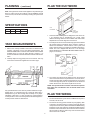
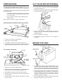
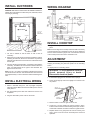
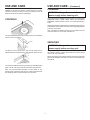
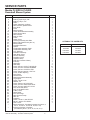
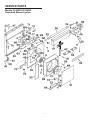
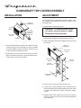
MODELS PL30DD & PL36DD
DOWNDRAFT BLOWER SYSTEM
READ AND SAVE THESE INSTRUCTIONS
! INTENDED FOR DOMESTIC COOKING ONLY !
WARNING
WARNING
TO REDUCE THE RISK OF FIRE, ELECTRIC SHOCK, OR
INJURY TO PERSONS, OBSERVE THE FOLLOWING:
1. Use this unit only in the manner intended by the manufacturer.
If you have questions, contact the manufacturer at the address
or telephone number in the warranty.
2. Before servicing or cleaning unit, switch power off at service
panel and lock the service disconnecting means to prevent
power from being switched on accidentally. When the service
disconnecting means cannot be locked, securely fasten a
prominent warning device, such as a tag, to the service panel.
3. Installation work and electrical wiring must be done by a
qualified person(s) in accordance with all applicable codes
and standards, including fire-rated construction codes and
standards.
4. Sufficient air is needed for proper combustion and exhausting
of gases through the flue (chimney) of fuel burning equipment
to prevent backdrafting. Follow the heating equipment
manufacturer’s guideline and safety standards such as those
published by the National Fire Protection Association (NFPA),
and the American Society for Heating, Refrigeration and Air
Conditioning Engineers (ASHRAE), and the local code authorities.
5. When cutting or drilling into wall or ceiling, do not damage
electrical wiring and other hidden utilities.
6. Do not use this range hood with an additional speed control
device.
7. Ducted fans must always be vented to the outdoors.
8. To reduce the risk of fire, use only metal ductwork.
9. Do not install this product with the activating switch directly
behind a burner or element. Minimum distance between the
switch and the edge of the burner should be 4 inches.
10. Loose-fitting or hanging clothing should never be worn when
operating this appliance. They may be ignited by burners/
elements on cooktop.
11. Children should not be left alone or unattended in the area
where this appliance is in use.
12. When flaming foods, turn the blower OFF. An operating blower
may spread the flames.
13. This unit must be grounded.
TO REDUCE THE RISK OF A RANGE TOP GREASE FIRE:
1. Never leave surface units unattended at high settings. Boilovers
cause smoking and greasy spillovers that may ignite. Heat
oils slowly on low or medium settings.
2. Always turn hood ON when cooking at high heat or when
cooking flaming foods.
3. Clean ventilating fans frequently. Grease should not be allowed
to accumulate on fan or filter.
4. Use proper pan size. Always use cookware appropriate for
the size of the surface element.
TO REDUCE THE RISK OF INJURY TO PERSONS IN THE
EVENT OF A RANGE TOP GREASE FIRE, OBSERVE THE
FOLLOWINGa:
1. SMOTHER FLAMES with a close-fitting lid, cookie sheet,
or metal tray, then turn off the burner. BE CAREFUL TO
PREVENT BURNS. If the flames do not go out immedi
ately, EVACUATE AND CALL THE FIRE DEPARTMENT.
2. NEVER PICK UP A FLAMING PAN - You may be burned.
3. DO NOT USE WATER, including wet dishcloths or towels
- a violent steam explosion will result.
4. Use an extinguisher ONLY if:
A. You know you have a Class ABC extinguisher, and you
already know how to operate it.
B. The fire is small and contained in the area where it
started.
C. The fire department is being called.
D. You can fight the fire with your back to an exit.
a Based on “Kitchen Firesafety Tips” published by NFPA.
CAUTION !
1. For general ventilating use only. Do not use to exhaust
hazardous or explosive materials and vapors.
2. To avoid motor bearing damage and noisy and/or unbalanced
impellers, keep drywall spray, construction dust, etc. off power
unit.
3. Clean filters and grease-laden surfaces frequently.
4. Do not repair or replace any part of this appliance unless
specifically recommended in this manual. All other servicing
should be done by a qualified technician.
5. Please read specification label on product for further information and requirements.
PLANNING
This downdraft blower system is
designed to be used to exhaust
airborne contaminants when
cooking with a variety of gas or
electric cooktops. It can be
mounted in island, peninsula, or
conventional wall locations.
This unit can be easily installed
following these basic steps:
•
Cut out the countertop
opening.
•
Mount the unit in the
cabinet.
•
Connect the ductwork
and electrical.
•
Install the cooktop.
TYPICAL INSTALLATION
CHIMNEY TOP
COUNTER
TOP
COOK TOP
GEAR
MOTOR
COVER
AIR
VENT
BLOWER
BOX
120 VAC
GROUNDED
OUTLET
3-1/4" X 10"
DUCT CONNECTOR
INSTALLER: Save this manual for Electrical Inspector and Homeowner to use.
HOMEOWNER: Use and Care Information on Page 5.
PLANNING - (continued)
PLAN THE DUCTWORK
Note: The high level of air flow of this appliance may affect the gas
flame on some types of gas cooktops. This is NORMAL and will
cause no harm, but can be corrected by lowering the speed of the
blower.
RIGHT
DISCHARGE
SPECIFICATIONS
VOLTS AMPS
120
4.0
LEFT
DISCHARGE
CFM
DUCT
500 3-1/4 X 10
DOWN
DISCHARGE
(as shipped)
1. This downdraft blower system is designed for use with 3-1/4"
x 10" ductwork (can be transitioned to 6" round). Three
different discharge directions are available with side-to-side
adjustment for accurate alignment of ductwork.
2. For best performance: Choose the ducting option which allows
the shortest length of ductwork and a minimum number of
elbows and transitions. Check location of floor joists, wall
studs, electrical wiring or plumbing for possible interference.
NOTE: The unit is shipped with the 3-1/4" x 10" discharge
facing DOWN. See “CHANGING BLOWER DIRECTION” on
page 3, if necessary.
TAKE MEASUREMENTS
1. Refer to the cooktop installation instructions for dimensions of
cooktop, countertop cut-out, and cabinet requirements. The
Model PL30DD will fit in most 30" wide cabinets and the Model
PL36DD will fit in most 36" wide cabinets. However, it is
recommended that oversized cabinets be used for easier installation.
3-1/4" X 10"
TO 6" RD.
TRANSITION
6" ROUND
ELBOW
2. Cooktop depth can vary greatly from one to another. This may
cause the fit of these two appliances to be rather tight.
EQUALS 6 FT. OF
STRAIGHT DUCT
EQUALS 2
FT. OF
STRAIGHT DUCT
3-1/4" X 10"
90O ELBOW
EQUALS 8
FT. OF
STRAIGHT DUCT
3. The system will operate most efficiently when the ductwork
does not exceed 40 feet of equivalent duct. The chart, above,
shows equivalent feet of elbows and transitions. The number
of feet of straight duct plus the equivalent feet of transitions
and/or elbows to be used should equal 40 feet or less.
NOTE: The equivalent feet of various roof and wall caps has
been taken into consideration. Do not include them in this
calculation.
Pay special attention to the areas of potential interference highlighted above. A countertop with (A) a raised lip and/or (B) a
backsplash may not allow enough flat countertop for a proper
installation. Note that 2" of flat countertop is required behind
cooktop and that 1-3/4" is necessary between the back edge of the
cooktop and the inside of cabinet back.
PLAN THE WIRING
1. The downdraft blower system draws 4 AMPS and requires a
120 VAC, 60 Hz circuit.
2. The unit has a 2 ft. long power cord with a 3-pronged plug. Plan
to provide a grounded outlet in a location which will allow the
unit’s power cord to reach. (Note: If the Model PL30DD is being
installed in a 30" wide cabinet or the Model PL36DD is being
installed in a 36" wide cabinet, the outlet cannot be located on
the back wall of cabinet.) Outlet may also be wall-mounted,
with access hole in cabinet.
2
PREPARATION
CUT COUNTERTOP OPENING
CHANGING BLOWER DISCHARGE (Optional)
1. Lay out and cut the cooktop cut-out far enough FORWARD so
downdraft will fit behind it.
The blower is shipped with its discharge facing DOWN. Follow
these steps ONLY if:
2. Set cooktop in place and slide it as far forward as possible.
Center and square it with edges of countertop.
•
the position of the blower discharge needs to be moved
so ductwork does not interfere with floor joists, plumb
ing or wiring below.
•
it is necessary to rotate the blower discharge to the
RIGHT or LEFT.
Place the unit on its back on a table or work surface.
DOWN DISCHARGE - MOVING BLOWER LEFT OR RIGHT
BLOWER
NUTS
SHEET
METAL
SCREW
CLAMP
CHANNEL
3. Place the plastic template against the back flange of the
cooktop and center it. Trace around template to mark the
downdraft opening.
4. Remove cooktop from countertop.
5. Cut downdraft opening. Be careful not to chip edges of
countertop.
BOTTOM
FLANGE
1. Loosen the 4 nuts and 2 clamp channels.
2. Slide blower to desired position.
3. Use supplied cover plate to close open space (if any).
MOUNT THE UNIT
4. Tighten wing nuts to secure top of blower and use sheet metal
screws through bottom flange to secure bottom of blower.
MOUNTING SCREWS
LEVELING BRACKET FLANGE FACING OUT
LEFT OR RIGHT DISCHARGE
BLOWER
NUT
CLAMP
CHANNEL
MOTOR
PLUG
LEVELING BRACKET FLANGE FACING IN
SHEET
METAL
SCREW
COVER PLATE
1. Set downdraft into opening. Extend leveling brackets to floor
of cabinet so downdraft sits straight. (Note: Leveling brackets
can be removed and re-attached in other positions. Bottom
flange may have to face inward in tight cabinet installations.)
1. Remove the 4 nuts and 2 clamp channels.
2. Carefully lift blower and disconnect motor plug if necessary.
Reposition blower and RECONNECT MOTOR PLUG.
4. Replace clamp channels and use nuts to secure the blower in
its new position.
2. Secure the downdraft to the countertop as follows: Hold the
downdraft against the back of countertop cut-out and tightening the 2 mounting screws (one on each end of unit) on
underside of countertop. Use a wood shim between screw and
underside of granite countertops.
5. Use sheet metal screws through bottom flange to secure
bottom of blower.
3. Screw leveling brackets to bottom of cabinet. Tighten screws
holding leveling bracket to unit on each side.
3. Use supplied cover plate to close open space (if any).
3
INSTALL DUCTWORK
WIRING DIAGRAM
CAUTION - BEFORE CUTTING HOLE IN CABINET FOR DUCTWORK: Check for interference with floor joists, wall studs, electrical wiring or plumbing.
BLOWER
➡
SCREWS
➡
3-1/4" X 10"
TO 6" RD.
TRANSITION
COLLAR
6" RD.
ELBOW &
DUCTWORK
INSTALL COOKTOP
1. Align the cooktop with the downdraft and fasten cooktop in
place.
Note: Accurate alignment of cooktop and downdraft is necessary
to ensure that there is no interference when air vent is raised and
lowered. There should be a gap of 1/32"-1/16" between the back
of the cooktop and the front of the downdraft cover.
1. Cut hole in cabinet as well as holes in wall or floor as
necessary.
2. Mount the roof or wall cap and work back towards the cabinet,
attaching all ductwork, elbows and transitions as previously
planned. Tape all ductwork connections to make them secure
and air tight.
ADJUSTMENT
The downdraft is factory-adjusted for proper operation. However,
shipping and handling may affect the position of the activating
switch.
3. Connect ductwork (and transition, if required) to downdraft. If
necessary, LOOSEN nuts and screws that hold the blower in
place, and slide blower left or right to meet ductwork. Retighten screws and nuts.
To adjust position of activating switch:
WARNING: To avoid possible electrical
shock, personal injury or death Disconnect electrical power.
Note: A 3-1/4" x 10" collar is provided for installers who prefer to
rivet the ductwork to the unit. This will allow blower to be removed
and replaced easily in service situations without disturbing ductwork.
1. If downdraft is plugged into electrical outlet, unplug it.
2. Lift air vent straight up and cock it slightly so it remains in the
UP position.
INSTALL ELECTRICAL WIRING
1. Mount a standard wiring box, with 3-pronged receptacle,
inside the cabinet. Make sure the downdraft’s power cord can
easily reach it.
SWITCH
MEMBRANE
2. Run appropriate power cable into cabinet and connect it to
receptacle.
SCREWS
3. Plug the downdraft’s power cord into the outlet.
SWITCH
BRACKET
SWITCH
COVER
3. Remove switch cover from right end of air vent.
4. Loosen the 2 screws holding the switch bracket in place.
Position switch bracket so that activating switch just comes in
contact with underside of switch membrane. Tighten screws.
4
5. Replace switch cover, gently lower air vent into chimney, and
plug in power cord. Re-connect electrical power and check
operation.
USE AND CARE
USE AND CARE - (Continued)
Always turn the downdraft blower on before you begin cooking to
establish an air flow in the kitchen. Let the blower run for a few
minutes to clean the air after you turn the cooktop off. This will
keep the whole kitchen cleaner and brighter.
CLEANING
WARNING: Always disconnect electric
power supply before cleaning unit.
Use a mild detergent suitable for painted surfaces. DO NOT USE
ABRASIVE CLOTH, STEEL WOOL PADS, OR SCOURING
POWDERS. Vacuum blower to clean. Do not immerse blower in
water.
CONTROLS
Wash the 2 aluminum grease filters in a mild detergent solution or
a dishwasher. Remove them from the air vent by grasping the tab
at the top of each filter.
Note: The filters are different sizes. Be sure to replace them as
removed, (wider one on the left), with tabs UP.
Turn the downdraft blower ON by pressing down on the activating
switch. The air vent will rise.
SERVICING
KNOB
WARNING: Always disconnect electric
power supply before servicing unit.
The blower can be turned ON or OFF and its speed can be
adjusted with the recessed knob on the right side of the air vent.
It may be necessary to remove the downdraft blower system from
the cabinet in order to service components such as the blower
motor or air vent mechanism.
Disconnect power to the cooktop and remove it first. Reverse the
steps under “MOUNT THE UNIT” to remove the downdraft from
the cabinet.
Turn the downdraft blower OFF by pressing the activating switch
again. The air vent will go down and the blower will shut OFF.
Note: For most convenient operation, set the blower to your
favorite speed. The blower will come on to this speed whenever
the activating switch is pressed and the air vent rises.
5
SERVICE PARTS
Models PL30DD & PL36DD
Downdraft Blower System
KEY NO.
1
2
3
4
5
6
7
8
9
10
11
12
16
17
18
19
20
21
22
23
24
25
26
28
29
30
31
32
33
45
46
47
49
50
51
52
53
54
55
56
57
58
59
60
61
62
64
65
66
67
68
70
71
73
74
75
84
**
**
DESCRIPTION
Bushing, 7/8"
Bushing, Split Heyco, 5/8"
Bushing, Heyco, 1/2"
Roller
Switch Assembly, Up/Down
Wire Harness, Speed Control
Nut, 3/8-32
Knob
Motor Insolator
Lower Switch Bracket Assembly
Green Ground Wire
Wire Harness
Back-up Plate
Crank
Switch Cover
Chimney Assembly with Slide
Motor (with Capacitor-Key No. 73)
Blower Wheel
Scroll Box Extension
Spacer
Top Bracket Assembly, Right
Top Bracket Assembly, Left
Top, Stainless
Scroll Box Assembly
Gear Motor Cover
Air Box Assembly
Scroll Box Cover
Capacitor Strap
Filter Kit (contains 2 filters)
End Cap
Gearmotor
Slide Strip
Screw, #8-18 x .375 SLT HX WS HD
Screw, #10-32 x .500 HX WS BDRH
Screw, #8-18 x .375 SR PH TRH
Screw, #8-18 x .500 No. 5 PH Trim
Cover, Air Box Opening
Nut, #10-24
Air Box Cover
Gearmotor Bracket Assembly
Leg Support
Screw, 1/4-20 x 5/16
Washer, 1/4
Screw, #8-32 x 1/2 PH HD MS
Screw, #10-24 x 3/8 SH WH LOCK
Screw, #10-24 x 3/8 PH FL HD LD
Nut, 10-24 HEX KEPS
Nut, 1/4-20 WHIZ LOCK
U-Bolt, 10-24
Strain Relief
Nut, Hex Flange
Wire Channel Clamp
Wire Tie
Capacitor
Screw, 1/4-20 x 1.250 HEX HD
#8-18 x .250 PH TR HD BPT
Seal - Foam
Blower Assembly, Complete (Includes Key Nos.2, 9,
20, 21, 22, 28, 31, 32, 49, 58, 64, 65, & 73)
Chimney Assembly, Complete
(Includes Key Nos. 5, 8, 19, 45, 51, 52, & 71)
*Standard Hardware - May be purchased locally.
**Service Assembly - Contains numerous parts.
6
QTY.
1
1
1
1
1
1
1
1
3
1
1
1
1
1
1
1
1
1
1
3
1
1
1
1
1
1
1
1
1
1
1
4
19
2
6
2
1
4
1
1
2
5
2
4
1
1
7
3
1
1
1
2
3
1
2
2
1
OPTIONAL TOP COVER KITS
MODEL NO.
DESCRIPTION
HT2730B
30" Black
HT2736B
36" Black
HT2730W
30" White
HT2736W
36" White
SERVICE PARTS
Models PL30DD & PL36DD
Downdraft Blower System
75
84
7
Major Appliance Warranty Information
Your appliance is covered by a one year limited warranty. For one year from your original date of purchase,
Electrolux will pay all costs for repairing or replacing any parts of this appliance that prove to be defective
in materials or workmanship when such appliance is installed, used, and maintained in accordance with the
provided instructions.
Exclusions
This warranty does not cover the following:
1.
Products with original serial numbers that have been removed, altered or cannot be readily determined.
2.
Product that has been transferred from its original owner to another party or removed outside the USA or
Canada.
3.
Rust on the interior or exterior of the unit.
4.
Products purchased "as-is" are not covered by this warranty.
5.
Food loss due to any refrigerator or freezer failures.
6.
Products used in a commercial setting.
7.
Service calls which do not involve malfunction or defects in materials or workmanship, or for appliances
not in ordinary household use or used other than in accordance with the provided instructions.
8.
Service calls to correct the installation of your appliance or to instruct you how to use your appliance.
9.
Expenses for making the appliance accessible for servicing, such as removal of trim, cupboards, shelves, etc.,
which are not a part of the appliance when it is shipped from the factory.
10. Service calls to repair or replace appliance light bulbs, air filters, water filters, other consumables, or knobs,
handles, or other cosmetic parts.
11. Surcharges including, but not limited to, any after hour, weekend, or holiday service calls, tolls, ferry trip
charges, or mileage expense for service calls to remote areas, including the state of Alaska.
12. Damages to the finish of appliance or home incurred during installation, including but not limited to floors,
cabinets, walls, etc.
13. Damages caused by: services performed by unauthorized service companies; use of parts other than genuine
Electrolux parts or parts obtained from persons other than authorized service companies; or external causes
such as abuse, misuse, inadequate power supply, accidents, fires, or acts of God.
DISCLAIMER OF IMPLIED WARRANTIES; LIMITATION OF REMEDIES
CUSTOMER'S SOLE AND EXCLUSIVE REMEDY UNDER THIS LIMITED WARRANTY SHALL BE PRODUCT
REPAIR OR REPLACEMENT AS PROVIDED HEREIN. CLAIMS BASED ON IMPLIED WARRANTIES, INCLUDING
WARRANTIES OF MERCHANTABILITY OR FITNESS FOR A PARTICULAR PURPOSE, ARE LIMITED TO ONE
YEAR OR THE SHORTEST PERIOD ALLOWED BY LAW, BUT NOT LESS THAN ONE YEAR. ELECTROLUX
SHALL NOT BE LIABLE FOR CONSEQUENTIAL OR INCIDENTAL DAMAGES SUCH AS PROPERTY DAMAGE
AND INCIDENTAL EXPENSES RESULTING FROM ANY BREACH OF THIS WRITTEN LIMITED WARRANTY
OR ANY IMPLIED WARRANTY. SOME STATES AND PROVINCES DO NOT ALLOW THE EXCLUSION OR
LIMITATION OF INCIDENTAL OR CONSEQUENTIAL DAMAGES, OR LIMITATIONS ON THE DURATION OF
IMPLIED WARRANTIES, SO THESE LIMITATIONS OR EXCLUSIONS MAY NOT APPLY TO YOU. THIS
WRITTEN WARRANTY GIVES YOU SPECIFIC LEGAL RIGHTS. YOU MAY ALSO HAVE OTHER RIGHTS
THAT VARY FROM STATE TO STATE.
If You Need
Service
Keep your receipt, delivery slip, or some other appropriate payment record to establish the warranty period
should service be required. If service is performed, it is in your best interest to obtain and keep all receipts.
Service under this warranty must be obtained by contacting Electrolux at the addresses or phone numbers below.
This warranty only applies in the USA and Canada. In the USA, your appliance is warranted by Electrolux Major Appliances North
America, a division of Electrolux Home Products, Inc. In Canada, your appliance is warranted by Electrolux Canada Corp. Electrolux
authorizes no person to change or add to any obligations under this warranty. Obligations for service and parts under this warranty
must be performed by Electrolux or an authorized service company. Product features or specifications as described or illustrated
are subject to change without notice.
USA
1.800.944.9044
Electrolux Major Appliances
North America
P.O. Box 212378
Augusta, GA 30907
Canada
1.800.668.4606
Electrolux Canada Corp.
5855 Terry Fox Way
Mississauga, Ontario, Canada
L5V 3E4
99043820A
DOWNDRAFT TOP COVER ASSEMBLY
INSTALLATION
ADJUSTMENT
SWITCH
MEMBRANE
The downdraft is factory-adjusted for proper operation. However, shipping and handling may affect the position of the
activating switch.
To adjust position of activating switch:
TOP
COVER
LEG
2 MOUNTING
SCREWS
EACH SIDE
ACTIVATING
SWITCH
CHIMNEY
WARNING: To avoid possible electrical shock, personal injury or death Disconnect electrical power.
1. If downdraft is plugged into electrical outlet, unplug it.
2. Lift air vent straight up and cock it slightly so it remains in the
UP position.
SWITCH
MEMBRANE
1. Press activating switch to raise chimney. NOTE: If electrical power supply is not connected, lift chimney manually
and cock it slightly to keep it in position. Remove four (4)
screws and remove existing top cover.
ACTIVATING
SWITCH
2. Slide legs on top cover into ends of chimney as shown.
Make sure switch membrane is above activating switch.
Fasten with four (4) screws provided.
ADJUSTING
SCREW
SWITCH
COVER
SWITCH
BRACKET
ADJUSTING
SCREW
3. Remove switch cover from right end of air vent.
4. Loosen the 2 screws holding the switch bracket in place.
Position switch bracket so that activating switch just comes
in contact with underside of switch membrane. Tighten
screws.
5. Replace switch cover, gently lower air vent into chimney,
and plug in power cord. Re-connect electrical power and
check operation.
Major Appliance Warranty Information
Your appliance is covered by a one year limited warranty. For one year from your original date of purchase,
Electrolux will pay all costs for repairing or replacing any parts of this appliance that prove to be defective
in materials or workmanship when such appliance is installed, used, and maintained in accordance with the
provided instructions.
Exclusions
This warranty does not cover the following:
1.
Products with original serial numbers that have been removed, altered or cannot be readily determined.
2.
Product that has been transferred from its original owner to another party or removed outside the USA or
Canada.
3.
Rust on the interior or exterior of the unit.
4.
Products purchased "as-is" are not covered by this warranty.
5.
Food loss due to any refrigerator or freezer failures.
6.
Products used in a commercial setting.
7.
Service calls which do not involve malfunction or defects in materials or workmanship, or for appliances
not in ordinary household use or used other than in accordance with the provided instructions.
8.
Service calls to correct the installation of your appliance or to instruct you how to use your appliance.
9.
Expenses for making the appliance accessible for servicing, such as removal of trim, cupboards, shelves, etc.,
which are not a part of the appliance when it is shipped from the factory.
10. Service calls to repair or replace appliance light bulbs, air filters, water filters, other consumables, or knobs,
handles, or other cosmetic parts.
11. Surcharges including, but not limited to, any after hour, weekend, or holiday service calls, tolls, ferry trip
charges, or mileage expense for service calls to remote areas, including the state of Alaska.
12. Damages to the finish of appliance or home incurred during installation, including but not limited to floors,
cabinets, walls, etc.
13. Damages caused by: services performed by unauthorized service companies; use of parts other than genuine
Electrolux parts or parts obtained from persons other than authorized service companies; or external causes
such as abuse, misuse, inadequate power supply, accidents, fires, or acts of God.
DISCLAIMER OF IMPLIED WARRANTIES; LIMITATION OF REMEDIES
CUSTOMER'S SOLE AND EXCLUSIVE REMEDY UNDER THIS LIMITED WARRANTY SHALL BE PRODUCT
REPAIR OR REPLACEMENT AS PROVIDED HEREIN. CLAIMS BASED ON IMPLIED WARRANTIES, INCLUDING
WARRANTIES OF MERCHANTABILITY OR FITNESS FOR A PARTICULAR PURPOSE, ARE LIMITED TO ONE
YEAR OR THE SHORTEST PERIOD ALLOWED BY LAW, BUT NOT LESS THAN ONE YEAR. ELECTROLUX
SHALL NOT BE LIABLE FOR CONSEQUENTIAL OR INCIDENTAL DAMAGES SUCH AS PROPERTY DAMAGE
AND INCIDENTAL EXPENSES RESULTING FROM ANY BREACH OF THIS WRITTEN LIMITED WARRANTY
OR ANY IMPLIED WARRANTY. SOME STATES AND PROVINCES DO NOT ALLOW THE EXCLUSION OR
LIMITATION OF INCIDENTAL OR CONSEQUENTIAL DAMAGES, OR LIMITATIONS ON THE DURATION OF
IMPLIED WARRANTIES, SO THESE LIMITATIONS OR EXCLUSIONS MAY NOT APPLY TO YOU. THIS
WRITTEN WARRANTY GIVES YOU SPECIFIC LEGAL RIGHTS. YOU MAY ALSO HAVE OTHER RIGHTS
THAT VARY FROM STATE TO STATE.
If You Need
Service
Keep your receipt, delivery slip, or some other appropriate payment record to establish the warranty period
should service be required. If service is performed, it is in your best interest to obtain and keep all receipts.
Service under this warranty must be obtained by contacting Electrolux at the addresses or phone numbers below.
This warranty only applies in the USA and Canada. In the USA, your appliance is warranted by Electrolux Major Appliances North
America, a division of Electrolux Home Products, Inc. In Canada, your appliance is warranted by Electrolux Canada Corp. Electrolux
authorizes no person to change or add to any obligations under this warranty. Obligations for service and parts under this warranty
must be performed by Electrolux or an authorized service company. Product features or specifications as described or illustrated
are subject to change without notice.
USA
1.800.944.9044
Electrolux Major Appliances
North America
P.O. Box 212378
Augusta, GA 30907
Canada
1.800.668.4606
Electrolux Canada Corp.
5855 Terry Fox Way
Mississauga, Ontario, Canada
L5V 3E4
99043821A