1
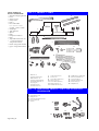
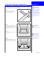
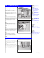
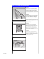
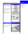
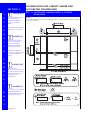
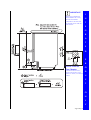
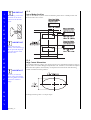
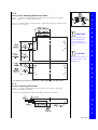
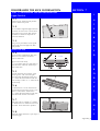
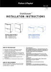
USA DD602 (Prefinished) Part No. 599065/D DD602I (Integrated) Models DD602 DD602I Table of Contents Section Section Section Section Section Section Section Section Page DD_01 1 General Information 1.1 1.2 1.3 1.4 1.5 1.6 Preparation Product Specifications & Cavity Dimensions Options for Installing Multiple Products Electrical, Plumbing & Drainage Information Product Parts Additional Product Parts for Integrated DishDrawer 2 Foot Slide Retainer Information 2.1 2.2 Assembling the Foot Slide Retainer Securing the Foot Slide Retainer 3 Fitting the DishDrawer 3.1 3.2 3.3 3.4 3.5 Connecting the Services Flexible Extrusion Attachment for 24 by 341/2 (610mm x 876mm) Cavity Adjusting the Feet Fitting the Endplate to the Chassis (Optional) Securing the DishDrawer 4 Prefinished Toe Kick Installation 4.1 4.2 4.3 4.4 Setting the Upper Toe Kick Height Trimming the Lower Toe Kick Trimming the Toe Kick Pins Adjusting the Upper Toe Kick 5 5.1 6 6.1 6.2 6.3 6.4 6.5 7 7.1 8 8.1 8.2 Information for Cabinet Maker for Integrated DishDrawer Integrated Drawer Front & Toe Kick Dimensions Integrated Drawer Front Installation Changing the Integrated Badge Enclosure Disassembling the Integrated Badge Assembling the Integrated Badge Fitting the Badge, Handle & Mounting Panel to the Drawer Front Fitting the Drawer Front Panels to the DishDrawer DishDrawer Toe Kick Information Integrated Toe Kick Installation Final Checks Installation Wet Test Troubleshooting SECTION 1 GENERAL INFORMATION STEP 1.1 PREPARATION NOTE TO THE INSTALLER n Be sure to leave these instructions with the Customer. n Ensure this appliance is properly grounded. NOTE TO THE CONSUMER n Keep these Installation Instructions with your Use & Care Manual for future reference. IMPORTANT n Read these Instructions completely and carefully. n Observe all governing Codes and Ordinances. WARNING n These Instructions are intended as a guide only. n It is the responsibility of the plumber and electrician to ensure that each installation complies with all Codes and Ordinances. n Installation of this DishDrawer requires basic mechanical and electrical skills. n The installer is responsible for the DishDrawer installation. Improper installation is not covered under the Express Warranty Form. IMPORTANT n At the completion of the DishDrawer installation, the Installer must perform Final Checks as per Section 8 of these Installation Instructions. n Ensure the DishDrawer enclosure is prepared for installation. n Remove all packaging and materials supplied with the DishDrawer. n If you have any questions concerning the installation of this DishDrawer, contact: Fisher & Paykel Customer Care Centre TOLL FREE 1-888-9-FNP USA TOLL FREE 1-888-9-36 7 872 Fax (949) 790 8911 WWW.FISHERPAYKEL.COM 27 Hubble Irvine CA 92618 USA WARNING Before installing the DishDrawer, remove the house fuse or open the circuit breaker. Ensure all water connections are turned OFF. WARNING The DishDrawer MUST be installed to allow for future removal from the enclosure if service is required. STEP 1.2 PRODUCT SPECIFICATIONS & CAVITY DIMENSIONS Electrical Drying Water Connection Water Pressure 110-120 VAC (Water pressure below 7 p.s.i. 3 pin socket outlet (50 kpa) may require the electronics Residual Heat to be re-programmed by a Service & Fan Assisted Person at the time of installation) Recommended Hot 140°F Max. (60°C) Maximum 139 p.s.i. (960 kpa) Minimum 4.3 p.s.i. (30 kpa) Page DD_02 IMPORTANT STEP 1.3 OPTIONS FOR INSTALLING MULTIPLE PRODUCTS Where the DishDrawer is installed under a counter top, it is recommended that bare wood surrounding the DishDrawer is sealed with an oil based paint or polyurethane to prevent possible steam damage. STEP 1.4 ELECTRICAL, PLUMBING & DRAINAGE INFORMATION IMPORTANT ELECTRICAL Ensure the cavity sides Care should be exercised when the appliance is installed or removed, to are plumb (vertical) as reduce the likelihood of damage to the power supply cord. this will assist with leveling the DishDrawer. If the power supply cord is damaged, it must be replaced by the Manufacturer, its Service Agent or a similarly qualified person, in order to avoid a hazard. IMPORTANT Ensure the Services Hole is as close as possible to the rear lower corner of the cabinetry. The hole can be located on either side depending on the location of the services. IMPORTANT On corner installations, ensure that there is a gap of 2" (50mm) minimum between the adjacent cabinetry and sides of drawers. The power supply receptacle for the appliance should be installed in a cabinet or on a wall adjacent to the under counter space in which the appliance is to be installed. The power supply receptacle should be positioned between 6" and 18" (150mm and 450mm) from the cabinet opening of the DishDrawer. GROUNDING INSTRUCTIONS This appliance must be grounded. In the event of malfunction or breakdown, grounding will reduce the risk of electric shock by providing a path of least resistance for electric current. This appliance is equipped with a cord having an equipment-grounding conductor and a grounding plug. The plug must be plugged into an appropriate outlet that is installed and grounded in accordance with all local Codes & Ordinances. PLUMBING - WATER SUPPLY a) b) c) d) e) Page DD_03 The water connection is to be made to a hot water supply only. Ensure the water temperature is not greater than 140°F (60°C). A readily accessible shut off valve must be installed in the supply pipe. The water supply pressure is to be between 4.3 p.s.i. minimum and 139 p.s.i. maximum. The inlet supply hose must be connected to the water supply using a 3/8" compression type water supply fitting. Ensure sealing washer supplied with connection hose is fitted. PLUMBING - DRAINAGE OPTIONS Option 1 WARNING Improper connection of the equipment-grounding conductor can result in a risk of electric shock. Check with a qualified electrician or service representative if you are in doubt as to whether the appliance is properly grounded. Do not modify the plug provided with the appliance - if it will not fit the outlet, have a proper outlet installed by a qualified electrician. Option 2 WARNING The Drain Hose Support must be at least 30" (750mm) above the floor to prevent siphoning of the water during the wash cycle. It is recommended that the Drain Hose Support is secured in place using the screw tab. Ensure that the drain hoses are fully extended. Option 3 Note: Prefinished Model is shown. There is no variation in plumbing between Prefinished products and Integrated products. Options 1 and 2 are the most preferred options. Page DD_04 TOOLS NEEDED TO INSTALL DISHDRAWER Wooden Chopping Board Level Safety Glasses Utility Knife Pencil Drill & Drill Bits (3/32", 9/16" & 11/32") or (2.5mm, 12mm, 14mm) Sandpaper Tape Measure Square Ruler Phillips Screwdriver Pliers Adjustable Wrenches (x2) 7/32" (6mm) Allen Key (Integrated Models) Router (Integrated Models) Jigsaw (Integrated Models) STEP 1.5 PRODUCT PARTS 1. 2. 4. 3. 6. 5. 7. 8. 9. 10. 12. 11. 13. 16. 14. 18. 15. 1. 2. 3. 4. 5. 6. Retainer (1) (Channel Transverse) Slide Runners (2) (Channel Longitudinals) Foot Slide Template (1) Clip Pegs (2) Toe Kick Pins (2) Toe Kick Brace (1) 17. 7. 8. 9. 10. 11. 12. 13. 19. Lower Toe Kick (1) Screws (11) Drain Hose Support (1) Wire Clips (2) Drain Hose Joiner (1) Edge Protector (1) Flexible Extrusion (3) 14. 15. 16. 17. 18. 19. Solderless Lug & Washer Inlet Hose Washer (1) Transit Packer (1) Masonry Anchors (2) Hose Clamp (1) Endplates (2) STEP 1.6 ADDITIONAL PRODUCT PARTS FOR INTEGRATED DISHDRAWER 20. 21. 22. 23. 24. Small Screws (14) Badge Kit (2) Mounting Bracket Nuts (8) Door Screws (8) Seal (2) 20. 21. 23. 22. Page DD_05 24. FOOT SLIDE RETAINER INFORMATION SECTION 2 STEP 2.1 ASSEMBLING THE FOOT SLIDE RETAINER The Foot Slide Retainer is made up with one Retainer and two Slide Runners. The Toe Kick Brace is NOT used in the Foot Slide Retainer. 2.1.1 Bend the tabs at both ends of the Retainer so they fit the width of the cavity for the DishDrawer. IMPORTANT It is important that the Foot Slide Retainer is correctly installed. It guides the feet back and holds the rear of the DishDrawer down to prevent it rocking forward when the drawers are opened. It also aligns the product to the cavity front. 2.1.2 Assemble the Foot Slide Retainer by forming three sides of a square with the Retainer and Slide Runners as shown, ensuring that they fit together. Place in the cavity. WARNING Be careful of sharp edges. 2.1.3 Using the front of the cavity, create a center point. IMPORTANT 2.1.4 Place the Template in the cavity ensuring that the template is sitting flat and lines up with your center point. If there is a drop down in the cavity, you may have to build the cavity up level with the finished floor. Page DD_06 IMPORTANT 2.1.5 For Integrated product with door thickness other than 3/4 (18mm), the Foot Slide position must be adjusted forward or back to allow for this difference. 2.1.6 Position the Foot Slide Retainer within the cutout areas of the Template. The Template should be placed in the cavity until the wings just touch the existing cabinetry. This ensures the front of the DishDrawer will be flush with the existing cabinetry. ü Correct û Incorrect STEP 2.2 SECURING THE FOOT SLIDE RETAINER IMPORTANT Check for any protrusions that may interfere with the DishDrawer sliding back into the cavity and allow for these. There are two options available for securing the Foot Slide Retainer. Either option is adequate for securing the DishDrawer. Using both options together is optimum. 2.2.1 The first and preferred option is to screw the Retainer to the floor. The tabs can be broken off at the perforations, if they are not used. 2.2.2 IMPORTANT The Foot Slide Retainer must be adequately secured to prevent movement. The second option is to screw the Retainer to the cabinet sides. 2.3.3 Masonry Anchors are supplied with the accessories to replace the long screws if attaching the Foot Slide Retainer to concrete flooring. Masonry Anchors should not be used if there is any chance of damaging underfloor heating. Page DD_07 FITTING THE DISHDRAWER SECTION 3 STEP 3.1 CONNECTING THE SERVICES 3.1.1 Feed the Power Cord, Inlet Hose and Drain Hoses through the Services Hole. Position the DishDrawer in front of the opening. 3.1.2 Connect the Inlet Hose to the HOT WATER SUPPLY. Ensure sealing washer supplied with the accessories is fitted. Hose coupling must be tightened a further half turn after seal contact. WARNING Ensure the edges of the Services Hole are smooth or covered. (See Step 1.2 Product Specifications & Cavity Dimensions.) If the Services Hole is through a metal partition, the hole must be protected with the Edge Protector provided. 3.1.3 If required, the Drain Hose may be trimmed to a suitable length. 3.1.4 If an air break option is not chosen, then the Drain Hose Support must be used and positioned at least 30" (750mm) above the floor to prevent siphoning of the water during the wash cycle. (See Step 1.4 Electrical, Plumbing & Drainage Information.) 3.1.5 When using a standpipe option, hoses should not extend further than 2 (50mm) down the standpipe in order to prevent siphoning. WARNING DO NOT adjust the length of the Inlet Hose. TIP Turn the water valve ON to check for any leaks, before pushing the DishDrawer back into its cavity. 3.1.6 If required, trim the Drain Hose Joiner to the size which matches the waste tee or air break to be used. There are ribs provided to guide cutting. When using the Drain Hose Joiner, the hoses should be pushed in firmly, 5 clicks. 3.1.7 WARNING Attach the Drain Hose Support to the cabinet joinery to prevent siphoning and keep the drain hoses from kinking. Attach the Drain Hose Joiner to the waste tee(see Step 1.4). Ensure a snug fit, using the hose clamp supplied. The supplied Wire Clips should be installed between the two positioning ribs on the Drain Hose Joiner. Remember to slip the Wire Clips over the Drain Hoses before connecting to the Drain Hose Joiner. Page DD_08 3.1.8 WARNING Ensure there is a power outlet in reach of the supplied flex. If there is not a suitable outlet available then have one installed by a qualified electrician. The Product must not be plugged in at this stage. DO NOT modify the power plug supplied with the DishDrawer or use an extension cord, adaptor plug or multiple outlet box. WARNING If permanently connecting, ensure power is isolated. 3.1.9 Alternatively, the DishDrawer may be permanently connected to flexible conduit. Remove the flex and cable clamp. Fit suitable cable clamp for the conduit and terminate the wiring as shown. Use the solderless lug and washer supplied with the product parts to terminate the ground wire. STEP 3.2 FLEXIBLE EXTRUSION ATTACHMENT FOR 24 BY 341/2 (610mm x 876mm) CAVITY 3.2.1 Flexible Extrusions are supplied to enable the installer to help fill any excess space between the sides and top of the DishDrawer and the cavity. The three lengths of Flexible Extrusion (supplied) should be attached before pushing the DishDrawer into the cavity for final installation. The Extrusions are designed to fit a 24 width by 341/2 high cavity (610mm x 876mm). TIP Wiring, Plumbing and Services should be completed before attaching the flexible extrusion. 3.2.2 Open the drawers, exposing the chassis trim. 3.2.3 Remove backing from adhesive tape on Flexible Extrusion. The larger of the Extrusions is used to fill the gap at the top of the product. Cabinet 3.2.4 Cabinet DishDrawer DishDrawer Apply as per drawings, ensuring the curved edge of the Flexible Extrusion fits around the corner of the chassis trim. 3.2.5 Page DD_09 When checking final fit, ensure the DishDrawer is centered and there are even tolerances between the DishDrawer and cavity. STEP 3.3 ADJUSTING THE FEET 3.3.1 Measure front of product to align to cabinetry as required. Ensure a minimum of 1/8" (2.5mm) clearance to the underside of the counter. The height difference between the front and the back of the DishDrawer must be no more than 1/8" (2.5mm). 3.3.2 To adjust the feet, loosen the locknuts and turn the feet. If the product needs to be adjusted to its lowest setting, the plastic surround will need to be removed by unscrewing and lifting it up and slipping it off the foot. 3.3.3 Tighten the locknuts on the rear feet while ensuring the moulded section of the feet line up parallel to the sides of the product. 3.3.4 Lift the back of the DishDrawer and insert the back feet into the Slide Runners. Slide the DishDrawer partially back, leaving enough room to adjust the front feet. 3.3.5 Further adjustment may be made if necessary. Lock the front feet while ensuring the moulded section of the feet line up parallel to the sides of the product. IMPORTANT The DishDrawer must be levelled so that each corner is at least within 1 /8 (3mm) of level. WARNING The DishDrawer should not support any part of the kitchen cabinets. IMPORTANT Make sure the Inlet and Drain Hoses are not restricted or damaged. TIP Each turn of the foot adjusts by 3/64 (1.25mm). TIP For ease when sliding the feet back, place a little soap on the Slide Runners. STEP 3.4 FITTING THE ENDPLATE TO THE CHASSIS (OPTIONAL) 3.4.1 If the customer sees a need, Endplates may be used to obtain a flush appearance to the side of Toe Kick area of the product. The Endplate is fitted by peeling off the adhesive backing and adhering to the side of the chassis, lining up the front of the Endplate with the Upper Toe Kick. Page DD_10 STEP 3.5 SECURING THE DISHDRAWER 3.5.1 Partially lift the top mounting tabs by inserting a flat screwdriver into the Vee shaped slot. Complete the folding process by bending about the rows of oval slots so that the tab is approximately level and parallel with the underside of the bench. 3.5.2 Lift the DishDrawer and insert the front feet into the Slide Runners. While the machine is still outside the cavity, fold out the tabs on top of the DishDrawer. Push the DishDrawer back until the back feet slide into the rear grooves of the Retainer. Ensure the DishDrawer is as far back as it will go. 3.5.3 Insert the Clip Pegs into the Slide Runners in front of the front feet. Push the Clip Peg back until it locates in the two holes on either side of the Slide Runner. This locks the DishDrawer in place as well as providing the mounting clips for the Lower Toe Kick. 3.5.4 Screw in tabs to underside of bench. Use the two Phillips No. 8 x 5/8 screws supplied to secure the DishDrawer to the bench. This provides optimal product rigidity within the cavity. Page DD_11 PREFINISHED TOE KICK INSTALLATION SECTION 4 STEP 4.1 SETTING THE UPPER TOE KICK HEIGHT 4.1.1 IMPORTANT Remove the Upper Toe Kick by opening the bottom drawer, then holding the Toe Kick at the base, pull outwards to unclip and rotate up. Ensure that the Transit Packer located beneath the upper Toe Kick has been removed. 4.1.2 Ensure the screws are at the highest position, so the Upper Toe Kick will be situated on the DishDrawer as high as it can go. This allows for later adjustment to suit the Lower Toe Kick. 4.1.3 Replace the Upper Toe Kick by feeding the top tabs up through the slots in the tub, then rotate the Toe Kick to clip back and lock home. STEP 4.2 TRIMMING THE LOWER TOE KICK 4.2.1 The Lower Toe Kick sits flush with the floor. Turn the Lower Toe Kick upside down and position at a 90° angle against the already fitted Upper Toe Kick. P U Page DD_12 IMPORTANT Before cutting the Lower Toe Kick, ensure the Toe Kick is positioned on a wooden chopping board to avoid damage to surrounding area. 4.2.2 To establish which groove to trim along, measure the Toe Kick against both sides of the product, allowing a minimum gap of 3/32 (2.5mm) between the Upper and Lower Toe Kicks. Neatly cut through the vertical ribs of the Toe Kick and trim along the full length of the groove. 4.2.3 IMPORTANT Ensure the Toe Kick Pins are positioned on a wooden chopping board to avoid damage to surrounding area. Bend the cut edges apart slightly and carefully cut through from the front. 4.2.4 Sand the edges to remove any rough patches. STEP 4.3 TRIMMING THE TOE KICK PINS 4.3.1 Mark the Toe Kick Pins against the trimmed Lower Toe Kick. NOTE: DO NOT insert the Pins into the Kick before cutting to length. 4.3.2 Place the Toe Kick Pin onto a wooden chopping board and trim the Pin by cutting down the corresponding groove to the trimmed Lower Toe Kick. Cut the outer edges of the Toe Kick Pins from the inside to the outside. Page DD_13 4.3.3 If the height of the Lower Toe Kick is greater than 11/4" (32mm) , insert the Toe Kick Brace in between the two lowest ribs of the Lower Toe Kick. Orientate the Lower Toe Kick so that the arrow points upwards. Toe Kick Brace 4.3.4 Insert the Toe Kick Pins into the Lower Toe Kick. These will hold the Brace in place. STEP 4.4 ADJUSTING THE UPPER TOE KICK 80 9 19 16 6 30 17 7 7 18 8 20 Snap the Lower Toe Kick into the Clip Pegs in the Slide Retainer. 8 4.4.1 4 Upper Toe Kick 1 11 28 12 2 5 13 3 14 29 15 5 6 Measure the gap between the Lower and Upper Toe Kick at the left and right sides. 80 10 4 8 6 6 26 7 7 3 8 9 27 9 5 5 2 Lower Toe Kick 4 25 4 4.4.2 Remove the Upper Toe Kick and using the increments, adjust to allow a 3/32" (2.5mm) gap between the two Toe Kicks. Replace the Upper Toe Kick and check. Page DD_14 SECTION 5 I N T E G R A T E D IMPORTANT Recommended Drawer Front thickness for Integrated products is 5 /8" to 3/4" (16mm to 18mm). Recommended Toe Kick thickness is 3/8" (9mm). IMPORTANT Drawer Front material must be suitable for damp conditions or adequately sealed to withstand moisture. Additional protection can be provided by using a Moisture Resistant Board. P R O D U IMPORTANT Allow for any obstructions at the top of the cavity when allowing for space between the countertop and DishDrawer. C T O N IMPORTANT A 1/4 (6mm) gap must be provided between top and bottom Drawer Front in the position shown. L Y Page DD_15 INFORMATION FOR CABINET MAKER FOR INTEGRATED DISHDRAWER STEP 5.1 INTEGRATED DRAWER FRONT & TOE KICK DIMENSIONS 5.1.1 Use the following diagrams to work out the dimensions for the Integrated Panels for Drawer Fronts and Toe Kicks.. IMPORTANT Check top and bottom measurements of cavity and use the smaller dimension to ensure that the drawer fronts and toe kicks will fit. I N T E G R A T E D P R Drawer Front Air Flow Chamfer Chamfer the back of the Drawer Front Panel at the bottom as shown, to enhance airflow. O D U C T O N L Y Page DD_16 I N T IMPORTANT All marking out should be done on the back surface of the Drawer Front. 5.1.2 Control Badge Position Badge can be located anywhere within the Mounting Zone shown. Handle position will need to be taken into account. E G R A T E D IMPORTANT When mounting the handle, ensure fastenings do not protrude beyond the back surface of the Drawer Front. P 5.1.3 R Badge Cutout Dimensions O from Fisher & Paykel or alternatively a Template can be found on the Mounting Bracket enclosed with the product. D U C Cut out Badge Mounting Hole in the chosen position (see Control Badge Mounting Zone on diagram above). A Control Badge Template (Part No. 526253) is available on request IMPORTANT Accuracy is essential when cutting the Badge Mounting Hole to ensure a neat fit to hold the badge. T O The Badge Mounting Hole is an ellipse shape. N L Y Page DD_17 5.1.4 I Drawer Front Mounting Bracket Nut Holes Using a /32 (8.5mm) diameter drill bit, drill out the four screw holes in each door panel to a depth of 9/16 (14mm). Remove burrs. N At least 5/8 (16mm) of Drawer Front material is required for the Drawer Mounting Nuts (M6 screw in nut - Type E). T 11 E WARNING Use of a depth gauge is recommended when drilling out holes for Drawer Front Mounting Panel. CAUTION Ensure the drill does not damage the face of the Drawer Front. G R A T E D P R O D * These dimensions are important to ensure the 1/4 (6mm) airflow gap is correctly located. U 5.1.5 Toe Kick Mounting Pilot Holes C Using a 3/32 (2.5mm) diameter drill bit, drill out the six screw holes in the Upper Toe Kick to a depth of 1/4(6mm). T Lower Toe Kick Mounting Pilot Holes are drilled at the time of installation. O N L Y Page DD_18 SECTION 6 I N T E G INTEGRATED DRAWER FRONT INSTALLATION STEP 6.1 CHANGING THE INTEGRATED BADGE ENCLOSURE IMPORTANT To avoid electric shocks and damage to electronic components, the integrated badge should be disconnected from the DishDrawer when changing the badge enclosure. R There are several different colored Integrated badges to choose from. They include black, chrome, satin & brass. Two color options are provided with your machine, other options are available from your local Dealer. There are five parts to the Integrated Badge Assembly. They are as follows: 1. Integrated Badge 2. Badge Buttons 3. Light Pipe 4. Electronics Board 5. Badge Cover 6. Wires 5. 3. 1. 4. 2. 6. STEP 6.2 DISASSEMBLING THE INTEGRATED BADGE A 6.2.1 T Remove Badge Cover from the Integrated Badge. At the back of the Integrated Badge, slide the Badge Cover away from the wire terminals. E 6.2.2 D Remove Electronics Board. Gently hold the wires to remove the Electronics Board. Care should be taken not to handle the front or back of the Electronics Board or touch inside the wire terminals. 6.2.3 P R Remove the Light Pipe. Gently tap the Integrated Badge upside down on a hard surface until the light pipe comes away or insert a pen or pencil into the front side of the Integrated Badge to either one of the two small holes. O 6.2.4 Once you have removed the Electronics Board, Badge Cover and Light Pipe, you can change the color of the Integrated Badge. D U STEP 6.3 ASSEMBLING THE INTEGRATED BADGE 6.3.1 C T Insert the Badge Button into the back of the Integrated Badge. Do not break any of the buttons away from the Connection Runner. Badge Button Insert the Light Pipe into the Integrated Badge. Insert the Light Pipe with the circular ends into the small holes. O N 6.3.2 á Connection Runner L 6.3.3 Insert the Electronics Board with care, behind the Badge Button. When installing the Electronics Board, handle only the wires and do not touch the face or back of the Electronics Board or inside the wire terminals. 6.3.4 Y Slide the Badge Cover into the slot on top of the Integrated Badge. Page DD_19 STEP 6.4 FITTING THE BADGE, HANDLE & MOUNTING PANEL TO THE DRAWER FRONT 6.4.1 WARNING Care should be taken in the following steps. Remove Drawer Front Mounting Panel by withdrawing pins from sides of drawers. 6.4.2 Slide Mounting Panel off in a downwards and outwards motion. 6.4.3 Using an Allen Key, screw in Mounting Bracket Nuts. Remove Burrs. Screw in flush with back surface. CAUTION Take care not to damage front surface of panel. Ensure all cuts are straight and care is taken to avoid damage to the Drawer Front. I N T E G R A T 6.4.4 E Fit the Drawer Mounting Panels using the screws supplied. D CAUTION Overtightening will damage the Drawer Front. P R O D U 6.4.5 Feed wires through to the back and press badge into hole, if needed adhere badge to Drawer Front with a glue or silicon sealant. C T 6.4.6 Fit the customer supplied handle. O N L Y Page DD_20 I N T TIP Use a small amount of liquid soap along the lip of the seal to assist the Drawer Front to slide on easily against the seal. STEP 6.5 FITTING THE DRAWER FRONT PANELS TO THE DISHDRAWER 6.5.1 Fit seal to Drawer. E G R WARNING Ensure the product is not plugged in. A T E D P R WARNING The Electronics Board is an electrostatic sensitive device. Ensure you are adequately grounded when connecting or disconnecting the badge by wearing a grounding strap or by grounding yourself to the DishDrawer. O 6.5.2 Plug the badge grounding wire onto the Drawer Front Panel. Connect badge wires to the integrated badge port on the Electronics Board. 6.5.3 Fit the Drawer Front by sliding in an inwards and upwards motion. The rubber seal between the Drawer and Drawer Front must be kept in place. D U C View of Slide Hooks CORRECT ü T 6.5.4 Ensure the slide hooks (on slide) are as far forward as possible, (as shown). Insert pins to lock in place, ensuring that the rib on the pin is vertical. 6.5.5 Check fit and air flow gap and adjust if necessary. O N L Y INCORRECT Page DD_21 û DISHDRAWER TOE KICK INFORMATION SECTION 7 STEP 7.1 INTEGRATED TOE KICK INSTALLATION Upper Toe Kick I 7.1.1 N Remove Plastic Toe Kick from product. Unscrew metal back panel. T 7.1.2 E Place customer supplied Upper Toe Kick face down on soft surface. Locate metal back panel on rear of Toe Kick (ensure the bottom of Toe Kick and panel are flush and centered). G R 7.1.3 A Using screws provided, fix metal panel onto Toe Kick. Install Upper Toe Kick onto product. T Lower Toe Kick E 7.1.4 Place customer supplied Toe Kick face down on a soft surface and mark a vertical center line. D Toe Kick Measure out from center 929/32 (251.5mm) and 105/8 (269.5mm) in both directions and mark Toe Kick pin hole center lines. P R 7.1.5 O Trim the Toe Kick pin to length, at the nearest groove. The correct length is such that when the bottom of the pin is 3 /64 (1mm) above the bottom of the toe kick, the top is within +/- 1/8 (3mm) of the Toe Kick top. D U 7.1.6 C Cut Toe Kick Pin. Locate Toe Kick Pin screw holes over the vertical lines. Line up the cut base of the Toe Kick Pin 3 /64 (1mm) above the bottom of the Toe Kick then mark out the screw holes. T 7.1.7 O Drill pilot holes to a depth of 1/4" (6mm). Fix Toe Kick Pins to Toe Kick with screws provided. Install Toe Kick to product. N L 7.1.8 Y Adjust the Upper Toe Kick as per Step 4.4 to achieve gap. Page DD_22 SECTION 8 FINAL CHECKS STEP 8.1 INSTALLATION WET TEST 1. Ensure product is level, securely fastened to the floor and opens and closes freely. 2. Ensure inlet hose to faucet connection is tightened to specification. 3. Ensure any knockouts or plugs in drain connection have been drilled out and drain connection made to specification. 4. Plug in and turn ON the power and water supply. The DishDrawer should "beep" and light up. 5. Open the drawers of the DishDrawer and check operation of Secondary Control Panel and check sprayarm(s) are in place and free to rotate. 6. 7. Select Rinse program on the Secondary Control Panel and close the drawers. Start the Program by pressing the Start/Pause button. 8. After the program has finished, check underneath the DishDrawer for water leakage. Ensure machine has run and drained correctly. 9. Check water supply and drainage connection for leakage. 10. Repeat for each Drawer. STEP 8.2 TROUBLESHOOTING 1. Water underneath DishDrawer; check the hose connections and hose for leaks. 2. Water around water supply and drainage connections - check connections, existing plumbing and hoses for leaks. 3. Excessive water remaining above the filter plate, after the rinse cycle; check for kinked drain hoses or blocked waste connection. 4. 5. 6. No water supply; check water is on and there is water pressure. If a fault occurs, consult the Problem Solver Section of the Use & Care Manual. If unable to resolve, contact Customer Care Center. Ensure Power is connected and is switched ON. Ensure the water supply is connected and ON. Page DD_23 LEAVE ALL LITERATURE WITH THE CUSTOMER.