1
Reference Manual
Check the Extron Web site (www.extron.com) for updates.
IPL 250
IP Link® Ethernet Controller
68-1715-01 Rev. A
08 09
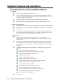
Precautions
Safety Instructions • English
Warning
This symbol is intended to alert the user of important operating and maintenance
(servicing) instructions in the literature provided with the equipment.
Power sources • This equipment should be operated only from the power source indicated on the product. This
equipment is intended to be used with a main power system with a grounded (neutral) conductor. The
third (grounding) pin is a safety feature, do not attempt to bypass or disable it.
This symbol is intended to alert the user of the presence of uninsulated dangerous
voltage within the product’s enclosure that may present a risk of electric shock.
Power disconnection • To remove power from the equipment safely, remove all power cords from the rear of
the equipment, or the desktop power module (if detachable), or from the power source receptacle (wall
plug).
Caution
Read Instructions • Read and understand all safety and operating instructions before using the equipment.
Retain Instructions • The safety instructions should be kept for future reference.
Follow Warnings • Follow all warnings and instructions marked on the equipment or in the user
information.
Avoid Attachments • Do not use tools or attachments that are not recommended by the equipment
manufacturer because they may be hazardous.
Consignes de Sécurité • Français
Power cord protection • Power cords should be routed so that they are not likely to be stepped on or pinched by
items placed upon or against them.
Servicing • Refer all servicing to qualified service personnel. There are no user-serviceable parts inside. To
prevent the risk of shock, do not attempt to service this equipment yourself because opening or removing
covers may expose you to dangerous voltage or other hazards.
Slots and openings • If the equipment has slots or holes in the enclosure, these are provided to prevent
overheating of sensitive components inside. These openings must never be blocked by other objects.
Lithium battery • There is a danger of explosion if battery is incorrectly replaced. Replace it only with the
same or equivalent type recommended by the manufacturer. Dispose of used batteries according to the
manufacturer’s instructions.
Avertissement
Ce symbole sert à avertir l’utilisateur que la documentation fournie avec le matériel
contient des instructions importantes concernant l’exploitation et la maintenance
(réparation).
Alimentations• Ne faire fonctionner ce matériel qu’avec la source d’alimentation indiquée sur l’appareil. Ce
matériel doit être utilisé avec une alimentation principale comportant un fil de terre (neutre). Le troisième
contact (de mise à la terre) constitue un dispositif de sécurité : n’essayez pas de la contourner ni de la
désactiver.
Ce symbole sert à avertir l’utilisateur de la présence dans le boîtier de l’appareil
de tensions dangereuses non isolées posant des risques d’électrocution.
Déconnexion de l’alimentation• Pour mettre le matériel hors tension sans danger, déconnectez tous les cordons
d’alimentation de l’arrière de l’appareil ou du module d’alimentation de bureau (s’il est amovible) ou
encore de la prise secteur.
Attention
Lire les instructions• Prendre connaissance de toutes les consignes de sécurité et d’exploitation avant
d’utiliser le matériel.
Conserver les instructions• Ranger les consignes de sécurité afin de pouvoir les consulter à l’avenir.
Respecter les avertissements • Observer tous les avertissements et consignes marqués sur le matériel ou
présentés dans la documentation utilisateur.
Eviter les pièces de fixation • Ne pas utiliser de pièces de fixation ni d’outils non recommandés par le
fabricant du matériel car cela risquerait de poser certains dangers.
Protection du cordon d’alimentation • Acheminer les cordons d’alimentation de manière à ce que personne ne
risque de marcher dessus et à ce qu’ils ne soient pas écrasés ou pincés par des objets.
Réparation-maintenance • Faire exécuter toutes les interventions de réparation-maintenance par un technicien
qualifié. Aucun des éléments internes ne peut être réparé par l’utilisateur. Afin d’éviter tout danger
d’électrocution, l’utilisateur ne doit pas essayer de procéder lui-même à ces opérations car l’ouverture ou le
retrait des couvercles risquent de l’exposer à de hautes tensions et autres dangers.
Fentes et orifices • Si le boîtier de l’appareil comporte des fentes ou des orifices, ceux-ci servent à empêcher
les composants internes sensibles de surchauffer. Ces ouvertures ne doivent jamais être bloquées par des
objets.
Lithium Batterie • Il a danger d’explosion s’ll y a remplacment incorrect de la batterie. Remplacer uniquement
avec une batterie du meme type ou d’un ype equivalent recommande par le constructeur. Mettre au reut les
batteries usagees conformement aux instructions du fabricant.
Sicherheitsanleitungen • Deutsch
Vorsicht
Dieses Symbol soll dem Benutzer in der im Lieferumfang enthaltenen
Dokumentation besonders wichtige Hinweise zur Bedienung und Wartung
(Instandhaltung) geben.
Stromquellen • Dieses Gerät sollte nur über die auf dem Produkt angegebene Stromquelle betrieben werden.
Dieses Gerät wurde für eine Verwendung mit einer Hauptstromleitung mit einem geerdeten (neutralen)
Leiter konzipiert. Der dritte Kontakt ist für einen Erdanschluß, und stellt eine Sicherheitsfunktion dar. Diese
sollte nicht umgangen oder außer Betrieb gesetzt werden.
Dieses Symbol soll den Benutzer darauf aufmerksam machen, daß im Inneren des
Gehäuses dieses Produktes gefährliche Spannungen, die nicht isoliert sind und
die einen elektrischen Schock verursachen können, herrschen.
Stromunterbrechung • Um das Gerät auf sichere Weise vom Netz zu trennen, sollten Sie alle Netzkabel
aus der Rückseite des Gerätes, aus der externen Stomversorgung (falls dies möglich ist) oder aus der
Wandsteckdose ziehen.
Achtung
Lesen der Anleitungen • Bevor Sie das Gerät zum ersten Mal verwenden, sollten Sie alle Sicherheits-und
Bedienungsanleitungen genau durchlesen und verstehen.
Aufbewahren der Anleitungen • Die Hinweise zur elektrischen Sicherheit des Produktes sollten Sie
aufbewahren, damit Sie im Bedarfsfall darauf zurückgreifen können.
Befolgen der Warnhinweise • Befolgen Sie alle Warnhinweise und Anleitungen auf dem Gerät oder in der
Benutzerdokumentation.
Keine Zusatzgeräte • Verwenden Sie keine Werkzeuge oder Zusatzgeräte, die nicht ausdrücklich vom
Hersteller empfohlen wurden, da diese eine Gefahrenquelle darstellen können.
Instrucciones de seguridad • Español
Schutz des Netzkabels • Netzkabel sollten stets so verlegt werden, daß sie nicht im Weg liegen und niemand
darauf treten kann oder Objekte darauf- oder unmittelbar dagegengestellt werden können.
Wartung • Alle Wartungsmaßnahmen sollten nur von qualifiziertem Servicepersonal durchgeführt werden.
Die internen Komponenten des Gerätes sind wartungsfrei. Zur Vermeidung eines elektrischen Schocks
versuchen Sie in keinem Fall, dieses Gerät selbst öffnen, da beim Entfernen der Abdeckungen die Gefahr
eines elektrischen Schlags und/oder andere Gefahren bestehen.
Schlitze und Öffnungen • Wenn das Gerät Schlitze oder Löcher im Gehäuse aufweist, dienen diese zur
Vermeidung einer Überhitzung der empfindlichen Teile im Inneren. Diese Öffnungen dürfen niemals von
anderen Objekten blockiert werden.
Litium-Batterie • Explosionsgefahr, falls die Batterie nicht richtig ersetzt wird. Ersetzen Sie verbrauchte
Batterien nur durch den gleichen oder einen vergleichbaren Batterietyp, der auch vom Hersteller
empfohlen wird. Entsorgen Sie verbrauchte Batterien bitte gemäß den Herstelleranweisungen.
Advertencia
Este símbolo se utiliza para advertir al usuario sobre instrucciones importantes
de operación y mantenimiento (o cambio de partes) que se desean destacar en el
contenido de la documentación suministrada con los equipos.
Alimentación eléctrica • Este equipo debe conectarse únicamente a la fuente/tipo de alimentación eléctrica
indicada en el mismo. La alimentación eléctrica de este equipo debe provenir de un sistema de distribución
general con conductor neutro a tierra. La tercera pata (puesta a tierra) es una medida de seguridad, no
puentearia ni eliminaria.
Este símbolo se utiliza para advertir al usuario sobre la presencia de elementos con
voltaje peligroso sin protección aislante, que puedan encontrarse dentro de la caja
o alojamiento del producto, y que puedan representar riesgo de electrocución.
Desconexión de alimentación eléctrica • Para desconectar con seguridad la acometida de alimentación eléctrica
al equipo, desenchufar todos los cables de alimentación en el panel trasero del equipo, o desenchufar el
módulo de alimentación (si fuera independiente), o desenchufar el cable del receptáculo de la pared.
Precaucion
Leer las instrucciones • Leer y analizar todas las instrucciones de operación y seguridad, antes de usar el
equipo.
Conservar las instrucciones • Conservar las instrucciones de seguridad para futura consulta.
Obedecer las advertencias • Todas las advertencias e instrucciones marcadas en el equipo o en la
documentación del usuario, deben ser obedecidas.
Evitar el uso de accesorios • No usar herramientas o accesorios que no sean especificamente recomendados
por el fabricante, ya que podrian implicar riesgos.
安全须知 • 中文
这个符号提示用户该设备用户手册中有重要的操作和维护说明。
这个符号警告用户该设备机壳内有暴露的危险电压,有触电危险。
注意
阅读说明书 • 用户使用该设备前必须阅读并理解所有安全和使用说明。
保存说明书 • 用户应保存安全说明书以备将来使用。
遵守警告 • 用户应遵守产品和用户指南上的所有安全和操作说明。
避免追加 • 不要使用该产品厂商没有推荐的工具或追加设备,以避免危险。
Protección del cables de alimentación • Los cables de alimentación eléctrica se deben instalar en lugares donde
no sean pisados ni apretados por objetos que se puedan apoyar sobre ellos.
Reparaciones/mantenimiento • Solicitar siempre los servicios técnicos de personal calificado. En el interior no
hay partes a las que el usuario deba acceder. Para evitar riesgo de electrocución, no intentar personalmente
la reparación/mantenimiento de este equipo, ya que al abrir o extraer las tapas puede quedar expuesto a
voltajes peligrosos u otros riesgos.
Ranuras y aberturas • Si el equipo posee ranuras o orificios en su caja/alojamiento, es para evitar el
sobrecalientamiento de componentes internos sensibles. Estas aberturas nunca se deben obstruir con otros
objetos.
Batería de litio • Existe riesgo de explosión si esta batería se coloca en la posición incorrecta. Cambiar esta
batería únicamente con el mismo tipo (o su equivalente) recomendado por el fabricante. Desachar las
baterías usadas siguiendo las instrucciones del fabricante.
警告
电源 • 该设备只能使用产品上标明的电源。 设备必须使用有地线的供电系统供电。 第三条线
(地线)是安全设施,不能不用或跳过 。
拔掉电源 • 为安全地从设备拔掉电源,请拔掉所有设备后或桌面电源的电源线,或任何接到市
电系统的电源线。
电源线保护 • 妥善布线, 避免被踩踏,或重物挤压。
维护 • 所有维修必须由认证的维修人员进行。 设备内部没有用户可以更换的零件。为避免出
现触电危险不要自己试图打开设备盖子维修该设备。
通风孔 • 有些设备机壳上有通风槽或孔,它们是用来防止机内敏感元件过热。 不要用任何东
西挡住通风孔。
锂电池 • 不正确的更换电池会有爆炸的危险。必须使用与厂家推荐的相同或相近型号的电池。
按照生产厂的建议处理废弃电池。
FCC Class A Notice
This equipment has been tested and found to comply with the limits for a Class A digital device, pursuant to part 15 of the FCC Rules. Operation is subject to
the following two conditions: (1) this device may not cause harmful interference, and (2) this device must accept any interference received, including interference
that may cause undesired operation. The Class A limits are designed to provide reasonable protection against harmful interference when the equipment is
operated in a commercial environment. This equipment generates, uses, and can radiate radio frequency energy and, if not installed and used in accordance with
the instruction manual, may cause harmful interference to radio communications. Operation of this equipment in a residential area is likely to cause harmful
interference, in which case the user will be required to correct the interference at his own expense.
N
This unit was tested with shielded cables on the peripheral devices. Shielded cables must be used with the unit to ensure compliance with FCC emissions limits.
For more information on safety guidelines, regulatory compliances,
EMI/EMF compliance, accessibility, and related topics, click here.
Table of Contents
Chapter One • Introduction . ..................................................................................................... 1-1
About This Manual..................................................................................................................... 1-2
About the IPL 250. ...................................................................................................................... 1-2
Features....................................................................................................................................... 1-2
General features................................................................................................................... 1-2
Network and configuration features.................................................................................. 1-2
Controlling other devices......................................................................................................... 1-3
IR and RS-232 Device Control.............................................................................................. 1-3
How the IPL 250 Works: Components and Interactions...................................... 1-4
Creating a Control System Using the IPL with Optional
Extron TouchLink™ Touchpanels......................................................................................... 1-5
System Requirements.............................................................................................................. 1-5
Hardware requirements. .......................................................................................................... 1-5
Software requirements............................................................................................................. 1-5
Chapter Two • Hardware Features and Installation. .............................................. 2-1
Setup Checklist: How to Proceed With Installation............................................... 2-2
Front Panel Features................................................................................................................. 2-3
IR learning sensor...................................................................................................................... 2-3
Reset features............................................................................................................................. 2-3
Mounting the IPL 250............................................................................................................... 2-4
Rack mounting........................................................................................................................... 2-4
UL rack mounting guidelines............................................................................................... 2-4
Rack mounting with a rack shelf......................................................................................... 2-4
Rack mounting with brackets.............................................................................................. 2-5
Furniture mounting................................................................................................................... 2-5
Mounting to a projector mount pole..................................................................................... 2-5
Rear Panel Features and Connections............................................................................ 2-6
Power connection...................................................................................................................... 2-6
Bidirectional control and communication connections....................................................... 2-6
Unidirectional control and communication connections. ................................................... 2-8
Resetting the Unit................................................................................................................... 2-10
Application Diagram. ............................................................................................................. 2-11
Chapter Three • Software-based Configuration and Control......................... 3-1
Configuration and Control: an Overview.................................................................... 3-2
The Basic Setup Steps: a Guide to this Chapter and Other Resources....... 3-2
IPL 250 • Table of Contents
TOC-i
Table of Contents, cont’d
Communicating with the IPL............................................................................................... 3-3
Configuring the IPL for Network Communication................................................. 3-3
Configuring the IPL for network use via Global Configurator........................................... 3-3
Configuring the IPL for network use via the ARP command.............................................. 3-4
Configuring the IPL for network use via a Web browser.................................................... 3-5
Configuring the IPL for network use via SIS™ commands and Telnet................................ 3-6
Setting up the PC for IP communication with an IPL 250.................................................... 3-7
Global Configurator Software for Windows® .......................................................... 3-9
Downloading the software and getting started................................................................. 3-10
PC system requirements.......................................................................................................... 3-10
For the IPL, Global Configurator....................................................................................... 3-10
For a system that includes TouchLink touchpanels and GUI Configurator..................... 3-10
Using Global Configurator: helpful tips............................................................................... 3-10
Resources and notes........................................................................................................... 3-10
A brief guide to Global Configurator’s tabs..................................................................... 3-11
Advanced Configuration...................................................................................................... 3-12
IR learning to create customized IR driver files. ................................................................. 3-12
Printing a wiring block diagram or a GUI configuration report. ..................................... 3-12
Updating firmware.................................................................................................................. 3-12
Advanced serial port control. ................................................................................................ 3-13
Serial pass-through (redirect mode).................................................................................. 3-13
Direct port access (ports 2001 through 2003)................................................................... 3-14
Serial bridging.................................................................................................................... 3-15
Hardware connection................................................................................................... 3-15
Serial bridge configuration.......................................................................................... 3-15
Saving and uploading the configuration............................................................................. 3-16
Controlling an IPL 250............................................................................................................ 3-17
Embedded Web pages............................................................................................................ 3-17
Status................................................................................................................................... 3-18
System Status................................................................................................................ 3-18
Configuration..................................................................................................................... 3-19
System Settings............................................................................................................. 3-19
Port Settings.................................................................................................................. 3-20
IR Drivers....................................................................................................................... 3-21
Passwords...................................................................................................................... 3-21
Email Alerts................................................................................................................... 3-22
Firmware Upgrade........................................................................................................ 3-22
File Management............................................................................................................... 3-23
GlobalViewer® Web Pages...................................................................................................... 3-24
Controlling the IPL 250 with a Touchpanel............................................................... 3-27
Customizing the IPL’s Control Web Pages. ................................................................ 3-28
Troubleshooting......................................................................................................................... 3-29
Power connections. ................................................................................................................. 3-29
Data connections..................................................................................................................... 3-29
Device control connections and configuration................................................................... 3-29
TOC-ii IPL 250 • Table of Contents
Chapter Four • SIS™ Programming and Control......................................................... 4-1
Host-to-IPL Communications. .............................................................................................. 4-2
IPL 250-initiated messages. ...................................................................................................... 4-2
Password information............................................................................................................... 4-2
Error responses........................................................................................................................... 4-3
Error response references......................................................................................................... 4-3
Commands and Reponses...................................................................................................... 4-3
Using the command/response tables...................................................................................... 4-3
Entering SIS commands: helpful tips. ..................................................................................... 4-4
Symbol definitions..................................................................................................................... 4-5
Command/response table for SIS commands. ....................................................................... 4-8
Chapter Five • Special Applications. ................................................................................... 5-1
Customizing HTML Files to Control Devices, Modify Embedded Web
Pages, and Send E-mail Alerts..............................................................................................5-2
Creating and using server side includes (SSIs)....................................................................... 5-2
About server side includes and the IPL 250........................................................................ 5-2
SSI command types and syntax............................................................................................ 5-3
Host vs. remote commands............................................................................................ 5-3
Command syntax............................................................................................................ 5-3
Example: SSI use in notification e‑mails........................................................................ 5-3
SSI use in an IPL’s Web page........................................................................................... 5-4
Creating and using query strings. ........................................................................................... 5-5
Query string command types and syntax............................................................................ 5-5
Host vs. remote commands............................................................................................ 5-5
Command syntax............................................................................................................ 5-5
Appendix A • Reference Material......................................................................................... A-1
Specifications............................................................................................................................... A-2
Part Numbers................................................................................................................................ A-4
Included parts............................................................................................................................ A-4
Accessories................................................................................................................................. A-4
Cables. ........................................................................................................................................ A-5
Glossary........................................................................................................................................... A-5
File Types: a Key to Extron-specific File Names...................................................... A-7
IPL 250 • Table of Contents TOC-iii
Table of Contents, cont’d
Appendix B • Firmware Updates............................................................................................B-1
Determining the Firmware Version.................................................................................B-2
Using the Global Configurator software. ..............................................................................B-2
Using a Web browser................................................................................................................B-2
Updating the Main Firmware..............................................................................................B-4
Locating and downloading the firmware..............................................................................B-4
Updating firmware via the IPL 250’s embedded Web page................................................B-4
Updating firmware via Extron Firmware Loader software.................................................B-5
Updating firmware via Extron IP Link™ File Manager software.........................................B-7
Appendix C • Index. ..........................................................................................................................C-1
Index...................................................................................................................................................C-2
All trademarks mentioned in this manual are the properties of their respective owners.
68-1715-01 Rev. A
08 09
TOC-iv IPL 250 • Table of Contents
IPL 250
1
Chapter One
Introduction
About This Manual
About the IPL 250
IR and RS-232 Device Control
How the IPL 250 Works: Components and Interactions
Optional TouchLink Touchpanels
System Requirements
Introduction
About This Manual
This manual provides detailed information and best practices recommendations
about cabling and configuring the Extron IPL 250 IP Link® Ethernet Control
Processor and reference information about the controller’s specifications,
programming, and special applications.
It does not contain instructions on the most basic setup steps: those are covered in
the IPL 250 Setup Guide, which describes how to set up the hardware, how to use
the Global Configurator (GC) program to download drivers, add A/V devices to a
GC configuration, configure the front panel buttons, set a shutdown schedule, and
set up e-mail alerts to flag a projector disconnection or warn that lamp hours are
exceeded.
About the IPL 250
The IPL 250 is capable of controlling a projector, source devices, switchers, and
various other items such as lights, a projector lift, or a screen motor in a distributed
control system environment or as a stand-alone controller. It allows legacy
products to be linked to and controlled via a network. Throughout this manual the
IPL 250 is also referred to as the IPL, “Ethernet control processor,”or “controller.”
Features
General features
Flexible options for device control — The IPL offers RS-232 and IR-based
projector/display/source control; relays for controlling items such as a
projector lift, motorized projection screen, and lights; and contact closure
input control of the relays.
A variety of mounting options — The 1U high, one quarter rack wide enclosure can
be rack mounted, furniture mounted, or mounted to a projector mount pole.
Universal power system compatibility — The IPL includes an external power
supply that accepts 100-240 VAC, 50-60Hz input.
Network and configuration features
The IPL 250 can be configured and controlled via a host computer via IP Link
Ethernet control. Setup and control can be accomplished by simple ASCII
commands (Simple Instruction Set, SIS™) or via the included Global Configurator
program. The software offers many more setup options than does SIS
programming. After being configured, the IPL 250 can be controlled by an Extron
TouchLink™ touchpanel connected to the same network.
Via Ethernet/IP communication you can access the IPL 250’s embedded Web pages,
which include online diagnostics and monitoring of basic control features. As an
integrated part of the IPL 250, IP Link provides the following advantages:
Global compatibility — The IPL uses standard Ethernet communication protocols,
including ARP, DHCP, ICMP (ping), TCP, IP, Telnet, HTTP, and SMTP.
Embedded Web page serving — The IPL 250 offers up to 7.25 MB of flash memory
for storing Extron and user-supplied Web pages, configuration settings, and
device drivers. Data in flash memory is served at a transfer rate of 6 Mbits
per second.
Remote equipment management — The IP Link connection allows you to remotely
manage projectors, cameras, video conferencing equipment, switchers, and
other A/V equipment.
Multi-user support — Up to two hundred (200) simultaneous connections enable
each IP Link device to support many concurrent users and improve system
throughput by sending information in parallel.
1-2
IPL 250 • Introduction
Built-in multilevel security — The user controls access to the devices attached to the
controller. Two levels of password protection provide appropriate security.
Management ability via Global Configurator 3.0 and higher — The included
software and the GlobalViewer Web pages associated with it allow you to
control, monitor, and schedule various functions of devices connected to
IP Link products such as the IPL.
E-mail notification — The IPL 250 can be set up to send an e-mail when a projector
has been disconnected or the projector’s lamp has been used for a designated
number of hours.
Controlling other devices
The IPL 250 offers RS-232, infrared (IR), and relay device control. It can learn IR
signals from remote controls to communicate with sources such as VCRs and DVD
players. Users can create their own device drivers (IR) or go to the Extron Web site
(www.extron.com) to obtain device drivers.
Extron
TLP 700MV
7" TouchLink
Panel
Extron
IPL 250
TCP/IP
Network
IP Link Ethernet
Control Processor
VCR
DVD
DOC
CAM
TOP
LAP
PC
ON
OFF
Y
PLA
DIS TE
MU
Ext
ron
Y
LA 2
EEN
SCR
UP
RE
1
EEN
SCR N
DOW
IR 2
Motion
Detector
Extron
IN1508
Scaling Presentation
Switcher
M
CO
RX
TX
TX
N
1
G
S
S
G
Y
LA 4
RE
3
IR 4
M
CO
RX
TX
LA
1
2
M1 SC TS
CO RT
RX
T
PU 4
IN
3
2
3
3
S
G
S
G
WER
PO
V
12 A
0m
50
MAX
T
2
PU
-23
OUT
RS
A
B
L
6
O
DI 3
T
PU 4
IN
5
8
L
R
RS-232
AU
Extron
XPA 1002
Power Amplifier
2
1
T
L
Y
R
PU
OUT
ED
LIST
1T23.
U S I.T.E
C
Y,
B
RG RY,
B-
6
8
I
B
DV
RG
B
7
RG
3 YC
IR Control
to DVD
Contact
Closure
R
7
Extron
SI 28
Surface-mount
Speakers
Relay
Y
R1 VID
z
60H
500V
-24
100
B-
I
N
U
T
Y
5
XPA
1002
Y
VID
P
4
T
OTEC
2
1
OVER
TEMP
2
ER/PR
LIMIT L
SIGNA
RS-232
Relay
Extron
IR Emitter
Lighting
System
Screen
Control
Laptop
DVD Player
Projector
IR Control
from IPL 250
PC
DVI Output
A typical IPL 250 application with a TouchLink panel
IR and RS-232 Device Control
The IPL must be configured in one of the following ways before it will send
commands to a projector/display/source:
• An IR or an RS-232 driver file can be installed from a disk, downloaded from the
Extron Web site (www.extron.com), or downloaded from Extron using the driver
subscription feature within Global Configurator. The driver is saved to a folder
and uploaded to the IPL via Global Configurator.
• RS-232 command strings can be entered directly from a host computer using
Extron Global Configurator software.
• IR commands can be entered directly from an IR remote control through IR
learning and the Extron IR Learner software to create a driver that the IPL can
IPL 250 • Introduction
1-3
Introduction, cont’d
use. IR learning is convenient for installing new or updated commands into the
IPL 250 in the field.
Refer to the Global Configurator help file or the IR Learner help file (which
comes with the software) for details on setting up the IPL and for downloading,
programming, or learning device control commands.
How the IPL 250 Works: Components and Interactions
The IPL 250 requires and uses event files to perform functions. The event files
define, monitor, and govern how an IPL 250 works. The following diagrams are
examples of how the IPL interacts with accessories, event scripts, drivers, ports, and
input and output devices.
IPL 250
TouchLink™
touchpanel
PC
with
Global
Configurator
or
Web
Browser
Front
Panel
LEDs
TCP/IP
Network
LAN
Port
Memory
IPL 250
Firmware
MAIN EVENT
(___.evt)
Proj. Driver
(___.evt)
Serial
Driver
RS-232
Com Port
2-way
RS-232
Proj.
DVD Driver
(___.evt)
Contact
Closure
Control
IR
Port
Relay
Port
IR
DVD
Player
Screen
Control
The IPL can be configured completely via Global Configurator software. Once you
have set up how you want it to work (assigned drivers to ports, configured relays
and contact closure input, and set up IP addresses and functions), that information
is saved to a project file that is uploaded into the IPL.
The configuration information is used to create the “main event” (0.evt) script file
that defines the IPL’s operation. The main event file also controls and monitors
ports and optional control accessories. Scripts are compiled to generate the main
event file to monitor events and to generate actions (such as issuing commands and
triggering relays).
1-4
IPL 250 • Introduction
Creating a Control System Using the IPL with Optional
Extron TouchLink™ Touchpanels
Not only can the IPL 250 act as a stand-alone controller that can be accessed via
its internal and GlobalViewer Web pages, but it also can act as the centerpiece of
a control system that features Extron TouchLink Touchpanels. The touchpanels
provide a convenient, aesthetically pleasing interface for controlling the IPL, which,
in turn, controls the other system components.
If you have additional questions or need support for your Extron control system
installation, contact the Extron S3 Control Systems Support Hotline.
System Requirements
The IPL 250 and Global Configurator have the following hardware and software
requirements:
Hardware requirements
• Intel® Pentium® III, 1 GHz processor
• 512 MB of RAM
• 50 MB of available hard disk space
• A network connection with a minimum data transfer rate of 10 Mbps (100 Mbps
is recommended)
Software requirements
For GUI Configurator and Global Configurator 3:
• Microsoft® Windows® operating system
○ Windows XP service pack 2,
○ Windows Vista® or
○ a higher version of Windows
C
Do not run Global Configurator software on a PC that uses an earlier
version of Windows.
Global Configurator has the following system requirements in addition to those
listed above:
• Microsoft Internet Explorer® 6.0 or higher with ActiveX® enabled
• Microsoft Windows Script 5.6
IPL 250 • Introduction
1-5
Introduction, cont’d
1-6
IPL 250 • Introduction
IPL 250
2
Chapter Two
Hardware Features and
Installation
Setup Checklist: How to Proceed With Installation
Front Panel Features
Mounting the IPL 250
Rear Panel Features and Connections
Resetting the Unit
Application Diagram
Hardware Features and Installation
Setup Checklist: How to Proceed With Installation
Get Ready
Familiarize yourself with the IPL 250's features.
Download and install the latest version of the Extron Global Configurator software
(version 3.0 or higher) and the latest driver package (available from www.extron.com
or the Extron Software Products Disk.)
Obtain IP setting information from the network administrator for the IPL.
Obtain model names and setup information for devices that the IPL will control.
Perform Physical Installation
Mount the unit to a rack, furniture, or projector mount. (See the instructions in this chapter.)
Connect power cords and turn on the devices in the following order: output devices
(projectors, monitors, speakers), the IPL, a PC (for setup) or touchpanel (for control
after configuration), then all input devices (DSS, cable boxes, etc.).
Cable devices to ports on the IPL 250. (See chapter 2 of this manual or of the IPL 250
Setup Guide.)
Configure the IPL
the PC to the IPL 250 via Ethernet patch or crossover cable (see
Connect
chapter 2) and use Telnet or a similar application to configure the IPL for network
communication.
Connect any TLP touchpanels that will be part of the system to the same network as
the PC and IPL. Create a user interface layout for the touchpanels and upload the
GUI configuration to each touchpanel. (See the GUI Configurator software help file
for details.)
the IPL 250 using Global Configurator. (Refer to the Global Configurator
Configure
Help file.)
Create a new Global Configurator project.
Set the IPL’s IP address, subnet mask, and other IP settings.
Define the unit’s GlobalViewer Tree location.
Add the IPL to the project.
Define e‑mail settings and contacts.
Add serial, IR, and Ethernet device drivers.
Configure the IPL’s ports and assign device drivers as needed.
Configure touchpanel buttons, if applicable, in GC.
Create a display shutdown schedule.
Create a display lamp hours notification e‑mail.
Create a display disconnection notification e‑mail.
Perform configurations for special applications, if needed.
Save the Global Configurator project/configuration.
Build and upload the configuration.
Test the system.
2-2
IPL 250 • Hardware Features and Installation
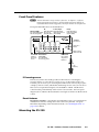
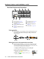
Front Panel Features
N The IPL 250 must be set up in order to function. See chapter 3, “Softwarebased Configuration and Control,” and the Global Configurator help file for
information about Global Configurator, which you must use to set up the unit.
Front panel LED indications are described below.
Contact Input:
IR:
RS-232 (COM):
LED Lights When LED Lights When
Input Port is Closed
TX = Transmitting Data IR Port (1-4)
RX= Receiving Data
Transmits Data (tied to GND)
Relay:
LED Lights When
Relay is Activated
(tied to GND)
®
IPL 250
COM
TX
INPUT
RELAY
1
1
100 Mbps
Connection
RX
1
R
IR
1
3
3
3
100
2
LINK
3
ACT
2
4
2
4
2
Network is
Active
4
Data is Being
Sent/received.
Power LED:
Lit When
Receiving
Power
Reset Button
(recessed):
See “Resetting
the Unit,” pg. 2-10
IR Receiver:
IR Learning
Angle and
Distance
2–12"
(4–30 cm)
1
2
3
4
5
6
7
8
9
0
IR learning sensor
In most cases, Extron has already produced a driver file for controlling the
projector, display, or source device you plan to use. If a device driver file is not
available, you can create your own using Extron IR Learner software, the projector
or display’s remote control, and the IPL’s IR learning receiver sensor, shown above.
This receiver accepts infrared signals of from 30 kHz to 1 MHz. The IR remote
control must be pointed directly at the receiver for best results. The front panel
diagram (above) indicates the best distances and angles at which to hold the remote
control.
Reset features
Reset button and LED — Pressing this recessed button causes various IP functions
and Ethernet connection settings to be reset to the factory defaults. The green
LED flashes depending on the selected reset mode. See “Resetting the Unit” on
page 2‑10 for details.
Mounting the IPL 250
IPL 250 • Hardware Features and Installation
2-3
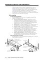
Hardware Features and Installation
Optional rack shelves and an assortment of mounting kits (back of the rack,
furniture, and projector pole mount) are available for use with the IPL. See
appendix A for part numbers of these accessories, and read the instructions that
come with the rack shelf or mounting kit for installation procedures.
The IPL 250 includes rubber feet so it can be set on a table. If you are going to
mount the unit to a rack, rack shelf, furniture, or pole, and these feet were attached
to the enclosure, remove the feet before mounting.
Rack mounting
UL rack mounting guidelines
The following Underwriters Laboratories (UL) guidelines pertain to the safe
installation of the IPL 250 in a rack.
1.
Elevated operating ambient temperature — If installed in a closed or
multi-unit rack assembly, the operating ambient temperature of the rack
environment may be greater than room ambient temperature. Therefore,
install the IPL in an environment compatible with the maximum ambient
temperature (Tma = +122 °F, +50 °C) specified by Extron.
2.
Reduced air flow — Install the equipment in a rack so that the amount of air
flow required for safe operation of the equipment is not compromised.
3.
Mechanical loading — Mount the equipment in the rack so that a hazardous
condition is not achieved due to uneven mechanical loading.
4.
Circuit overloading — Connect the equipment to the supply circuit and
consider the effect that circuit overloading might have on overcurrent
protection and supply wiring. Appropriate consideration of equipment
nameplate ratings should be used when addressing this concern.
5.
Reliable earthing (grounding) — Maintain reliable grounding of rackmounted equipment. Pay particular attention
to supply connections other
QuarterRackVersaToolsShelf
than direct connections to the branch circuit (e.g. use of power strips).
QuarterRackStandardShelf
Rack mounting with a rack shelf
Mount the unit on an optional 1U rack shelf and install blank panels or other units
to the rack shelf as shown below.
1U Universal Rack Shelf
1/2 Rack Width Front False
Faceplate
1/4 Rack Width Front False
Faceplate
Both front false faceplates
use 2 screws.
Use 2 mounting holes on
opposite corners.
2-4
VersaTools Rack Shelf
1/4 Rack Width Front
False Faceplate
(2) 4-40 x 3/16"
Screws
IPL 250 • Hardware Features and Installation
Use 2 mounting holes on
opposite corners.
(2) 4-40 x 3/16"
Screws
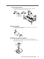
Rack mounting with brackets
Installation instructions are available with the optional Extron MBB 100
back of the rack mounting kit (part number 70‑367‑01).
POWER
12V
.5A MAX
1
3
2
Mounting
Pre-installation
1
L
1
R
2
L
ML
S 103
AUD
V
2 IO INPU INP
UTS
R
L TS
3
R
L
3
4
R
AUX/
MONMIX
O
OUT
L
PRE
PUT
AMP
R
12V
MLC
/RS
POW -232
ER
A
B
.5A
1
MA
L
X
1
R
2
L
ML
S 103
AUD
2 IO INPU INP
UTS
R
L TS
3
R
L
V
3
4
R
AUX/
MONMIX
O
OUT
L
PRE
PUT
AMP
R
12V
MLC
/RS
POW -232
ER
A
B
.5A
MA
X
1
L
1
R
2
L
AUD
2 IO
R
ML
S 103
V
INPU
INP
UTS
L TS
3
R
L
3
4
R
AUX/
MONMIX
O
OUT
L
PRE
PUT
AMP
R
1
OU
TP
2
UT
12V
1
MLC
/RS
POW -232
ER
A
B
.5A
MA
X
3
1
OU
TP
2
UT
2
3
MM
X
32
VG
A
A
QuarterRackUnderdeskMounting
Furniture mounting
You can furniture mount the IPL 250 using an optional MBU 123 Under-Desk
Mount Kit (Extron part 70‑212‑01).
Mounting to a projector mount pole
Several optional pole mounting kits are available for use with the IPL 250,
either multiproduct mounting kits or an optional Extron PMK 100 pole mount kit
(part #70‑217‑01, shown here).
Projector
Mounting
Bracket
Mounting
Bolt
Projector
IPL 250 • Hardware Features and Installation
2-5
Hardware Features and Installation, cont’d
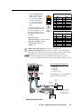
Rear Panel Features and Connections
8
3
COM1
TX RX RTS CTS
MAC: 00-05-A6-XX-XX-XX
S/N:
POWER
12V
500mA
MAX
4
COM 2
TX RX
5
1
IR
6
2
RELAY
2
1
S G S G
LAN
1
INPUT
2 3 4
COM 3
TX RX
3
IR
4
RELAY
4
3
S G S G
1
a
b
2
7
Power connector (page 2-6)
LAN (Ethernet, IP) connector
and LEDs (page 2-6)
c
COM1 configurable RS‑232 port
(page 2-7)
d
COM2 and COM3 RS‑232 ports
(page 2-7)
e
f
g
IR output ports 1-4 (page 2-8)
h
MAC address — (page 2-9)
Relay ports 1-4 (page 2-9)
Input (contact input) ports
(page 2-9)
Power connection
a
Power connector — To power the IPL, connect a cable between this port and
the included 12 VDC, 1 amp (maximum) power supply. The Extron power
supply included with the IPL is ready to plug in. Wiring is shown in the
following diagram.
Smooth
Ridges
A
Tie Wrap
A
SECTION A–A
Power Supply
Output Cord
3/16”
(5 mm) Max.
2-Pole Captive Screw
Connector
Bidirectional control and communication connections
b
LAN (IP) connector and LEDs — To connect and to control the IPL and the
devices connected to it in an Ethernet network, plug a cable into this RJ-45
socket and connect the other end of the cable to a network switch, hub, router,
or PC connected to an Ethernet LAN or the Internet.
• For 10Base-T (10 Mbps) networks, use a CAT 3 or better cable.
• For 100 Base-T (max. 155 Mbps) networks, use a CAT 5 cable.
You must configure this port before using it.
2-6
LAN
Activity LED — This yellow LED blinks to indicate
network activity.
RJ-45
Port
Link LED — This green LED lights to indicate a good
network connection.
Link
LED
IPL 250 • Hardware Features and Installation
Activity
LED
• Use a straight-through
cable for connection to a
switch, hub, or router.
Pins:
12345678
Straight-through Cable
(for connection to a switch, hub, or router)
End 1
• Use a crossover cable for
connection directly to a
PC. Wire the connector
as shown in the tables at
right.
Configure the settings for this
port via either SIS commands
or Global Configurator. See
the programming sections of
this manual (chapters 3 and 4)
for details.
Insert Twisted
Pair Wires
Pin
1
2
3
4
5
6
7
8
RJ-45
Connector
Wire Color
white-orange
orange
white-green
blue
white-blue
green
white-brown
brown
End 2
Pin
1
2
3
4
5
6
7
8
Wire Color
white-orange
orange
white-green
blue
white-blue
green
white-brown
brown
Crossover Cable
(for direct connection to a PC)
End 1
Pin
1
2
3
4
5
6
7
8
Wire Color
white-orange
orange
white-green
blue
white-blue
green
white-brown
brown
LAN port defaults:
• IPL 250’s IP address: 192.168.254.254
• gateway’s IP address: 0.0.0.0
• subnet mask: 255.255.0.0
• DHCP: off
c
d
COM1 configurable RS‑232 port (-5 VDC to +5 VDC) and
End 2
Pin
1
2
3
4
5
6
7
8
Wire Color
white-green
green
white-orange
blue
white-blue
orange
white-brown
brown
COM2 and COM3 RS‑232 ports (-5 VDC to +5 VDC) — Use COM ports for
serial control of a display or other device and to receive status messages from the
connected devices. These ports can send commands from a driver file.
N The 5-pole COM1 port supports both hardware and software flow control.
The 3-pole COM2 and COM3 ports support software (XON, XOFF) flow control.
COM1
TX RX RTS CTS
COM 2
TX RX
IPL 250
Rear Panel
Heat Shrink
Over Shield
IPL 250 default RS-232 protocol:
• 9600 baud
• 8 data bits
• 1 stop bit
• no parity
• no flow control
Use this diagram as a wiring guide to
cable the IPL to other devices.
Heat Shrink
over Shield
Ground ( )
Rx Receive
Tx Transmit
CTS Clear to send
RTS Request to send
Ground ( )
Receive
Rx
Transmit
Tx
Bidirectional
RS-232
Strip wires
3/16”
(5 mm)
max.
Transmit (Tx)
Receive (Rx)
N If you use cable that
has a drain wire, tie
the drain wire to
ground at both ends.
Transmit (Tx)
Receive (Rx)
Heat Shrink
Over Shield
RS-232Controllable
Device
Projector/
Panel Display/
PC/ Other
RS-232 Device
Wiring for RS-232 control
IPL 250 • Hardware Features and Installation
2-7
Hardware Features and Installation, cont’d
For bidirectional RS-232 communication, the transmit, ground, and receive
pins must be wired at both the IPL 250 and the other device. Each projector
or other device may require different wiring. For details, refer to that
equipment’s manual or to the Extron device driver communication sheet.
N Maximum distances between the IPL and the device being controlled may vary
up to 200 feet (61 m). Factors such as cable gauge, baud rates, environment,
and output levels (from the IPL and the device being controlled) all affect
transmission distance. Distances of about 50 feet (15 m) are typically not a
problem. In some cases the IPL may be capable of transmitting and controlling a
given device via RS‑232 up to 250 feet (76 m)
3/16”
away, but the RS-232 response levels of that device
(5 mm) Max.
may be too low for the IPL to detect.
7/8”
(22 mm)
Extron Comm-Link (CTL and CTLP) cable is
recommended for these connections. Before
inserting wires in the connectors, strip the cable and
apply heat shrink as shown at right.
T
Heat Shrink on
Outer Jacket to
Inner Conductor
Transition
For best results and to avoid short circuits, Extron
recommends using shielded wires or wires insulated
using heat shrink (instead of bare wires) for the
common/drain wires.
Extron
Comm-Link Cable
Unidirectional control and communication connections
e
IR output ports — An IPL 250 can use infrared signals to control up to 16
devices. You can connect one of these ports directly to the wired IR port of
another device. Or you can insert the wires from up to four IR Emitters in
an IR port and place the emitters’ heads over or next to the devices’ IR signal
pickup windows. The figure below shows some wiring examples.
1
IR
2
S G S G
To Projector,
Panel Display,
or Source
Device’s Wired
IR Remote Port
IPL 250
Rear Panel
Strip wires
3/16”
(5 mm)
max.
IR Output
Ground ( )
Ground ( )
IR Output Signal
Unidirectional IR
(-)
(-)
(+)
(+)
(+)
(-)
Wiring the IR ports
Two Single IR Emitters
N Each emitter must be within 100’ of the IPL for best control results.
2-8
•
If using all single emitters or all double emitters, wire the emitters in
parallel.
•
If using a mix of both single and dual emitters, see the following figure
and the IR Emitter Installation Guide, part number 68-808-01.
IPL 250 • Hardware Features and Installation
IR Signal
Ground
(+)
Ground
(-)
IR Signal
(+)
(-)
(-)
(+)
(+)
(+)
(-)
(-)
Single and Dual IR Emitter
Two Single IR Emitters
(-)
(-)
Ground
IR Signal
(-)
IR Signal
(+)
(+)
(+)
(+)
(+)
(+)
Ground
(-)
(-)
(+)
(-)
(-)
Dual IR Emitters
Two Single and 0ne Dual IR Emitter
Legend
(–)
(+)
Black wire
Black wire
w/white stripe
Wiring emitters for IR control
f
Relay ports — Four relay ports provide control for power, screen/projector
lifts, window coverings, and similar items, when trigger events occur.
These relay contacts may be used to control any
equipment as long as the contact specifications
of a total of 24 volts at 1 ampere are not exceeded
for each port. These relays are normally open by
default.
When activated, the closed contacts open, and
the open contacts close. They can be set up to
operate in one of two ways:
Normally
open
Closed
RELAY
2
1
IPL 250
Rear Panel
• latching (brief contact) (press to turn on, press
to turn off), or
• momentary (timed) (press to turn on, timeout
to turn off).
g
h
In the timed mode the default timeout period is
½ second (500 ms). Use the GC software or SIS
commands to change the length of the timeout
period. See X6# in “Serial Communication”,
chapter 4, for details.
Input (contact closure input) ports — To allow the IPL 250 to monitor devices to
trigger events, connect a switch, sensor, or
similar item to one of these four ports. See the
figure at right for an example.
A 1k ohm pull-up resistor in a TTL (5 VDC)
circuit senses external switch or contact
closure. After these ports have been
configured, when the circuit between a signal
pin and a ground pin is closed, each port can
trigger events (such as toggling relays, issuing
commands, or sending an e-mail).
MAC address — This is the unique user
hardware ID number (MAC address) of the
unit (for example, 00-05-A6-00-00-01). You
may need this address during configuration.
To Room
Control
Equipment
1
INPUT
2 3 4
IPL 250
Rear Panel
Heat Shrink
Over Shield
4
3
2
1
IPL 250 • Hardware Features and Installation
Switch,
Sensor
2-9
Hardware Features and Installation, cont’d
Resetting the Unit
There are five reset modes that are available by pressing the
Reset button on the front panel. The Reset button is recessed,
so use a pointed stylus, ballpoint pen, or Extron Tweeker to
access it. See the following table for a summary of the modes.
C
IPL 250
Review the reset modes carefully. Using the wrong
reset mode may result in unintended loss of flash
memory programming, port reassignment, or an IPL
unit reboot
The reset modes (with the exception of Mode 2) close all open
IP and Telnet connections and close all sockets.
R
Power
LED
Reset
button
N If you hold down the reset button continuously, every 3 seconds the LED blinks,
the unit enters a different mode from Modes 3 through 5. For Mode 5 the LED
blinks three times, the third blink indicating the last mode. The modes are
separate functions, not a continuation from Mode 1 to Mode 5.
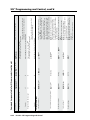
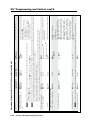
IPL 250 Reset Mode Summary
Mode Activation
Run/Stop
Enable
Events Serial Console
Use Factory
Firmware
1
N After a mode 1 reset is performed,
update the IPL’s firmware to the latest
version. Do not operate the IPL firmware version that results from the mode 1
reset. If you want to use the factory
default firmware, you must upload that
version again. See appendix B, for
details on uploading firmware.
2
3
Reset all
IP Settings
Reset to
Factory Defaults
Purpose/Notes
The IPL reverts to the factory default firmware.
Event scripting does not start if the IPL is powered on
in this mode. All user files and settings (drivers,
adjustments, IP settings, etc.) are maintained.
Use mode 1 to revert
to the factory default
firmware version if
incompatibility issues
arise with user-loaded
firmware.
N If you do not want to update firmware, or you
performed a mode 1 reset by mistake, cycle power to the
IPL to return to the firmware version that was running
prior to the mode 1 reset. Use the 0Q SIS command to
confirm that the factory default firmware is no longer
running (look for asterisks following the version number.)
N User-defined
Web pages may not
work correctly if
using an earlier
firmware version.
The connected COM port becomes a console port to
send SIS commands. Scripting remains on.
Mode 2 enables the
SIS console port
Hold down the Reset button for about 3
sec. until the Power LED blinks once,
then release and press Reset
momentarily (<1 sec.) within 1 second.
Mode 3 turns events on or off.
Mode 3 is useful for
troubleshooting.
Hold down the Reset button for about
6 sec. until the Power LED blinks twice
(once at 3 sec., again at 6 sec.). Then
release and press Reset momentarily
(for <1 sec.) within 1 second.
Mode 4
• Enables ARP capability.
• Sets the IP address back to factory default
(192.168.254.254).
• Sets the subnet back to factory default.
• Sets the default gateway address to the factory default.
• Sets port mapping back to factory default.
• Turns DHCP off.
• Turns events off.
Mode 4 enables you
to set IP address
information using
ARP and the MAC
address.
Mode 5 performs a complete reset to factory defaults
(except the firmware).
• Does everything mode 4 does.
• Clears driver-port associations and port
configurations (IR/RS-232).
• Removes button/touchpanel configurations.
• Resets all IP options.
• Removes scheduling settings.
• Removes/clears all files from IPL 250.
Mode 5 is useful if
you want to start over
with configuration
and uploading, and
also to replace events.
Press and release the Reset button.
Within 2 seconds, type +++ on the
keyboard.
N If the three “+’s” (+++) are not
enetered in the 2-second time frame, the
COM port becomes a control port only.
4
2-10
Hold down the recessed Reset button
while applying power to the IPL.
Result
N Nothing happens if the momentary
press does not occur within 1 second.
5
Hold down the Reset button for about
9 sec. until the Power LED blinks three
times (once at 3 sec., again at 6 sec.,
again at 9 sec.). Then release and press
Reset momentarily (for <1 sec.) within
1 second.
N Nothing happens if the momentary
press does not occur within 1 second.
N Nothing happens if the momentary press
does not occur within 1 second.
IPL 250 • Hardware Features and Installation
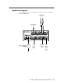
Application Diagram
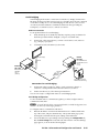
The following figure shows an example of types of devices that are connected to
some of the IPL’s ports.
IR Emitters
(to IR-controllable
devices)
RS-232 Enabled
A/V Device
IR
RS-232
MAC: 00-05-A6-XX-XX-XX
S/N:
POWER
12V
500mA
MAX
COM1
TX RX RTS CTS
COM 2
TX RX
1
IR
RELAY
1
2
2
S G S G
LAN
1
INPUT
2 3 4
COM 3
TX RX
3
IR
RELAY
4
3
4
S G S G
Ethernet
Extron TLP
Touchpanel
TCP/IP
Network
IR
Switch,
Sensor, or
Contact
Closure
Device
A/V Device’s
Room
Hardwired
Control
IR Control Equipment
Port
(screen
control,
projector
lift, lights)
PC
IPL 250 • Hardware Features and Installation
2-11
Hardware Features and Installation, cont’d
2-12
IPL 250 • Hardware Features and Installation
IPL 250
3
Chapter Three
Software-based Configuration
and Control
Configuration and Control: an Overview
The Basic Setup Steps: a Guide to this Chapter and Other Resources
Communicating with the IPL
Configuring the IPL for Network Communication
Global Configurator Software for Windows®
Advanced Configuration
Controlling an IPL250
Customizing the IPL’s Control Web Pages
Software-based Configuration and Control
Configuration and Control: an Overview
An IPL 250 must be configured before use in order to recognize and accept
commands and pass them on to the controlled devices. It can be configured and
controlled via a host computer attached to the LAN (local area network) port. See
chapter 2 for details about the port and cabling.
• The primary means for configuring the controller is by using the Extron Global
Configurator (GC) software. This method requires a properly configured PC with
Windows® 2000, Windows XP, or a higher version of Windows installed. Global
Configurator generates GlobalViewer® Web pages that are uploaded to the IPL and
can be used to control the unit and make adjustments to its settings.
N Microsoft® Internet Explorer® is currently the only Web browser that fully
supports GlobalViewer pages.
• Alternatively the default Web pages embedded within the IPL 250 provide
a means to perform some setup, adjustment, and control via a Web browser
(Internet Explorer version 5.5+, or Mozilla® Firefox® version 1.0+) from any type
of network-enabled computer.
• The third way to control and configure the controller is by using Simple
Instruction Set (SIS™) commands via Telnet, a Web browser, or RS‑232. SIS
commands are discussed in detail in chapter 4.
The Basic Setup Steps:
a Guide to this Chapter and Other Resources
N Setup/configuration may be performed away from the job site.
1 Configure the IPL for network communication. See “Configuring the Unit
for Network Communication” on page 3‑3.
2 Download or install Global Configurator and other Extron software
(IR Learner, Firmware Loader, GUI Configurator) and device drivers. See
chapter 1 of the IPL 250 Setup Guide, the software disk that was shipped with
the unit, and the Extron Web site for instructions.
N The IPL 250 Series Setup Guide is shipped with the unit. It is also available
as a PDF file on the Extron Web site (www.extron.com). The disk included with the
unit contains software, device drivers, a PDF file of the full reference manual, and
additional documentation available when the unit was shipped. The setup guide
outlines most of the common tasks required to set up an IPL.
3 Create a Global Configurator project and configure basic settings and
functions. See chapter 3 of the setup guide or see the Global Configurator Help
file for step-by-step procedures.
4 Configure additional or advanced functions, if desired. See the Global
Configurator Help file. For information on IR learning, read the IR Learner Help
file. If Extron TouchLink (TLP Series) touchpanels will be part of the system,
you will also need to use GUI Configurator to design and set up the interface
for the touchpanels, preferably before completing the IPL’s configuration.
5 Save and upload the configuration to the IPL. See the IPL 250 Setup Guide,
chapter 3.
6 Control the IPL and devices connected to it by using the IPL’s embedded
Web pages, its GlobalViewer (GV) Web pages, or a fully configured TLP
touchpanel. See “Controlling an IPL 250” later in this chapter.
3-2
IPL 250 • Software-based Configuration and Control
Communicating with the IPL
To communicate with the IPL 250, you must power on the IPL and the PC you will
use to configure it, and connect the two devices for IP (network) communication.
• Power: see chapter 2 for wiring instructions. It is best to power the IPL using the
12 VDC external power supply that is shipped with the unit.
• Communication: to connect the IPL to a network or to connect it directly to
the PC using a serial cable, see page 2‑6 or page 2‑7 of this manual for wiring
instructions. See “Configuring the IPL for Network Communication,“ below to
set the unit up to talk with the PC.
Configuring the IPL for Network Communication
To function together, both the PC and the IPL 250 must be configured correctly. The
PC must be network-capable with the proper protocols, and the IPL must be set up
so it can be connected to a LAN or other network.
When you power on the IPL for the first time, you have a choice of several ways to
set up the IP address:
• Use the Global Configurator software via the LAN connector.
• Use the ARP (address resolution protocol) command via the LAN connector.
• Use a Web browser via the LAN connector.
• Use SIS commands via Telnet and the LAN connector.
If you use a Web browser or Telnet the first time you connect a PC to an IPL via IP,
you may need to temporarily change the PC’s IP settings in order to communicate
with the controller. See “Setting up the PC for IP communication with an IPL” later
in this chapter. Then you must change the controller’s default settings (IP address,
subnet mask, and [optional] administrator name and password) in order to use the
unit on an intranet (LAN) or on the Internet. After you have set up the IPL 250 for
network communication, you can reset the PC to its original network configuration.
IPL 250’s LAN port defaults:
• IPL’s IP address: 192.168.254.254
• Gateway’s IP address: 0.0.0.0
• Subnet mask: 255.255.0.0
• DHCP: off
• Link speed and duplex level: autodetected
N Both the computer and the IPL must be connected to the same subnet on a LAN
(using a straight-through cable). Alternatively, you can use a crossover Ethernet
cable to connect the controller directly to your computer’s Ethernet card.
The following instructions assume that you have already connected the PC to the
IPL’s LAN port and powered on the controller and the PC.
Configuring the IPL for network use via Global Configurator
You can configure the controller’s IP address via an IP/Ethernet connection using
the Extron Global Configurator (GC) software. Read the Global Configurator help
file for basic information on using Global Configurator software and setting up a
project. Also read the IPL 250 Setup Guide for step-by-step instructions of how to
use GC to set up the IPL’s IP address.
IPL 250 • Software-based Configuration and Control
3-3
Software-based Configuration and Control, cont’d
Configuring the IPL for network use via the ARP command
The ARP (address resolution protocol) command tells your computer to associate
the IPL 250’s MAC (media access control) address with the assigned IP address.
You must then use the ping utility to access the controller, at which point the
controller’s IP address is reconfigured.
Use ARP to configure the IP address as follows:
1. Obtain a valid IP address for the IPL 250 from your network administrator.
2. Obtain the IPL’s MAC address (UID #) from the label on its rear panel. The
MAC address should have this format: 00-05-A6-xx-xx-xx.
3. If the IPL has never been configured and is still set for factory defaults, go to
step 4. If not, perform a Mode 4 system reset. For detailed information on
reset modes, see “Resetting the Unit” in chapter 2, “Installation”.
C
The IPL must be configured with the factory default IP address
(192.168.254.254) before the ARP command is executed, as described below.
4. At the PC, access the MS-DOS command prompt, then enter the arp –s
command. Type in the desired new IP address for the unit and the unit’s
MAC address. For example:
arp –s 10.13.197.7 00-05-A6-03-69-B0
N The MAC address is listed on the rear panel.
3-4
After the arp -s command is issued, the controller changes to the new
address and starts responding to the ping requests, as described in the next
step.
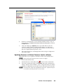
5. Execute a ping command by entering “ping” followed by a space and the new
IP address at the command prompt. For example:
ping 10.13.197.7
You must ping the IPL 250 in order for the IP address change to take place.
The response should show the new IP address, as shown in the following
picture.
IPL 250 • Software-based Configuration and Control
You can reconnect using either Telnet or a Web browser to verify that the
update was successful.
6.
After verifying that the IP address change was successful, enter and issue the
arp –d command at the DOS prompt. For example:
arp –d 10.13.197.7 removes 10.13.197.7 from the ARP table
or
arp –d* removes all static IP addresses from the ARP table.
Configuring the IPL for network use via a Web browser
The default Web pages that are preloaded on the IPL 250 are compatible with
popular Web browsers such as Microsoft Internet Explorer (version 5.5 or higher)
or Mozilla Firefox (version 1.0 or higher). However, the IPL and the PC must both
be part of the same subnet before they can communicate via the LAN port. You
must change the PC’s IP address to one that is on the same subnet as the default IP
address of the IPL 250 (192.168.254.254).
N This method requires a crossover cable. See page 2‑7 for cabling details.
N Make a note of the host PC's TCP/IP configuration before changing its IP
address and make sure the PC and IPL 250 are on the same subnet.
1.
Temporarily change the host PC’s IP address. See “Setting up the PC for
IP communication with an IPL 250” later in this chapter for step-by-step
instructions.
2. Obtain a valid IP address for the controller from your network administrator.
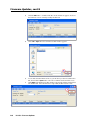
3. Launch the Web browser on the connected PC (for which you set up the
network configuration earlier), and enter http://192.168.254.254/ in
the address box. The IPL 250’s default Web page is displayed.
IPL 250 • Software-based Configuration and Control
3-5
Software-based Configuration and Control, cont’d
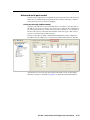
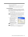
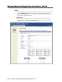
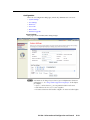
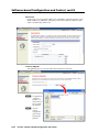
4.
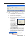
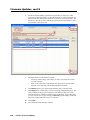
Select the Configuration tab, then select System Settings from the menu on
the left of the screen. A Web page appears. The top part of a typical screen is
shown in the following picture.
5.
Set the IPL for the new IP address using either step 5a or step 5b.
5a. Enter the new IP address for the IPL 250, the corresponding subnet
mask, and the gateway address. IP addresses and subnet masks
follow standard naming and numbering conventions. The IP network
administrator should provide the IP addresses and subnet mask to be
used with this controller.
5b. Select DHCP On.
6.
Click Submit. It takes a minute or more for the controller to store the new
settings. Once the controller’s IP address is changed, you lose communication
with the controller.
7.
Close the browser.
8.
After changing the controller’s IP settings, change your PC’s TCP/IP settings
back to their original configuration.
Configuring the IPL for network use via SIS™ commands and
Telnet
The IPL and the PC must both be part of the same subnet before they can
communicate via the LAN port. You must change the PC’s IP address to one that is
on the same subnet as the default IP address of the IPL 250 (192.168.254.254).
N This method requires connecting the IPL to the PC’s LAN port using a crossover
network cable. See page 2-6 for cabling details.
N Make a note of the host PC's TCP/IP configuration before changing its IP
address and make sure the PC and IPL are on the same subnet.
1.
Temporarily change the host PC’s IP address. See “Setting up the PC for
IP communication with an IPL 250” on the next page for step-by-step
instructions.
2. Start Telnet on the PC
a.
Click the Start menu and select Run. The Run dialog box appears.
b. Type telnet, a space, and the default IP address (192.168.254.254) into
the Open area, and click OK.
3-6
IPL 250 • Software-based Configuration and Control
3.
4.
Set the IPL for the new IP address by doing one of the following.
•
Enter SIS command E X1$ CI}, where X1$ is the new IP address (see
chapter 4, “SIS™ Programming and Control”) to set the IP address.
•
Enter SIS command 1DH} to enable DHCP.
After changing the controller’s IP address, change your PC’s TCP/IP settings
back to their original configuration.
Setting up the PC for IP communication with an IPL 250
You need a Windows-based (Windows 2000, XP, or higher) PC equipped with an
operating network adapter. For your PC to work with Extron Ethernet-controlled
products, the TCP/IP protocol must be installed and properly configured.
When setting up the IPL for network communication via a Web browser or Telnet
connection, you must change the IP address of the PC to one that is on the same
subnet as the IPL.
If you use an existing Ethernet LAN intranet, your network administrator can
provide you with a unique IP address for the controller or confirm whether you
need to set up the IPL 250 for DHCP (Dynamic Host Configuration Protocol) to
have an address assigned automatically when you sign on.
1.
Open the Network Connections page as follows:
•
Locate and right-click on My
Network Places on the Windows
(2000, XP, or higher) desktop,
then click on Properties.
or
•
Click on the Start menu,
click on Settings (if needed),
click on Control Panel to open the Control Panel window,
double-click on Network and Dial-up Connections (Windows 2000) or
Network Connections (Windows XP, shown below).
IPL 250 • Software-based Configuration and Control
3-7
Software-based Configuration and Control, cont’d
2.
Right-click on Local Area Connection, then select Properties.
3.
Select Internet Protocol (TCP/IP)
and click on the Properties button
(shown at right). If Internet Protocol
(TCP/IP) is not on the list, it must be
added (installed). Refer to the
Microsoft Windows user’s manual or
the Windows online help system for
information on how to install the
TCP/IP protocol.
4.
Write down the PC’s current IP
address and subnet mask below.
If your PC is set to “Obtain an IP
address automatically,” make a note
of that, instead. You will need to
restore these settings to the PC later.
IP address:
.
.
.
.
.
.
Subnet mask:
5.
.
.
Change the PC’s IP address so it can communicate with the IPL 250 and
change the controller’s IP settings.
a.
Click the Use the following IP address button.
b. Enter the following values, as shown in the following picture:
3-8
IP address: 192.168.254.253
Subnet mask: 255.255.0.0
Default gateway:blank or 0.0.0.0
IPL 250 • Software-based Configuration and Control
c.
6.
Click the OK button to save the changes and exit the network setup.
Reboot the PC, if required, for the changes to become effective.
Plug one end of a Category 5 network/Ethernet crossover cable into the IPL’s
Ethernet (LAN) connector. See chapter 2 for RJ‑45 LAN connector wiring.
Plug the other end of the Ethernet cable into the Ethernet port on the PC.
N If a network hub or switch is used between the PC and the IPL, use a straightthrough CAT 5 cable instead of a crossover cable. See page 2‑6.
7.
Set up the IPL’s IP address using a Web browser, or SIS commands as
described earlier in this chapter.
8.
Restore the PC’s previous IP configuration by following steps 1, 2, 3, and 5 but
using the PC’s original IP address settings you wrote down in step 4.
Global Configurator Software for Windows®
The included Extron Global Configurator (GC) program for Windows offers the
most complete way to configure and customize the controller via either RS‑232 or IP
connection. GC provides the ability to generate a Web browser-based GlobalViewer®
(GV) application and Web pages for each IP Link-based device (IPL 250, IP Link
interface, System 5 IP, MLC 226 IP, MLC 104 IP Plus, or other Extron device) on a
network. Once an IPL 250 is configured, its GlobalViewer Web pages allow the user
to manage, monitor, and control the IPL and the devices connected to it.
Global Configurator offers the best and easiest way to configure the IPL. Other
setup options include using SIS commands and the factory-embedded Web pages,
but many setup features are available only via Global Configurator. GC includes
some functions found on the controller’s embedded Web pages and many additional
features that are available only through the software.
IPL 250 • Software-based Configuration and Control
3-9
Software-based Configuration and Control, cont’d
Downloading the software and getting started
Global Configurator software is included with the controller. Global Configurator
software updates and a large variety of device drivers can be downloaded at no
charge from the Extron Web site (http://www.extron.com).
N Device drivers (for controlling projectors, VCRs, DVD players, etc.) can be
used by other Extron IP Link products, so they may be listed on the Extron Web
site as an IP Link driver package. You may also want to download the optional
IR Learner™, a free software utility for capturing infrared codes from a handheld
IR remote control to create custom drivers for operating IR-controlled devices
like the IPL that use IP Link and GlobalViewer.
N Do not change the directory or the name of the directory where the software files
are installed by default.
Refer to the IPL 250 Series Setup Guide for specific information on how to download
the software. Refer to that guide and to the Global Configurator Help file for details
and step-by-step procedures on how to start a GC project and perform basic setup
tasks for an IPL. Both the setup guide and the help file contain instructions on how
to set the IP address, gateway IP address, subnet mask, mail server IP address,
domain name, Telnet port, Web port, SMTP username, and SMTP password so
that the IPL 250 is able to communicate with the network. Obtain these parameters
from your network administrator and set them before continuing.
PC system requirements
For the IPL, Global Configurator
The IPL 250 and Global Configurator have the following hardware and software
requirements:
• Intel® Pentium® III 1 GHz processor
• Microsoft Windows operating system
○ Windows 2000 service pack 4, or
○ Windows XP service pack 2, or
○ a later version of Windows
C
Do not run this software on a PC that uses an earlier version of Windows.
• Microsoft Internet Explorer 6.0 with ActiveX® enabled
• Microsoft Windows Script 5.6
• 512 MB of RAM
• 50 MB of available hard disk space
• A network connection with a minimum data transfer rate of 10 Mbps (100 Mbps
is recommended)
N The IPL 250 requires GC version 3.0 or higher.
For a system that includes TouchLink touchpanels and GUI Configurator
If you use the IPL 250 with Extron TLP Series touchpanels, you will also need the
Extron GUI Configurator software to set up the panels’ user interface controls. GUI
Configurator has the same requirements as Global Configurator 3.0 and higher.
Using Global Configurator: helpful tips
Resources and notes
• The Global Configurator Help file provides information on settings and how to use
the Global Configurator program, itself.
3-10
IPL 250 • Software-based Configuration and Control
• The IPL 250 Setup Guide, which is shipped with the unit, and the help file
included with the software cover basic setup steps. They include instructions
and examples on how to use the basic tabs in GC.
• See the front and rear panel features sections in chapter 2 of this manual for
features and settings for the ports you will configure in GC.
• If you will configure the IPL at the installation site, Extron recommends using the
driver subscription function within Global Configurator to download drivers for
all manufacturer and device types before you go out into the field.
• The Global Configurator project file (*.gc2 or *.gcz) contains configuration settings
and it can be saved to a directory or folder for backup or for installation on
another IPL 250 controller. Saving a configuration is recommended before you
perform a firmware upgrade.
• Global Configurator 3 is capable of loading all GC2 project files from GC version
2.0.3.3 and up. GCZ files can be opened by clicking File > Open, by clicking the
toolbar icon, or by double-clicking on the GCZ file. GC2 and GCC files must be
imported, however.
• The IPL can be set up to allow configuration access to administrators only to
prevent other users from making changes to the settings, events, and drivers. If
an administrator password is set for the controller, non-administrator users can
select inputs, adjust output volume, and trigger some other device commands
from the GlobalViewer Control pages but are prevented from making any other
changes using GlobalViewer Web pages.
• IP addresses, subnet mask, and e-mail addresses follow standard naming and
numbering protocol. The network administrator provides the IP addresses and
subnet mask to be used with this controller.
• The unit name is any name (for example, Room107-ipl250, Lab1234control,
ConfRmSystem) that you want to use to label a specific IPL 250 unit. The default
is a combination of the product name and part of the hardware address. This can
be changed to your choice of alphanumeric characters and hyphens (-).
• Spaces are not permitted within a unit’s name.
• Underscores (_) are not permitted.
• Valid characters are A-Z, a-z, 0-9, and - (hyphen).
• The name cannot start with a number or a hyphen, and it cannot end with a
hyphen.
• Maximum name length is 24 characters.
A brief guide to Global Configurator’s tabs
In the upper right side of the GC window are several tabs that divide the program
into groups of functions you can view and configure. The left three, IP Link
Settings, Schedule, and Monitor, are displayed for all IP Link-enabled products.
Tabs to the right of those three vary in quantity, type, and layout, depending on the
product being configured. The figure below shows tabs that may be available when
you configure an IPL 250.
To learn about the functions available on each of these tabs, look in the Global
Configurator Help file. In the contents pane on the left, click on “Reference
IPL 250 • Software-based Configuration and Control
3-11
Software-based Configuration and Control, cont’d
Information”, click “Global Configurator Window”, then click on the name of the
tab you want to know more about.
Advanced Configuration
IR learning to create customized IR driver files
If you do not find a driver on the Extron Web site for the device you plan to
use, you can create your own IR driver file. Extron IR Learner™ software lets
you create a customized driver file of IR commands that can be used with the
Global Configurator software for port setup and button configuration. Visit
http://www.extron.com to download IR Learner and install it on your PC.
Once IR Learner is installed on the PC, you can start the program directly
by double-clicking the IR Learner icon, shown at right.
Or, you can select Run IR Learner from Global Configurator’s Tools
menu, as shown at right. The IR
Learner utility opens in a new window.
Refer to the IR Learner Help file for
instructions on how to create the driver
file. During IR command capture, hold
the projector or other device’s remote facing the IPL’s IR learning receiver within
the angles and distance range shown in the figure on page 2-3.
N The IPL 250 requires IR Learner version 1.23 or higher.
Printing a wiring block diagram or a GUI configuration report
Once you have configured a system using Global Configurator, you can generate
and print a simple block diagram of what products to wire to which of the IPL 250’s
ports. The diagram includes model names and the type of communication (IR or
RS‑232) configured for each port. Read the Global Configurator Help file’s “Reference
Information” section about the File menu for details.
N This procedure requires Microsoft Word software. The installer or user must
provide that software. It is not an Extron product.
Procedure overview:
1.
In Global Configurator, click on the File drop-down menu and select Print
and then Wiring Diagrams/GUI Configuration Report.
2.
In the Print Wiring Diagrams/GUI Configuration Report window, select the
devices to include in the diagram.
3.
Click the Print Wiring Diagrams button or the Print GUI Report button. GC
processes the information about the selected device(s), generates a document
containing the wiring diagram, and opens that document in Word.
4.
Print the diagram(s), save the file(s), if desired and exit Word.
5.
Close the Global Configurator Print Wiring Diagrams/GUI Configuration
Report window.
Updating firmware
If the need arises, you can replace the IPL’s firmware without opening the unit or
changing firmware chips. See appendix B, “Firmware Updates”, for instructions on
how to update the controller’s firmware.
N Save the existing configuration project before replacing the firmware.
3-12
IPL 250 • Software-based Configuration and Control
Advanced serial port control
If serial setup configurations are required, the following options provide advanced
methods for communicating serially with the IPL: serial pass-through (or redirect
mode), direct port access, and serial bridging.
Serial pass-through (redirect mode)
Serial pass-through allows serial commands from a controller to “pass through” an
IPL 250 on route to an A/V device. Any serial port on an IPL can be configured as a
pass-through connection to another serial port on the same device. For example, an
RS-232 control device connected to the IPL 250’s COM1 serial port could control a
projector connected to the COM2 serial port.
Serial pass-through is enabled or disabled through the IPL’s COM Configuration
tab within Global Configurator, as shown below and described in the GC help file.
Advanced users can use the pass-through SIS command as well. See the Simple
Instruction Set (SIS™) commands in chapter 4 for detailed command descriptions.
IPL 250 • Software-based Configuration and Control
3-13
Software-based Configuration and Control, cont’d
Direct port access (ports 2001 through 2003)
Direct port access allows a direct, one-to-one connection to any one of the IPL’s
serial ports using a TCP/IP connection. When a TCP session is initiated to a COM
port, all data sent and received passes directly to and from that port without any
processing. Set serial port parameters (baud rate, parity, etc.) within the IPL prior
to using direct access.
N The reserved TCP port numbers (2001-2003) are assigned by default as follows:
2001 = COM1
2002 = COM2
2003 = COM3
You can use SIS commands to assign a different port number to any of these
serial ports, if needed.
To initiate direct port access using Extron DataViewer software:
1.
Connect the IPL 250 to a network.
2.
If necessary, use GC, embedded Web pages, or SIS commands to set set serial
port parameters (baud rate, parity, etc.) for the IPL 250 COM port to be used.
3.
Launch the Extron DataViewer program.
4.
Click File > Connect to open the Communication Setup dialog box.
5.
Click the TCP/IP tab.
6.
Complete the fields with the IP address of the IPL 250 and the TCP/IP port
number (2001, 2002, or 2003) of the COM port (on that same IPL unit) that will
be used, as shown below.
N A password is not required for direct port access.
RS-232 enabled
A/V Device
2001
RS-232
MAC: 00-05-A6-XX-XX-XX
S/N:
POWER
12V
500mA
MAX
COM1
TX RX RTS CTS
COM 2
TX RX
1
2002
S
LAN
1
INPUT
2 3 4
COM 3
TX RX
3
2003
S
Ethernet
PC
TCP/IP
Network
DataViewer Communication Setup dialog box and direct access wiring
7.
Click OK. The DataViewer commands window opens.
8.
Type serial commands into the Commands area in the left of the window to
send serial commands directly through the selected COM port to the attached
A/V device.
9.
To end the direct access session, close DataViewer.
N You can force the direct access session closed by logging on to the IPL 250 as an
administrator and entering “EscX!*0CD}”, where X! is the selected COM port.
3-14
IPL 250 • Software-based Configuration and Control
Serial bridging
Serial bridging mode creates a virtual serial connection (a “bridge”) between two
IPL units allowing serial data to be passed over a shared LAN to devices connected
via the IPLs’ COM ports. To use serial bridging, two IPL devices (one local and
one remote) must be enabled to communicate with each other, providing PC,
touchpanel, or controller access to a remote A/V device.
Hardware connection
To set up the hardware for serial bridging:
1.
Verify that the protocol (baud rate, data bits, stop bits, parity) is identical for
both serial ports that will be “bridged” (one port on each IPL unit).
2.
For IPL unit 1 (the remote device), connect a serial cable to an A/V device
(e.g., a display or projector).
3.
Connect that same remote IPL (1) to the LAN.
Extron
IPL 250
Plasma Display
RE
1
RS-232
M
CO
TX
M
CO
1
M
CO
Extron
IPL T S4
12
30
# 09
UID
M
CO
RX
TX
1
T
PU 4
IN
3
2
1
2
G
S
S
G
RE
3
Y
LA 4
IR 4
M
CO
RX
TX
N
M
CO
S
M1 CT
CO RTS
RX
2
LA
2
05
Y
LA 2
IR 2
3
3
3
S
G
S
Unit 2
(Local)
G
WER
PO
V
12 A
0m
50
MAX
2
IP Link® Ethernet
Control Processor
N
LA
WER
PO
V
12 MAX
.5A
RS-232
Ethernet Control
Interface
Ethernet
Unit 1
(Remote)
Ethernet
TCP/IP
Network
Remote User Control &
Administrator Monitoring
Connections for serial bridging
4. For IPL unit 2 (the local device), make a serial connection to the PC or
controller or touchpanel that will control the remote A/V device.
5.
On the same device (2), follow the step 2 instructions.
You are now ready to configure IPL unit 2 for serial bridging mode.
Serial bridge configuration
To allow both IPL units to communicate together, you must configure unit 2 to
communicate with unit 1.
N If a serial (RS-232) driver was previously loaded (via Global Configurator) onto
the IPL unit, serial bridging disables it.
To configure unit 2 to communicate with unit 1:
1.
Enter the IP address of unit 2 in the Internet browser’s Address field at the
top of the screen, and press the Enter key. The System Status page opens,
showing the current IP and serial port settings of IPL 250 unit 2.
2.
Access the Web server port setting screen by clicking the Configuration tab,
then the Port Settings link on the left side of the window. The Port Settings
page appears, as shown in the following figure.
IPL 250 • Software-based Configuration and Control
3-15
Software-based Configuration and Control, cont’d
Unit 2’s Port Settings internal Web page
3.
Choose the serial port (on the local IPL 250, unit 2) that you wish to
communicate through.
4.
For Serial Bridging, click the On radio button to activate bridging mode.
5.
In the Remote IP Address field, type in the IP address of unit 1.
6.
In the Remote TCP Port field, type in the number (2001-2003) for the serial
port on unit 1 that is to be used in the virtual connection.
7. Click the Submit button.
The A/V device attached to remote unit 1 should now accept all serial commands
from your PC, touchpanel, or controller.
Saving and uploading the configuration
This is not an advanced configuration function, but when you finish creating the
configuration in Global Configurator, you must save the GC project and upload the
configuration to one or more IPL 250 units. See chapter 3 of the IPL 250 Setup Guide
(shipped with the IPL) or the Global Configurator Help file for instructions.
Controlling an IPL 250
You can control the IPL and devices connected to it by using a shared network and
one or more of the following tools:
3-16
IPL 250 • Software-based Configuration and Control
• the IPL’s factory-embedded Web pages
• the GlobalViewer (GV) Web pages that are created when you upload the GC
configuration to the IPL
• a TouchLink touchpanel with a customized graphical user interface (GUI),
provided that the TouchLink is included in the IPL 250’s configuration
Embedded Web pages
The IPL 250 features an embedded Web server, which includes factory-set Web
pages. These pages can be replaced with user-designed files, but the default Web
pages provide many basic features for monitoring, configuring, and controlling
the unit via a Web browser. This section provides an overview of these Web pages,
which provide some of the features of the configuration program.
To access the embedded Web pages,
1.
Launch a Web browser (Internet Explorer, Mozilla Firefox) on the connected
PC, enter the IPL’s IP address in the address field, and press the Enter key.
N After GlobalViewer Web pages have been uploaded to the IPL, the GV Web
pages open by default (instead of the factory-set Web pages) if you enter just
the IPL unit’s IP address (e.g. 10.13.197.7 or http://10.13.197.7).
To view the factory-set Web pages on a GV-enabled IPL unit, add
/nortxe_index.html after the IP address before pressing Enter. For
example, enter http://10.13.197.7/nortxe_index.html.
2.
In the Connect to <IP address> dialog
box, shown at right, enter the IPL’s IP
address or text of your choice in the
User Name field, type in the
administrator password in the
Password field, and click OK. The IPL’s
default Web page appears.
If the IPL has not already been
configured with a password, this
password dialog box does not appear;
the default Web page opens directly.
N Passwords must contain 4 to 12
alphanumeric characters. Symbols and spaces are not allowed and the passwords
are case sensitive.
N Administrators have access to all of the Web pages and are able to make
changes to settings. Users can access the System Status page only.
IPL 250 • Software-based Configuration and Control
3-17
Software-based Configuration and Control, cont’d
Status
The Status Web page provides only settings information. Changes must be made
via the Configuration Web page or via the Global Configurator software or SIS
programming. Personnel who have user access can view these pages but do not
have access to configuration pages.
System Status
The System Status page provides information about the IPL 250’s model, part
number, firmware level, port and IP settings, as shown in the following example.
This information is useful when troubleshooting.
3-18
IPL 250 • Software-based Configuration and Control
Configuration
There are six Configuration Web pages, which only administrators can access:
• System Settings
• Port Settings
• IR Drivers
• Passwords
• Email Alerts
• Firmware Upgrade
System Settings
This page is for IP and date/time setting changes.
N Unit Name can be changed to your choice of up to 24 alphanumeric characters
and hyphens (-). See “Using Global Configurator: helpful tips“ in this chapter
for examples.
• Spaces ( ) and underscores (_) are not permitted within a unit’s name.
• Valid characters are A-Z, a-z, 0-9, and - (hyphen).
• The name cannot start with a number or hyphen. It cannot end with a hyphen.
IPL 250 • Software-based Configuration and Control
3-19
Software-based Configuration and Control, cont’d
Port Settings
This page allows limited changes to serial (COM) port settings and to the on/off
status of each relay port.
3-20
IPL 250 • Software-based Configuration and Control
IR Drivers
Once the IPL 250 is configured and IR drivers have been uploaded to the unit and
linked to specific IR ports, you can view a list of the uploaded drivers in this page.
Click on the name of the driver file to switch to a view of the commands loaded for
that driver. Clicking on a command name makes the IPL send that command out
its linked IR port to the connected device.
Passwords
In the Passwords page you can change the administrator and/or user passwords.
N Passwords must contain 4 to 12 alphanumeric characters. Symbols and
spaces are not allowed and the passwords are case sensitive. A minimum of 4
characters are required when creating passwords via the Web pages. Also, a user
password cannot be assigned if an administrator password does not exist. And if
the administrator password is cleared, the user password is also cleared.
IPL 250 • Software-based Configuration and Control
3-21
Software-based Configuration and Control, cont’d
Email Alerts
In this page you can specify the Web server’s IP address and domain name, set up
SMTP verification credentials, and specify e-mail alert recipients’ addresses and
which e-mail file they will be sent.
Firmware Upgrade
Through this page you can locate and load new firmware to the unit.
N See appendix B,
“Firmware
Updates”, for
instructions on
how to update
the firmware.
N Save the
existing
configuration
project before
replacing the
firmware.
3-22
IPL 250 • Software-based Configuration and Control
File Management
This Web page allows you to sort by file type (see the Filter by File Extension dropdown box). Personnel with administrator access can view these pages and make
changes. Those with user-level privileges are not able to see this page. For an
explanation of file types see appendix A.
C
Files with the .cdc extension (___.cdc files) should NOT be deleted.
C
Event files (__.evt) should NOT be deleted. They are necessary for the
controller’s operation. Never delete the main event file (0.evt).
You can also view files in subfolders, including those containing GlobalViewer files
if they have been installed on the IPL 250. The following screen view shows an
example of the file management page for subfolders.
IPL 250 • Software-based Configuration and Control
3-23
Software-based Configuration and Control, cont’d
GlobalViewer® Web Pages
The IPL 250 can be used as part of a network of devices based on Extron IP
Link technology. Global Configurator (GC) is a Windows-based program used
for configuring and customizing the Web browser-based GlobalViewer (GV)
application for each IPL, System 5 IP, MLC, or other IP Link-based device on a
network. Once an IPL 250 is configured, its GlobalViewer Web pages allow the user
to manage, monitor, and control the IPL and the devices connected to it.
Refer to the Global Configurator help file and the IPL 250 Setup Guide for specific
information on how to use the software and perform basic setup tasks.
N To work with GlobalViewer Web pages, you must use Microsoft Internet
Explorer version 6.0 or higher with ActiveX enabled.
N If the IPL has been configured with passwords, the GlobalViewer Web pages are
password protected. Although default embedded Web pages are accessible via the
GlobalViewer Web pages, nonadministrators (people with only user access) are
able to access only the Status default Web page and some GlobalViewer Control
pages.
Four screens for the IPL are available via Global Viewer: Control, Monitor,
Schedule, and Info (
). Screens such
as Monitor and Schedule appear only for ports and controlled devices that have
been included in specific monitors or schedules you set up using GC. The Info
screen appears for the overall system, not for specific connected devices.
Read the Global Configurator Help file for details on each screen and how to use the
GlobalViewer pages.
3-24
IPL 250 • Software-based Configuration and Control
The following figures are examples of IPL 250 GlobalViewer pages.
A GlobalViewer Schedule page
A GlobalViewer Monitor page
IPL 250 • Software-based Configuration and Control
3-25
Software-based Configuration and Control, cont’d
A GlobalViewer overall system page
If a device has been set up with an IR or RS-232 driver, click on the device’s name
on the left side of the GlobalViewer window to open a Control page that shows the
available commands for the device. The following screen shot shows one example.
A GlobalViewer device control page
You can click the GlobalViewer’s on-screen buttons to send the corresponding
command from the IPL to that device.
3-26
IPL 250 • Software-based Configuration and Control
Controlling the IPL 250 with a Touchpanel
After both devices are configured, the IPL 250 can be controlled with an optional
Extron TLP touchpanel.
1.
Set up each touchpanel’s graphical user interface (GUI) by using the GUI
Configurator software. Refer to the GUI Configurator Help file for details.
2.
Connect the touchpanel(s) to the same network that the IPL 250 uses.
3.
While configuring the IPL in Global Configurator, add each TLP to the
Touchpanel ports. Connect to the TLPs and upload the GUI layout for each
panel. Refer to the Global Configurator Help file for the procedure.
4.
Use GC to configure the panel’s on-screen and hardware buttons.
5.
Upload the configuration to the IPL.
6.
Test the system by pressing the touchpanel’s buttons (or pressing/clicking
the touchpanel’s virtual buttons in the IPL 250’s GlobalViewer Web page) and
observing how the IPL and the other devices in the system react.
•
If everything works as it is supposed to, you may disconnect the PC
or laptop from the IPL or the network and use just the touchpanels to
control the IPL.
•
If the system components do not respond properly when you test the
touchpanel, check and adjust the IPL’s configuration using GC, then
upload the revised configuration.
IPL 250 • Software-based Configuration and Control
3-27
Software-based Configuration and Control, cont’d
Customizing the IPL’s Control Web Pages
Extron offers Web page templates that can be customized using standard HTML
editing tools or third-party software such as Microsoft® FrontPage or Adobe®
Dreamweaver® to provide a different interface to the user while still using
GlobalViewer functions. An experienced Web developer can add images, modify
text, and change background colors to create a look and feel that reflects your brand
or your user’s specific requirements. For example, a university with dozens of
devices and rooms to control may wish to create customized Web pages with the
university’s school colors and logo. End users can control the system using these
customized pages instead of the standard GV pages.
Alternatively, Extron can create a customized GUI for you to upload to each IPL 250
in the system. End users can view the Web pages of this customized GUI while
administrators and installers still have access to the factory-set Web pages and the
standard GV Web pages in addition to the customized ones.
For a small, one-time fee, Extron will turn the following items into files ready to
upload to the unit:
• your GlobalViewer project file containing system configuration details
• your choice of available color schemes
• your choice of labels for panel buttons
• a company or institution logo
These customized Web pages, whether created by Extron or modified by an outside
HTML developer from Extron-supplied templates used in the system.
Visit the Extron Web site (http://www.extron.com/product/customgui.aspx) or contact an
Extron customer support representative for more information on this service and on
available template options .
3-28
IPL 250 • Software-based Configuration and Control
Troubleshooting
Turn on the input devices (DVD players, VCRs, PCs, and other sources), output
devices (display screens, projectors), the IPL 250, and the PC and touchpanel.
Touch a configured button on the touchpanel or (via PC) click a control button on
the IPL’s embedded Control Web pages.
If an input or output A/V device cannot be remotely controlled (does not respond
as expected), check the following:
Power connections
1.
Ensure that all devices are plugged in.
2.
Make sure that each device is receiving power. The IPL’s front panel Power
LED lights if the device is receiving power.
Data connections
1.
Check the cabling connections and make adjustments as needed. The Link
LEDs on the IPL T and on the touchpanel or PC should be lit solid green if
a network connection is detected. If these LEDs are not lit, either the cable
is faulty or not plugged in, or the wrong type of cable is being used (see
chapter 2, “Hardware Features and Installation”).
2.
Try to “ping” the unit by entering ping 192.168.254.254 at the DOS
command prompt, or use the IP or Web address provided to you by your
system administrator. If you get no response:
a.
Make sure your unit is using the appropriate subnet mask (check with
your system administrator).
b. Make sure your PC and network do not have a software firewall program
that might block the IP address of the IPL unit.
3.
If contact is established with the unit, but the unit’s Web pages cannot be
accessed by your Web browser, verify (in the Options or Preferences menu)
that your Web browser is configured for direct network connection and is not
set up to use a proxy server.
Device control connections and configuration
1.
Verify that ports are wired correctly and that ground (earthing) wires are
connected to the proper pins on the IPL and, if applicable, on the controlled
device.
2.
Ensure that each IR emitter head is placed adjacent to or directly over the
controlled device’s IR pickup window.
3.
Verify that the appropriate drivers were used while creating the GC
configuration file and that the correct commands and signal types (IR or
RS‑232) are associated with the correct ports on the IPL and the other devices.
If you are still experiencing problems, call the Extron S3 Sales & Technical Support
Hotline or the Extron S3 Control Systems Support Hotline.
IPL 250 • Software-based Configuration and Control
3-29
Software-based Configuration and Control, cont’d
3-30
IPL 250 • Software-based Configuration and Control
IPL 250
4
Chapter Four
SIS™ Programming and Control
Host-to-IPL Communications
Commands and Reponses
SIS™ Programming and Control
The IPL 250 can be remotely controlled via a host computer, touchpanel, or other
device (such as a control system) attached to a shared network.
The IPL must be configured before use. As shipped the controller/processor
cannot control any other devices or interact with a touchpanel before being
configured. Set up the IPL or control it by using Extron Simple Instruction Set
(SIS™) commands or Extron Global Configurator software (version 3.0 or higher),
via Ethernet LAN connection. See chapter 2 for pin assignments and protocol. For
information on the software and the embedded Web pages, see chapter 3 and refer
to the software’s help files.
IPL 250 LAN port defaults:
• IPL’s IP address: 192.168.254.254
• gateway’s IP address: 0.0.0.0
• subnet mask: 255.255.0.0
• DHCP: off
Host-to-IPL Communications
SIS commands consist of one or more characters per field. No special characters
are required to begin or end a command sequence. When the IPL determines that
a command is valid, it executes the command and sends a response to the host
device. All responses from the IPL to the host end with a carriage return and a line
feed (CR/LF = ]), which signals the end of the response character string. A string
is one or more characters.
IPL 250-initiated messages
If you are communicating with the IPL via a verbose Telnet connection, when a
local event such as a selection via a touchpanel takes place, the IPL responds by
sending a message to the host. No response is required from the host. The IPLinitiated messages are listed here).
(c) Copyright 2009, Extron Electronics, IPL 250, Vx.xx, 60-1026-81]
Day, DD MMM YYYY HH:MM:SS]
Vx.xx is the firmware version number.
Example:
(c) Copyright 2009, Extron Electronics, IPL 250, V1.15, 60-1026-81
Wed, 29 Jul 2009 14:53:34
The IPL 250 sends the boot and copyright messages when you first open a Telnet
connection to the IPL. You can see the day of the week, date, and time if the unit is
connected via Telnet. If you use a Telnet connection, the copyright message, date,
and time may be followed by a password prompt.
Additional messages may be sent by the IPL in response to changes made through
the touchpanel and when scripts are executed during scheduled events.
Password information
The “]Password:” prompt requires a password (administrator level or user level)
followed by a carriage return. The prompt is repeated if the correct password is not
entered.
If the correct password is entered, the unit responds with
“]Login Administrator ]”, “******]Login Administrator]”, or
“]Login User]”, depending on the password entered. If passwords are the same
for both administrator and user, the unit defaults to administrator privileges.
4-2
IPL 250 • SIS Programming and Control
Error responses
When the IPL 250 receives a valid SIS command, it executes the command and
sends a response to the host device. If the IPL is unable to execute the command
because the command is invalid or it contains invalid parameters, it returns an
error response to the host.
The error response codes and their descriptions are as follows:
E10 – Invalid command
E12 – Invalid port number
E13 – Invalid value (the number is out of range/too large) or parameter
E14 – Not valid for this configuration
E17 – System timed out
E22 – Busy
E24 – Privilege violation
E25 – Device is not present
E26 – Maximum number of connections has been exceeded
E27 – Invalid event number
E28 – Bad filename or file not found
E31 – Attempt to break port pass-through when not set (A user or software
attempted to disable the port redirect feature when it wasn’t already set or active.)
Error response references
The following superscripted numbers are used within the command descriptions
on the following pages to identify commands that may respond as shown:
14
= Commands that give an E14 (not valid for this configuration) response if the
unit’s current configuration doesn’t support that command.
22
= Commands that yield an E22 (busy) response.
24
= Commands that give an E24 (privilege violation) response if you are not logged
in at the administrator level.
27
= Commands that may yield an E27 (invalid event number) response.
28
= Commands that may give an E28 (file not found) response.
Commands and Reponses
Using the command/response tables
The IPL 250 can be controlled via a Telnet (port 23) connection using ASCII commands,
or via a Web browser (port 80) connection using URL-encoded commands. The ASCII
and URL commands listed in the tables starting on page 4-8 perform the same
functions, but they are encoded differently to accommodate the requirements of each
port (Telnet or browser).
The ASCII to
hexadecimal (HEX)
conversion table
shown at right is for
use with the
command/response
tables.
Space
ASCII to Hex Conversion Table
•
ASCII to Hex conversion table
IPL 250 • SIS Programming and Control
4-3
SIS™ Programming and Control, cont’d
The command/response tables list valid ASCII command codes, the corresponding
URL (uniform resource locator) encoded (for Web browsers) command codes, the
IPL’s responses to the host, and a description of the command’s function or the
results of executing the command.
Entering SIS commands: helpful tips
• Upper and lower case characters may be used interchangeably in the command
field unless otherwise specified.
• Commands may be sent back-to-back without spaces (for example, 2!65V1Z).
• Numbers can be entered as 1, 2, or 3 digits, e.g., 8V = 08V = 008V.
• There are a few differences in how to enter the commands depending on whether
you are using Telnet or a Web browser.
When using these commands through a Web browser, the URL reference
is used to shorten the examples. “URL” refers to the full URL of the
control interface and Web page reference including all path information
(e.g., http://192.168.100.10/myform.htm).
To send any of the commands using a Web browser you must prefix them
with the full URL followed by ?cmd=.
For control via a Web browser, all non-alphanumeric characters must be
represented as the hexadecimal equivalent, %xx, where xx represents the
two-character hex byte. A comma (,), for example, would be represented
as %2C.
Characters such as %, +, and the space character ( ) must be encoded as
hex bytes, or they will be misinterpreted by the IPL. For example, the
ASCII command +V must be encoded as %2BV for Web browser use.
Some characters differ depending on the method you use to send the
commands:
Telnet
Web browser
Escape (hex 1B)
W [must not be hex encoded]
Carriage return (hex 0D)
Pipe character (|) [must not be hex encoded]
N
N
4-4
With Telnet you can use either an “Escape” (E) command or a “W”
command, and the carriage return or the pipe character. With the Web
browser, you are required to use a “W” command and the pipe character.
In either method, {Data} = data that will be directed to a specified port
and must be hex encoded if non-alphanumeric.
If you make adjustments, it will take up to 1 minute 40 seconds (100 seconds)
for the data in the IPL’s RAM to be saved to flash memory. Do not remove
power during that period.
IPL 250 • SIS Programming and Control
Symbol definitions
] =
} =
•
Carriage return (no line feed, hex 0D)
(for URL-encoded commands, use the
pipe character, | , instead)
= Space character
|
= Pipe (vertical bar) character
*
= Asterisk character (which is a command
character, not a variable)
E=
X!
Escape key (hex 1B)
(for URL-encoded commands, use W
instead of Esc)
= Specific port number or relay number (01-99)
Serial ports:
01 = COM1 port
02 = COM2 port
03 = COM3 port
Relay ports:
01 = Relay port 1
02 = Relay port 2
03 = Relay port 3
04 = Relay port 4
IR ports:
01 = IR port 1
02 = IR port 2
03 = IR port 3
04 = IR port 4
00 = reserved or all ports
N Port numbers are two ASCII characters
(2 bytes). For example, port 1 is represented as
01 (hex 30 31).
X@
= Command data section.
N For Web encoding only: data will be directed
to the specified port and must be encoded (URL
encoding) if it is non-alphanumeric. Change
any non-alphanumeric character (%, +,
|, }, etc.) within the data section into the
corresponding hexadecimal equivalent, %xx,
where xx represents the two-character hex byte.
For example, a space (hex: 20) would be encoded
as %20 (hex: 25 32 30) and a plus sign (hex: 2B)
would be encoded as %2B or hex 25 32 42.
X#
sign/hyphen (-). No blank or space
characters are permitted as part of a name.
No distinction is made between upper and
lower case. The first character must be
a letter. The last character must not be a
minus sign/hyphen.
CR/LF (carriage return/line feed) (hex 0D 0A)
= Greenwich Mean Time (GMT) offset value
(‑12.00 to +14.00) represents the time
difference in hours and minutes
(+/-hh:mm) relative to Greenwich,
England. The leading zero is optional.
For example, 5:30 = 05:30. Do not use a
plus (+) sign if the GMT offset is positive.
X%
= On/off status
0 = off/disable (default for DHCP)
1 = on/enable
X^
= “Dirty” status:
0 = contents of RAM have been saved to
flash memory and it is ok to power off or
reset the unit
1 = RAM contents need to be saved to
flash memory
X1! = Version (typically listed to two decimal
places, e.g., x.xx)
X1@ = IPL 250’s name. The name is a text string
of up to 24 characters drawn from the
alphabet (A-Z), digits (0-9), and minus
X1# = Local date and time format
Set format (MM/DD/YY-HH:MM:SS).
Example: 01/18/05-10:54:00.
Read format (day of week, date month year
HH:MM:SS). Example: Tue, 3 Jul 2007
18:19:33.
X1$ = IP address (xxx.xxx.xxx.xxx). Leading zeros
in each of four fields are optional in
setting values, and they are suppressed in
returned values.
IPL 250’s default address: 192.168.254.254
Default broadcast address:
255.255.255.255.
X1% = E-mail domain name; for example, extron.com
X1& = Time in tens of milliseconds to wait until the
first response character is received via a
serial port before terminating the current
receive operation. (Default = 10 = 100
ms, max. = 32767.) The response includes
leading zeros.
N For commands that use both X1& and X2), both
variables must be zero or both must be non‑zero.
In the RS (send data) command, X1& may be
omitted as long as X2) is also missing.
X1* = Hardware (MAC) address (xx-xx-xx-xx-xxxx) (00-05-A6-xx-xx-xx) For the location
of this address, see h MAC address in
chapter 2.
X1( = Subnet mask (xxx.xxx.xxx.xxx). Leading
zeros are optional in setting values in each
of four fields, and they are suppressed in
returned values. Default = 255.255.0.0.
X2) = Time in tens of milliseconds to wait between
characters being received via a serial port
before terminating the current command
or receive operation. The response
includes leading zeros.
(Default = 2 = 20 ms, max. = 32767)
N For commands that use both X1& and X2), both
variables must be zero or both must be non-zero.
In the RS (send data) command, X1& may be
omitted as long as X2) is also missing.
X2! = Parameter (#L or #D) to set either the Length
of message to receive or the Delimiter
value. # = byte count (for L) or
# = a single ASCII character expressed in
decimal form (for D).
The parameter is case sensitive; you must
use capital D or capital L.
Byte count # can be from 0 to 32767,
default = 0.
The ASCII decimal # can be from 0 to
00255, default = 00000L.
Examples:
A 3-byte length = 3L.
A delimiter of ASCII 0A = 10D.
The response from the MLC includes
IPL 250 • SIS Programming and Control
4-5
SIS™ Programming and Control, cont’d
leading zeros.
X2@ = Verbose/response mode status:
0 = clear, default for Telnet connections
1 = verbose mode is on
2 = send tagged responses for queries
3 = verbose mode is on and tagged
responses are sent for queries
N If tagged responses are enabled, all read
commands return the constant string + the data
or value, the same as in responses for setting
a value. For example, for E CN }, the
response is Ipn• X1@ ] rather than just the
data (X1@ ]).
X2# = Priority status for receiving timeouts:
0 = use send data string command
parameters (0 = default)
1 = use configure receive timeout command
parameters
X2% = Baud rate: 300, 600, 1200, 1800, 2400, 3600,
4800, 7200, 9600 (default), 14400, 19200,
28800, 38400, 57600, or 115200
X2^ = Parity (only the first letter is needed):
O = odd
E = even
N = none (default)
M = mark
S = space
X2& = X2* = X2( = Data bits: 7, 8 (default = 8)
X3) = Flow control (only the first letter is needed):
H = hardware
S = software
N = none
Stop bits: 1, 2 (default = 1)
Serial port type:
0 = RS-232 (the only serial protocol
supported by the IPL 250)
X3! = Data pacing (time between bytes) in
miliseconds (0000 - 1000). 0000 (0 ms) is
the default.
X3# =
Password (minimum length = 4 characters,
maximum length = 12 characters)
No special characters are allowed: use
alphanumeric characters. Passwords are
case sensitive.
N A user password cannot be assigned if no
administrator password exists; the E14 error
code will be returned. If the administrator
password is cleared, then the user password is
also removed.
X3$ = 4-6
Daylight saving time (DST) is a regionspecific 1-hour offset that begins in spring
and ends in fall.
0 = off/ignore
1 = USA on – Starting in 2007, DST begins
on the second Sunday of March at 2 AM
and ends at 2 AM on the first Sunday
of November. For example, time in
California is GMT -8:00 from March to
November and GMT -7:00 from November
to March. However, DST should be
turned off in Hawaii, American Samoa,
Guam, Puerto Rico, the Virgin Islands,
the eastern time zone portion of the
state of Indiana, and the state of Arizona
(excluding the Navajo Nation).
2 = Europe on – begins on the last Sunday
IPL 250 • SIS Programming and Control
in March, ends on the last Sunday in
October. DST should be turned off for
Iceland.
X3% = Event number: 0 - 99
This is valid only while events are
running.
X3^ = Event buffer:
0 = receive
1 = user (absolute, unified)
2 = user (relative, data)
3 = NVRAM
X3& = Event buffer offset: 0 - [max. buffer size]
X3* = Event data buffer size (only the first letter is
needed):
b = bit
B = byte (8 bits)
S = short (16 bits)
L = long (32 bits)
N This parameter is case sensitive.
X3( = X4! =
Event data to write
X4@ =
Contact input state
0 = off (open)
1 = on (closed, shorted)
Password to display on screen (response to
password query or set). When the unit
connects to a host device via RS-232, the
password (X3#), itself, is the response.
When the connection is via IP, X4! is
4 asterisks (****) if a password has been
assigned, or it is an empty field ( ) if a
password hasn’t been assigned.
X4$ = Number of bytes to read (1 - 27)
X4% = E-mail event number or mailbox (1 - 64).
response includes leading zeros.
The
X4^ = E-mail recipient’s address
(e.g., [email protected]) for the person to
whom messages will be sent. The e-mail
address has a 31 character maximum.
X4& =
Name (for CR commands) or numeral (1 - 999,
for SM commands) of the e-mail file to be
sent
N E-mail files must have a file extension of .eml.
The first line of the file is the subject, the rest is
the body of the e-mail.
X4( =
Default name: a combination of the model
name and the last 3 pairs of the unit’s
MAC address (e.g., IPL-250-03-69-B0)
X5) = Redirection status:
0 = no redirection
1 - 3 = redirect serial port communication
from the specified port (1 = COM1, 2 =
COM2, or 3 = COM3) to allow a serial
pass-through mode (See “Serial passthrough (redirect mode)” in chapter 3.)
X5@ =
Connection’s security level:
0 = not logged in
11 = user
12 = administrator
The response includes leading zeros.
X5# =
Timeout period in tens of milliseconds for
serial data pass-through mode, after
which event data can be inserted into
the transmit buffer and the serial port is
released to another source
(Default = 10 = 100 ms, range = 1 - 32767.)
The response includes leading zeros.
X5$ = ASCII digit(s) representing the numeric value
of the data element read from the event
buffer (Leading zeros are suppressed.)
X5& =
IR playback file number (0 to 99) (no
extension). The response includes leading
zeros.
X5* = IR playback function number (1 to 137).
The response includes leading zeros. IR
function numbers 0 and 127 or higher can
return information only.
0 = return all data
129 = manufacturer
130 = model
131 = class
132 = remote
133 = creation date
134 = comments
137 = user file name (a descriptive name
the user/installer gave the file)
X5( = IR playback mode
0 = play once
1 = play continuously
The response includes leading zeros.
N Send the command again with mode =0 to stop
mode 1 playback.
X6# =
Pulse time in 20 ms increments. If this
parameter is missing or = 0, then pulse
length = default = 25 = 500 ms. 1 = 20 ms
(minimum pulse time) to 65535 =
1310700 ms (maximum pulse time).
X6( =
IP connection timeout period specified in
10‑second steps (1 - 65000, default =
30 = 300 seconds). If no data is received
during the specified period, the Ethernet
connection closes. Responses are returned
with leading zeros.
X7) =
The number (0 - 65535) to insert into an
email message if a ____.eml file has
an embedded server-side include
“<!--#echo var = “WCR|” -->”
(the E CR} command with no
parameters.) The numeral is a 16‑bit
number to be employed as the user
defines.
This is an optional parameter. Use 0 as a
placeholder if the optional X4& variable is
used but X7) is not needed.
Maximum = 65535.
X7# =
An e-mail account username of up to 31
characters. Do not use commas. This
parameter is optional during setup and is
used for SMTP authentication.
X7$ =
An e-mail account password (for SMTP
authentication) of up to 31 characters.
Do not use commas. This parameter is
optional during setup. If a password
is set, the response is not the actual
password characters but asterisks (****).
IPL 250 • SIS Programming and Control
4-7
4-8
(host to IPL)
ASCII (Telnet)
(host to IPL)
URL Encoded (Web)
(IPL to host)
Response
Additional description
IPL 250 • SIS Programming and Control
10
20
30
40
50
60
70
80
90
100
110
120
(
2
<
F
P
Z
d
n
x
LF
0
)
3
=
G
Q
[
e
o
y
1
space
*
4
>
H
R
\
f
p
z
2
!
+
5
?
I
S
]
g
q
{
CR
3
“
,
6
@
J
T
^
h
r
|
4
#
7
A
K
U
_
i
s
}
5
$
.
8
B
L
V
‘
j
t
~
6
Esc
%
/
9
C
M
W
a
k
u
Del
7
&
0
:
D
N
X
b
l
v
8
To find the decimal equivalent of the ASCII character, add the
row heading and column heading numbers together.
’
1
;
E
O
Y
c
m
w
9
ASCII (Character)
to Decimal
Conversion
ASCII to Decimal
Conversion
Table Table
LF = line feed
CR = carriage return (})
Esc = escape
Del = delete
ASCII/
Character
Decimal
N Use the ASCII to decimal table below to convert the byte count number for X2! when using a delimiter (D).
N The data string (X@) in this RS command is limited to 200 bytes.
response from command ]
W05%2A4%2A7%2A3L RS|<data>
N For Web encoding for X@, convert nonalphanumeric characters to hex numbers. A space (hex = 20) is encoded as %20.
A plus sign (hex = 2B) is encoded as %2B.
E 05*4*7*3L RS }<data>
Example: N * X1& * X2) * X2! is optional. X1& may be omitted only if X2) is also missing. If these three variables are not specified, the
default values are used. For this command, X1& and X2) must both a) equal zero or b) be nonzero, or c) both be omitted.
response from command]
W X! %2A X1& %2A X2) %2A X2! RS| X@
until receipt of the first response character
before terminating the current receive
operation (default = 10 = 100 ms, max. =
32767). The response includes leading zeros.
X2) = time in tens of milliseconds (ms) for
the IPL to wait between characters being
received via a serial port before terminating
the current receive operation (default = 2 =
20 ms, max. = 32767). The response includes
leading zeros.
X2! = #L or #D. The letter parameter is case
sensitive (requires a capital “D” or capital
“L”). The response includes leading zeros.
L = length of the message to be received.
D = delimiter value.
# = byte count (for L) or a single ASCII
character expressed in decimal form (for D).
Byte count # can be from 0 to 32767, default
= 0. The ASCII decimal delimiter # value
can be from 0 to 00255, default = 0L.
For #L, # is a regular ASCII (character)
numeral. If the length is 50 bytes, # = 50.
For #D, # can be any character(s) or number(s),
but it is translated into decimal format for use in
the command.
Examples: A 3-byte message length = 3L.
A delimiter of $ would be entered as 36D (36 is
the decimal equivalent of the dollar sign).
A delimiter of ASCII 0A = 10D (line feed).
X@ = command data section (< 200 bytes).
X1& = time in tens of ms for the IPL to wait
00 = reserved or all ports
Serial ports:
01 = COM1 port
02 = COM2 port
03 = COM3 port
These commands apply to any port that uses RS-232 communication: both 1-way (output) and 2-way (bidirectional) RS-232 communication.
Send data string
E X! * X1& * X2) * X2! RS} X@
X! = Specific port number (01-99):
Serial port configuration and use
Command
Command/response table for SIS commands
SIS™ Programming and Control, cont’d
IPL 250 • SIS Programming and Control
4-9
Configure receive timeout24
View serial port parameters
View flow control24
X3),X3! ]
X2%, X2^, X2&, X2( ]
W X! CF|
W X! CP|
E X! * X1& * X2) * X2# * X2! CE }
W X! %2A X1& %2A X2) %2A X2# %2A X2! CE|
Cpn X! •Cce X1& , X2) , X2# , X2! ]
E X! CF}
E X! CP}
Cpn X!•Cfl X3),X3! ]
X2( ]
Cpn X!•Cty X2( ]
Set the time to wait (X1& = waiting time in
tens of ms until receipt of the first response
character before terminating the receive
operation, X2) = waiting time in
tens of ms between characters before
terminating) and priority status
(X2#: 0 = default, use send data string
command parameters; 1 = use configure
receive timeout command parameters) for
port X!. X2! = #L or #D (see previous page).
The response includes leading zeros.
type the IPL supports)
X2( = serial port type = 0 = RS-232 (the only
(H = hardware, S = software, N = none)
X3! = data pacing in miliseconds (0000 - 1000)
X3) = flow control
The response is always 0] for the IPL 250.
N There is no other mode option (no
RS‑422, for example) for the IPL 250
E X! CY}
W X! CY|
E X! * X3),X3!CF}
W X! %2A X3)%2CX3!CF|
Configure flow control
W X! %2A X2( CY|
Cpn2•Ccp9600,N,8,1]
View mode
Example:
Configure serial port parameters24
X2( = serial port type = 0 = RS-232.
Additional description
E X! * X2(CY}
(IPL to host)
Response
Configure mode24
(host to IPL)
URL Encoded (Web)
X2% = baud rate (300-115200 baud, default =
9600 baud)
X2^ = parity (O = odd, E = even, N = none
[default], M = mark, S = space)
X2& = data bits (7 or 8)
X2* = stop bits (1 or 2)
Set port 2 for 9600 baud, no parity,
8 data bits, and 1 stop bit.
(host to IPL)
ASCII (Telnet)
E X! * X2%, X2^, X2&, X2* CP }
W X! %2A X2% %2C X2^ %2C X2& %2C X2* CP |
Cpn X!•Ccp X2%, X2^, X2&, X2* ]
E2*9600,N,8,1CP}
W2%2A9600%2CN%2C8%2C1CP|
Command
Command/response table for SIS commands (continued)
4-10
IPL 250 • SIS Programming and Control
View current connection timeout
period13
Set global Ethernet connection
timeout period24
View global connection timeout
period
Set current Ethernet connection
timeout period24
(host to IPL)
URL Encoded (Web)
W X! CD|
E X! CD}
Pti 0*X6( ]
X5) , X5# , X2! ]
Cpn X! •Ccd 00000 ,00000,00000L ]
Cpn X! •Ccd X5) , X5# , X2! ]
W 0TC|
W 1 %2A X6( TC|
W 1TC|
E 0TC}
E 1*X6( TC}
E 1TC}
X6( ]
Pti 1*X6( ]
X6( ]
The current port timeout period applies to the currently open Telnet session only. When
you start another Telnet session, it uses the default global port timeout period.
W 0 %2A X6( TC|
W X! %2A 0 CD|
E X! *0 CD}
E 0*X6( TC}
X1& , X2) , X2# , X2! ]
(IPL to host)
Response
W X! %2A X5) %2A X5# %2A X2! CD|
E X! CE}
W X! CE|
E X! * X5) * X5# * X2! CD}
(host to IPL)
ASCII (Telnet)
Ethernet port configuration and use
Terminate serial pass-through
mode24
View serial pass-through mode
Configure serial pass-through
mode24
View receive timeout
Command
Command/response table for SIS commands (continued)
10‑second steps (1 - 65000, default = 30 = 300
seconds). If no data is received during the
specified period, the Ethernet connection
closes. Responses include leading zeros.
X6( = IP timeout period specified in
1 - 3 = redirect serial port communication
from COM1, COM2, or COM3. (See “Serial
pass-through (redirect mode)” in chapter 3.)
X5# =Timeout period in tens of milliseconds
(1 - 32767) for data pass-through mode.
X2! = Parameter (#L or #D) to set either
the Length of message to receive or the
Delimiter value. # = byte count (for L) or
# = a single ASCII character expressed in
decimal form (for D). The parameter is case
sensitive. Byte count # can be from 0 to
32767, default = 0.
The ASCII decimal # can be from 0 to 00255,
default = 00000L.
End serial pass-through.
X! = specific port number (01 - 03)
X5) = Redirection status: 0 = no redirection
Additional description
SIS™ Programming and Control, cont’d
IPL 250 • SIS Programming and Control
4-11
W3%2C2IR|
E 3,2IR }
Example:
N An IR driver must be loaded into the IPL before IR command information can be read.
W3%2C1IR|
E 3,1IR }
contained within the file.
IR function numbers 0 and 127 or higher can return information only.
0 = return all data
129 = manufacturer
130 = model
131 = class
132 = remote
133 = creation date
134 = comments
137 = user file name (a descriptive name the user/installer gave the file)
Command/function 1 in file 3.eir is the
POWER]
Power command.
Command/function 2 in file 3.eir is not
E13]
defined or does not exist, so the controller
returns E13, the invalid value error number.
Example:
X5* = IR playback function number (1-137), of a specific function/command set
3.eir, etc. stored in the controller. Each ___.eir file
contains commands for a specific device.
{descriptive text}]
Port numbers are two ASCII characters
(2 bytes). For example, port 1 is represented
as 01 (hex 30 31).
X5& = the IR file number (0-99), X5* = IR
function number (1-137), X5( = IR playback
mode (0 = play once, 1 = play continuously,
2 = stop). The response includes leading
zeros.
The response to this command is the name/
description (e.g., Power On, Power Off,
Enter, Play, Stop, RGB, Menu) of the specific
command you ask about.
00 = reserved or all ports
Send an IR command via IR output port
number X!.
X! = IR port number:
01 = IR port 1
02 = IR port 2
03 = IR port 3 04 = IR port 4
Additional description
X5& = the IR file number (0-99), as in files 1.eir, 2.eir,
W X5&%2C X5* IR|
E X5&, X5* IR}
(IPL to host)
Response
Get IR command info13, 28
(host to IPL)
URL Encoded (Web)
E X!, X5&, X5*, X5( IR}
W X!%2C X5& %2C X5* %2C X5( IR|
Irs X!, X5&, X5*, X5( ]
(host to IPL)
ASCII (Telnet)
Send an IR command28
IR port use
Command
Command/response table for SIS commands (continued)
4-12
X! %2A 3 %2A X6# O
X! %2A 2O
X! %2A 1O
X! %2A 0O
X! O
X! O
X! %5D
(host to IPL)
URL Encoded (Web)
X! *3*X6# O
X! *2O
X! *1O
X! *0O
X! ]
(host to IPL)
ASCII (Telnet)
IPL 250 • SIS Programming and Control
X% ]
Cpn X! • Rly 0 ]
Cpn X! • Rly 1]
Cpn X! • Rly X% ]
Cpn X! • Rly X% ]
X4@ ]
(IPL to host)
Response
X% = On/off status: 0 = off, 1 = on
01 = Relay port 1,
02 = Relay port 2, 03 = Relay port 3,
04 = Relay port 4
X6# = Pulse time in 20 ms increments. If
this parameter is missing or = 0, then
pulse length = default = 25 = 500 ms.
1 = 20 ms (minimum pulse time) to 65535 =
1310700 ms (maximum pulse time).
X! = Relay port number:
0 = off/open, 1 = on/closed
X4@ = Contact input setting:
Additional description
Query firmware version
Example:
1Q
0Q
0Q
Query verbose firmware version information
1Q
0Q
0Q
Show the bootstrap, factory-installed, and
updated firmware versions.
See 2Q, 3Q, and 4Q below.
2.20-1.14(1.77-IPL Series -Wed, 16 Jan 2003 00:00:00 GMT)-1.14*(1.77-IPL
Series -Tue, 16 Jun 2009 16:51:43 GMT)]
This command shows the currently-running
X1! ]
firmware.
or Ver01*X1! ]
{response from 2Q}–{response from 3Q}–{response from 4Q}]
or Ver00*{response from 2Q}–{response from 3Q}–{response from 4Q}]
N Responses to commands differ depending on which, if any, verbose response mode the IPL is in. See the CV command (E X2@ CV}) under IP setup commands later in this table.
Query firmware version number
Q or 1Q
Q or 1Q
X1! ]
Show the IPL’s firmware version (X1!)
or Ver01*X1! ]
to two decimal places. This query yields the
number of the currently running version of
Example:
1Q
1Q
1.01
the user-updatable firmware
or Ver01*1.01
N In a query response, an asterisk (*) after the version number indicates the version that is currently used.
A question mark (? or ?.??) indicates that the factory default firmware is the only firmware loaded in the IPL 250.
A carat (^) indicates the version of firmware that should be running, but, since a mode 1 reset was performed, the factory default firmware version is loaded and running instead.
An exclamation point (!) indicates that the firmware is corrupted.
Firmware version, part number and information requests
View relay state
Toggle relay
Turn relay on (close)
Turn relay off (open)
Pulse relay
Relay port use
View contact input port state
Contact closure input port
Command
Command/response table for SIS commands (continued)
SIS™ Programming and Control, cont’d
IPL 250 • SIS Programming and Control
4-13
4Q
4Q
3Q
4Q
4Q
3Q
3Q
2Q
2Q
3Q
2Q
(host to IPL)
URL Encoded (Web)
2Q
(host to IPL)
ASCII (Telnet)
The bootstrap firmware is not userreplaceable, but you may need this
information during troubleshooting.
Additional description
-Wed, 16 Jan 2003 00:00:00 GMT) ]
In this example the factory firmware version
is 1.14 and the IP Link kernel version is 1.77
for the IPL 250, dated 16 January 2003.
1.15*(1.78-IPL Series
-Fri, 17 Jul 2009 21:47:29 GMT) ]
In this example the current firmware version
is 1.15, the IP Link kernel version is 1.78, for
the IPL unit, and the last firmware upload
was on July 17, 2009.
(kernel version–model description–date time of upload)]
or Ver04*X1! (kernel version–model description–date time of upload)]
Use this command to find out which version
of the firmware, if any, was uploaded into
the controller after it left the factory
X1!
1.14(1.77-IPL Series
Factory-installed firmware is different from
the bootstrap firmware, but it is also not userreplaceable. This firmware was installed at
the factory; it is the version the controller
reverts to after a mode 1 reset (see chpt. 2).
X1! (kernel version–model description–date time of upload)]
or Ver03*X1! (kernel version–model description–date time of upload)]
2.20]
or Ver02*X1! ]
X1! ]
(IPL to host)
Response
N Responses to commands differ depending on which, if any, verbose response mode the IPL is in. See the CV command (E X2@ CV}) under IP setup commands later in this table.
Request the IPL’s part number
N
N
Show the IPL’s part number.
60-1026-81 ]
or Pno 60-1026-81]
Request the model name
1I
1I
IPL 250.
IPL•250 ]
or Inf01*IPL 250 ]
Request the model description
2I
2I
Three Bi-Directional Serial Ports [RS232], Four Contact Input Ports, Four Relay
Ports, Four IR Ports, IR Learner]
or Inf02* Three Bi-Directional Serial Ports [RS232], Four Contact Input Ports,
Four Relay Ports, Four IR Ports, IR Learner]
Example:
Query updated firmware version
Example:
Query factory firmware version
Example:
Query bootstrap firmware
version
Command
Command/response table for SIS commands (continued)
4-14
W%20CN|
WCN|
W X1# CT|
W CT|
E •CN}
E CN}
E X1# CT}
E CT}
Read the unit name
Set date/time24
Read date/time
W X1@ CN|
Set unit name to factory default24
4I
4I
E X1@ CN}
4I
3I
3I
(host to IPL)
URL Encoded (Web)
4I
3I
3I
(host to IPL)
ASCII (Telnet)
Set the unit name24
IP setup commands
Example:
Request user memory usage
Example:
Request system memory usage
Command
Command/response table for SIS commands (continued)
Additional description
IPL 250 • SIS Programming and Control
or
X1# ]
Ipt• X1# ]
X1@ ]
Ipn•X4( ]
Ipn• X1@ ]
X4( ]
The
Read format is day of week, DD month year
HH:MM:SS.
Example: Fri, 17 Jul 2009 15:17:40.
X1# = Local date and time format.
The set format is MM/DD/YY-HH:MM:SS.
Example: 07/17/09-10:54:00.
X1# = Local date and time format.
name.
X4( is the IPL’s factory default name.
X1@ is the IPL’s current, user-defined unit
IPL-250‑##‑##‑##, a combination of the
model name and the last 3 pairs of hex
numbers in the controller’s MAC address
(e.g., IPL-250-02-74-62).
X4( = the name the IPL was shipped with:
Change the IPL’s name to one of your
choosing (X1@), such as “AuditoriumMLC”,
“Rm316-AVcenter”, or “exec-boardroomctrl”. The name consists of up to 24
alphanumeric characters (and the minus
sign). The first character must be a letter,
the last character cannot be a minus sign
(hyphen). Either case (upper, lower) is OK.
# bytes used out of # of kbytes]
or Inf04*# bytes used out of # of kbytes]
Show amount of user memory used and
total available user memory.
1203712 Bytes Used out of 7360 KBytes
Inf03*12800 Bytes Used out of 1024 KBytes]
# bytes used out of # of kbytes]
or Inf03*# bytes used out of # of kbytes]
Show amount of memory used and total
available memory for system operations.
(IPL to host)
Response
SIS™ Programming and Control, cont’d
IPL 250 • SIS Programming and Control
4-15
E CX}
E 1 DH}
E 0 DH}
W1DH|
W0DH|
W CX|
W CI|
WCH|
W X1( CS|
WCS|
E CI}
E CH}
E X1( CS}
E CS}
E X1$ CG}
Read IP address
Read hardware address (MAC)
Set subnet mask24
Read subnet mask
Set gateway IP address24
W X1$ CG|
W X1$ CI|
WDH|
E DH}
E X1$ CI}
View DHCP mode
Set IP address24
Set the Greenwich Mean Time (GMT) offset
value (X#) for the IPL’s location. GMT
offset (‑12.00 to +14.00) represents the time
difference in hours and minutes (+/-hh:mm)
relative to Greenwich, England. The leading
zero is optional. For example, 5:30 = 05:30.
Do not use a plus (+) sign if the GMT offset
is positive.
Additional description
X3$ ]
Idh 1 ]
Idh 0 ]
X1(]
Ipg• X1$ ]
Ips• X1( ]
or Iph•X1* ]
X1* ]
X1$ ]
X% ]
Ipi• X1$ ]
Leading zeros are optional.
X1$ = IP address (xxx.xxx.xxx.xxx).
Syntax is the same as for IP addresses.
Leading zeros are optional in setting values.
Leading zeros are suppressed.
X1( = subnet mask (xxx.xxx.xxx.xxx).
xx-xx-xx).
X1* = hardware (MAC) address (xx-xx-xx-
Leading
zeros in each of the four fields are optional
in setting values.
Leading zeros in each of the four fields are
suppressed in returned values.
X% = 0 (off) or 1 (on).
X1$ = IP address (xxx.xxx.xxx.xxx).
0 = off/ignore
1 = USA on – Starting in 2007, DST begins on the second Sunday of March at 2 AM and ends at 2 AM on the first Sunday of November.
For example, time in California is GMT -8:00 from March to November and GMT -7:00 from November to March. However, DST should
be turned off in Hawaii, American Samoa, Guam, Puerto Rico, the Virgin Islands, the eastern time zone portion of the state of Indiana,
and the state of Arizona (excluding the Navajo Nation).
2 = Europe on – begins on the last Sunday in March, ends on the last Sunday in October. DST should be turned off for Iceland.
N Changing DHCP from on to off also resets the IP address to the factory default (192.168.254.254).
Set DHCP off24
Set DHCP on24
Read daylight saving time
X# ]
Ipx X3$ ]
Ipz X# ]
(IPL to host)
Response
X3$ = Daylight saving time (DST) is a region-specific 1-hour offset that begins in spring and ends in fall.
WX3$ CX|
WCZ|
E CZ}
E X3$ CX}
Read GMT offset
Set daylight saving time24
W X# CZ|
E X# CZ}
Set GMT offset24
(host to IPL)
URL Encoded (Web)
(host to IPL)
ASCII (Telnet)
Command
Command/response table for SIS commands (continued)
4-16
E CG}
E X2@ CV}
(host to IPL)
ASCII (Telnet)
W X2@ CV|
WCG|
(host to IPL)
URL Encoded (Web)
X1$ ]
Vrb X2@ ]
(IPL to host)
Response
Enable or disable the verbose mode via this
command. For X2@:
0 = clear, default for Telnet connections;
1 = verbose mode is on
2 = send tagged responses for queries
3 = verbose mode is on and tagged
responses are sent for queries.
Additional description
IPL 250 • SIS Programming and Control
WCC|
WCC|
E CC }
E CC }
WCA|
E CA }
Read administrator password
X5@ ]
or Pvl X5@ ]
002]
{number of connections}]
or
Icc {number of connections}]
Example: This shows two client connections.
Display the number of currently active IP
clientconnections.
X4! ]
For X5@: 0 = not logged in
11 = user
12 = administrator.
The response includes leading zeros.
Set administrator password24
Set the administrator access password
E X3# CA }
W X3# CA |
Ipa• X4! ]
(X3#, 4 to 12 alphanumeric characters).
The password is case sensitive. Special
characters (spaces, symbols) are not
allowed. X4! = Password to display on
screen (response to password query).
X4! is 4 asterisks (****) if a password has
been assigned, or it is an empty field ( )
if a password hasn’t been assigned.
Clear administrator password24
Clear/remove all passwords (administrator
E • CA }
W%20 CA ]
Ipa• ]
and user).
N A user password cannot be assigned if an administrator password does not exist. Also, if the administrator password is cleared, the user password is also cleared.
WCK |
E CK }
Read connection’s security level
Password and security settings
Example:
Get a connection listing
N Verbose mode is a communication mode in which the device responds with more information than it usually would—more than the device, itself, requires. For example, the IPL
can send out unsolicited information (such as notice of a change in some setting). That is an example of a verbose (wordy) relationship between the controller and a connected
device. Verbose mode creates more network traffic than usual, which can slow down network performance.
Verbose mode is usually enabled for troubleshooting and disabled for daily use.
• By default, when the IPL is connected via Ethernet, verbose mode is disabled in order to reduce the amount of communication traffic on the network.
• If you want to use the verbose mode other than mode 0 with a controller, this mode must be set to “on” each time you reconnect to the controller.
Read verbose mode status
E CV }
X2@ ]
WCV|
N If tagged responses are enabled, all read commands return the constant (tagged) string + the data or value, the same as in
responses for setting a value.
For example, for E CN }, the response is Ipn• X1@ ] rather than just the data (X1@ ])
Set verbose response mode on/
off24
Read gateway IP address
Command
Command/response table for SIS commands (continued)
SIS™ Programming and Control, cont’d
IPL 250 • SIS Programming and Control
4-17
Ipu• ]
X4! ]
W%20CU|
WCU|
E•CU }
E CU }
Clear user password24
Additional description
This clears the user password only.
Read the Direct Access port map
Reset the Direct Access port
map24
Disable the Direct Access port24
Set the Direct Access port map24
Read the Web (HTTP) port map
Disable the Web (HTTP) port24
Reset the Web (HTTP) port map24
Set the Web (HTTP) port map24
Read the Telnet port map
E 0MD }
E MD }
Pmh port# ]
Pmh 00080 ]
Pmh 00000 ]
port# ]
Pmd port# ]
Wport# MH|
W80MH|
W0MH|
WMH|
Wport# MD|
W2001MD|
Pmd 00000 ]
port# ]
W0MD|
WMD|
Pmd 02001 ]
port# ]
WMT|
Pmt 00000 ]
W0MT|
E MT }
E port# MH }
E 80MH }
E 0MH }
E MH }
E port# MD }
E 2001MD }
Pmt 00023 ]
W23MT|
E 23MT }
E 0MT }
Disable the Telnet port map24
Reset the Telnet port map24
Pmt port# ]
Wport# MT|
E port# MT }
Set the Telnet port map24
This resets the direct access port to port
2001.
This resets the Web port to port 80.
Setting the port number to 0 disables the
port.
Select a number (port#) for the port that will
not conflict with any other ports.
This resets the Telnet port to port 23.
N If you remap a port, you must set the port number to 1024 or higher, unless you reset the port to the default number or disable the port by setting it to 0.
For security reasons the network administrator may wish to assign new/different port numbers to the controller’s Telnet, Web browser, and direct access ports or to disable
one or more ports. Typically Telnet uses port 23, Web access is via port 80 (HTTP), and direct access is via port 2001.
Do not set two or more ports to the same port number. Setting two ports to the same number could cause networking conflicts and will also result in an E13 (invalid
C
parameter) error.
Remapping port designations
Read user password
Set the user password (X3# is 4 to 12
alphanumeric characters). The password is
case sensitive. Special characters (spaces,
symbols) are not allowed. X4! = Password
to display on screen.
N A user password cannot be assigned if an administrator password does not exist. Also, if the administrator password is cleared, the user password is also cleared.
Ipu•X4! ]
W X3# CU|
E X3# CU }
(IPL to host)
Response
Set user password14, 24
(host to IPL)
URL Encoded (Web)
(host to IPL)
ASCII (Telnet)
Command
Command/response table for SIS commands (continued)
4-18
(host to IPL)
URL Encoded (Web)
E path/directory/ CJ }
(host to IPL)
ASCII (Telnet)
Dir•path/directory/]
(IPL to host)
Response
Additional description
IPL 250 • SIS Programming and Control
E oak/CJ}
E/CJ}
E.. CJ}
E CJ
Dir• oak ]
Dir•/]
Dir•path/directory/ ]
W oak %2F CJ|
W %2F CJ|
W %2E %2E CJ|
W CJ|
Dir•custompages/HTMLfiles/ ]
W custompages %2F HTMLfiles %2F CJ|
E custompages/HTMLfiles/ CJ}
This example just created a subdirectory for
storing the user’s custom-made HTML files.
The directory that was just created is called
HTMLfiles.
Erase the user-supplied Web page
and files24,28
Erase the current directory and
its files24,28
Erase the current directory and
its subdirectories24,28
File handling commands
View the current directory
W filename EF|
W %2F EF|
W %2F %2F EF|
E filename EF}
E/EF}
E//EF}
Ddl]
Ddl]
Del• filename ]
path/directory/ ]
N The current directory is determined on a per-connection basis. At the beginning of each IP connection/session, the current directory is selected as the root directory.
Go up one directory level
Change back to the root directory
Example:
Example:
Dir•majordirectory/subdirectory/next-level/ ]
In this case, the path is majordirectory/
subdirectory/. The directory that was just
created or changed to is called next-level.
W majordirectory %2F subdirectory %2F next-level %2F CJ |
W path %2F directory %2F CJ|
The directory’s name must be composed
of alphanumeric characters and may
include the minus sign (hyphen, -) and the
colon (:). The first character must be a letter.
Case does not matter. No blank or space
characters are permitted in the name.
Include the full path, not just the name of
the directory. Nonalphanumeric characters
in the path (e.g. /) must be encoded to hex.
characters for use with a Web browser.
N A directory does not fully exist until a file has been copied into that path. Also, the IPL operates differently from PC operating systems: files stored in and directories created in
the IPL may have the same names.
Example:
E majordirectory/subdirectory/next-level/ CJ}
Change or create a directory
Directory commands
Command
Command/response table for SIS commands (continued)
SIS™ Programming and Control, cont’d
IPL 250 • SIS Programming and Control
4-19
W DF|
E DF}
(host to IPL)
URL Encoded (Web)
(host to IPL)
ASCII (Telnet)
Additional description
Retrieve a list of files stored in the controller.
Each line of the response lists a different
filename and its corresponding file size. The
last line of the response indicates how much
available file space there is.
[filename 1]• [day, date time of upload] GMT • [file size 1 in bytes]]
[filename 2]• [day, date time of upload] GMT • [file size 2 in bytes]]
[filename 3]• [day, date time of upload] GMT • [file size 3 in bytes]]
…
[filename n]• [day, date time of upload] GMT • [file size n in bytes]]
[space remaining (to 7-digits)] • Bytes Left ]]
(IPL to host)
Response
List files from the current
directory and its subdirectories
Example (via Telnet or
HyperTerminal):
E LF}
E DF}
WLF|
W DF|
(See responses to E DF},
above.)
The response is the same except that the
path/directory precedes filenames for files
within the subdirectories.
4.evt Tue, 01 Mar 2005 02:03:07 GMT 42233]
1.eml Tue, 01 Mar 2005 02:03:34 GMT 200]
2.eml Tue, 01 Mar 2005 02:03:34 GMT 300]
2.eir Tue, 01 Mar 2005 02:03:34 GMT 1683]
6.evt Tue, 01 Mar 2005 02:03:36 GMT 17956]
4.eir Tue, 01 Mar 2005 02:03:47 GMT 6849]
IPLmain.sc Tue, 01 Mar 2005 02:03:52 GMT 8515]
0.evt Tue, 01 Mar 2005 02:03:56 GMT 34413]
99.eml Tue, 01 Mar 2005 02:04:19 GMT 178]
buttons.xml Tue, 01 Mar 2005 02:04:19 GMT 17214]
IPL.cfg Wed, 16 Mar 2005 21:34:45 GMT 7188]
6568448 Bytes Left ]]
When working with the IPL 250’s embedded Web pages, the response visible in a JavaScript™ server-side include (inserted between <script> </script> tags
into HTML source code) follows this structure:
var file=new Array();
file[1]=“[filename 1],[day, date time1 of upload] GMT,[file size 1 in bytes]”; ]
file[2]=“[filename 2],[day, date time2 of upload] GMT,[file size 2 in bytes]”; ]
file[3]=“[filename 3],[day, date time3 of upload] GMT,[file size 3 in bytes]”; ]
…
file[n]=“[filename n],[day, date timen of upload] GMT,[file size n in bytes]”; ]
file[n+1]=”[space remaining (to 7-digits)],Bytes Left";]]
List files from the current
directory
Command
Command/response table for SIS commands (continued)
4-20
(host to IPL)
ASCII (Telnet)
(host to IPL)
URL Encoded (Web)
Additional description
IPL 250 • SIS Programming and Control
Example:
Configure e-mail events (mailbox)24
E-mail commands
Read response from last URL
command
WUB|
Ipr X4%, X4^, X4& ]
{response from command}]
Ipr 5, [email protected], 7.eml ]
W 5 %2C jdoe %40 extron %2E com %2C 7%2E eml CR|
E 5, [email protected], 7.eml CR}
W X4%%2C X4^%2C X4&CR|
E X4%, X4^, X4& CR}
E UB}
Web browser-specific commands
Example:
For e-mail event 5, send file 7.eml to
[email protected].
(first line of the file = the subject,
the rest = the body of the e-mail).
2.eml, ... 64.eml)
[email protected]) for the person to whom
messages will be sent. This address is
limited to 31 characters.
X4& = name of e-mail file to be sent (1.eml,
X4% = e-mail event number (1 - 64).
X4^ = e-mail recipient’s address (e.g.,
Send a Page Get command on port 80 followed by WSF|
{The response is raw data from the file.}
{data from the file mypage.html.}
http://192.168.254.254/mypage.html?cmd=WSF|
Load a file to user flash memory via port 80 (HTTP, Web)
Send a Post command on port 80 followed by the delimited data to be written to the file in flash memory.
Retrieve a file from user flash memory via port 80 (HTTP, Web)
N Firmware can be updated by using this command to upload an ____.s19 file to the IPL. If the IPL determines that the file is not intended for its model, the Upl ] response is
followed by a Fwm ] (firmware mismatch) response.
Retrieve a file from user flash memory via Telnet or RS-23228
{4 bytes of filesize, and then raw data from the file}
E filename SF }
N
(IPL to host)
Response
E + UF filesize, filename }{raw, unprocessed data in a file of up to filesize}
Upl ]
If the IPL has insufficient memory available to store the sent file, it responds with Fld ] (failed) instead of with Upl ].
N File streaming commands should be used by advanced programmers only.
Load a file to user flash memory via Telnet or RS-23224, 28
File streaming commands
Command
Command/response table for SIS commands (continued)
SIS™ Programming and Control, cont’d
IPL 250 • SIS Programming and Control
4-21
(host to IPL)
ASCII (Telnet)
(host to IPL)
URL Encoded (Web)
E X7%,X4%,X7),X4& SM}
W X7%%2CX4%%2CX7)%2CX4&SM|
Eml X4% ]
X4^, X4& ]
Eml X4% ]
(IPL to host)
Response
E CM}
Read/view e-mail server IP address and user domain name
W CM|
X1$,X1% X7#,X7$]
E X1$,X1%,X7#,X7$ CM}
W X1$%2C X1% %2C X7# %2C X7$ CM|
Ipm•X1$,X1%,X7#,X7$ ]
Set e-mail server IP address and user domain name24
N If file X4&.eml is not found when the SM command is executed, the IPL sends a default e-mail message.
Read/view e-mail events
E X4% CR}
W X4% CR|
Send e-mail file specified in the
E X4% SM}
W X4% SM|
e‑mail event configuration24
Send a different e-mail file (one not configured in an e‑mail event)24
Command
Command/response table for SIS commands (continued)
Leading
zeros are optional in setting values. Leading
zeros are suppressed in returned values.
X1% = E-mail domain name, e.g., extron.com
X7# = An e-mail account username (for
SMTP authentication) of up to 31 characters.
Do not use commas. This parameter is
optional during setup.
X7$ = An e-mail account password (for
SMTP authentication) of up to 31 characters.
Do not use commas. This parameter is optional during setup. In a response, instead
of the actual password, X7$ is displayed as 4
asterisks (****) if a password has been set up
or as nothing ( ) if it has not.
X1$ = IP address (xxx.xxx.xxx.xxx).
corresponding to the e-mail’s filename (xxx.
eml). If xxx = 0 or no parameter is given, the
unit sends the file that was set via the CR
command.
e‑mail address in the form of test@extron.
com.
X7) = The number to insert into an e‑mail
message if a ____.eml file has an embedded
server-side include “<!--#echo var =
“WCR|” -->” (the E} command with
no parameters.) The numeral is a 16-bit
number to be employed as the user defines.
This is an optional parameter. Use 0 as a
placeholder if the optional X4& variable is
used but X7) is not needed.
X4& = xxx, where xxx = a number 1 to 999
X7% is an optional string for a destination
X4% = e-mail event number (1 - 64).
Additional description
4-22
(host to IPL)
ASCII (Telnet)
(host to IPL)
IPL 250 • SIS Programming and Control
E 1AE}
E 0AE}
E AE}
W ZXXX|
E ZXXX}
Erase the flash memory24
Zpx]
Zpf]
#####]
or Enm #####]
W AE|
W ZFFF|
Est]
W 0AE|
E ZFFF}
Reset all device settings to factory defaults24
Ego]
W 1AE|
Evt X3%, X3^, X3& {string}]
W {string}%2A X3% %2C X3^ %2C X3& FE|
E {string}*X3%, X3^, X3& FE}
Reset (zap) commands and erase commands
Query quantity of events running
Stop events24,27
Start events24,27
Write string to event buffer
memory24,27
{string}]
E X3%, X3^, X3&, X4$ FE}
W X3%%2C X3^ %2CX3& %2C X4$ FE|
Read string from event buffer
memory27
b = bit
B = byte (8 bits)
S = short (16 bits)
L = long (32 bits).
E X3%, X3^, X3&, X3( X3* E}
W X3%%2C X3^ %2C X3& %2C X3( X3* E|
Evt X3%, X3^, X3&, X3(]
0 = receive
1 = user (absolute, unified)
2 = user (relative, data)
3 = NVRAM.
X3& = Event buffer offset: 0 - [max. buffer size].
E X3%, X3^, X3& X3* E}
W X3%%2C X3^%2C X3& X3* E| X5$]
X3% = Event number: 0 - 99.
X3* = Event data buffer size
(case-sensitive parameter):
X3^ = Event buffer:
Write event buffer memory24,27
Read event buffer memory27
(IPL to host)
Response
Additional description
The “reset all settings” command does not
affect IP settings or flash memory.
The response is the quantity of currently
running events, and it includes leading
zeros. For example, if two events are
running, the response is 00002].
Stop running all events.
Start all events.
N The response includes leading zeros
(5 digits each for X3%, X3^, X3&; 10 digits
for X3&.)
{string} is the event data string.
X3( = Event data to write.
ASCII digit(s) representing the
numeric value of the data read from the
event buffer (Leading zeros are suppressed.)
X5$ =
N The IPL’s responses to event read/write commands include binary data.
URL Encoded (Web)
N The “F” must be capitalized in these event commands. Event control
Command
Command/response table for SIS commands (continued)
SIS™ Programming and Control, cont’d
IPL 250 • SIS Programming and Control
4-23
(host to IPL)
ASCII (Telnet)
(host to IPL)
URL Encoded (Web)
(IPL to host)
Response
Additional description
E ZQQQ}
W ZQQQ|
Zpq]
N This command is identical to reset mode 5, discussed in “Resetting the Unit” in chapter 2.
Absolute system reset24
(mode 5 reset)
Reset all settings/memories. The ZQQQ
command resets everything (all settings,
adjustments, the IP address, and subnet
mask) to the factory default values. Files
in flash memory are also erased by this
command.
The firmware version does not change.
The IP address is reset to 192.168.254.254,
the subnet mask is reset to 255.255.0.0.
E ZY}
W ZY|
Zpy]
N This command is intermediate between the ZXXX and ZQQQ commands. It is an absolute system reset excluding IP settings (IP address, subnet mask, gateway IP address,
unit name, DHCP settings, port mapping). This allows you to maintain communication with the IPL. Files, file directories, and passwords are erased by this command. This
reset is recommended after you perform a firmware update.
Reset all device settings and delete files24
N Contact input ports are reset to open position, relays are set to open, receive timout perids are reset to defaults, port redirection settings are cleared and ended.
N The ZXXX command does not reset any IP-related settings such as the IP address, subnet mask, and gateway IP address. It also does not affect user files stored in flash memory.
Command
Command/response table for SIS commands (continued)
SIS™ Programming and Control, cont’d
4-24
IPL 250 • SIS Programming and Control
IPL 250
5
Chapter Five
Special Applications
Customizing HTML Files to Control Devices, Modify
Embedded Web Pages, and Send E-mail Alerts
Special Applications
There are numerous ways to use an IP Link to control and monitor A/V systems.
The Global Configurator Help file and chapters 3 and 4 of this manual cover typical
uses and features. This chapter shows you how to set up the IPL 250 for a few
specialized applications.
Before configuring the IPL 250,
1.
Connect cables between the IPL 250, the controlled devices, an optional
touchpanel, and the PC as described in chapter 2
2.
Install and start the Global Configurator software, create or open a GC project,
and add an IPL 250 to the project, if that hasn’t already been done. For
instructions, refer to chapter 3 of the IPL 250 Setup Guide, steps 1, 2, and 3.
3.
In Global Configurator, add device drivers and assign them to the appropriate
ports. For instructions on these tasks, refer to the Global Configurator Help file.
Customizing HTML Files to Control Devices, Modify
Embedded Web Pages, and Send E-mail Alerts
This section discusses methods that someone familiar with HTML can use to make
the IPL 250 perform customized functions or to alter the IPL 250’s embedded Web
pages. One option is to create server-side includes (SSIs) to send commands to the
IPL 250, itself, or to devices connected to its control ports. Another is to write query
strings and insert them into Web pages stored on the IPL. Or you can put a serverside include command into an e‑mail file to customize alert e‑mails sent out by the
IPL.
First we will detail SSIs and query strings, then show you how to integrate them
into HTML files to upload into the IPL 250.
N Before attempting to develop new Web pages, the user should have a working
knowledge of JavaScript, HTML, and Server Side Includes.
Creating and using server side includes (SSIs)
About server side includes and the IPL 250
The IPL’s embedded Web pages, GlobalViewer Web pages, and e‑mails include
device- or situation-specific content such as projector connection status or lists of
available driver commands. How does the IPL 250 know which information to use
and when to use it?
The IPL processes SSIs, which are a type of HTML instructions that dynamically
tell the unit what material or files to include in the contents of a Web page or
e-mail or to send out one of the IPL 250’s ports. SSIs can include embedded
instructions (scripts) and style sheets (to set up the page layout), and also specify
what information to insert into the Web pages. These instructions run on the IPL’s
internal Web server.
To give the IPL 250 customized instructions for creating e‑mails and adding content
to Web pages, you can create your own server side includes and place them within
an HTML page or an e‑mail file. These SSIs use Extron Simple Instruction Set (SIS)
commands to ask for and display information from the IPL 250, itself. When a Web
page is requested, the Web server (the IPL) replaces the SSI command with the
response to the SIS command.
When planning your installation, be aware that customized SSIs may reduce the
server processor speed.
N For the IPL and most other Web servers, an SSI-enabled HTML file must have a
file extension of .shtml.
5-2
IPL 250 • Special Applications
SSI command types and syntax
Host vs. remote commands
SIS commands for IPLs and other IP Link-enabled devices fall into two categories:
host or remote.
• Host commands instruct the IPL 250, itself, to act or respond.
• Remote commands send data to an external control port on the IPL 250.
Command syntax
Basic syntax for server side includes is as follows:
<!--#directive parameter=x parameter=x --> where
• “directive” is an instruction to the server such as include file (to include/
insert the content of one document into another file) or echo var (to display
a particular HTTP variable)
• the variable (x) is one or more SIS commands enclosed in quotation marks
(“x“)
For IP Link-enabled devices including the IPL 250, see the following examples of
the basic SSI command format.
Server Side Include (SSI) Syntax for a Host SIS Command
Quotation marks are delimiters.
<!--#echo var="
HTML echo
command
"-->
SIS command to be
executed by the IPL
The results of the echo
command are displayed in
the IPL’s Web page(s) or
in the event-triggered
e-mail.
(must be typed without spaces)
Examples:
<!--#echo var="N"-->
Request unit’s part number.
<!--#echo var="3I"-->
Request system
memory usage.
<!--#echo var="W CT|"-->
W is the Web-encoded
substitute for the E key.
View date
and time.
N Do not use spaces between SIS commands. Do use Web encoding. See
“Entering SIS commands: helpful tips “ in chapter 4 for details about how to
encode SIS commands for Web use.
IPL 250 • Special Applications
5-3
Special Applications, cont’d
Example: SSI use in notification e‑mails
One simple way to use host SSI commands is to customize e‑mail messages that the
IPL 250 sends in response to a monitored condition or event. In the example shown
below, the disconnection e‑mail uses SSIs to insert the unit name, IP address, and
time into an e‑mail that is sent when the IPL 250 detects that a device attached to it
has been disconnected or when a switch connected to a contact input port closes or
opens. For more information on commands, see the Command/response table for
SIS commands in chapter 4.
How these commands are typed into the Global Configurator Email Manager:
1 WCN| is the
SIS command
to read the IPL’s
unit name.
2 WCI| is the SIS
command to
read the IPL’s IP
address.
3 WCT| is the
SIS command
to read the date
and time.
Resulting e‑mail that is sent out upon equipment disconnection:
2
<!--#echo var="W CI|"-->
results: unit’s IP address.
1
<!--#echo var="W CN|"-->
results: unit name.
3
<!--#echo var="W CT|"-->
results: date and time.
SSI use in an IPL’s Web page
Reference notes:
An __.shtml file can be uploaded to the IPL 250 by using one of the following:
• the File Management tab of the factory embedded Web page
(http://<unit’s IP address>/nortxe_index.html)
• an SIS command (see “File streaming commands” in the SIS tables in chapter 4)
5-4
IPL 250 • Special Applications
via Telnet or HyperTerminal or DataViewer
• a Web browser by sending a Post command on port 80 followed by the delimited
data in the .shtml file
Creating and using query strings
A query string is a command that contains parameters or instructions for the Web
server (the IPL 250) to execute. The query string is contained after the question
mark within a reference URL (Web address). (See the syntax section below.)
When a link is accessed on a Web page, the URL is sent to the Web server (IPL)
to tell it which Web page to return to the browser. Upon receiving the URL, the
IPL 250’s internal Web server locates the query string within the URL and executes
the command it contains.
Query string command types and syntax
Host vs. remote commands
As with SSI formatted commands, query strings can use any valid SIS command of
either type (host or remote).
• Host commands instruct the IPL 250, itself, to act or respond.
• Remote commands send data to an external control port on the IPL 250.
Command syntax
The basic format for a query string within a link is as follows:
<a href=”index.html?cmd=x”>linked text</a> where x is the SIS command
to be executed.
Syntax for a URL Containing a Query String
Text between the quotation marks is typed with no spaces.
Delimiter
“?” indicates the start
of the query string.
Delimiter
<a href="index.html ? cmd=
HTML URL
reference (link)
command
Indicator that
a command
follows
">
SIS command
to be executed by the
IPL (Web server)
(typed with no spaces)
</a>
Link text
(text that appears
on the Web page for
the user to click on)
End of link
tag
IPL 250 • Special Applications
5-5
Special Applications, cont’d
5-6
IPL 250 • Special Applications
IPL 250
A
Appendix A
Reference Material
Specifications
Part Numbers
Glossary
File Types: a Key to Extron-specific File Names
Reference Material
Specifications
Connectors������������������������������������� 1 RJ-45 female connector
Data rate����������������������������������������� 10/100Base-T, half/full duplex with autodetect
Protocols����������������������������������������� ARP, ICMP (ping), IP, TCP, UDP (port 3121, audio), DHCP, HTTP, SMTP,
Telnet
Default settings������������������������������ Link speed and duplex level = autodetected
IP address = 192.168.254.254
Subnet mask = 255.255.0.0
Gateway = 0.0.0.0
DHCP = off
Web server�������������������������������������� Up to 200 simultaneous sessions
7.25 MB nonvolatile user memory
Program control����������������������������� Extron Global Configurator 3 for Windows®
Extron Simple Instruction Set (SIS™)
Microsoft® Internet Explorer®, Telnet
Global Viewer requirements�������� Microsoft® Internet Explorer ver. 6 or higher
Serial control interface
Quantity/type������������������������������� 3 bidirectional RS-232
Connectors������������������������������������� (1) 3.5 mm captive screw connector, 5 pole
(2) 3.5 mm captive screw connectors, 3 pole
Baud rate and protocol����������������� 300 to 115200 baud
Default settings (adjustable): 9600 baud, 8 data bits, 1 stop bit, no parity
N The 5-pole port supports both hardware and software flow control.
The 3-pole ports support software flow control.
Pin configurations
Serial, 5-pole captive screw Pin 1 = TX, 2 = RX, 3 = GND, 4 = RTS, 5 = CTS
Serial, 3-pole captive screw Pin 1 = TX, 2 = RX, 3 = GND
IR control interface
Quantity/type������������������������������� 4 IR (carrier and non-carrier)
Connectors������������������������������������� (2) 3.5 mm captive screw connectors, 4 pole
IR output carrier frequency��������� 30 kHz to 1 MHz
Pin configurations������������������������� Pins 1, 3, 5, 7 = IR signal ports 1, 2, 3, 4 (respectively)
Pins 2, 4, 6, 8 = GND
IR learning carrier frequency������� 30 kHz to 1 MHz
IR learning capture distance�������� 2" (5.1 cm) to 12" (30.5 cm) from the front panel
Relay control interface
Quantity/type������������������������������� 4 normally open relays
Relay control connectors�������������� (2) 3.5 mm captive screw connectors, 4 pole
Relay control contact rating��������� 24 V, 1 A
Contact closure control interface
Quantity/type������������������������������� 4 contact closure inputs
Contact input control connector� (1) 3.5 mm captive screw connector, 5 pole
Contact closure (input only)
Input voltage range����������� 0 to 5 VDC, clamped at +5.1 V
Input impedance��������������� 10k ohms
Threshold��������������������������� 1.6 VDC
Pin configuration��������������������������� Pins 1, 2, 3, 4 = inputs 1, 2, 3, 4; pin 5 = GND
A-2
IPL 250 • Reference Material
General
Power���������������������������������������������� Supplied by an included external power supply
External power supply����������������� 100 VAC to 240 VAC, 50-60 Hz, external; to 12 VDC, 1 A, regulated
Power input requirements����������� 12 VDC, 0.5 A
Temperature/humidity���������������� Storage: -40 to +158 °F (-40 to +70 °C) / 10% to 90%, noncondensing
Operating: +32 to +122 °F (0 to +50 °C) / 10% to 90%, noncondensing
Cooling������������������������������������������� Convection, no vents
Mounting
Rack mount������������������������ Yes, with optional 1U rack shelf
Furniture mount���������������� Under-furniture mountable with optional kit
Projector mount����������������� Yes, with optional projector mount kit
Enclosure type������������������������������� Metal
Enclosure dimensions������������������� 1.7" H x 4.3" W x 3.0" D (1U high, quarter rack wide)
(4.3 cm H x 10.9 cm W x 7.6 cm D) (Depth excludes connectors.)
Product weight������������������������������ 0.7 lbs (0.3 kg)
Shipping weight���������������������������� 2 lbs (1 kg)
Vibration����������������������������������������� ISTA 1A in carton (International Safe Transit Association)
Regulatory compliance
Safety����������������������������������� CE, c-UL, UL, meets UL 60950 for safety.
EMI/EMC�������������������������� CE, C-tick, FCC Class A, ICES, VCCI
Environmental������������������� Complies with the appropriate requirements of RoHS, WEEE
MTBF����������������������������������������������� 30,000 hours
Warranty����������������������������������������� 3 years parts and labor
N All nominal levels are at ±10%.
N Specifications are subject to change without notice.
IPL 250 • Reference Material
A-3
Reference Material, cont’d
Part Numbers
Included parts
These items are included in each order for an IPL 250 controller:
Included parts
Replacement
part number
IPL 250
60-1026-81
Rubber feet
PS 1210 C 12 VDC, 1A external power supply
70-775-01
3.5 mm captive screw connectors, 2 pole
100-455-01
3.5 mm captive screw connectors, 3 pole
100-456-01
3.5 mm captive screw connectors, 5 pole
100-457-01
Tweeker (small screwdriver)
IPL 250 Setup Guide
Extron Software Products Disc
Accessories
These items can be ordered separately:
Mounting accessories
MBU 123 Mini Under-Desk Mount Kit
70-212-01
PMK 100 ¼ Rack Width Pole Mount Kit
70-217-01
RSF 123 1U 3.5" Deep Rack Shelf Kit
RSB 123 1U 3.5" Deep Basic Rack Shelf
60-190-20
60-604-20, -21
RSU 126 1U 6" Deep Universal Rack Shelf Kit
60-190-10
RSB 126 1U 6" Deep Basic Rack Shelf
60-604-11
RSU 129 1U 9.5" Deep Universal Rack Shelf
RSB 129 1U 9.5" Deep Basic Rack Shelf
Control accessories
IR Emitter and shield kits (single, dual)
60-190-01
60-604-01, -02
Part number
70-283-01, -02
Two contact closure switch AAP (momentary, single
pole, double throw with LED - to solder tabs)
(black, white, RAL9010 white)
70-614-02, -03, -05
Two contact closure switch AAP (momentary, single
pole, double throw with LED - to solder tabs)
(black, white)
70-613-02, -03
CCR 204 four-button contact closure remote AAP
60-794-02
™
TLP 700MV TouchLink 7" Wall Mount Touchpanel
60-546-02
TLP 700TV TouchLink™ 7" Tabletop Touchpanel
60-548-02
TLP 350CV TouchLink™ 3.5" Cable Cubby®
Touchpanel
A-4
Part number
IPL 250 • Reference Material
60-1017-02xx
(xx varies with
surface finish type)
Cables
Use the cables listed below for connecting an IPL 250 to accessories such as relay
switches or communications ports:
CTL Series (Comm-Link) cables
Part number
CTLP/1000 plenum (1000 feet/300 meters)
22-119-03
CTL/1000 non-plenum (1000 feet/300 meters)
22-148-03
N These cables are also available in 500 foot (150 m) lengths.
Glossary
10/100Base-T is Ethernet which uses unshielded twisted pair (UTP - CAT 5, etc.)
cable, where the amount of data transmitted between two points in a given
amount of time is equal to either 10 Mbps or 100 Mbps.
ARP (Address Resolution Protocol) is a protocol which assigns an IP address to a
device based on the device’s MAC or physical machine address.
Custom Web page is any file that can be loaded into an IPL 250 and served by
the MLC’s internal Web server. The IPL 250 can be used for various Webbased tasks. The Web page provides a way to control the IPL and other
devices attached to it without use of the software, and with or without an
accompanying event script. Any number and size of graphics can be used. If
they are too large to fit in the IPL 250’s nonvolatile memory, Web pages can be
created so that they can be served from another Web server using Microsoft
Internet Information Services (IIS).
DHCP (Dynamic Host Configuration Protocol) is a standardized communications
protocol that enables network administrators to locally and automatically
manage the assignment of IP addresses in an organization’s network.
Driver is a software package that controls the interface between the controller and
peripheral devices.
Ethernet is a network protocol that uses MAC addresses instead of IP addresses
to exchange data between computers. Using ARP (see above) with TCP/
IP support, Ethernet devices can be connected to the Internet. An Ethernet
LAN typically uses unshielded twisted pair (UTP) wires. Ethernet systems
currently provide transmission speeds of 10 Mbps or 100 Mbps.
Event script is a program that controls an IP Link product. Event scripts are written
in the “Extron C” language (.sc), and compiled into a machine-readable event
script file (.evt). The Global Configurator program performs this compilation
and uploads the compiled event file onto the IPL 250. The Extron C language
is similar to ANSI C, with some differences. As long as event scripts are
turned on, they run continuously on the unit.
HTTP (HyperText Transfer Protocol) is a Web protocol based on TCP/IP that is
used to fetch HyperText objects from remote Web pages.
IP (Internet Protocol) is the protocol or standard used to send information from
one computer to another on the Internet.
IP address is a unique, 32-bit, binary number (12 digit decimal number, xxx.xxx.
xxx.xxx) that identifies each device or device port (an information sender
and/or receiver) that is connected to a LAN, WAN, or the Internet. IP
addresses can be static (see static IP) or dynamic (see DHCP).
IP net mask/subnet mask — See subnet mask.
IPL 250 • Reference Material
A-5
Reference Material, cont’d
MAC (Media Access Control) Address is a unique hardware number given to
devices that connect to a network such as the Internet. When a computer or
networking device (router, hub, interface, etc.) is connected to a LAN or the
Internet, a table (see ARP) relates the device’s IP address to its corresponding
physical (MAC) address on the LAN.
Ping is a utility/diagnostic tool that tests network connections. It is used to
determine if the host has an operating connection and is able to exchange
information with another host.
Port number is a preassigned address within a server that provides a direct route
from the application to the transport layer or from the transport layer to the
application of a TCP/IP system.
SSI (server side include) is a type of HTML instruction set that tells the IPL 250 (or
some other Web server) dynamically which material to include in the contents
of a Web page or e-mail. SSI files typically have a file extension of .shtml.
Static IP refers to an IP address that has been specifically (instead of dynamically—
see DHCP above) assigned to a device or system in a network configuration.
This type of address requires manual configuration of the actual network
device or system and can only be changed manually or by enabling DHCP.
Subnet — See subnetwork.
Subnet address is the portion of an IP address that is specifically identified by the
subnet mask as the subnetwork.
Subnet mask is a 32-bit binary number (12 digit decimal number, xxx.xxx.xxx.
xxx) used on subnets (smaller, local networks) to help routers determine
which network traffic gets routed internally (within the subnetwork) to local
computers and which network traffic goes out to the rest of the network or
the Internet. It is an address mask used to identify the bits of an IP address
that are used for the subnet address. Using a mask, the router does not need
to examine all 32 bits, only those selected by the mask.
Subnetwork is a network that is part of a larger IP network and is identified by a
subnet address. Networks can be segmented into subnetworks to provide a
hierarchical, multilevel routing structure.
TCP (Transmission Control Protocol) is a connection-oriented protocol defined at
the Transport layer of the OSI reference model. It provides reliable delivery
of data.
TCP/IP (Transmission Control Protocol/Internet Protocol) is the communication
protocol of the Internet. Computers and devices with direct access to the
Internet are provided with a copy of the TCP/IP program to allow them to
send and receive information in an understandable form.
Telnet is a standard terminal emulation utility/protocol that allows a computer
to communicate with a remote user/client. A user who wishes to access a
remote system initiates a Telnet session using the address of the remote client.
The user may be prompted to provide a user name and password if the client
is set up to require them. Telnet enables users to log in on remote networks
and use those resources as if they were locally connected.
Tool tip is text that appears when the mouse pointer hovers over a button or other
item on screen.
UDP (User Datagram Protocol) is an Internet protocol for sending short packets of
information quickly between networked devices. It is faster than TCP and
is often used for broadcast and multicast communication, but it does not
include data verification to ensure that all packets arrived at their destination.
A-6
IPL 250 • Reference Material
URL (Uniform Resource Locator) is the address (such as www.extron.com) that lets a
resource on the internet be identified, located, and accessed.
Verbose refers to a wordy way of speaking. For the IPL 250 and other IPenabled products, verbose mode is a communication mode in which the
device responds with more information than it usually would—more
than the device, itself, needs to send. Verbose mode is usually enabled for
troubleshooting and disabled for daily use. Verbose mode creates more
network traffic than usual and can slow down performance.
File Types: a Key to Extron-specific File Names
You must have a basic understanding of the types of files used by the IPL 250
controller in order to decide what (if anything) to do with them.
___.cdc — These are compressed device configuration files created and used by
Global Configurator.
C
___.cdc files should NOT be deleted.
___.eir — These are IR driver files containing infrared commands. There is
a separate ___.eir file for each device the IPL 250 controls via infrared
communication. This is the type of file created during IR learning. Via
Global Configurator, these files can be imported and associated with one of
the controller’s IR ports.
___.eml — E-mail template files have the .eml extension. These files are used to
generate e-mail messages such as those regarding projector disconnection
and excessive projector lamp hours. The first line of the file is the subject.
The rest of the file contains the body of the e-mail. For the MLC 104 IP Plus,
these files are numerically named (1 through 64). For example, 1.eml, 2.eml,
3.eml,... 64.eml.
___.evt — These are event files, the most important files for the functioning of the
IPL 250. Almost everything the IPL 250 does is coordinated by the scripts
in the main event file, 0.evt. The other event files perform device driver
functions.
C
Event files should NOT be deleted. They are necessary for the IPL’s
operation. Never delete the main event file (0.evt).
________.gc2 or ________.gcz — These are configuration files that are used by
Global Configurator only, not by the IPL 250. They contain configuration
settings that must be processed by Global Configurator to create device
configuration and event files for the IPL 250. Global Configurator 3 is capable
of loading all GC2 project files from GC version 2.0.3.3 and up. GCZ files can
be opened by clicking File > Open, by clicking the toolbar icon, or by doubleclicking on the GCZ file. GC2 and GCC files must be imported, however.
________.s19 — This is an Extron-supplied firmware update file. This file is not
displayed on the File Manager page. See appendix B for details on firmware
updates. Firmware can’t be updated by loading an ___.s19 file through the
file manager.
IPL 250 • Reference Material
A-7
Reference Material, cont’d
A-8
IPL 250 • Reference Material
IPL 250
B
Appendix B
Firmware Updates
Determining the Firmware Version
Updating the Main Firmware
Firmware Updates
If the need arises, you can replace the IPL 250’s main firmware without opening the
unit or changing firmware chips.
Determining the Firmware Version
There are several ways to check which version of firmware the controller is using:
• the IP Link Settings tab within Extron Global Configurator software
• the System Status or the System Settings page of the controller’s embedded Web
pages
• the Info page of GlobalViewer® Web pages
• the Version column within Extron IP Link® Device Manager software
• the response from the IPL 250 to an SIS command of 1Q or 0Q (See chapter 4.)
Using the Global Configurator software
1.
Via RS-232 or Ethernet, connect a PC (on which the Global Configurator
program has been installed) to the IPL 250.
2.
Start the Global Configurator (GC) program and open a project. (See the
IPL 250 Setup Guide and chapter 3 of this manual for details.)
3.
In the window on the left side of the GC screen, click on the name of the
IPL 250 for which you want to check the firmware level.
4.
In the right side of the GC screen, click the IP Link Settings tab.
5.
Click the Refresh button. The firmware version is listed in the System
Description area.
Using a Web browser
The IPL 250 controller comes with a set of factory default embedded Web pages.
Also, if the IPL 250 is used as part of a network of devices based on Extron IP Link®
technology, such as IP Link interfaces and MediaLink controllers, the GlobalViewer
application could be installed in the IPL 250 as well as in other IP Link devices
within the network. Refer to the Global Configurator help file for information on
how to use that software and the resulting Web pages.
1.
Connect the controller to a PC via an Ethernet connection, or connect the
controller and the PC to a network/LAN. See chapters 2 and 3 of this manual
and read the IPL 250 Setup Guide for details.
2.
Start a Web browser program (such as Microsoft® Internet Explorer®).
3.
Type the IPL 250’s IP address into the browser’s address area and log on to the
internal Web page (see chapter 3) or to the optional GlobalViewer Web page
stored in the IPL. (See the Global Configurator help file for details.)
N If GlobalViewer is installed in the IPL 250, the GlobalViewer Web pages appear
by default.
• GlobalViewer Web pages are supported by Internet Explorer, but not by other
browsers. GlobalViewer features may not work properly when viewed via
Navigator, Mozilla® Firefox®, or other browser programs.
• To reach the factory default Web pages on a controller that has been set
up for GlobalViewer, type http://<IP address>/nortxe_index.html into
the browser’s address area, substituting the unit’s actual IP address for
“<IP address>”. For example, http://10.13.196.42/nortxe_index.html.
B-2
IPL 250 • Firmware Updates
4.
In the factory default Web pages, select the Status tab. The firmware version
is listed in the System Description area, as shown below.
Or select the System Settings page within the Configuration tab. The
firmware version is listed in the IP Settings area, as shown below.
If using the GlobalViewer pages, click on the Type button and click on the
IPL 250 folder. The firmware version is listed in the Control window, as
shown in the following picture.
IPL 250 • Firmware Updates
B-3
Firmware Updates, cont’d
Updating the Main Firmware
Most firmware upgrade tools require the PC and the controller to both be connected
to an Ethernet network. The instructions for each method of updating the IPL’s
firmware assume you have installed the appropriate software on your PC first.
N You should save the existing configuration to a file (see chapter 3) before
replacing the firmware. If the file is saved, the configuration can be restored to
the IPL 250 later using Global Configurator.
N Check the Extron Web site (www.extron.com) for firmware-related documents,
instructions, patch files, and new firmware files before loading new firmware into
the controller. We recommend that you read the firmware release notes (available
from www.extron.com) before beginning the firmware update.
Locating and downloading the firmware
1.
Visit the Extron Web site (www.extron.com) to find the latest firmware file for
the IPL 250.
2.
Download the executable installer file (*.exe) from the Web site and run the
installer program. The program automatically stores the firmware file on the
PC in C:\Program Files\Extron\Firmware\IPL_250\xx (a folder specific to
that version).
3.
Write down the firmware filename and location for later use. The filename
ends in .s19 such as IPL_T_Series_19_1364_50_vxx_xx.s19 where xx_xx is the
version number (xx.xx) or IPLtvx.x.x.S19 where x.x.x indicates the version
number.
N The firmware update file must have a filename extension of .s19. If the file does
not have that extension, it will not work properly.
Updating firmware via the IPL 250’s embedded Web page
Firmware uploads may be performed via a Web browser and the IPL’s internal Web
page. This method allows you to update one IPL at a time via an IP connection.
1.
Download the firmware file.
2.
Launch a Web browser (Microsoft Internet Explorer) on the connected PC and
type the controller’s IP address in the address area.
3.
If a password was previously set for
the IPL, an Enter Network Password or
Connect to... dialog box appears. Type
the controller’s IP address or text of your
choice in the User Name area, type in the
administrator password in the Password
area, and click OK. The IPL 250’s default
Web page appears.
N Passwords must contain 4 to 12
alphanumeric characters. Symbols
and spaces are not allowed, and the
passwords are case-sensitive.
B-4
4.
Click on the Configuration tab, then select Firmware Upgrade from the list on
the left of the screen. A screen like the one on the following page appears.
5.
Click on the Browse button.
IPL 250 • Firmware Updates
6.
In the Choose file dialog box, locate and select the firmware file (*.s19) you
downloaded to C:\Program Files\Extron\Firmware\IPL_250\xx, and click
the Open button.
7.
Click on the Web page’s Upload button to upload the firmware into the
controller. It takes a while to load the file into the IPL. You will not see
any on-screen indication when the upload has finished. Once the firmware
upload is completed, the IPL performs a reset.
8.
Follow the instructions in “Resetting the IPL and restoring its configuration”
later in this chapter.
Updating firmware via Extron Firmware Loader software
This method allows you to update one IPL 250 at a time via IP communication.
N The IPL 250 requires Firmware Loader version 5.0 or higher.
1.
Download the firmware file.
2.
Start the Firmware Loader (FWLoader,
3.
Choose the communication type (select TCP/IP) and set the communication
settings. Enter the unit’s IP address, verify or change the Telnet port number,
and enter an administrator password if a password has been set for the unit.
) software on the connected PC.
N Passwords must contain 4 to 12 alphanumeric characters. Symbols and spaces
are not allowed, and the passwords are case-sensitive.
IPL 250 • Firmware Updates
B-5
Firmware Updates, cont’d
4.
Click the OK button. A window like the one shown below appears. It shows
the firmware version currently used by the IPL 250.
5.
Click. File > Open. The Choose Firmware File window appears
6.
Locate and select the firmware file on your PC that you down-loaded for the
IPL, then click the Open button. The Choose Firmware File window closes.
Click Begin in the Firmware Loader window. The PC uploads the new firmware
into the IPL 250. Once the firmware is uploaded, the IPL restarts events.
7.
B-6
IPL 250 • Firmware Updates
The Firmware Loader displays the new firmware version, as shown here:
8.
Close or exit Firmware Loader.
Updating firmware via Extron IP Link™ File Manager software
This is the recommended method for updating an IPL’s firmware. It allows you to
update one or several IPLs at a time via an IP connection.
1.
Download the firmware file.
2.
Start the IP Link File Manager (IPLFileManager) software on
the connected PC. The main IP Link File Manager window appears on screen,
as does the smaller Select Startup Mode window, shown below at right.
3.
Click one of the Select Startup Mode buttons to choose how to add an IPL 250
to the firmware update list, and follow any on-screen instructions to add IPLs.
•
Open Configuration File —
Select this mode to open an
existing configuration file.
•
Import GC2.x Project
(recommended) — Select this
mode to import a GC2.x project
file and the names and IP
addresses of the devices in it.
•
Manually Add IP Link Device(s)
— Select this mode to add IPLs
individually by IP address.
•
Automatically Detect IP Link Device(s) — Select this mode to scan the
network for IP Link devices, including IPLs. You may need to provide
administrator passwords for some units.
•
Use Previous Setup — Choose this to show IP Link devices from your
previous session of IP Link File Manager.
Refer to the IP Link File Manager’s help file if you need additional details on
how to use any of those modes.
4.
Click on the Options menu and select Reset Device After Firmware Update. This option causes the IPL 250 to perform a ZY reset, which resets all device
settings and deletes all files from the IPL after the firmware is updated. See
chapter 4 for ZY command details.
5.
Click on the Tools menu and select Firmware Update Manager.
The Firmware Update Manager
window appears.
IPL 250 • Firmware Updates
B-7
Firmware Updates, cont’d
6.
Set the maximum number of firmware uploads that can take place at the
same time. The firmware files are uploaded to batches of this many units at a
time until all units listed in the Select Device list have received new files. The
default is 5 uploads at a time, and the upper limit is the total number of units
shown in the Select Device list.
7.
Select the devices for the firmware update.
•
Ctrl-click on the name(s) of the unit(s) to select (or deselect) more than
one unit in the list.
•
Click on one unit’s name and Shift-click on the name of another unit to
select those two IPL 250s and the IPLs listed between them.
8.
Click Browse, then locate and select the firmware file you downloaded.
9.
Click Begin, then confirm that you want to start uploading the firmware. The
software displays the progress and status of the firmware upload for each
unit, then performs a firmware validation before finishing. If uploading fails,
you can view the error log by clicking on View Log. If uploading is successful,
the Status column indicates success for each unit.
10. Click Close.
11. Close the IP Link File Manager software.
B-8
IPL 250 • Firmware Updates
IPL 250
C
Appendix C
Index
Index
Index
D
Symbols
defaults
IP addresses 4-2
LAN port 2-7, 4-2
RS-232 protocol for COM ports 2-7
DHCP
SIS commands for DHCP modes 4-15
direct port access (ports 2001 through 2003) 3-14
display control 1-3
distance
IR learning distance from remote to IPL 250 2-3
to display or projector 2-8
0.evt 1-4
.gc2 A-7
.gcz A-7
PRELIMINARY
A
accessories
control accessories
part numbers for A-4
mounting accessories
part numbers and names A-4
part numbers for A-4
advanced serial port control 3-13
application diagram
system connections 2-11
ARP command
using for IP network setup 3-4
ASCII to decimal conversion table 4-8
ASCII to hex conversion table 4-3
B
bootstrap firmware
SIS command to view version 4-13
bridging
serial 3-15
C
cables
part numbers for A-5
cdc files 3-23
description of file type A-7
COM1 configurable RS-232 port
use and wiring 2-7
COM2 and COM3 RS-232 ports
use and wiring 2-7
configuration
saving and uploading 3-16
Configuration embedded Web page 3-19
contact closure port
SIS commands 4-12
control accessories
part numbers for A-4
controlling an IPL 250 3-16
copyright message
sent by the IPL 4-2
crossover network cable
connector wiring and when to use 2-7
used for configuration via Telnet 3-6
CTL Series (Comm-Link) cables
part numbers A-5
custom GUI service 3-28
customizing control Web pages 3-28
customizing HTML files 5-2
C-2
IPL 250 • Index
E
e-mail
address protocol 3-11
.eml file type A-7
file requirements and naming 4-6
setting up e-mail alerts via embedded Web pages 3-22
eir file type A-7
Email Alerts
embedded Web page 3-22
embedded Web pages
accessing 3-17
accessing factory-set pages on a unit that also has GV
Web pages
/nortxe_index.html 3-17
Configuration 3-19
IR Drivers 3-21
Port Settings 3-20
Email Alerts 3-22
File Management 3-23
Firmware Upgrade 3-22
Status 3-18
System Status 3-18
updating firmware via B-4
eml file type A-7
error responses to SIS commands 4-3
Ethernet (LAN) port configuration and use
SIS commands for 4-10
event files
event file: 0.evt 1-4
.evt files A-7
file management and 3-23
main event file (0.evt) 1-4, 3-23
what they are used for, how they interact with hardware
and software 1-4
Extron Firmware Loader software B-5
Extron IP Link File Manager software B-7
F
H
file extension
.cdc 3-23, A-7
.gc2 A-7
.gcz A-7
.s19 A-7
filtering by 3-23
File Management (embedded Web page) 3-23
file names and types
.cdc 3-23, A-7
.eir A-7
.eml A-7
event files 1-4, 3-23
.evt A-7
.gc2 A-7
.gcz A-7
main event file (0.evt) 1-4, 3-23
.s19 A-7
firmware
determining the firmware version
SIS commands 4-12
.s19 file A-7
determining the firmware version B-2
firmware update file type A-7
locating and downloading B-4
SIS commands for firmware versions 4-12
updating 3-12
IP Link File Manager software B-7
updating the main firmware B-4
via embedded Web page 3-22, B-4
via Extron Firmware Loader software B-5
Firmware Loader software B-5
Firmware Upgrade (embedded Web page) 3-22, B-4
furniture mounting
instructions 2-5
HTML files
customizing 5-2
G
LAN (IP) connector
cabling, LEDs, and default settings 2-6
LAN port defaults 2-7, 4-2
latching
relay description and wiring 2-9
gateway IP address
SIS commands for 4-15
GC configuration file
*.gc2 A-7
*.gcz A-7
Global Configurator software
GUI configuration report
generating and printing 3-12
tabs (pages) within 3-11
GlobalViewer Web pages 3-24
GUI
customization 3-28
GUI configuration report
generating and printing 3-12
GUI Configurator
and TouchLink touchpanels 3-10
software requirements 1-5
I
PRELIMINARY
included parts A-4
IP address
defaults 4-2
IPL-initiated messages 4-2
IP Link File Manager software B-7
IR and RS-232 device control 1-3
IR drivers
viewing and triggering functions 3-21
IR Drivers
embedded Web page and control 3-21
IR Learner software
minium version required 3-12
IR learning
distances and angles 2-3
frequencies accepted by the IPL 2-3
receiver/sensor location and use 2-3, 3-12
IR output ports
use and wiring 2-8
IR reception
sensor location, use, reception angle 2-3
IR driver files
using IR learning to create customized drivers 3-12
IR learning
purpose and software 3-12
IR signal sensor
IR learning receiver 3-12
IR learning sensor location and use 2-3
L
M
MAC address
description 2-9
location on rear panel 2-6
main event file (0.evt) 1-4, 3-23
memory usage
SIS command to request 4-14
model description
SIS command for model description 4-13
model name
SIS command to request 4-13
IPL 250 • Index
C-3
PRELIMINARY
Index, cont’d
modes
DHCP mode and SIS commands 4-15
IR playback mode variable in SIS commands 4-11
reset 2-10
reset mode SIS commands 4-23
serial communication standard
SIS commands 4-9
serial pass-through mode
SIS commands for 4-10
verbose 4-16
momentary
relay wiring and function 2-9
mounting
furniture 2-5
projector pole 2-5
rack 2-4
UL rack mounting guidelines 2-4
mounting accessories
part numbers and names A-4
relay ports
SIS commands 4-12
wiring 2-9
remapping ports
SIS commands for 4-17
Reset button
Reset button and LED location 2-3
using to reset the unit 2-10
reset modes
reset modes table 2-10
reset (zap) commands and erase commands (SIS) 4-22
resetting the unit
manual reset modes 2-10
reset (zap) commands and erase commands (SIS) 4-22
Reset Device After Firmware Update B-7
RS-232 protocol
COM port defaults 2-7
P
s19 file type A-7
serial bridging 3-15
hardware connection (cabling) 3-15
serial bridge configuration 3-15
serial pass-through mode
SIS command to configure 4-10
serial pass-through (redirect mode) 3-13
serial ports
advanced control methods 3-13
direct port access (ports 2001 through 2003 3-14
serial bridging 3-15
serial pass-through (redirect mode) 3-13
Server Side Include (SSI)
command syntax 5-3
host commands 5-3, 5-5
host vs. remote commands 5-3
remote commands 5-3, 5-5
SIS programming and control 4-1
SSI. See Server Side Include (SSI)
straight-through cable
connector wiring and when to use 2-7
subnet
SIS commands for setting and reading 4-15
system requirements 1-5
System Settings (GlobalViewer Web page) 3-19
part numbers A-4
cables A-5
SIS command for 4-13
pass-through
serial pass-through (redirect mode) 3-13
SIS commands for 4-10
passwords
IPL’s responses 4-2
prompts from the IPL 4-2
requirements for 3-21, 4-6
SIS commands for 4-16
Passwords embedded Web page 3-21
ping
using the ping command in troubleshooting 3-29
using the ping command with the arp command in IP
setup 3-4
Port Settings
embedded Web page 3-20
power connector
wiring, polarity, requirements 2-6
projector pole mounting 2-5
Q
query strings 5-5
R
rack mounting 2-4
UL rack mounting guidelines 2-4
redirect mode
serial pass-through (redirect mode) 3-13
relay
momentary contact
relay wiring and function 2-9
C-4
IPL 250 • Index
S
T
TouchLink touchpanel
as part of a system with an IPL 250 1-2
overview about using with an IPL 250 1-5
setting up the panel and configuring the IPL to work with
it 3-27
touchpanel
as part of a system with an IPL 250 1-2
troubleshooting 3-29
U
UL requirements and guidelines
UL rack mounting guidelines 2-4
Underwriters Laboratories (UL)
rack mounting guidelines 2-4
unit name
definition and parameters 3-11, 3-19
updating the main firmware B-4
V
verbose mode
SIS commands for 4-16
W
wall or furniture mounting 2-5
wiring block diagram
printing 3-12
PRELIMINARY
Z
Zap (reset) commands
SIS commands to reset the unit and/or erase files 4-22
IPL 250 • Index
C-5
Extron Warranty
Extron Electronics warrants this product against defects in materials and workmanship for a period
of three years from the date of purchase. In the event of malfunction during the warranty period
attributable directly to faulty workmanship and/or materials, Extron Electronics will, at its option,
repair or replace said products or components, to whatever extent it shall deem necessary to restore
said product to proper operating condition, provided that it is returned within the warranty period,
with proof of purchase and description of malfunction to:
USA, Canada, South America,
and Central America:
Extron Electronics
1001 East Ball Road
Anaheim, CA 92805
U.S.A.
Japan:
Extron Electronics, Japan
Kyodo Building, 16 Ichibancho
Chiyoda-ku, Tokyo 102-0082
Japan
Europe, Africa, and the Middle East:
Extron Europe
Hanzeboulevard 10
3825 PH Amersfoort
The Netherlands
China:
Extron China
686 Ronghua Road
Songjiang District
Shanghai 201611
China
Asia:
Extron Asia
135 Joo Seng Road, #04-01
PM Industrial Bldg.
Singapore 368363
Singapore
Middle East:
Extron Middle East
Dubai Airport Free Zone
F12, PO Box 293666
United Arab Emirates, Dubai
This Limited Warranty does not apply if the fault has been caused by misuse, improper handling care,
electrical or mechanical abuse, abnormal operating conditions or non-Extron authorized modification
to the product.
If it has been determined that the product is defective, please call Extron and ask for an Applications
Engineer at (714) 491-1500 (USA), 31.33.453.4040 (Europe), 65.383.4400 (Asia), or 81.3.3511.7655 (Japan)
to receive an RA# (Return Authorization number). This will begin the repair process as quickly as
possible.
Units must be returned insured, with shipping charges prepaid. If not insured, you assume the risk of
loss or damage during shipment. Returned units must include the serial number and a description of
the problem, as well as the name of the person to contact in case there are any questions.
Extron Electronics makes no further warranties either expressed or implied with respect to the
product and its quality, performance, merchantability, or fitness for any particular use. In no event
will Extron Electronics be liable for direct, indirect, or consequential damages resulting from any
defect in this product even if Extron Electronics has been advised of such damage.
Please note that laws vary from state to state and country to country, and that some provisions of this
warranty may not apply to you.
Extron USA - West
Headquarters
+800.633.9876
Inside USA / Canada Only
+1.714.491.1500
+1.714.491.1517 FAX
Extron USA - East
Extron Europe
Extron Asia
Extron Japan
Extron China
Extron Middle East
+800.633.9876
+800.3987.6673
+800.7339.8766
+81.3.3511.7655
+81.3.3511.7656 FAX
+400.883.1568
+971.4.2991800
+971.4.2991880 FAX
+1.919.863.1794
+1.919.863.1797 FAX
+31.33.453.4040
+31.33.453.4050 FAX
+65.6383.4400
+65.6383.4664 FAX
Inside USA / Canada Only
Inside Europe Only
Inside Asia Only
© 2009 Extron Electronics. All rights reserved.
Inside China Only
+86.21.3760.1568
+86.21.3760.1566 FAX