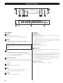
1
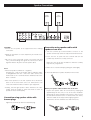
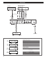
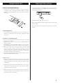
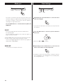
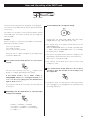
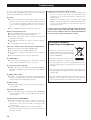
D00905700B
Digital Pre Main Amplifier
Owner’s Manual
IMPORTANT SAFETY INSTRUCTIONS
1) Read these instructions.
2) Keep these instructions.
CAUTION: TO REDUCE THE RISK OF ELECTRIC SHOCK,
DO NOT REMOVE COVER (OR BACK). NO USERSERVICEABLE PARTS INSIDE. REFER SERVICING TO
QUALIFIED SERVICE PERSONNEL.
3) Heed all warnings.
4) Follow all instructions.
5) Do not use this apparatus near water.
6) Clean only with dry cloth.
The lightning flash with arrowhead symbol, within an
equilateral triangle, is intended to alert the user to the
presence of uninsulated “dangerous voltage” within
the product’s enclosure that may be of sufficient
magnitude to constitute a risk of electric shock to
persons.
The exclamation point within an equilateral triangle is
intended to alert the user to the presence of important
operating and maintenance (servicing) instructions in
the literature accompanying the appliance.
7) Do not block any ventilation openings. Install in accordance
with the manufacturer’s instructions.
8) Do not install near any heat sources such as radiators, heat
registers, stoves, or other apparatus (including amplifiers) that
produce heat.
9) Do not defeat the safety purpose of the polarized or
grounding-type plug. A polarized plug has two blades with
one wider than the other. A grounding type plug has two
blades and a third grounding prong. The wide blade or the
third prong are provided for your safety. If the provided plug
does not fit into your outlet, consult an electrician for
replacement of the obsolete outlet.
10) Protect the power cord from being walked on or pinched
particularly at plugs, convenience receptacles, and the point
where they exit from the apparatus.
11) Only use attachments/accessories specified by the
manufacturer.
12) Use only with the cart, stand, tripod,
bracket, or table specified by the
manufacturer, or sold with the apparatus.
When a cart is used, use caution when
moving the cart/apparatus combination to
avoid injury from tip-over.
13) Unplug this apparatus during lightning storms or when
unused for long periods of time.
14) Refer all servicing to qualified service personnel. Servicing is
required when the apparatus has been damaged in any way,
such as power-supply cord or plug is damaged, liquid has
been spilled or objects have fallen into the apparatus, the
apparatus has been exposed to rain or moisture, does not
operate normally, or has been dropped.
< Do not expose this apparatus to drips or splashes.
< Do not place any objects filled with liquids, such as vases, on
the apparatus.
< Do not install this apparatus in a confined space such as a
book case or similar unit.
< The apparatus draws nominal non-operating power from the
AC outlet with its POWER switch in the off position.
< The apparatus should be located close enough to the AC
outlet so that you can easily grasp the power cord plug at any
time.
< An apparatus with Class ! construction shall be connected to
an AC outlet with a protective grounding connection.
2
WARNING: TO PREVENT FIRE OR SHOCK
HAZARD, DO NOT EXPOSE THIS APPLIANCE
TO RAIN OR MOISTURE.
Contents
Thank you for choosing Esoteric. Read this manual
carefully to get the best performance from this unit.
CAUTION
< DO NOT REMOVE THE EXTERNAL CASES OR CABINETS TO
EXPOSE THE ELECTRONICS. NO USER SERVICEABLE PARTS
ARE WITHIN!
Before Use . . . . . . . . . . . . . . . . . . . . . . . . . . . . . . . . . . . . . . . . 4
Speaker Connections . . . . . . . . . . . . . . . . . . . . . . . . . . . . . . . . 5
Connections . . . . . . . . . . . . . . . . . . . . . . . . . . . . . . . . . . . . . . . 6
< IF YOU ARE EXPERIENCING PROBLEMS WITH THIS PRODUCT,
CONTACT TEAC FOR A SERVICE REFERRAL. DO NOT USE THE
PRODUCT UNTIL IT HAS BEEN REPAIRED.
i.LINK (IEEE 1394) . . . . . . . . . . . . . . . . . . . . . . . . . . . . . . . . . . . 8
Remote Control Unit. . . . . . . . . . . . . . . . . . . . . . . . . . . . . . . . . 9
Restoring factory settings . . . . . . . . . . . . . . . . . . . . . . . . . . . . . 9
Front panel features . . . . . . . . . . . . . . . . . . . . . . . . . . . . . . . . 10
Understanding the remote control unit . . . . . . . . . . . . . . . . . . 11
For U.S.A.
This equipment has been tested and found to comply with the
limits for a Class B digital device, pursuant to Part 15 of the
FCC Rules. These limits are designed to provide reasonable
protection against harmful interference in a residential
installation. This equipment generates, uses, and can radiate
radio frequency energy and, if not installed and used in
accordance with the instructions, may cause harmful
interference to radio communications. However, there is no
guarantee that interference will not occur in a particular
installation. If this equipment does cause harmful interference
to radio or television reception, which can be determined by
turning the equipment off and on, the user is encouraged to
try to correct the interference by one or more of the following
measures:
• Reorient or relocate the equipment and/or the receiving
antenna.
• Increase the separation between the equipment and
receiver.
• Connect the equipment into an outlet on a circuit different
from that to which the receiver is connected.
• Consult the dealer or an experienced radio/TV technician
for help.
Basic Operation. . . . . . . . . . . . . . . . . . . . . . . . . . . . . . . . . . . . 12
Muting . . . . . . . . . . . . . . . . . . . . . . . . . . . . . . . . . . . . . . . . . . 13
Display dimming . . . . . . . . . . . . . . . . . . . . . . . . . . . . . . . . . . . 13
Word sync . . . . . . . . . . . . . . . . . . . . . . . . . . . . . . . . . . . . . . . 14
Basic Settings . . . . . . . . . . . . . . . . . . . . . . . . . . . . . . . . . . . . . 14
Gain Setting for Analog Audio Input . . . . . . . . . . . . . . . . . . . . 16
Name and skip setting of the INPUT knob . . . . . . . . . . . . . . . . 17
Troubleshooting . . . . . . . . . . . . . . . . . . . . . . . . . . . . . . . . . . . 18
Specifications . . . . . . . . . . . . . . . . . . . . . . . . . . . . . . . . . . . . . 19
CAUTION
Changes or modifications to this equipments not expressly
approved by TEAC CORPORATION for compliance will void the
user’s warranty.
CAUTION Regarding Placement
To maintain proper ventilation, be sure to leave a space
around the unit (from the largest outer dimensions including
projections) equal to, or greater than, shown below.
Left and Right Panels: 5 cm (2”)
Rear Panel: 10 cm (4”)
Top Panel: 20 cm (8”)
3
Before Use
What’s in the box
Please confirm that the following accessories are in the box
when you open it.
Remote control unit (RC-1056) x 1
Batteries (AA, R6, SUM-3) x 2
Felt sheet x 4
Power cord x 1
Owner’s manual x 1
Warranty card x 1
Read this before operation
< As the unit may become warm during operation, always leave
sufficient space around the unit for ventilation.
The ventilation holes should not be covered. Make sure there
is at least 20 cm (8”) of space above and at least 5 cm (2”) of
space on each side of the unit. Do NOT place anything on top
of the unit.
< The voltage supplied to the unit should match the voltage as
printed on the rear panel. If you are in any doubt regarding
this matter, consult an electrician.
< Choose the installation location of your unit carefully. Avoid
placing it in direct sunlight or close to a source of heat. Also
avoid locations subject to vibrations and excessive dust, heat,
cold or moisture.
< Do not place the unit on the amplifier/receiver.
< Do not open the cabinet as this might result in damage to the
circuitry or electrical shock. If a foreign object should get into
the unit, contact your dealer or service company.
< When removing the power plug from the wall outlet, always
pull directly on the plug, never yank the cord.
< Do not attempt to clean the unit with chemical solvents as
this might damage the finish. Use a clean, dry or slightly
damp cloth.
< To protect easily scratched furniture, you may stick the felt
supplied with the unit to the feet.
< Keep this manual in a safe place for future reference.
4
Maintenance
If the surface of the unit gets dirty, wipe with a soft cloth or
use diluted neutral cleaning liquid. Be sure to remove any
fluid completely. Do not use thinner, benzine (naphtha) or
alcohol as they may damage the surface of the unit.
Short Circuit and Output Protection
“OVER LEVEL” blinks on the display when the short circuit
protection (or the output protection) is activated. In this case,
turn the unit off and check the speaker cables. The metal
portions of the two separate wires should not touch.
If there is no shorted wire, turn down the volume using the
VOLUME knob.
Thermal Overload Protection
“HIGH TEMP” blinks on the display when the overload
protection is activated. In this case, turn the unit off and leave
it for a few hours to cool it down.
Also check the location of your unit. Place the unit in a cool
place, and always leave sufficient space around the unit for
ventilation.
“Super Audio CD” is a registered trademark.
“DSD” is a registered trademark.
The i.LINK logo is a trademark of Sony Corporation, registered in
the U.S. and other countries.
Speaker Connections
Right
Speaker
CAUTION:
< Switch off the power to all equipment before making
connections.
< Read the instructions of each component you intend to use
with this unit.
< Be sure to insert each plug securely. To prevent hum and
noise, avoid bundling the signal interconnection cables
together with the AC power cord or speaker cables.
Left
Speaker
Connection using speaker cables with
spades or bare wire
1. Turn the terminal cap counterclockwise to loosen it. The
speaker terminal caps cannot be fully removed from the base.
2. Insert the wire or spade into the terminal and turn the
terminal cap clockwise to securely connect it:
Make sure none of the wire insulation is under the terminal,
only the bare, stripped wire.
3. Make sure it is fastened firmly by pulling the cable lightly.
Note:
< The black speaker terminals are – (negative).
Generally, the + side of the speaker cable is marked to make
it distinguishable from the – side of the cable. Connect this
marked side to the + terminal and the unmarked side to the
black – terminal.
< The inside diameter of spades should be 8 mm or more.
< The metal portions of the two separate wires should not
touch or an electrical short can occur. Shorted wires can
create a fire hazard or induce a failure in your equipment.
< Ideally, left and right speaker cables should be the same
length. And the length of cables should be as short as
possible for better sound quality.
Connection using speaker cables with
banana plugs
When your speaker cable has bare wire at the end
Prepare the speaker cables for connection by stripping off
approximately 10 mm (1/2”) or less of the outer insulation.
(Removing too much insulation may lead to a short circuit if
the bared wired should come in contact with each other.)
Twist the strands of the stripped wires tightly together.
The thickness of wires should be less than 4 mm (1/8”).
Tighten the terminal cap and insert a banana plug.
5
Connections
Master clock generator
(G-0s, AZ-1, etc.)
Turntable
DIGITAL OUT
BNC coaxial cable
i.LINK cable
A
optical digital cable
B
RCA coaxial cable
Connect one of
these cables.
WORD SYNC
IN
D
C
B
E
Supplied power cord
RCA cable
AUDIO OUT
Wall socket
Tuner, Cassette tape deck, etc.
When you are using two or three AZ-1 units for multi-channel listening, connect them as shown here.
SZ-1
UZ-1
AZ-1
(L/R)
6
WORD SYNC
IN
i.LINK(AUDIO)
(IEEE 1394)
WORD SYNC
OUT
i.LINK(AUDIO)
i.LINK(AUDIO)
AZ-1
(C/LFE)
i.LINK(AUDIO)
i.LINK(AUDIO)
AZ-1
(LS/RS)
i.LINK(AUDIO)
Setting of the SZ-1/UZ-1
i.LINK button
“PCM”
WORD button
“ON”
Analog Out setting “Multi ch”
Digital Out setting “ON”
CD Direct setting
“Normal”
Speaker setting
necessary
Setting of the AZ-1
INPUT
“i.LINK”
WORD button
One of the AZ-1 that receives channel
L/R: “W_OUT”
The others: “OFF”
W_OUT setting
“176.4” or “88.2”
CH setting
respective channels
i_RC setting
“ON”
CAUTION:
< Switch off the power to all equipment before making
connections.
< Read the instructions of each component you intend to use
with this unit.
< Be sure to insert each plug securely. To prevent hum and
noise, avoid bundling the signal interconnection cables
together with the AC power cord or speaker cables.
A Digital audio input terminals [DIGITAL IN]
Connect any one of these terminals to the digital output
terminal of a digital device (SZ-1, UZ-1, etc.) using a
commercially available cable.
COAXIAL (RCA): Use RCA (pin) digital audio cable
OPTICAL: Use optical digital audio cable (TOS)
i.LINK (AUDIO): Use S400 compatible IEEE1394 6pin cable
< The i.LINK (AUDIO) terminal is an interface that transmits
data both ways between the AZ-1 and an external device.
You don’t need to be concerned with distinguishing
between inputs and outputs.
LINE3/PHONO terminal
In addition to a cassette tape deck or tuner, you can also
connect a turntable to this terminal.
Connect the ground lead of the turntable to the SIGNAL
GND terminal of the AZ-1. (But if low frequency noises are
heard, it might be better not to connect the ground lead.)
The cartridge of the turntable should be Moving Magnet or
similar.
LINE3/PHONO switch
Select PHONO when a turntable is connected to the
LINE3/PHONO terminal. Select LINE3 when a cassette tape
deck, tuner, etc. is connected to the LINE3/PHONO terminal.
C SIGNAL GND connection
Use a commercially available PVC-covered cord to connect
the signal ground terminal on the unit to the player’s signal
ground.
< Note that this is NOT an electrical safety ground (earth).
< When a turntable is connected, make sure to connect the
ground lead of the turntable.
D WORD SYNC output terminal
< The optical terminal is covered by a shutter. Make sure that
the cable is firmly inserted, but do not force the cable when
connecting it or removing it, in order not to cause damage
to the unit.
< The COAXIAL (RCA) and OPTICAL terminals cannot transmit
the digital audio from Super Audio CDs.
< If Esoteric SZ-1 or UZ-1 is connected to the AZ-1 using an
i.LINK cable, the following setup will provide you with the
best quality sound:
i.LINK button: PCM
Digital Output setting: ON
This sends out a sync signal (word).
Connect this to the WORD IN terminal of a digital device
such as the SZ-1, UZ-1, etc.
For connection, use a commercially available BNC coaxial
digital cable (75Ω impedance).
E Power cord receptacle
After all other connections have been made, insert the
supplied AC power cord into this receptacle, then connect
the other end of the power cord into the wall socket. Ensure
that your AC voltage corresponds to the voltage marked on
the rear panel of the unit. Consult a qualified electrician if
you are in doubt.
B Analog audio input terminals [LINE IN]
Used for the input of analog 2-channel audio signals from a
cassette tape deck, tuner, etc.
Connect the component with commercially-available RCA
cables.
< In order to avoid the risk of electric shock, fire, and so on,
only use the supplied power cord.
< If you are not going to use the unit for some time,
disconnect the power cord from the wall socket.
Make sure to connect :
white plug q white jack (L: left channel)
red plug q red jack (R: right channel)
7
i.LINK (IEEE 1394)
i.LINK is also known as IEEE 1394, an international specification.
This unit is ready to accept i.LINK (AUDIO).
By connecting an i.LINK (AUDIO)-capable device to the IEEE
1394, or i.LINK (AUDIO) terminal on this unit using an i.LINK
cable, you can transmit Super Audio CD multi-channel signals
that could not be transmitted except in analog format in the
past. Now a Super Audio CD digital signal can be transmitted in
its original digital format in addition to transmitting 2-ch linear
PCM data and multi-channel compressed audio signals.
If you have multiple i.LINK-capable devices, you can connect
them through other devices to transmit data between them, so
you don’t need to be concerned with the order of connection.
< Among the i.LINK formats there are “MPEG-2 TS” for BS
digital source and “DV” for digital video for DVD recorders,
as well as the “i.LINK (AUDIO)” (A&M Protocol). Never
connect devices that are not ready for i.LINK (AUDIO) to this
unit. If you do, this unit and others may get erroneous data
or be damaged.
Copyright protection system DTCP
< There is a possibililty some i.LINK-capable devices will not
respond to this unit's command.
To play back audio sounds recorded on Super Audio CD or DVD
discs using i.LINK, both the player and the D/A converter need to
be ready for the copyright protection system DTCP (Digital
Transmission Content Protection).
This unit is equipped with DTCP.
Data transfer rate
There are three transfer rates using i.Link: 100 Mbps (S100), 200
Mbps (S200), and 400 Mbps (S400). This unit is capable of
transferring data at the maximum 400Mbps.
For connection to an i.LINK-capable device, use a commercially
available S400-compliant 6-pin i.LINK cable.
When connecting multiple i.LINK-capable devices, avoid
connecting a device having slow transfer rate between devices
having high transfer rate since this reduces the transfer rate of
your whole system. Connect devices having high transfer rate
towards the source as far up-stream as possible.
< Avoid plugging or unplugging the i.LINK cables while the
player is in use. Preferably, make all connections when the
power is off.
< Among the i.LINK-capable devices there are some that, if not
turned on, are not capable of relaying data.
How to connect multiple i.LINK-capable
devices
Daisy-chain connection
You can daisy-chain up to 17 devices including this unit.
i.LINK cable
i.LINK-capable
device
This unit supports i.LINK flow rate control. Flow rate control
means that audio data transferred via i.LINK is first stored in
RAM of this unit after which the high-precision clock in the unit
is used to retrieve the data from RAM to avoid the transfer jitter
normally associated with i.LINK transfer. This unit transfers
commands to the playback device to change the data transfer
rate and control the playback device when data accumulated in
RAM exceeds or goes below a certain amount due to differences
in clock frequencies in the playback device and this unit. Flow
rate control functions in transfers between this unit and another
unit.
i.LINK-capable
device
i.LINK-capable
device
Connection in tree structure
If you are using a device having three or more i.LINK connectors,
you may want to get the connection branched out. This way of
connection allows you to connect up to 17 devices including this
unit.
i.LINK-capable
device
NOTES
Flow rate control
i.LINK-capable
device
i.LINK-capable
device
i.LINK-capable
device
i.LINK-capable
device
i.LINK-capable
device
Your system will not work if data is fed back to the original
output device. Be careful not to create a loop.
i.LINK-capable
device
i.LINK-capable
device
i.LINK-capable
device
i.LINK-capable
device
i.LINK-capable
device
i.LINK-capable
device
The i.LINK interface of this unit is designed in accordance with
the following specifications:
1) IEEE Std 1394a-2000, Standard for a High Performance
Serial Bus
2) Audio and Music Data Transmission Protocol 2.0
This unit is compliant with IEC 60958 bitstream, DVD-Audio,
Super Audio CD in the AM824 sequence adaptation layers of
this protocol.
8
Remote Control Unit
How to insert the batteries
Remove the cover of the remote control unit with a
screwdriver. After checking the polarity (+/_) of two AA
batteries, insert the batteries, replace the cover and replace
the screws.
Restoring factory settings
If you have made a lot of changes to the setup, and want to
restart from a known set of options, restore the unit to the
factory settings as follows:
1. Unplug the power cord from the outlet.
2. While holding down the SETUP button, plug the power cord
into the outlet.
All memories are erased, and the unit returns to the factory
settings.
Battery Replacement
If the distance you can operate your remote decreases, the
batteries are exhausted. In this case replace the batteries with
new ones.
Precautions concerning batteries
< Be sure to insert the batteries with correct positive “+” and
negative “_” polarities.
< Use batteries of the same type. Never use different types of
batteries together.
< Rechargeable or non-rechargeable batteries can be used but
not mixed together. Refer to the precautions on their labels.
< When the remote control unit is not to be used for a long
time (more than a month), remove the batteries from the
remote control unit to prevent them from leaking. If they
leak, wipe away the liquid inside the battery compartment
and replace the batteries with new ones.
< Do not heat or disassemble batteries and never dispose of old
batteries by throwing them in a fire.
Notes on use
< Point the remote control unit at the main unit’s remote sensor
within seven meters (23 feet) of the main unit. There should
not be any obstacles between the main unit and the remote
control unit.
< Do not allow direct sun or other light to shine on the remote
sensor part of the main unit. This may cause the remote
control unit to work incorrectly.
< Note that other units with remote controls may operate
incorrectly because of infrared light “overspill” when you
operate this remote control unit.
9
Front panel features
Display
ディスプレー
A
a
B C
D
b
E F
c
d
Front Panel
Display
A INPUT
a i.LINK indicator
Turn this knob to select an input.
In the setup mode, use this knob to change settings.
B STANDBY
Use this button to turn the unit on and to standby.
The indicator is red in the standby mode. It turns blue when
the unit is turned on.
The equipment draws nominal non-operating power from
the AC outlet with its STANDBY switch in the standby
position.
C SETUP
Press this button to enter or exit the basic setup mode.
Press and hold this button for more than 2 seconds to enter
or exit “Gain Setting for Analog Audio Input” or “Name and
skip setting of the INPUT knob” mode.
D Remote control sensor
Receives signals from the remote control unit. Point the
remote control unit at this sensor when operating the remote
control unit.
G
Lights when the INPUT knob is set to “i.LINK” or when i_RC
setting is set to ON.
This indicator blinks when the unit cannot perceive the digital
signal. In that case, connect a digital device to the i.LINK
(AUDIO) terminal and switch it on.
b SETUP indicator
Lights while in the setup mode.
c Message area
Alphanumeric display to show sources, sampling frequencies,
status messages, etc.
Normally, “current input” is shown on the left of the display.
When detecting a device that is connected with i.LINK cable,
the display shows its model name (such as SZ-1).
The right of the display shows “the sampling frequency of an
incoming digital signal” when a CD is played back or “DSD”
when a Super Audio CD is played back.
d Channel indicators
Channels selected during “CH” setup light.
E MUTING
Use this button to mute the sound.
F WORD
Use this to turn on or off the word sync function.
The indicator lights when the word sync is on.
G VOLUME
Turn this knob to adjust the volume.
10
Understanding the remote control unit
Note:
To simplify explanations, instructions in this manual refer to
the names of the buttons and controls on the front panel
only. Associated controls on the remote control will also
operate similarly.
A
A ON/STANDBY
Use the ON button to turn the unit on.
Use the STANDBY button to turn it standby.
G
B VOLUME
Use these buttons to adjust the volume.
C DIMMER
Use this button to change the brightness of the front panel
display.
B
F
D SETUP
Use this button to enter or exit the setup mode.
C
D
E
E MUTING
Use this button to mute the sound.
F INPUT
Use these buttons to select an input.
G Buttons for the basic operation of Esoteric SZ-1 or UZ-1
You can use these buttons to operate Esoteric SZ-1 or UZ-1.
Point the remote control unit at the remote sensor of the SZ-1
or UZ-1.
11
Basic Operation
3 2
1 First of all, turn on the power of the connected
components.
4
4 Play the source, and gradually turn up the volume to
the required level by turning the VOLUME knob.
2 Press the STANDBY button to turn the unit on.
The indicator is red in the standby mode. It turns blue when
the unit is turned on.
standby indicator
To turn the unit off (standby)
It may take several seconds for the unit to start outputting
sounds. Wait until “WAIT ...” disappears from the display.
To prevent sudden noise from the speakers, make sure to turn
the unit off in the following way.
1. Stop the playback of the connected component.
3 Select an input by turning the INPUT knob.
The current input appears on the left of the display.
Repeatedly turn the knob until the desired input appears on
the display.
COAX1, COAX2, OPT1, OPT2, LINE1, LINE2,
LINE3 or PHONO*, i.LINK
*: PHONO appears only when the LINE/PHONO switch is set to
PHONO.
< When you select a digital terminal, “the sampling frequency
of an incoming digital signal” or “DSD” appears on the right
of the display.
< i.LINK indicator blinks when the unit cannot recognize the
digital signal. In that case, connect a digital device to the
i.LINK(AUDIO) terminal and switch it on.
12
2. Turn the AZ-1 standby using the STANDBY button.
3. Turn the connected components off.
Muting
To mute the sound temporarily, press the MUTING button.
Press the MUTING button again to restore the sound.
< While muting is engaged, “MUTING” and the name of the
selected terminal alternately blink on the display.
Display dimming
The display on the main unit can be dimmed to suit the
environment in which you listen to music. There are three
levels and an “off” setting.
Use the DIMMER button to cycle between these
settings.
< Note that the OFF setting is not memorized when the power
is turned off. When the unit is switched off with the display
off, and then turned on again, the display is reset to the
minimum brightness.
< In OFF mode, when you press a button such as VOLUME, the
illuminations turn temporarily on.
13
Word sync
Basic Settings
INPUT
This feature is used when you want to get your whole system
locked to a single sync signal (clock) by connecting this unit to
the Esoteric SZ-1/UZ-1 or other devices that are capable of
inputting a sync signal (word clock).
Use the WORD button to switch between W_OUT and
WORD OFF.
SETUP
1 Repeatedly press the SETUP button to select the menu
item to be changed.
< If you leave the unit idle for 10 seconds, the setup mode will
be cancelled.
W_OUT
The unit internally generates and sends out Word Clock.
The indicator lights.
You can change the frequency of the word sync signal. See
pages 14 and 15 for details.
2 Turn the INPUT knob to select the options within the
menu item.
< Make WORD SYNC connections before powering on the unit.
< It takes several seconds to detect and lock to a clock.
If the received digital signal doesn’t match the sync signal, the
display shows “WRD ERROR!”.
< Repeat steps 1 and 2 as required.
WORD OFF
3 Repeatedly press the SETUP button (or leave the unit
The unit does not output a word clock.
idle for 10 seconds) to exit the setup mode.
< Settings are stored even when power is turned off and the
unit is unplugged. If left unplugged for an extended period,
the settings may be lost.
14
W_OUT (Word sync output frequency)
Select the frequency of the word sync signal. The factory
setting is “44.1”.
100 a
q 44.1 a
q 88.2 a
q 176(176.4) a
q 48 a
q 96 a
q 192
< The word sync signal is output only when the WORD button
is set to “W`_OUT” (see page 14).
CH (Channel)
When the i.LINK (AUDIO) terminal is connected to a digital
device, select the channels for this unit.
The factory setting is L/R.
L/R: front left and right channels
C/LFE: center channel and LFE (subwoofer)
LS/RS: surround left and right channels
< The icons of the selected channels light on the display.
Note
When two AZ-1’s are connected using i.LINK cables and one
AZ-1 is connected to the front left speaker and the other AZ-1
is connected to the front right speaker as shown below, one
AZ-1 can be used as an amplifier dedicated to the left channel
and the other as an amplifier dedicated to the right channel.
Speaker
Speaker
SZ-1/UZ-1
i.LINK(AUDIO)
(IEEE 1394)
AZ-1 (L/R)
i.LINK(AUDIO)
i.LINK(AUDIO)
AZ-1 (L/R)
i.LINK(AUDIO)
i_RC (i.LINK remote control function)
When multiple AZ-1 units are directly connected using i.LINK
cables and you use this function, the volume, muting and
dimmer of all AZ-1’s in the chain can be controlled using only
one AZ-1.
The MASTR and SLAVE settings of the i.LINK remote control
function allow you to set one AZ-1 as master and the other as
slave, so that the volume, muting and dimmer of the two AZ1’s can be controlled in unison using one of the pair units.
Since this function is available as long as AZ-1’s are connected
using i.LINK cables, you can use a different input type other
than i.LINK.
ON
The volume, muting and dimmer of all AZ-1’s in the chain can
be controlled using the L/R channel AZ-1.
MASTR
SLAVE
When you set one AZ-1 as master and all other AZ-1’s as
slaves, the volume, muting and dimmer of all AZ-1’s in the
chain can be controlled using only the master unit.
This master-slave control has nothing to do with the channel
setting.
OFF (default setting)
Select this setting position when the i.LINK remote control is
not used. The volume, muting and dimmer of all AZ-1’s in the
chain cannot be controlled as a whole.
The i.LINK circuit is powered only when the input is set to
i.LINK.
(Normal display)
Select this to exit the setup mode.
15
Gain Setting for Analog Audio Input
INPUT
SETUP
You can adjust the relative volume between the LINE IN
terminals. Once the relative volume is set, each component
connected to the AZ-1 will have the approximate same volume
level.
4 Press and hold the SETUP button for more than 2
1 Select an input to be changed (LINE1, LINE2 or
< Settings are stored even when power is turned off and the
unit is unplugged. If left unplugged for an extended period,
the settings may be lost.
LINE3/PHONO) by turning the INPUT knob.
Start with the component that has the lowest volume level.
seconds (or leave the unit idle for 10 seconds) to exit
the Gain setup mode.
< If you lightly press the SETUP button, the unit enters name
and skip setting mode. See page 17 for details.
2 Press and hold the SETUP button for more than 2
seconds.
The unit enters setup mode, and “GainL*>***” appears on
the display. (*** changes depending on your setting.)
If you leave the unit idle for 10 seconds, the setup mode will
be cancelled.
3 Turn the INPUT knob to change the Gain setting.
Adjustable range: 0, +3, +6, +9, +12, +15, +18, +21, +24
16
Name and skip setting of the INPUT knob
INPUT
SETUP
The names of the inputs shown on the display can be changed.
You can also set the INPUT knob to skip the input terminals that
are not in use.
3 Turn the INPUT knob to change the setting.
For example, if a CD player is connected to the COAX1 terminal
and a DVD player to the OPT1 terminal, you can change the
name of COAX1
Example:
When a CD player is connected to the COAX1 terminal and a
DVD player to the OPT1 terminal
Select “CD” for COAX1
Select “DVD” for OPT1
Select “*skip” for other terminals.
Then only “CD” or “DVD” will appear on the display when
you turn the INPUT knob.
1 Press and hold the SETUP button for more than 2
seconds.
Default name, CD, SACD, DVD, TUNER, MD, CD-R, TAPE,
PHONO, MP3, TV, SAT, CATV, DVD-R, VCR, *skip
< The default name of the LINE3 terminal depends on the
LINE3/PHONO switch.
When the LINE/PHONO switch is set to LINE, the default name
is “LINE3”. When the LINE/PHONO switch is set to PHONO,
the default name is “PHONO”.
< The name of the i.LINK terminal cannot be changed, as the
display always shows model name of the connected device.
Only “*skip” is selectable for i.LINK.
< Skip function will not work at all if you set all the input
terminals to “*skip”.
4 Press and hold the SETUP button for more than 2
The unit enters setup mode, and “L-1>***” appears on the
display. (*** changes depending on your setting.)
seconds (or leave the unit idle for 10 seconds) to exit
the setup mode.
If the INPUT knob is set to LINE1, LINE2 or
LINE3/PHONO, “GainL*>***” will appear instead of “L1> *** ”. In this case, lightly press the SETUP button
again to show “L-1>***”.
If you leave the unit idle for 10 seconds, the setup mode will
be cancelled.
< Settings are stored even when power is turned off and the
unit is unplugged. If left unplugged for an extended period,
the settings may be lost.
2 Repeatedly press the SETUP button to select the input
terminal to be changed.
L-1(LINE1) q L-2(LINE2) q L-3(LINE3)
q i-L(i.LINK) q C-1(COAX1) q C-2(COAX2)
q O-1(OPT1) q O-2(OPT2) q (normal display)
q L-1(LINE1) q ...
17
Troubleshooting
In case you experience any problem with this unit, please take
the time to look through this chart and see if you can solve the
problem yourself before you call your dealer.
No power
e Check the connection to the AC power supply. Check and
make sure the AC source is not a switched outlet and that,
if it is, the switch is turned on. Make sure there is power to
the AC outlet by plugging another item such as a lamp or
fan.
e Press the POWER switch of the main unit to turn it on.
Remote control doesn’t work.
e Press the POWER switch of the main unit to turn it on.
e If the batteries are dead, change the batteries.
e Use remote control unit within the range (5m /15ft) and
point at the front panel.
e Clear obstacles between the remote control unit and the
main unit.
e If a strong light is near the unit, turn it off.
There is no sound or only a very low-level sound is heard.
e Adjust the volume by turning the VOLUME knob.
e Select the proper source using the INPUT knob.
e Check that the speakers and components are connected
securely.
e Check the operation of the connected component.
No i.LINK output.
e Check the channel setting. One AZ-1 unit must be set to L/R
channel when multiple AZ-1 units are connected.
No sound from a Super Audio CD.
e Digital audio from a Super Audio CD cannot go through the
OPTICAL or COAXIAL terminals. Use the i.LINK (AUDIO)
terminal.
No digital audio output.
e The AZ-1 isn’t equipped with Dolby Digital/DTS/MPEG
decoders. The digital output setting of the connected player
must be PCM. Or use analog audio terminals.
Unstable sound.
e Speaker polarity (+/_) is reversed. Check all speakers for
correct polarity.
The i.LINK indicator blinks.
e Turn on the digital device connected to the i.LINK(AUDIO)
terminal. When you don’t use the i.LINK terminal, turn the
i_RC setting off.
The display shows “WRD ERROR!”
e The connected unit may not be in word sync mode while
the AZ-1 is in word sync mode. Check the word sync
terminal for correct connection and the settings on the
connected unit.
e The received digital signal doesn’t much the sync signal.
The proper word sync frequencies for Super Audio CDs are
44.1, 88.2 or 176.4.
18
Buzzing noise produced at regular intervals.
e The connected unit may not be in word sync mode while
the AZ-1 is in word sync mode. Check the word sync
terminal for correct connection and the settings on the
connected unit.
Normally, if this problem occurs, the display reads “WRD
ERROR!”, but this message does not appear when deviation
in sync is too small and out of the word error detection
threshold of the AZ-1.
If normal operation cannot be obtained, unplug the power
cord from the outlet and plug it again. This resets the
internal micro-computer which can be disturbed during
electrical storms, power interruptions, et cetera.
For European customers
Disposal of your old appliance
1. When this crossed-out wheeled bin
symbol is attached to a product it means
the product is covered by the European
Directive 2002/96/EC.
2. All electrical and electronic products
should be disposed of separately from
the municipal waste stream via designated collection
facilities appointed by the government or the local
authorities.
3. The correct disposal of your old appliance will help prevent
potential negative consequences for the environment and
human health.
4. For more detailed information about disposal of your old
appliance, please contact your city office, waste disposal
service or the shop where you purchased the product.
Specifications
General
Power supply
Europe model. . . . . . . . . . . . . . . . . . . . . . . . . . . . . . . . . . . . . . . . . . . . . AC 230 V, 50 Hz
U.S.A./Canada model . . . . . . . . . . . . . . . . . . . . . . . . . . . . . . . . . . . . . . . AC 120 V, 60 Hz
Korea model . . . . . . . . . . . . . . . . . . . . . . . . . . . . . . . . . . . . . . . . . . . . . AC 220 V, 60 Hz
Power consumption . . . . . . . . . . . . . . . . . . . . . . . . . . . . . . . . . . . . . . . . . . . . . . . . . . . 45 W
Weight . . . . . . . . . . . . . . . . . . . . . . . . . . . . . . . . . . . . . . . . . . . . . . . . . . . 9.2 kg (20 1/4 lbs)
External dimensions (W x H x D) . . . . . . . . 400 x 77 x 372 mm (15 3/4” x 3 1/16” x 14 5/8”)
Operating temperature . . . . . . . . . . . . . . . . . . . . . . . . . . . . . . . . . . . . . . . . . . . +5˚C - +35˚C
Operating humidity . . . . . . . . . . . . . . . . . . . . . . . . . . . . . . . . 5% to 85% (no condensation)
Storage temperature . . . . . . . . . . . . . . . . . . . . . . . . . . . . . . . . . . . . . . . . . . . . –20˚C - +55˚C
Digital Input Terminals
Input format . . . . . . . . . . . . . . . . . . . . . . . . . . DSD, linear PCM (44.1kHz-192kHz, 16-24bit)
i.LINK (AUDIO) terminal (6pin) x2
RCA x2, Input level: more than 0.2Vp-p/75Ω
OPTICAL x2, Input level: –24.0 to –14.5dBm peak
Amplifier Section
Output Power . . . . . . . . . . . . . . . . . . . . . . . . . . . . . . . . . . . . .45 W + 45 W (1 kHz, 8 ohms)
75 W + 75 W (1 kHz, 4 ohms)
Minimum impedance. . . . . . . . . . . . . . . . . . . . . . . . . . . . . . . . . . . . . . . . . . . . . . . . . 4 ohms
Total Harmonic Distortion . . . . . . . . . . . . . . . . . . . . . . . . . 0.04 % (at 47 W, 1 kHz, 8 ohms)
Frequency Response (COAXIAL, OPTICAL, i.LINK) . . . 5 Hz to 95 kHz, –3 dB (at 1 W, 8 ohms)
Signal-to-Noise Ratio (COAXIAL, OPTICAL, i.LINK) . . . . . . . . . . . . . more than 115 dB (JEITA)
Input Sensitivity (maximum output at maximum volume) . . . . . . . . . . . . . . LINE: 150 mVrms
LINE3 PHONO (MM): 3.2 mVrms
Input impedance . . . . . . . . . . . . . . . . . . . . . . . . . . . . . . LINE: 100 kΩ, PHONO (MM): 39 kΩ
RIAA deviation. . . . . . . . . . . . . . . . . . . . . . . . . . . . . . PHONO (MM): ±0.5 dB (20 Hz-15 kHz)
Word Clock
Jack . . . . . . . . . . . . . . . . . . . . . . . . . . . . . . . . . . . . . . . . . . . . . . . . . . . . . . . . . . . . . . . . BNC
Output level . . . . . . . . . . . . . . . . . . . . . . . . . . . . . . . . . . . . . . . . . . . . . . . . . . . TTL level/75Ω
Word Clock Output Frequency . . . . . . . . . . . . . . . 44.1, 88.2, 176.4, 48, 96, 192, 100 (kHz)
Accessories
Remote control unit (RC-1056) x 1
Batteries (AA, R6, SUM-3) x 2
Felt sheet x 4
Power cord x 1
Owner’s manual x 1
Warranty card x 1
• Design and specifications are subject to change without notice.
• Weight and dimensions are approximate.
• Illustrations may differ slightly from production models.
19
TEAC ESOTERIC COMPANY
3-7-3, Nakacho, Musashino-shi, Tokyo 180-8550, Japan Phone: (0422) 52-5132 e-mail: [email protected]
TEAC AMERICA, INC.
7733 Telegraph Road, Montebello, California 90640 Phone: (323) 726-0303
TEAC CANADA LTD.
5939 Wallace Street, Mississauga, Ontario L4Z 1Z8, Canada Phone: (905) 890-8008
TEAC MEXICO, S.A. De C.V
Campesinos N°184, Colonia Granjas Esmeralda, Delegacion Iztapalapa, CP 09810, México DF Phone: (525) 581-5500
TEAC UK LIMITED
Unit 19 & 20, The Courtyards, Hatters Lane, Watford, Hertfordshire, WD18 8TE, U.K. Phone: (0845) 130-2511
TEAC EUROPE GmbH
Bahnstrasse 12, 65205 Wiesbaden-Erbenheim, Germany Phone: 0611-71580
This appliance has a serial number located on the rear panel. Please record
the model number and serial number and retain them for your records.
Model number
Serial number
0706 . MA-1033B