1
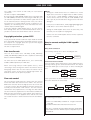
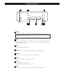
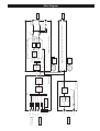
D-03
D/A Converter
Owner’s Manual
WARNING: TO PREVENT FIRE OR SHOCK
HAZARD, DO NOT EXPOSE THIS APPLIANCE
TO RAIN OR MOISTURE.
CAUTION: TO REDUCE THE RISK OF ELECTRIC SHOCK,
DO NOT REMOVE COVER (OR BACK). NO USERSERVICEABLE PARTS INSIDE. REFER SERVICING TO
QUALIFIED SERVICE PERSONNEL.
The lightning flash with arrowhead symbol, within an
equilateral triangle, is intended to alert the user to the
presence of uninsulated “dangerous voltage” within the
product’s enclosure that may be of sufficient magnitude
to constitute a risk of electric shock to persons.
The exclamation point within an equilateral triangle is
intended to alert the user to the presence of important
operating and maintenance (servicing) instructions in the
literature accompanying the appliance.
IMPORTANT SAFETY INSTRUCTIONS
1)
2)
3)
4)
5)
6)
7)
Read these instructions.
Keep these instructions.
Heed all warnings.
Follow all instructions.
Do not use this apparatus near water.
Clean only with dry cloth.
Do not block any ventilation openings. Install in accordance with
the manufacturer’s instructions.
8) Do not install near any heat sources such as radiators, heat
registers, stoves, or other apparatus (including amplifiers) that
produce heat.
9) Do not defeat the safety purpose of the polarized or groundingtype plug. A polarized plug has two blades with one wider than
the other. A grounding type plug has two blades and a third
grounding prong. The wide blade or the third prong are provided
for your safety. If the provided plug does not fit into your outlet,
consult an electrician for replacement of the obsolete outlet.
10) Protect the power cord from being walked on or pinched
particularly at plugs, convenience receptacles, and the point
where they exit from the apparatus.
11) Only use attachments/accessories specified by the manufacturer.
12) Use only with the cart, stand, tripod,
bracket, or table specified by the
manufacturer, or sold with the apparatus.
When a cart is used, use caution when
moving the cart/apparatus combination to
avoid injury from tip-over.
13) Unplug this apparatus during lightning storms or when unused
for long periods of time.
14) Refer all servicing to qualified service personnel. Servicing is
required when the apparatus has been damaged in any way,
such as power-supply cord or plug is damaged, liquid has been
spilled or objects have fallen into the apparatus, the apparatus
has been exposed to rain or moisture, does not operate normally,
or has been dropped.
< Do not expose this apparatus to drips or splashes.
< Do not place any objects filled with liquids, such as vases, on the
apparatus.
< Do not install this apparatus in a confined space such as a book
case or similar unit.
< The apparatus draws nominal non-operating power from the AC
outlet with its POWER switch in the off position.
< The apparatus should be located close enough to the AC outlet
so that you can easily grasp the power cord plug at any time.
< An apparatus with Class ! construction shall be connected to an
AC outlet with a protective grounding connection.
2
CAUTION
< DO NOT REMOVE THE EXTERNAL CASES OR CABINETS TO
EXPOSE THE ELECTRONICS. NO USER SERVICEABLE PARTS
ARE WITHIN!
< IF YOU ARE EXPERIENCING PROBLEMS WITH THIS PRODUCT,
CONTACT TEAC FOR A SERVICE REFERRAL. DO NOT USE THE
PRODUCT UNTIL IT HAS BEEN REPAIRED.
For U.S.A.
This equipment has been tested and found to comply with the
limits for a Class B digital device, pursuant to Part 15 of the
FCC Rules. These limits are designed to provide reasonable
protection against harmful interference in a residential
installation. This equipment generates, uses, and can radiate
radio frequency energy and, if not installed and used in
accordance with the instructions, may cause harmful
interference to radio communications. However, there is no
guarantee that interference will not occur in a particular
installation. If this equipment does cause harmful interference
to radio or television reception, which can be determined by
turning the equipment off and on, the user is encouraged to
try to correct the interference by one or more of the following
measures:
• Reorient or relocate the equipment and/or the receiving
antenna.
• Increase the separation between the equipment and
receiver.
• Connect the equipment into an outlet on a circuit different
from that to which the receiver is connected.
• Consult the dealer or an experienced radio/TV technician
for help.
CAUTION
Changes or modifications to this equipments not expressly
approved by TEAC CORPORATION for compliance will void the
user’s warranty.
CAUTION
Ensure this product is not exposed to dripping or splashing
and that no object filled with liquids, such as vases, is placed
on the product.
Do not install this equipment in a confined space such as a
book case or similar unit. Allow adequate air circulation
around this product.
For European customers
Contents
Disposal of your old appliance
1. When this crossed-out wheeled bin
symbol is attached to a product it means
the product is covered by the European
Directive 2002/96/EC.
Thank you for choosing Esoteric. Read this manual
carefully to get the best performance from this unit.
2. All electrical and electronic products should be disposed of
separately from the municipal waste stream via designated
collection facilities appointed by the government or the
local authorities.
Features . . . . . . . . . . . . . . . . . . . . . . . . . . . . . . . . . . . . . . . . . . 4
3. The correct disposal of your old appliance will help prevent
potential negative consequences for the environment and
human health.
Before Use . . . . . . . . . . . . . . . . . . . . . . . . . . . . . . . . . . . . . . . . 5
Connections . . . . . . . . . . . . . . . . . . . . . . . . . . . . . . . . . . . . . . . 6
Connection examples (connecting three D-03) . . . . . . . . . . . . . 8
i.LINK (IEEE 1394) . . . . . . . . . . . . . . . . . . . . . . . . . . . . . . . . . . . 9
Front panel features . . . . . . . . . . . . . . . . . . . . . . . . . . . . . . . . 10
Basic Operation. . . . . . . . . . . . . . . . . . . . . . . . . . . . . . . . . . . . 11
4. For more detailed information about disposal of your old
appliance, please contact your city office, waste disposal
service or the shop where you purchased the product.
Display dimming . . . . . . . . . . . . . . . . . . . . . . . . . . . . . . . . . . . 11
Word sync . . . . . . . . . . . . . . . . . . . . . . . . . . . . . . . . . . . . . . . 12
Digital filter. . . . . . . . . . . . . . . . . . . . . . . . . . . . . . . . . . . . . . . 12
Changing settings. . . . . . . . . . . . . . . . . . . . . . . . . . . . . . . . . . 13
Major settings. . . . . . . . . . . . . . . . . . . . . . . . . . . . . . . . . . . . . 14
Messages . . . . . . . . . . . . . . . . . . . . . . . . . . . . . . . . . . . . . . . . 14
Troubleshooting . . . . . . . . . . . . . . . . . . . . . . . . . . . . . . . . . . . 15
Specifications . . . . . . . . . . . . . . . . . . . . . . . . . . . . . . . . . . . . . 15
Block Diagram . . . . . . . . . . . . . . . . . . . . . . . . . . . . . . . . . . . . 16
3
Features
This independent D/A converter explores new musical
frontiers in a manner only possible to Esoteric, the
acknowledged leader in Super Audio CD/CD playback.
The D-03 delivers high-quality reproduction of DSD stream
signals, 192 kHz/24-bit high-sampling PCM signals and other
data-rich formats without data loss.
It has been specifically developed to reproduce the ambience
and resonance that is found on Super Audio CDs.
DAC “AD1955” with DSD input
The DAC device features “AD1955” supporting DSD and
PCM signal input in a differential configuration.
It can fully express the presence and smooth frequency
response that the Super Audio CD format delivers and can
elicit superior performance also from regular CDs.
The D-03 inherits the monaural specifications and
strengths of the D-01
D-01 know-how is used throughout.
• Right and left analog power transformers, analog power
supplies and analog audio circuits are completely independent
while using the exact same components and the same layout
pattern.
• The analog output units employ discrete circuits with highvoltage power.
• The power transformers comprise a total of three highefficiency audio R core transformers: one digital and two
analog transformers.
The analog power supply uses discrete power stability circuits.
• A digital filter OFF function is provided.
Straight signal transmission
A straightforward PCB layout of both the digital and analog
circuitry prevents loss of tonal clarity.
A RAM-link without data processing capability eliminates
jitter. The provided digital filter has an off setting.
The usual analog filter in the Fs/2 region has been dispensed
with and there are no switching or adjusting circuits. Filtering
elements and transmission circuits in the power supply and
elsewhere have been optimized.
Versatile interface that handles a variety of input formats
In addition to S/PDIF, AES, i.LINK and other formats, the D-03
can be connected to CD, Super Audio CD as well as DVD
audio devices.
• All input terminals can handle 192 kHz/24-bit input.
• DSD signals from Super Audio CD are input either via ESLINK, a proprietary Esoteric format, or i.LINK.
• Two XLR terminals handle Dual AES and ES-LINK format
inputs in which case left and right channels are independently
transferred.
• CH_SEL selects audio channel when multi-channel signals are
input via i.LINK.
Word sync for synchronizing with external equipment
The Word sync feature provides an OUT mode for outputting
a word clock and an IN mode for allowing the unit to lock to
an external clock.
The large and highly accurate VCXO crystal oscillator has
been specially designed for the D-03. This stable and highprecision clock provides the audio clock signal used for D/A
4
conversion as well as the highly accurate synchronization for
the transport unit.
Further, the Word sync input is optimized to input the ultraprecise G-0s master clock generator. The D-03 can thus
handle 44.1, 88.2, 176.4, 48, 96, 192 and 100 kHz word
clock input and output specifications.
RAM-Link upgraded to process DSD data
RAM-Link (Refined Asynchronous Memory Link) circuit, now
RAM-Link III, has been upgraded to also process DSD data.
The Word sync mode automatically engages RAM-Link to
eliminate jitter up to the previous stage before inputting the
signal to a DAC device.
6N pure copper for internal wiring to realize higher quality
sound
• An essential link in high-quality sound reproduction, the main
internal wiring in the D-03 uses 6N pure copper cable for
greater purity of sound and better resolution.
• RCA jacks use the very best materials such as pure copper and
gold plating. The D-03 has WBT nextgen sockets for 75 ohm
digital inputs and WBT-0201 sockets for analog outputs.
• Our high-end power inlets made with rhodium plated pure
copper go through a super cryogenic process.
Highly rigid chassis completely eliminates internal and
external vibrations preventing sound and quality
deterioration
Thick aluminum is used in the top, side and front panels as
well as in the corner sections while a solid 5 mm thick steel
plate with quenched steel pinpoint legs (patent pending)
support the entire structure. For greater strength, the internal
chassis has a compartmentalized design that adds rigidity,
suppresses vibration and effectively removes all electrical
interference. The top panel features an 8 mm thick aluminum
plate to obliterate any concern for the impact of speaker
sound pressure that normally affects conventional designs.
The solid aluminum front and side panels with their brushed
finish, the top panel with its beautifully crafted logo and the
curved corner design that increases rigidity and reduces
vibration all contribute to the sense of quality found only in 2channel D/A converters designed for the ultimate Super Audio
CD/CD system.
The output jacks are not mounted on the PCBs but on the
rear panel to protect analog PCBs and the jacks from physical
stress and complex vibration modes. Securing the analog
PCBs to the internal chassis and the output jacks to the rear
panel prevents impairment of sound quality from a failure in
the mechanism.
Before Use
What’s in the box
Placement of the unit
Please confirm that the following accessories are in the box
when you open it.
High-quality hardened tool steel is used for the pin-point feet
attached to the bottom of the player. Although the outer feet
may appear loose, the weight of the unit causes them to
become firm and secure. The design effectively damps and
reduces vibration.
< WARNING: Be careful to avoid injury when moving the unit.
This unit weighs about 27 kg. Seek assistance when moving
or placing this product.
< To protect the supporting furniture surface, you may stick the
felt pads supplied with the unit to the bottom of the metal
feet.
Power cord x 1
Felt pads x 3
Owner’s manual x 1
Warranty card x 1
Read this before operation
Pin-point foot
< As the unit may become warm during operation, always leave
sufficient space around the unit for ventilation.
< The voltage supplied to the unit should match the voltage as
printed on the rear panel. If you are in any doubt regarding
this matter, consult an electrician.
< Choose the installation location of your unit carefully. Avoid
placing it in direct sunlight or close to a source of heat. Also
avoid locations subject to vibrations and excessive dust, heat,
cold or moisture.
Bottom
Frame plate
of the unit
Steel foot
Cover foot
Cover foot retaining screws
< Do not place the unit on the amplifier/receiver.
< Do not open the cabinet as this might result in damage to the
circuitry or electrical shock. If a foreign object should get into
the unit, contact your dealer or service company.
< When removing the power plug from the wall outlet, always
pull directly on the plug, never yank the cord.
< Do not attempt to clean the unit with chemical solvents as
this might damage the finish. Use a clean, dry cloth. A soft
cloth moistened with a diluted amount of household or
window cleaner can be used to remove more stubborn dirt.
< Keep this manual in a safe place for future reference.
Maintenance
If the surface of the unit gets dirty, wipe with a soft cloth or
use diluted neutral cleaning liquid. Be sure to remove any
fluid completely. Do not use thinner, benzine or alcohol as
they may damage the surface of the unit.
“Super Audio CD” is a registered trademark.
“DSD” is a registered trademark.
The i.LINK logo is a trademark of Sony Corporation, registered in
the U.S. and other countries.
5
Connections
CAUTION:
< Switch off the power to all equipment before making connections.
< Read the instructions of each component you intend to use with this unit.
< Be sure to insert each plug securely. To prevent hum and noise, avoid bundling the
signal interconnection cables together with the AC power cord or speaker cables.
Clock generator
(G-0, G-0s, etc.)
Amplifier
WORD SYNC
OUT
AUDIO IN (R)
AUDIO IN (L)
BNC coaxial digital cable
B
RCA cable
XLR cable
RCA cable
XLR cable
Connect XLR cables
or RCA cables.
XLR pin assignment
C
E
D-03
C
A
i.LINK cable
XLR digital cable
XLR digital cable
RCA coaxial cable
BNC coaxial digital cable
If the G-0 or G-0s is used,
connect the WORD CLOCK
OUT terminal on the G-0 or G0s to the WORD SYNC IN
terminal on the P-03.
D
F
Connect one of these cables.
Wall outlet
Super Audio CD transport (P-03)
6
A Digital audio input terminals
These terminals input digital audio. Connect these terminals to the corresponding terminals on a
digital device (for example, P-01, P-03, etc.).
Use commercially available cables for the following connections.
XLR: Use a balanced XLR digital audio cable
RCA: Use an RCA coaxial digital cable
OPTICAL: Use an optical digital cable
i.LINK (AUDIO): Use S400 compatible 6-pin i.LINK cable (IEEE 1394 cable)
< The i.LINK (AUDIO) terminal is a combined input and output cable interface.
< XLR is a Dual AES terminal. If your digital device supports Dual AES, use two balanced cables to
connect XLR1 (L) on this unit to the L-terminal on the digital device and the XLR2 (R) terminal to
the R-terminal on the digital device.
B Analog audio output terminals (LINE OUT)
Outputs analog audio.
Use two commercially available balanced XLR cables to connect the XLR terminals to an amplifier.
If the amplifier is not equipped with XLR audio input terminals, use two commercially available
RCA audio cables for making connections.
C Word sync input/output terminal (WORD SYNC)
Outputs/inputs a synchronizing signal.
Connect the WORD SYNC IN terminal to the word clock output terminal on a G-0/G-0s or other
word clock generator.
Connect the WORD SYNC OUT terminal to the WORD SYNC IN on a digital device.
Use a commercially available BNC coaxial digital cable (impedance: 75 ohm).
D GND terminal
Connecting the ground terminals on the CD transport unit and the amplifier to ground using a
commercially available ground cable may improve the sound quality.
< Note that this is not an electrical safety ground (earth).
E Power cord
Connect the power cord to the power cord receptacle and connect the power plug to a AC wall
outlet when all other connections have been made.
< Although the power cord receptacle has a 3-pin plug, the ground pin is not connected to the
chassis.
< Use only the supplied Esoteric power cord. Use of other power cords may result in fire or electric
shock. Unplug the power cord when you are not going to use the unit for some time.
7
Connection examples (connecting three D-03)
Three D-03 units are required to play multi-channel Super
Audio CD or DVD audio without down-mixing.
Example 1:
when no clock generator is available
P-01
P-03
WORD
SYNC
IN
i.LINK(AUDIO)
(IEEE 1394)
D-03
(L/R)
WORD
SYNC
IN
WORD i.LINK(AUDIO)
SYNC
OUT i.LINK(AUDIO)
D-03
(C/LFE)
WORD
SYNC
IN
WORD i.LINK(AUDIO)
SYNC
OUT i.LINK(AUDIO)
D-03
(LS/RS)
WORD i.LINK(AUDIO)
SYNC
OUT
First, connect the i.LINK (AUDIO) terminal on the Super Audio
CD transport unit (P-01/P-03) to the D-03 i.LINK (AUDIO)
terminal. Then connect the other i.LINK (AUDIO) terminal on the
D-03 to the next D-03 unit. Daisy chain the three units similarly
(in random order). Connect the Word sync terminals as shown in
example 1 (in random order).
When connecting clock generator G-0/G-0s to the D-03, connect
the WORD CLOCK OUT terminals on the G-0/G-0s word clock
generator to the WORD SYNC IN on each device (example 2).
Setting of the P-01
Output button
WORD button
UP CONVERT button
IEEE 1394
IN
(When the G-0s is connected, “Rb IN”)
176.4/192
Setting of the P-03
Digital Output setting
WORD button
i.LINK
ON
Example 2:
Setting of the D-03
INPUT button
WORD button
when a clock generator is available
Clock generator (G-0/G-0s)
WORD SYNC OUT
W_OUT setting
CH_SEL setting
P-01
P-03
8
i.LINK(AUDIO)
(IEEE 1394)
i.LINK
One of the D-03 that outputs word
synchronization signals: “OUT”
The others: “IN”
When the G-0 is connected, set all
the D-03s to “IN”.
176.4 or 88.2
respective channels
WORD
SYNC
IN
D-03
(L/R)
i.LINK(AUDIO)
i.LINK(AUDIO)
WORD
SYNC
IN
D-03
(C/LFE)
i.LINK(AUDIO)
i.LINK(AUDIO)
WORD
SYNC
IN
D-03
(LS/RS)
i.LINK(AUDIO)
WORD
SYNC
IN
Setting of the G-0/G-0s
Frequency change button (A, B or C) 176.4 kHz or 88.2 kHz
FREQUENCY MODE button
44.1kHz
i.LINK (IEEE 1394)
The i.LINK is also known as IEEE 1394, an international
specification.
This unit is ready for i.LINK (AUDIO).
By connecting an i.LINK (AUDIO)-capable device to the IEEE 1394
(or i.LINK (AUDIO) terminal on this unit using an i.LINK cable, you
can transmit Super Audio CD multi-channel signals that could
not be transmitted but in analog format in the past can be
transmitted in its original digital format, in addition to the
capability of transmitting 2-ch linear PCM data and multichannel compressed audio signals.
If you have multiple i.LINK-capable devices, you can connect
them through other devices to transmit data between them, so
you don’t need to be concerned with the order of connection.
Copyright protection system DTCP
To play back audio sounds recorded on Super Audio CD or DVD
discs using i.LINK, both the player and the D/A converter need to
be ready for the copyright protection system DTCP (Digital
Transmission Content Protection).
This unit is ready for DTCP.
NOTES
< Among the i.LINK formats there are “MPEG-2 TS” for BS
digital source and “DV” for digital video for DVD recorders,
as well as the “i.LINK (AUDIO)” (A&M Protocol). Never
connect devices that are not ready for i.LINK (AUDIO) to this
unit. If you do, this unit and others may get out of order or be
damaged.
< In the process of data transfer, avoid plugging/unplugging the
i.LINK cables in use or switch on/off the power.
< Among the i.LINK-capable devices there are some that, if not
turned on, are not capable of relaying data.
< Chances are some i.LINK-capable devices will not respond to
this unit's command.
How to connect multiple i.LINK-capable
devices
Daisy chain connection
Data transfer rate
There are three transfer rates: 100 Mbps (S100), 200 Mbps
(S200), and 400 Mbps (S400). This unit is capable of transferring
data at a maximum 400Mbps.
For connection to an i.LINK-capable device, use a commercially
available S400-compliant 6-pin i.LINK cable.
When connecting multiple i.LINK-capable devices, avoid
connecting a device having slow transfer rate between devices
having high transfer rate since this reduces the transfer rate of
your whole system. Connect devices having high transfer rate
towards the source as far upriver as possible.
Flow rate control
This unit supports i.LINK flow rate control. Flow rate control
means that audio data transferred via i.LINK is first stored in
RAM of this unit after which the high-precision clock in the unit
is used to fetch the data from RAM to avoid the transfer jitter
normally associated with i.LINK transfer. This unit transfers
commands to the playback device to change the data transfer
rate and control the playback device when data accumulated in
RAM exceeds or goes below a certain amount due to differences
in clock frequencies in the playback device and this unit. Flow
rate control functions in transfers between this unit and another
unit.
You can daisy-chain up to 17 devices including this unit.
i.LINK cable
i.LINK-capable
device
i.LINK-capable
device
i.LINK-capable
device
i.LINK-capable
device
Connection in tree structure
If you are using a device having three or more i.LINK connectors,
you may want to get the connection branched out. This way of
connection allows you to connect up to 17 devices including this
unit.
i.LINK-capable
device
i.LINK-capable
device
i.LINK-capable
device
i.LINK-capable
device
i.LINK-capable
device
Your system does not work if data is fed back to the output
device. Be careful not to create a loop.
i.LINK-capable
device
i.LINK-capable
device
i.LINK-capable
device
i.LINK-capable
device
i.LINK-capable
device
i.LINK-capable
device
The i.LINK interface of this unit is designed in accordance with
the following specifications:
1) IEEE Std 1394a-2000, Standard for a High Performance
Serial Bus
2) Audio and Music Data Transmission Protocol 2.0
This unit is compliant with IEC 60958 bitstream, DVD-Audio,
Super Audio CD in the AM824 sequence adaptation layers of
this protocol.
9
Front panel features
A
B
H G
C
F
E D
A POWER
Turn power on and off. The ring surrounding the button lights when the unit is on.
The equipment draws nominal non-operating power from the AC outlet with its
POWER switch in the OFF position.
B INPUT
Switches digital input source. Select the terminal to which a digital device is
connected. The display flashes when a device is not connected or when the
connected device is OFF.
C MENU
Press to engage the setup mode.
D SELECT
Press this button after pressing the MENU button to change the setup.
E DIMMER
Press to select one of four brightness levels for the display.
F DISPLAY
Displays current input, sampling frequency, etc.
G FILTER
Turn the digital filter on and off.
The indicator lamp lights when the filter is on.
H WORD
Press to show current Word sync status. Further presses change modes.
10
11
12
Changing settings
1 Press the MENU button until the item you wish to
2 Use the SELECT button to change settings.
change appears.
The GUI indicator lights.
The display indication changes with each press of the MENU
button.
3 Press the MENU button (or leave the unit idle for 10
seconds) to end settings.
< The D-03 exits the setup mode when it is left idle for 10
seconds or more.
W_OUT
Select a word frequency (kHz) when the WORD button is set
to “W_OUT”. The factory default is 44.1 kHz.
44.1
100
88.2
192
176(176.4)
96
48
CH_SEL
Select channel received when INPUT is set to i.LINK.
L/R is the factory default.
L/R: front left and right
C/LFE: center and subwoofer
LS/RS: surround left and right
Press the MENU button once or twice to exit the setup mode
and return to the normal display.
Restoring factory default settings
The select channel icons light.
The icons flash when the selected channels do not reflect
input signals. In this event, change channels or check digital
device connections.
(Normal display)
This exits the setup mode.
Made settings persist on a semipermanent basis even when
the power plug is disconnected.
Use the following procedure to clear all settings and restore
the unit to the factory defaults.
1. Turn the unit off.
If the unit is on, turn off the unit and wait 30 seconds.
2. Press the POWER switch while holding down the
FILTER button.
Hold down the FILTER button until the unit is powered up
and the display lights.
13
Major settings
The following examples describe settings when the D-03 is
used with the P-01, P-03, G-0 and G-0s.
Connection using i.LINK cables
Setting of the P-01
Output button
WORD button
UP CONVERT button
Setting of the P-03
Digital Output setting
WORD button
Setting of the D-03
INPUT button
WORD button
W_OUT setting
CH_SEL setting
IEEE 1394
IN
(When the G-0s is connected, “Rb IN”)
176.4/192
i.LINK
ON
i.LINK
One of the D-03 that outputs word
synchronization signals: “OUT”
The others: “IN”
When the G-0 is connected, set all
the D-03s to “IN”.
176.4 or 88.2
respective channels
Setting of the G-0/G-0s
Frequency change button (A, B or C) 176.4 kHz or 88.2 kHz
FREQUENCY MODE button
44.1kHz
Connection using XLR digital cables
Setting of the P-01
Output button
WORD button
UP CONVERT button
Setting of the P-03
Digital Output setting
WORD button
UP CONVERT button
Setting of the D-03
INPUT button
WORD button
W_OUT setting
CH_SEL setting
XLR DUAL
IN
(When the G-0s is connected, “Rb IN”)
176.4/192
DUAL
ON
176.4 or DSD
“- - -“ appears on the right side of the display.
An incompatible signal is input.
Do not input signals other than PCM or DSD.
Check digital device connections.
XLR, XLR2, DUAL, RCA1, RCA2, OPT or i.LINK flashes.
The unit cannot detect a digital signal. Press the INPUT button
to select a terminal to which a digital device is connected.
Turn on the connected device. Confirm the settings of the
connected device.
LOOP ERR!
The i.LINK connection has been connected to form a loop.
NO WORD!
No WORD clock signal is being input.
UNKNOWN
The device connected via i.LINK is not known.
WORD ERROR!
The frequency of the input source does not match word
frequency. Select 44.1, 88.2 or 176.4 kHz during Super Audio
CD playback.
WRD LCKING
Indicates that the input WORD clock signal is locked.
WRD UNLCK!
Indicates that the device cannot lock to the input WORD clock
signal. Confirm the frequency setting of the connected clock
generator. Connect a clock generator whose frequency range
with a precision greater than ±5 ppm.
The L and R channel icons flash.
Indicates that L and R have been reversed in a connection to a
Dual AES compatible device. Correct the XLR cable
connection.
< Normally, the display shows the current input or the device
name of connected devices while the right side shows the
sampling frequency of input digital signal during CD playback
or “DSD” during Super Audio CD playback.
< “F” appears to the right of the Fs (frequency) indication when
the i.LINK flow rate control is operating.
DUAL
One of the D-03 that outputs word
synchronization signals: “OUT”
The others: “IN”
When the G-0 is connected, set all
the D-03s to “IN”.
176.4 or 88.2
respective channels
Setting of the G-0/G-0s
Frequency change button (A, B or C) 176.4 kHz or 88.2 kHz
FREQUENCY MODE button
44.1kHz
14
Messages
Troubleshooting
Specifications
In case you experience any problem with this unit, please take
the time to look through this chart and see if you can solve the
problem yourself before you call your dealer.
General
Power supply
Europe model . . . . . . . . . . . . . . . . . . . . . AC 230 V, 50 Hz
U.S.A./Canada model. . . . . . . . . . . . . . . . AC 120 V, 60 Hz
Korea model . . . . . . . . . . . . . . . . . . . . . . AC 220 V, 60 Hz
No power
e Check the connection to the AC power supply. Check and
make sure the AC source is not a switched outlet and that,
if it is, the switch is turned on. Make sure there is power to
the AC outlet by plugging another item such as a lamp or
fan.
e Press the POWER switch of the main unit to turn it on.
No sound
e Check amplifier and digital device connections.
Input indicator flashes.
e Turn the device connected to the selected input terminal on.
e Check whether the connection to the selected input
terminal is correct.
A beeping noise occurs at regular intervals.
e The D-03 is in Word sync mode, but the connected device is
not. Check the connection to the Word sync terminal and
the setup of the connected device.
This phenomenon occurs when the error detected is below
the limit of detection for the D-03 word error that would
normally produce a WRD ERROR.
The WORD indicator flashes.
e The Word sync mode is selected, but there is no clock
source. Turn the Word sync mode off.
e An incompatible signal is input. Check Word sync
connections and the setup of the connected devices.
The display shows “NO WORD!”
e No word clock is being received. Check connections to the
external master clock generator, its power supply and
output status.
e The Word sync mode is selected, but there is no clock
source. Turn the Word sync mode off.
The display shows “WRD ERROR!”.
e An incompatible signal is input. Check Word sync
connections and the settings made on connected devices.
e When a device without a Word sync function is used, use
the WORD button on the unit to turn off the Word sync
function.
The display shows “WRD UNLOCK!”.
e Connect a clock generator whose output frequency
precision is within ±5 ppm.
Power consumption . . . . . . . . . . . . . . . . . . . . . . . . . . . . 24 W
Weight . . . . . . . . . . . . . . . . . . . . . . . . . . . . 27 kg (59 1/2 lbs)
External dimensions (W x H x D) . . . . . . . 445 x 108 x 420 mm
(17 1/2” x 4 1/4” x 16 9/16”)
Digital Input Terminals
Input format . . . . DSD, linear PCM (32kHz-192kHz, 16-24bit)
i.LINK (AUDIO) terminal (6pin) x2
XLR x 2, Input level: more than 5.0Vp-p/110Ω
(Use 2 terminals for ES-LINK or Dual AES output)
RCA x2, Input level: more than 0.5Vp-p/75Ω
OPTICAL x1, Input level: –24.0 to –14.5dBm peak
Audio features
Analog output level . . . . . . . . . . RCA: 2.2 Vrms/10kΩ (1 kHz)
XLR: 4.4 Vrms/10kΩ (1 kHz)
Frequency response . . . . . . . . . . . . . . . . 2 Hz - 70 kHz, ±3 dB
2 Hz - 25 kHz, ±0.5 dB
Signal-to-Noise Ratio (S/N) . . . . . . . . . . . . . . . . 115 dB (JEITA)
Total harmonic distortion . . . . . . . . . . . . . . . 0.0006% (JEITA)
Word Clock Frequency (input/output)
Jack . . . . . . . . . . . . . . . . . . . . . . . . . . . . . . . . . . . . . . . . . BNC
Input or output level . . . . . . . . . . . . . . . . . . . . . TTL level/75Ω
Word Clock Frequency
44.1, 88.2, 176.4, 48, 96, 192, 100 (kHz)
Output precision . . . . . . . . . . . . ±0.5 ppm (in mint condition)
Input frequency range . . . . . . . . . . . . . . . . . . . . . . . . ±5 ppm
Accessories
Power cord x 1
Felt pads x 4
Warranty card x 1
Owner’s manual x 1
• Design and specifications are subject to change without
notice.
• Weight and dimensions are approximate.
• Illustrations may differ slightly from production models.
If normal operation cannot be obtained, unplug the power
cord from the outlet and plug it again. This resets the
internal micro-computer which can be disturbed during
electrical storms, power interruptions, et cetera.
15
16
WORD SYNC
32KHz-192KHz
DIGITAL INPUT
Dual AES and
ES-LINK compliant
ON/OFF
ON/OFF
RCA1
RCA2
WORD OUT
WORD IN
i.LINK
i.LINK
Line driver
PLL
WORD CLOCK
24.5760
MHz
22.5792
MHz
Crystal
oscillator
i.LINK
Flow rate control
ON/OFF
ON/OFF
XLR2(R)
OPTICAL
ON/OFF
XLR1(L)
INPUT
SELECT
R
L
AUDIO
CLOCK
Digital circuit
ES-LINK
Decoder
Clock circuit
Audio
Clock
Generator
Data
Clock
Divider
R core Power
Transformer
R core Power
Transformer
RAM-Link
minimizes
jitter
DAC
DAC
COLD
HOT
COLD
HOT
Analog circuit for left channel
DIGITAL
FILTER
8x Up convert
I-V convert
amplifier
Differential
amplifier
Discrete output
amplifier
Analog
Power
Circuit
COLD
HOT
Discrete output
amplifier
Analog circuit for right channel (the same circuit as left channel)
Analog
Power
Circuit
AUDIO CLOCK
OFF
FILTER
ON/OFF
ON
DAC “AD1955” supporting DSD and PCM
LINE OUT
Rch
LINE OUT
Lch
Block Diagram