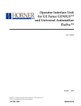
1
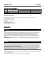
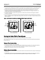
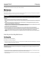
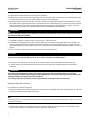
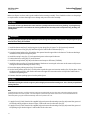
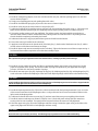
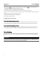
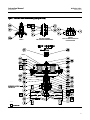
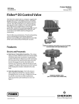
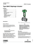
Instruction Manual D3 FloPro Valve D103221X012 February 2014 Fisherr D3 FloPro Control Valve Contents Introduction . . . . . . . . . . . . . . . . . . . . . . . . . . . . . . . . . 1 Scope of Manual . . . . . . . . . . . . . . . . . . . . . . . . . . . . . 1 Description . . . . . . . . . . . . . . . . . . . . . . . . . . . . . . . . . 1 Specifications . . . . . . . . . . . . . . . . . . . . . . . . . . . . . . . 2 Educational Services . . . . . . . . . . . . . . . . . . . . . . . . . 3 Installation . . . . . . . . . . . . . . . . . . . . . . . . . . . . . . . . . . 3 Setting the Valve FloPro Flow Adjuster . . . . . . . . . . . . 4 Maintenance . . . . . . . . . . . . . . . . . . . . . . . . . . . . . . . . . 5 Valve Plug and Seat Ring Maintenance . . . . . . . . . . 5 Packing Maintenance . . . . . . . . . . . . . . . . . . . . . . . . 10 Servicing the Actuator . . . . . . . . . . . . . . . . . . . . . . . 12 Changing Actuator Action . . . . . . . . . . . . . . . . . . . . 20 Parts Ordering . . . . . . . . . . . . . . . . . . . . . . . . . . . . . . . 20 Parts Kits . . . . . . . . . . . . . . . . . . . . . . . . . . . . . . . . . . . 23 Parts List . . . . . . . . . . . . . . . . . . . . . . . . . . . . . . . . . . . 23 Figure 1. Fisher D3 FloPro Control Valve NPS 2 RF Flanged End Connection W9249 Introduction Scope of Manual This instruction manual provides installation, maintenance, and parts information for the Fisher D3 FloPro control valve and actuator. Do not install, operate, or maintain D3 FloPro valves without being fully trained and qualified in valve, actuator, and accessory installation, operation, and maintenance. To avoid personal injury or property damage, it is important to carefully read, understand, and follow all the contents of this manual, including all safety cautions and warnings. If you have any questions about these instructions, contact your Emerson Process Management sales office before proceeding. Description The D3 FloPro control valve (figure 1) is a compact, rugged valve designed for on-off control of a variety of fluids at pressures up to 155 bar (2250 psig). This valve is ideal for use as a dump valve on gas separators and scrubbers. It is also well suited for other high pressure applications in natural gas production, compression, and processing. NPS 1 and NPS 2 D3 FloPro control valves are available in CL900 NPT end connections and CL600 raised face flanged end connections. www.Fisher.com Instruction Manual D3 FloPro Valve D103221X012 February 2014 Table 1. Specifications Valve Body Sizes and End Connection Styles(1) See table 3 Maximum Travel Maximum Inlet Pressures and Temperatures(1) Material Temperature Capabilities(1) VALVE BODY SIZE MAXIMUM INLET PRESSURE bar (psig) 15 mm (0.6 inch) Valve Body Assembly: Standard O-Ring: -40 to 135C (-40 to 275F) TEMPERATURE RANGE _C (_F) NPS 1 and NPS 2 NPT CL900 155 (2250) -46 to 93 (-50 to 200) 150 (2185) 93 to 149 (200 to 300) NPS 1 and NPS 2 RF CL600 103 (1500) -46 to 93 (-50 to 200) 100 (1455) 93 to 149 (200 to 300) Actuator Assembly: -34 to 82C (-30 to 180F) Flow Direction Flow Up or Flow Down Available Actuator Configurations Maximum Shutoff Pressure Drops(1) Spring-to-Open Spring-to-Close See table 2 Shutoff Classification per ANSI/FCI 70-2 and IEC 60534-4 Class IV Maximum Actuator Casing Pressure(1) 3.4 bar (50 psig) Flow Characteristic / Valve Plug Style Equal percentage / Micro-Form Valve Plug Actuator Diaphragm Effective Area Port Diameters See table 3 Actuator Pressure Connections 329 cm2 (51 square inches) 1/4 NPT internal 1. The pressure or temperature limits in the referenced tables and any applicable ASME code limitations should not be exceeded. Specifications Table 1 lists specifications for the D3 FloPro control valve. Some of the specifications for a given control valve as it originally comes from the factory are stamped on a nameplate located on the upper diaphragm casing. Table 2. Fisher D3 Maximum Shutoff Pressure Drops FLOW DIRECTION ACTUATOR ACTION Spring-to-Close Up Spring-to-Open Spring-to-Close Down Spring-to-Open 2 INPUT SIGNAL psi NUMBER OF SPRINGS 0.375 0.75 1.00 0-20 3 2250 544 341 0-35 6 2250 1504 999 0-20 2 2250 935 608 0-35 2 2250 2250 2094 0-20 2 1558 1800 950 0-35 3 2250 2250 2250 0-20 2 2250 1700 939 0-35 3 2250 2250 1575 MAXIMUM nP (PSI) PER PORT SIZE (INCH) Instruction Manual D3 FloPro Valve D103221X012 February 2014 Table 3. Valve Sizes and Connection Styles VALVE SIZE, NPS 1 PORT DIAMETER, (INCHES) 2 THREADED RAISED FACE (RF) FLANGED CL900 CL600 0.375, 0.75, 1 X X 0.375, 0.75, 1 X X X = Available construction. Educational Services For information on available courses for Fisher D3 valves, as well as a variety of other products, contact: Emerson Process Management Educational Services - Registration P.O. Box 190 Marshalltown, IA 50158-2823 Phone: 800-338-8158 or 641-754-3771 FAX: 641-754-3431 e-mail: [email protected] Installation WARNING Always wear protective gloves, clothing, and eyewear when performing any installation operations to avoid personal injury. To avoid personal injury or property damage caused by bursting of pressure-retaining parts or by uncontrolled process fluid, be certain the service conditions do not exceed the limits shown on the valve nameplate and in table 1. Use pressure-relieving devices required by government or accepted industry codes and good engineering practices. Check with your process or safety engineer for any additional measures that must be taken to protect against process media. If installing into an existing application, also refer to the WARNING at the beginning of the Maintenance section in this instruction manual. CAUTION When ordered, the valve configuration and construction materials were selected to meet particular pressure, temperature, pressure drop, and controlled fluid conditions. Responsibility for the safety of process media and compatibility of valve materials with process media rests solely with the purchaser and end-user. Since some body/trim material combinations are limited in their pressure drop and temperature ranges, do not apply any other conditions to the valve without first contacting your Emerson Process Management sales office. To avoid product damage, inspect the valve before installation for any damage or any foreign material that may have collected in the valve body. Also remove any pipe scale, welding slag, or other foreign material from the pipeline. 1. Before installing the control valve assembly, inspect it for any damage and for any foreign material that may have collected in the valve body. 2. Clean out all pipelines to remove scale, welding slag, and other foreign materials. 3 Instruction Manual D3 FloPro Valve D103221X012 February 2014 3. The control valve assembly may be installed in any orientation, but normally the actuator is vertical above the valve. Install the valve so the flow direction arrow on the side of the valve indicates the direction of the process flow. 4. Install the valve following local and national piping codes when they apply to the application. For screwed connections, treat the external pipe threads with a good grade pipe compound. For flanged connections, use suitable gaskets between valve and pipeline flanges. 5. If continuous operation is required during inspection or maintenance, install a three-valve bypass around the control valve assembly. 6. Connect loading pressure for the Spring-to-Close configuration to the lower casing assembly (key 21) as shown in figure 7. The Spring-to-Open configuration loading pressure connection is in the upper casing assembly (key 32) as shown in figure 8. Figure 2. FloPro Adjusts to Vary Flow Capacity (Shown with Valve Plug in Seated Position) 100% 100% 50% 50% CLOSED CLOSED FULL CAPACITY SETTING (FACTORY SET) 15 mm (0.6 INCH) TRAVEL REDUCED CAPACITY SETTING 10 mm (0.4 INCH) TRAVEL Setting the Valve FloPro Flow Adjuster The flow setting may only be adjusted if the 0.375 and 0.75 inch port sizes are installed. When shipped from the factory, the actuator has the FloPro flow adjuster set at the maximum flow rate position for the given port size. Spring-to-Close Actuator Action 1. Ensure the valve plug is in the seated position. 2. To change the valve flow rate, loosen the flow adjuster socket head cap screws (key 15), and reposition the flow adjuster halves (key 13 and 14) to the desired flow rate position. See figure 2 for flow rate settings. 3. Retighten the socket head screws (key 15) to 3 NSm (26 lbfSin). Spring-to-Open Actuator Action 1. Attach a pressure line to the actuator. Pressurize the actuator to a maximum of 2.41 bar (35 psi) to seat the plug in the seat ring. 2. To change the valve flow rate, loosen the flow adjuster socket head cap screws (key 15), and reposition the flow adjuster halves (key 13 and 14) to the desired flow rate position. See figure 2 for flow rate settings. 4 Instruction Manual D103221X012 D3 FloPro Valve February 2014 3. Retighten the socket head screws (key 15) to 3 NSm (26 lbfSin). Maintenance Refer to figures 7 and 8. Valve parts are subject to normal wear and must be inspected and replaced as necessary. The frequency of inspection and maintenance depends on the severity of the service conditions. WARNING Avoid personal injury from sudden release of process pressure or bursting of parts. Before performing any maintenance operations: D Do not remove the actuator from the valve while the valve is still pressurized. D Always wear protective gloves, clothing, and eyewear when performing any maintenance operations to avoid personal injury. D Disconnect any operating lines providing air pressure, electric power, or a control signal to the actuator. Be sure the actuator cannot suddenly open or close the valve. D Use bypass valves or completely shut off the process to isolate the valve from process pressure. Relieve process pressure on both sides of the valve. Drain the process media from both sides of the valve. D Vent the power actuator loading pressure. D Use lock-out procedures to be sure that the above measures stay in effect while you work on the equipment. D The valve packing box may contain process fluids that are pressurized, even when the valve has been removed from the pipeline. Process fluids may spray out under pressure when removing the packing hardware or packing rings. D Check with your process or safety engineer for any additional measures that must be taken to protect against process media. Valve Plug and Seat Ring Maintenance Trim Disassembly Spring-to-Close (Air-to-Open) Key numbers are referenced in figure 7. 1. Isolate the control valve from the line pressure, release pressure from both sides of the valve body (key 1), and drain the process media from both sides of the valve. CAUTION The following steps are intended to prevent damage to the valve plug (key 3) and seat ring (key 2) during the removal of the bonnet and actuator. 2. Pressurize the actuator to a maximum of 2.41 bar (35 psi) to stroke the valve to mid travel. This will raise the valve plug (key 3) off its seat and expose all of the serrations on the valve stem (key 16). 3. Loosen the hex socket head cap screws (key 15) and lower the flow adjuster (keys 13 and 14) to its lowest position on the valve stem. 5 D3 FloPro Valve Instruction Manual February 2014 D103221X012 4. Tighten the hex socket head cap screws to 3 NSm (26 lbfSin). 5. Relieve pressure to the actuator, shut off all pressure lines to the actuator, and disconnect. Use lockout procedures to ensure the above measures stay in effect while you work on the equipment. 6. Break the bonnet nut (key 5) loose with a hammer. Continue turning the bonnet nut by using a hammer or a large adjustable wrench, tightened around one ear of the bonnet nut. If the bonnet (key 7) is stuck in the valve, continue to unscrew the bonnet nut. The bonnet nut will contact the spring pins (or pipe plugs) (key 6, figures 7 or 8) and jack the bonnet out of the valve. Carefully lift the actuator assembly from the valve body. WARNING The spring pins/pipe plugs (key 6) must always be in place during valve operation. They provide a safeguard against injury when the unit is being disassembled. 7. Completely remove the packing retainer (key 8) using a 1-1/8 inch wrench. 8. Remove the valve plug by driving out the pin (key 43) and unscrewing the valve plug from the stem. Utilize a 1/8 inch drift punch in the holes provided on the stem to keep the stem from turning as the plug is removed. Do not remove the Belleville springs (key 9) from the stem, in order to retain the Belleville stacking orientation as shown in figure 3. 9. Use a 1-3/16 inch socket wrench to loosen and remove the seat ring (key 2). CAUTION Inspect the seat ring and valve body interior for wear, erosion, or damage in the following steps. 10. Inspect the seat ring for wear or damage. If the seating surface has been damaged, discard the seat ring. 11. Visually inspect the valve body interior below the seat ring for erosion or damage. Replace the valve body if necessary. WARNING Be careful to avoid damaging the seating surface on the valve plug or seat ring as damage in these areas will allow excessive leakage at shutoff. Avoid damaging the highly polished valve stem surface. A damaged valve stem could cut the packing and allow process fluid to leak to the atmosphere. Cover the opening in the valve body to prevent foreign material from getting into the valve body cavity. Spring-to-Open (Air-to-Close) Key numbers are referenced in figure 8. 1. Isolate the control valve from the line pressure, release pressure from both sides of the valve body (key 1), and drain the process media from both sides of the valve. Note The following steps are intended to ensure the groove pin is fully exposed below the bonnet to allow you to remove the pin before removing the valve plug. 2. Pressurize the actuator to a maximum of 2.41 bar (35 psi) to stroke the valve fully closed. This will seat the valve plug (key 3) and expose the top of the serrations on the valve stem (key 16). 6 Instruction Manual D3 FloPro Valve D103221X012 February 2014 3. Loosen the hex socket head cap screws (key 15) and raise the flow adjustor (keys 13 and 14) to its highest position on the valve stem. 4. Tighten the hex socket head cap screws to 3 NSm (26 lbfSin). 5. Relieve pressure to the actuator and disconnect the air lines. Ensure the flow adjustor is touching the top of the bonnet window. Use lockout procedures to ensure the above measures stay in effect while you work on the equipment. 6. Break the bonnet nut (key 5) loose with a hammer. Continue turning the bonnet nut by using a hammer or a large adjustable wrench, tightened around one ear of the bonnet nut. If the bonnet (key 7) is stuck in the valve, continue to unscrew the bonnet nut. The bonnet nut will contact the spring pins (or pipe plugs) (key 6, figures 7 or 8) and jack the bonnet out of the valve. Carefully lift the actuator assembly from the valve body. WARNING The spring pins/pipe plugs (key 6) must always be in place during valve operation. They provide a safeguard against injury when the unit is being disassembled. 7. Completely remove the packing retainer (key 8) using a 1-1/8 inch wrench. 8. Remove the valve plug by driving out the pin (key 43) and unscrewing the valve plug from the stem. Utilize a 1/8 inch drift punch in the holes provided on the stem to keep the stem from turning as the plug is removed. Do not remove the Belleville springs (key 9) from the stem, in order to retain the Belleville stacking orientation as shown in figure 3. 9. Use a 1-3/16 inch socket wrench to loosen and remove the seat ring (key 2). CAUTION Inspect the seat ring and valve body interior for wear, erosion, or damage in the following steps. 10. Inspect the seat ring for wear or damage. If the seating surface has been damaged, discard the seat ring. 11. Visually inspect the valve body interior below the seat ring for erosion or damage. Replace the valve body if necessary. WARNING Be careful to avoid damaging the seating surface on the valve plug or seat ring as damage in these areas will allow excessive leakage at shutoff. Avoid damaging the highly polished valve stem surface. A damaged valve stem could cut the packing and allow process fluid to leak to the atmosphere. Cover the opening in the valve body to prevent foreign material from getting into the valve body cavity. Trim Assembly Spring-to-Close (Air-to-Open) 1. Ensure the threads of the valve stem (key 16) and valve plug (key 3) are clean and free of debris. 2. Make sure the Belleville springs (key 9) are properly installed on the valve stem, as shown in figure 3. 3. Install the valve plug on the stem and insert a new pin (key 43). 4. Lubricate the threads of the packing retainer with anti-seize and install into the bonnet using a 1-1/8 inch wrench. Make sure the Belleville springs (key 9) are completely enclosed by the packing retainer as shown in figure 4. 5. Torque the packing retainer to 81 NSm (60 lbfSft). The packing retainer has been installed correctly when a metal-to-metal contact has been made between the packing retainer end and the bonnet (key 7). The packing retainer threads should be completely enclosed by the bonnet. 7 Instruction Manual D3 FloPro Valve D103221X012 February 2014 Figure 3. Packing and Belleville Spring Stacking Order UPPER PACKING SPACER (KEY 12) ANTI-EXTRUSION WASHER (KEY 10) FEMALE PACKING ADAPTER (KEY 11) PACKING RING (KEY 11) MALE PACKING ADAPTER (KEY 11) ANTI-EXTRUSION WASHER (KEY 10) LOWER PACKING SPACER (KEY 12) BELLEVILLE SPRINGS (KEY 9) PIN (KEY 43) VALVE PLUG (KEY 3) VALVE PLUG INSTALLED WITHOUT PACKING RETAINER Figure 4. Packing and Belleville Spring Stacking Order UNTIGHTENED, NOTE THE GAP FULLY TIGHTENED, NO GAP PACKING RETAINER (KEY 8) BELLEVILLE SPRINGS FULLY ENCLOSED BY THE PACKING RETAINER 8 VALVE PLUG, BELLEVILLE SPRINGS, AND PACKING RETAINER CORRECTLY INSTALLED AND TIGHTENED Instruction Manual D3 FloPro Valve D103221X012 February 2014 Figure 5. Lubrication Locations on Packing FEMALE PACKING ADAPTER PACKING RING MALE PACKING ADAPTER LUBRICATE WITH 3mm (1/8 INCH BEAD) OF SUPPLIED HIGH PERFORMANCE FLUORINATED GREASE (KEY 44) LUBRICATE WITH 3mm (1/8 INCH BEAD) OF SUPPLIED HIGH PERFORMANCE FLUORINATED GREASE 6. Thoroughly clean the seat ring (key 2) threads and the mating threads in the valve body (key 1). 7. Apply anti-seize lubricant to the threads of the seat ring and its mating threads in the valve body. 8. Screw the seat ring into the valve body. Use a 1-3/16 inch socket wrench to tighten the seat ring to 170 NSm (125 lbfSft). Remove all excess lubricant after tightening. 9. Lubricate the bonnet O-ring (key 4) with lithium grease and install on the bonnet. 10. Apply anti-seize lubricant to the threads on the valve body and bonnet nut (key 5) and the contact surfaces of the bonnet and bonnet nut flange. Install the bonnet and actuator assembly onto the valve body. Tighten the bonnet nut until the nut stops turning. A few hammer blows will be required to ensure that the assembly is tight. 11. Pressurize the actuator to a maximum of 2.41 bar (35 psi) to stroke the valve to mid travel. 12. Loosen the hex socket head cap screws (key 15) and remove the flow adjuster (keys 13 and 14). 13. Relieve pressure to the actuator to fully close the valve. 14. Make sure the valve is fully seated and install the flow adjustor (keys 13 and 14) and hex socket head cap screws (key 15). 15. Set the desired flow rate position according to figure 2. 16. Tighten the hex socket head cap screws to 3 NSm (26 lbfSin). Spring-to-Open (Air-to-Close) 1. Ensure the threads of the valve stem (key 16) and valve plug (key 3) are clean and free of debris. 2. Make sure the Belleville springs (key 9) are properly installed on the valve stem, as shown in figure 3. 3. Install the valve plug on the stem and insert a new pin (key 43). 4. Lubricate the threads of the packing retainer with anti-seize and install into the bonnet using a 1-1/8 inch wrench. Make sure the Belleville springs (key 9) are completely enclosed by the packing retainer as shown in figure 4. 5. Torque the packing retainer to 81 NSm (60 lbfSft). The packing retainer has been installed correctly when a metal to metal contact has been made between the packing retainer end and the bonnet (key 7). The packing retainer threads should be completely enclosed by the bonnet. 6. Thoroughly clean the seat ring (key 2) threads and the mating threads in the valve body (key 1). 7. Apply anti-seize lubricant to the threads of the seat ring and its mating threads in the valve body. 8. Screw the seat ring into the valve body. Use a 1-3/16 inch socket wrench to tighten the seat ring to 170 NSm (125 lbfSft). Remove all excess lubricant after tightening. 9 D3 FloPro Valve Instruction Manual February 2014 D103221X012 9. Lubricate the bonnet O-ring (key 4) with lithium grease and install on the bonnet. 10. Apply anti-seize lubricant to the threads on the valve body and bonnet nut (key 5) and the contact surfaces of the bonnet and bonnet nut flange. Install the bonnet and actuator assembly onto the valve body. Tighten the bonnet nut until the nut stops turning. A few hammer blows will be required to ensure that the assembly is tight. 11. Pressurize the actuator to a maximum of 2.41 bar (35 psi) to stroke the valve fully closed. 12. Loosen the hex socket head cap screws (key 15) and set the desired flow rate position according to figure 2. 13. Tighten the hex socket head cap screws to 3 NSm (26 lbfSin). 14. Relieve pressure to the actuator. Packing Maintenance WARNING Observe the warning at the start of the Maintenance section. Key numbers are referenced in figure 3. The valve stem packing can only be serviced by removing the bonnet from the valve body. Packing Disassembly Spring-to-Close (Air-to-Open) 1. Disassemble the valve per steps 1 - 8 in the Spring-to-Close Trim Disassembly section of the Valve Plug and Seat Ring Maintenance section of this manual. 2. Remove the five Belleville springs (key 9), lower packing spacer (key 12), packing set (key 11), and two anti-extrusion washers (key 10) from the bonnet (key 7) using a formed wire hook. 3. Clean and inspect the packing box wall to ensure that the packing surfaces are not damaged. If the surface condition is damaged and cannot be improved by light sanding, replace the bonnet. 4. Inspect the valve stem (key 16) and valve plug (key 3) for scratches or wear and replace if necessary. Spring-to-Open (Air-to-Close) 1. Disassemble the valve per steps 1 - 8 in the Spring-to-Open Trim Disassembly section of the Valve Plug and Seat Ring Maintenance section of this manual. 2. Remove the five Belleville springs (key 9), lower packing spacer (key 12), packing set (key 11), and two anti-extrusion washers (key 10) from the bonnet (key 7) using a formed wire hook. 3. Clean and inspect the packing box wall to ensure that the packing surfaces are not damaged. If the surface condition is damaged and cannot be improved by light sanding, replace the bonnet. 4. Inspect the valve stem (key 16) and valve plug (key 3) for scratches or wear and replace if necessary. Packing Assembly The following steps define the proper procedure for installing the packing in a D3 FloPro Control Valve. Improper packing assembly can lead to poor valve performance. The proper packing arrangement is shown in figure 3. Spring-to-Close (Air-to-Open) 1. Ensure the upper packing spacer (key 12) is installed. 10 Instruction Manual D103221X012 D3 FloPro Valve February 2014 2. Use the lower packing spacer (key 12) and a tube to push the upper anti-extrusion washer (key 10) into place. Using the lower packing spacer in this manner will ensure the upper anti-extrusion washer is fully seated and flat when installed in the packing bore. 3. Remove the lower packing spacer from the packing bore. CAUTION All D3 FloPro packing kits include a single use packet of high performance fluorinated grease. This is the only acceptable D3 packing lubricant. Note In the following procedure, carefully install each packing ring individually over the valve stem and push completely into the packing box with a non-marring tube. A 12-inch length of 1/2 inch PVC pipe works well for this. It is recommended that the lubricated packing rings be installed individually rather than pushed in as a set. 4. Apply a 3mm (1/8 inch) bead of the supplied high performance fluorinated grease (key 44) around the groove of the female packing adaptor as shown in figure 5 and install over the valve stem (key 16). 5. Apply a 3mm (1/8 inch) bead of the supplied high performance fluorinated grease (key 44) around the groove of the packing ring as shown in figure 5 and install over the valve stem. 6. Install the male packing adaptor, lower anti-extrusion washer (key 10), and lower packing spacer over the valve stem as shown in figure 3. 7. Firmly press all packing parts into the packing bore with a tube. 8. Install the five Belleville springs (key 9) over the valve stem as shown in figure 3. 9. Install the valve plug (key 3) on the stem and insert a new groove pin (key 43). 10. Lubricate the threads of the packing retainer with anti-seize and install into the bonnet using a 1-1/8 inch wrench. Make sure the Belleville springs are completely enclosed by the packing retainer as shown in figure 4. 11. Torque the packing retainer to 81 NSm (60 lbfSft). The packing retainer has been installed correctly when a metal-to-metal contact has been made between the packing retainer end and the bonnet (key 7). The packing retainer threads should be completely enclosed by the bonnet. 12. Assemble the valve per steps 9 - 16 in the Spring-to-Close Trim Assembly section of the Valve Plug and Seat Ring Maintenance section of this manual. Spring-to-Open (Air-to-Close) 1. Ensure the upper packing spacer (key 12) is installed. 2. Use the lower packing spacer (key 12) and a tube to push the upper anti-extrusion washer (key 10) into place. Using the lower packing spacer in this manner will ensure the upper anti-extrusion washer is fully seated and flat when installed in the packing bore. 3. Remove the lower packing spacer from the packing bore. CAUTION All D3 FloPro packing kits include a single use packet of high performance fluorinated grease. This is the only acceptable D3 packing lubricant. Note In the following procedure, carefully install each packing ring individually over the valve stem and push completely into the packing box with a non-marring tube. A 12-inch length of 1/2 inch PVC pipe works well for this. It is recommended that the lubricated packing rings be installed individually rather than pushed in as a set. 11 D3 FloPro Valve February 2014 Instruction Manual D103221X012 4. Apply a 3mm (1/8 inch) bead of the supplied high performance fluorinated grease (key 44) around the groove of the female packing adaptor as shown in figure 5 and install over the valve stem (key 16). 5. Apply a 3mm (1/8 inch) bead of the supplied high performance fluorinated grease (key 44) around the groove of the packing ring as shown in figure 5 and install over the valve stem. 6. Install the male packing adaptor, lower anti-extrusion washer (key 10), and lower packing spacer over the valve stem as shown in figure 3. 7. Firmly press all packing parts into the packing bore with a tube. 8. Install the five Belleville springs (key 9) over the valve stem as shown in figure 3. 9. Install the valve plug (key 3) on the stem and insert a new groove pin (key 43). 10. Lubricate the threads of the packing retainer with anti-seize and install into the bonnet using a 1-1/8 inch wrench. Make sure the Belleville springs are completely enclosed by the packing retainer as shown in figure 4. 11. Torque the packing retainer to 81 NSm (60 lbfSft). The packing retainer has been installed correctly when a metal-to-metal contact has been made between the packing retainer end and the bonnet (key 7). The packing retainer threads should be completely enclosed by the bonnet. 12. Assemble the valve per steps 9 - 14 in the Spring-to-Open Trim Assembly section of the Valve Plug and Seat Ring Maintenance section of this manual. Servicing the Actuator The D3 FloPro valve is equipped with a spring and diaphragm actuator. The actuator action may be reversed without the need for additional parts. The number of springs contained in the actuator may have to be adjusted according to actuator action and/or supply pressure. Refer to table 2 for the proper number of springs for your actuator action and valve service conditions. Actuator Disassembly Spring-to-Close (Air-to-Open) Key numbers are referenced in figure 7. WARNING Observe the warning at the start of the Maintenance section. Inspect all parts for wear or damage during disassembly. Replace any worn or damaged parts with genuine Fisher replacement parts. If the diaphragm is replaced, a new diaphragm O-ring should also be installed. 1. Isolate the control valve from the line pressure, release pressure from both sides of the valve body (key 1), and drain the process media from both sides of the valve. WARNING To prevent possible personal injury or property damage from removing the casing cap screws in the wrong sequence, follow the procedure as outlined below for removing the upper casing. Be aware as you loosen and remove the actuator casing cap screws that the actuator springs are under compression. 12 Instruction Manual D103221X012 D3 FloPro Valve February 2014 2. Remove the ten short actuator casing cap screws (key 29). 3. Remove the two long actuator casing cap screws (key 31) by alternating between them as you loosen them. Keep the upper casing (key 32) level during this procedure. 4. Remove the upper casing and the springs (key 28). 5. Remove the stem nut (key 27) taking care not turn the valve stem (key 16). Keep the valve stem from turning by inserting a 1/8 inch drift punch in the holes provided on the valve stem. 6. Remove the actuator spacer (key 26), diaphragm O-ring (key 19), diaphragm plate (key 24), diaphragm (key 23), and the diaphragm washer (key 22). 7. Remove the bonnet locknut (key 20) with a 1-1/2 inch socket wrench and lift off the lower casing (key 21). 8. Remove the casing O-ring (key 17). 9. Break the bonnet nut (key 5) loose with a hammer. Continue turning the bonnet nut by using a hammer or a large adjustable wrench, tightened around one ear of the bonnet nut. If the bonnet (key 7) is stuck in the valve, continue to unscrew the bonnet nut. The bonnet nut will contact the spring pins (or pipe plugs) (key 6, figures 7 or 8) and jack the bonnet out of the valve. Carefully lift the actuator assembly from the valve body. WARNING The spring pins/pipe plugs (key 6) must always be in place during valve operation. They provide a safeguard against injury when the unit is being disassembled. 10. Completely remove the packing retainer (key 8) using a 1-1/8 inch wrench. 11. Remove the valve plug (key 3) by driving out the pin (key 43) and unscrewing the valve plug from the stem. Utilize a 1/8 inch drift punch in the holes provided on the stem to keep the stem from turning as the plug is removed. 12. Remove the five Belleville springs (key 9), lower packing spacer (key 12), packing set (key 11), and two anti-extrusion washers (key 10) from the bonnet using a formed wire hook. 13. Completely remove the flow adjuster (keys 13, 14, and 15) from the valve stem. 14. Remove the valve stem from the top of the bonnet. CAUTION The valve stem must be removed to replace the stem O-ring and the bonnet bushing. If the valve stem is removed, the valve packing must be replaced since the threads on the valve stem may damage the packing when the valve stem is removed. 15. Remove the stem O-ring (key 25) and the bonnet bushing (key 18). 16. If the hammer nut needs to be removed from the bonnet, the spring pins (or pipe plugs) (key 6, figures 7 or 8) can be removed with locking pliers. Spring-to-Open (Air-to-Close) Key numbers are referenced in figure 8. WARNING Observe the warning at the start of the Maintenance section. 13 D3 FloPro Valve February 2014 Instruction Manual D103221X012 Inspect all parts for wear or damage during disassembly. Replace any worn or damaged parts with genuine Fisher replacement parts. If the diaphragm is replaced, a new diaphragm O-ring should also be installed. 1. Isolate the control valve from the line pressure, release pressure from both sides of the valve body (key 1), and drain the process media from both sides of the valve. 2. Remove the ten short actuator casing cap screws (key 29) and the two long actuator casing cap screws (key 31). 3. Remove the upper casing (key 32). 4. Lubricate the threads above the stem nut (key 27) with anti-seize lubricant to prevent galling of the threads. WARNING To prevent possible personal injury or property damage, be aware as you loosen and remove the stem nut that the actuator springs are under compression. 5. Relieve spring tension by slowly removing the stem nut. Do not allow the valve stem (key 16) to turn while removing the stem nut. Keep the valve stem from turning by inserting a 1/8 inch drift punch in the holes provided on the valve stem. 6. Remove the diaphragm washer (key 22), diaphragm (key 23), diaphragm plate (key 24), diaphragm O-ring (key 19), and actuator spacer (key 26). 7. Remove the bonnet locknut (key 20) with a 1-1/2 inch socket wrench and lift off the lower casing (key 21). 8. Remove the casing O-ring (key 17). 9. Break the bonnet nut (key 5) loose with a hammer. Continue turning the bonnet nut by using a hammer or a large adjustable wrench, tightened around one ear of the bonnet nut. If the bonnet (key 7) is stuck in the valve, continue to unscrew the bonnet nut. The bonnet nut will contact the spring pins (or pipe plugs) (key 6, figures 7 or 8) and jack the bonnet out of the valve. Carefully lift the actuator assembly from the valve body. WARNING The spring pins/pipe plugs (key 6) must always be in place during valve operation. They provide a safeguard against injury when the unit is being disassembled. 10. Completely remove the packing retainer (key 8) using a 1-1/8 inch wrench. 11. Remove the valve plug (key 3) by driving out the pin (key 43) and unscrewing the valve plug from the stem. Utilize a 1/8 inch drift punch in the holes provided on the stem to keep the stem from turning as the plug is removed. 12. Remove the five Belleville springs (key 9), lower packing spacer (key 12), packing set (key 11), and two anti-extrusion washers (key 10) from the bonnet using a formed wire hook. 13. Completely remove the flow adjuster (keys 13, 14, and 15) from the valve stem. 14. Remove the valve stem from the bottom of the bonnet (key 16). CAUTION The valve stem must be removed to replace the stem O-ring and the bonnet bushing. If the valve stem is removed, the valve packing must be replaced since the threads on the valve stem may damage the packing when the valve stem is removed. 14 Instruction Manual D3 FloPro Valve D103221X012 February 2014 Figure 6. Spring Locations As Seen From Above Lower Actuator Casing 6 SPRINGS 3 SPRINGS 2 SPRINGS 15. Remove the stem O-ring (key 25) and the bonnet bushing (key 18). 16. If the hammer nut needs to be removed from the bonnet, the spring pins (or pipe plugs) (key 6, figures 7 or 8) can be removed with locking pliers. Actuator Assembly Spring-to-Close (Air-to-Open) Key numbers are referenced in figure 7. The proper packing arrangement is shown in figure 3. CAUTION Avoid possible product damage in the following procedure by ensuring there are no burrs or sharp edges on any threads or surfaces which may damage internal valve components during assembly. Make sure all parts are clean and in good condition before starting assembly. There should be no burrs or sharp edges on any threads or surfaces that might cut or damage soft parts in the valve assembly. CAUTION The threads on factory-produced valve stems have been specially machined to avoid O-ring, bushing, or packing damage during trim maintenance. Use of other than a factory-produced valve stem may result in early stem O-ring, bushing, and packing failure. WARNING The spring pins/pipe plugs (key 6) must always be in place during valve operation. They provide a safeguard against injury when the unit is being disassembled. 1. Install the bonnet nut (key 5) and spring pins (or pipe plugs) (key 6, figures 7 or 8) if previously removed. 15 D3 FloPro Valve February 2014 Instruction Manual D103221X012 2. Lubricate the stem O-ring (key 25) with lithium grease and install in the bonnet (key 7). 3. Press the bonnet bushing (key 18) with the slots upward into the upper hole in the bonnet. The bonnet bushing is installed correctly when it snaps into place. 4. Install the casing O-ring (key 17) in the provided groove at the top of the bonnet. 5. Position the lower casing (key 21) on the bonnet. 6. Install the casing locknut (key 20) on the bonnet and torque to 203 NSm (150 lbfSft). 7. Install the valve stem (key 16) from the bottom of the bonnet. Inserting the valve stem in this manner will prevent damage to the bonnet bushing and stem O-ring. 8. Ensure the upper packing spacer (key 12) is installed. 9. Use the lower packing spacer (key 12) and a tube to push the upper anti-extrusion washer (key 10) into place. Using the lower packing spacer in this manner will ensure the upper anti-extrusion washer is fully seated and flat when installed in the packing bore. 10. Remove the lower packing spacer from the packing bore. CAUTION All D3 FloPro packing kits include a single use packet of high performance fluorinated grease. This is the only acceptable D3 packing lubricant. Note In the following procedure, carefully install each packing ring individually over the valve stem and push completely into the packing box with a non-marring tube. A 12-inch length of 1/2 inch PVC pipe works well for this. It is recommended that the lubricated packing rings be installed individually rather than pushed in as a set. 11. Apply a 3mm (1/8 inch) bead of the supplied high performance fluorinated grease (key 44) around the groove of the female packing adaptor as shown in figure 5 and install over the valve stem (key 16). 12. Apply a 3mm (1/8 inch) bead of the supplied high performance fluorinated grease (key 44) around the groove of the packing ring as shown in figure 5 and install over the valve stem. 13. Install the male packing adaptor, lower anti-extrusion washer (key 10), and lower packing spacer over the valve stem as shown in figure 3. 14. Firmly press all packing parts into the packing bore with a tube. 15. Install the five Belleville springs (key 9) over the valve stem as shown in figure 3. 16. Install the valve plug on the stem and insert a new pin (key 43). 17. Lubricate the threads of the packing retainer with anti-seize and install into the bonnet using a 1-1/8 inch wrench. Make sure the Belleville springs (key 9) are completely enclosed by the packing retainer as shown in figure 4. 18. Torque the packing retainer to 81 NSm (60 lbfSft). The packing retainer has been installed correctly when a metal-to-metal contact has been made between the packing retainer end and the bonnet. The packing retainer threads should be completely enclosed by the bonnet. 19. Lubricate the bonnet O-ring (key 4) with lithium grease and install onto the bonnet. 20. Ensure the seat ring is installed in the valve body. 21. Apply anti-seize lubricant on the threads of the valve body (key 1), the threads of the bonnet nut (key 5), and the contact surfaces of the bonnet and bonnet nut flange. 22. Install the bonnet and actuator assembly into the valve body. Tighten the bonnet nut until the nut stops turning. A few hammer blows will be required to ensure that the assembly is tight. 16 Instruction Manual D3 FloPro Valve D103221X012 February 2014 CAUTION Avoid possible product damage which may affect proper operation of the diaphragm. Ensure the washer is aligned with the hole in the diaphragm so the washer does not cut the diaphragm. 23. Install the diaphragm washer (key 22) over the valve stem threads with the lip facing upward. If you are unsure of the correct orientation for the diaphragm washer, see figure 7 view A for the correct orientation. 24. Install the diaphragm (key 23), diaphragm plate (key 24), diaphragm O-ring (key 19), and actuator spacer (key 26) on the valve stem. Position the diaphragm so the holes in the diaphragm align with the holes in the lower casing. 25. Lubricate the threads above the stem nut (key 27) with anti-seize lubricant to prevent galling of the threads. 26. Install the stem nut (key 27) and torque to 20 NSm (15 lbfSft). Use a 1/8 inch drift punch to keep the valve stem from turning as the hex nut is installed. CAUTION Non-symmetrical spring arrangement could cause actuator failure, resulting in possible product damage. 27. Install the correct number of springs (key 28) in a symmetrical pattern on the spring locators on the diaphragm plate. See figure 6 for the proper arrangement of the springs. The correct number of springs is dependent on your application and supply pressure. See table 2 for the correct number of springs. 28. Place the upper casing (key 32) on the diaphragm and lower casing. Position the upper casing so the holes in the upper casing align with the holes in the diaphragm and lower casing. CAUTION Do not lubricate cap screws (key 29 and 31). The following torque specifications are for unlubricated bolting. 29. Install the two long cap screws (key 31) opposite each other. Install the hex nuts (key 30) onto the long cap screws and tighten, alternating until the upper casing contacts the diaphragm. Keep the upper casing level during this process. 30. Install the ten short cap screws (key 29) into the remaining holes and install hex nuts on the remaining cap screws. 31. Torque the hex nuts in a crossing pattern to 16 NSm (12 lbfSft). 32. Make sure valve is fully seated and install the flow adjustor (keys 13 and 14) and hex socket head cap screws (key 15). 33. Set the desired flow rate position according to figure 2. 34. Tighten the hex socket head cap screws to 3 NSm (26 lbfSin). Spring-to-Open (Air-to-Close) Key numbers are referenced in figure 8. The proper packing arrangement is shown in figure 3. CAUTION Avoid possible product damage in the following procedure by ensuring there are no burrs or sharp edges on any threads or surfaces which may damage internal valve components during assembly. 17 D3 FloPro Valve February 2014 Instruction Manual D103221X012 Make sure all parts are clean and in good condition before starting assembly. There should be no burrs or sharp edges on any threads or surfaces that might cut or damage soft parts in the valve assembly. CAUTION The threads on factory-produced valve stems have been specially machined to avoid O-ring, bushing, or packing damage during trim maintenance. Use of other than a factory-produced valve stem may result in early stem O-ring, bushing, and packing failure. WARNING The spring pins/pipe plugs (key 6) must always be in place during valve operation. They provide a safeguard against injury when the unit is being disassembled. 1. Install the bonnet nut (key 5) and spring pins (or pipe plugs) (key 6, figures 7 or 8) if previously removed. 2. Lubricate the stem O-ring (key 25) with lithium grease and install in the bonnet (key 7). 3. Press the bonnet bushing (key 18) with the slots upward into the upper hole in the bonnet. The bonnet bushing is installed correctly when it snaps into place. 4. Install the casing O-ring (key 17) in the provided groove at the top of the bonnet. 5. Position the lower casing (key 21) on the bonnet. 6. Install the casing locknut (key 20) on the bonnet and torque to 203 NSm (150 lbfSft). 7. Install the valve stem (key 16) from the bottom of the bonnet. Inserting the valve stem in this manner will prevent damage to the bonnet bushing and stem O-ring. 8. Ensure the upper packing spacer (key 12) is installed. 9. Use the lower packing spacer (key 12) and a tube to push the upper anti-extrusion washer (key 10) into place. Using the lower packing spacer in this manner will ensure the upper anti-extrusion washer is fully seated and flat when installed in the packing bore. 10. Remove the lower packing spacer from the packing bore. CAUTION All D3 FloPro packing kits include a single use packet of high performance fluorinated grease. This is the only acceptable D3 packing lubricant. Note In the following procedure, carefully install each packing ring individually over the valve stem and push completely into the packing box with a non-marring tube. A 12-inch length of 1/2 inch PVC pipe works well for this. It is recommended that the lubricated packing rings be installed individually rather than pushed in as a set. 11. Apply a 3mm (1/8 inch) bead of the supplied high performance fluorinated grease (key 44) around the groove of the female packing adaptor as shown in figure 5 and install over the valve stem (key 16). 12. Apply a 3mm (1/8 inch) bead of the supplied high performance fluorinated grease (key 44) around the groove of the packing ring as shown in figure 5 and install over the valve stem. 18 Instruction Manual D3 FloPro Valve D103221X012 February 2014 13. Install the male packing adaptor, lower anti-extrusion washer (key 10), and lower packing spacer over the valve stem as shown in figure 3. 14. Firmly press all packing parts into the packing bore with a tube. 15. Install the five Belleville springs (key 9) over the valve stem as shown in figure 3. 16. Install the valve plug on the stem and insert a new pin (key 43). 17. Lubricate the threads of the packing retainer with anti-seize and install into the bonnet using a 1-1/8 inch wrench. Make sure the Belleville springs (key 9) are completely enclosed by the packing retainer as shown in figure 4. 18. Torque the packing retainer to 81 NSm (60 lbfSft). The packing retainer has been installed correctly when a metal-to-metal contact has been made between the packing retainer end and the bonnet. The packing retainer threads should be completely enclosed by the bonnet. 19. Lubricate the bonnet O-ring (key 4) with lithium grease and install onto the bonnet. 20. Ensure the seat ring is installed in the valve body. 21. Apply anti-seize lubricant on the threads of the valve body (key 1), the threads of the bonnet nut (key 5), and the contact surfaces of the bonnet and bonnet nut flange. 22. Install the bonnet and actuator assembly into the valve body. Tighten the bonnet nut until the nut stops turning. A few hammer blows will be required to ensure that the assembly is tight. CAUTION Non-symmetrical spring arrangement could cause actuator failure, resulting in possible product damage. 23. Install the correct number of springs (key 28) in a symmetrical pattern on the lower casing. See figure 6 for the proper arrangement of the springs. The correct number of springs is dependent on your application and supply pressure. See table 2 for the correct number of springs. 24. Install the actuator spacer (key 26), diaphragm O-ring (key 19), diaphragm plate (key 24), and diaphragm (key 23) on the valve stem. Position the diaphragm so the holes in the diaphragm align with the holes in the bottom casing. CAUTION Avoid possible product damage which may affect proper operation of the diaphragm. Ensure the washer is aligned with the hole in the diaphragm so the washer does not cut the diaphragm. 25. Install the diaphragm washer (key 22) over the valve stem threads with the lip facing downward. If you are unsure of the correct orientation for the diaphragm washer, see figure 8 view A for the correct orientation. Make sure the lip fits inside the diaphragm hole. 26. Lubricate the threads above the stem nut (key 27) with anti-seize lubricant to prevent galling of the threads. 27. Install the stem nut and torque to 20 NSm (15 lbfSft). Use a 1/8 inch drift punch to keep the valve stem from turning as the hex nut is installed. The springs will be compressed when the stem nut is fully tightened. 28. Place the upper casing (key 32) on the diaphragm and lower casing. Position the upper casing so the holes in the upper casing align with the holes in the diaphragm and lower casing. CAUTION Do not lubricate cap screws (key 29 and 31). The following torque specifications are for unlubricated bolting. 19 D3 FloPro Valve February 2014 Instruction Manual D103221X012 29. Install the two long cap screws (key 31) opposite each other. Install the ten short cap screws (key 29) into the remaining holes and install hex nuts (key 30) on all cap screws. 30. Torque the hex nuts in a crossing pattern to 16 NSm (12 lbfSft). 31. Pressurize the actuator to a maximum of 2.41 bar (35 psi) to stroke the valve fully closed. 32. Make sure valve is fully seated and install the flow adjustor (keys 13 and 14) and hex socket head cap screws (key 15). 33. Set the desired flow rate position according to figure 2. 34. Tighten the hex head screws to 3 NSm (26 lbfSin). 35. Relieve pressure to the actuator. Changing Actuator Action From Spring-to-Close to Spring-to-Open 1. Follow steps 1 to 6 in the Disassembly instructions for the Spring-to-Close actuator on page 12 of this manual. 2. Follow steps 23 to 34 in the Assembly instructions for the Spring-to-Open actuator on page 17 of this manual. From Spring-to-Open to Spring-to-Close 1. Follow steps 1 to 6 in the Disassembly instructions for the Spring-to-Open actuator on page 13 of this manual. 2. Follow steps 23 to 34 in the Assembly instructions for the Spring-to-Close actuator on page 17 of this manual. Parts Ordering Each D3 FloPro control valve is assigned a serial number, which can be found on the nameplate. Refer to the number when contacting your Emerson Process Management representative for assistance or when ordering replacement parts. WARNING Use only genuine Fisher replacement parts. Components that are not supplied by Emerson Process Management should not, under any circumstances, be used in any Fisher valve, because they may void your warranty, might adversely affect the performance of the valve, and could cause personal injury and property damage. 20 Instruction Manual D3 FloPro Valve D103221X012 February 2014 Figure 7. Fisher D3 FloPro Valve Assembly (Spring-to-Close) VIEW A BELLEVILLE SPRING AND PACKING ARRANGEMENT VIEW B KEY 6 ALTERNATE PIPE PLUG CONSTRUCTION VIEW A SEE VIEW B FOR ALTERNATE CONSTRUCTION GE21319-B APPLY LUBRICANT 21 Instruction Manual D3 FloPro Valve D103221X012 February 2014 Figure 8. Fisher D3 FloPro Valve Assembly (Spring-to-Open) VIEW A VIEW A SEE VIEW B FOR ALTER NATE CONSTRUCTION GE21338-B APPLY LUBRICANT 22 BELLEVILLE SPRING AND PACKING ARRANGEMENT VIEW B KEY 6 ALTERNATE PIPE PLUG CONSTRUCTION Instruction Manual D3 FloPro Valve D103221X012 February 2014 Parts Kits TRIM KITS Port Diameter (inches) 0.375 0.75 1 Standard trim kit (Contains keys 2, 3, 4, and 43) RD3STDX0012 RD3STDX0022 RD3STDX0032 Carbide trim kit (Contains keys 2, 3, 4, and 43) RD3CARBX042 RD3CARBX052 RD3CARBX062 ACTUATOR KIT Contains keys 17, 18, 19, 23, and 25 RD3X0000012 PACKING KIT Contains keys 4, 10, 11, 43, and 44 RD3PACKX012 GE18774X012 SPRING Key 28 BONNET O-RING Key 4 1P1676X0062 VALVE STEM Key 16 GE20615X012 Parts List Note Recommended spare parts are included in the Parts Kits shown at the top of this page. For additional information or for part numbers not shown, contact your Emerson Process Management sales office. Key Description 1 2* 3* 4* 5 6 7 8 9 10* 11* 12 13 14 15 Valve Body Seat Ring Valve Plug Bonnet O-ring Bonnet Nut Spring Pin (or alternate pipe plug) (2 req'd) Bonnet Packing Retainer Belleville Springs (5 req'd) Anti-Extrusion Washer (2 req'd) Packing Set Packing Spacer FloPro Half FloPro Half Hex Socket Head Cap Screw (2 req'd) *Recommended spare parts Key Description 16* 17* 18* 19* 20 21 22 23* 24 25* 26 27 28* 29 30 31 32 33 34 35 36 38 39 40 41 43* 44* Stem Casing O-ring Bonnet Bushing Diaphragm O-ring Locknut Lower Casing Diaphragm Washer Diaphragm Diaphragm Plate Stem O-ring Actuator Spacer Stem Nut Spring (quantity varies with application) Short Hex Head Cap Screw (10 req'd) Hex Nut (12 req'd) Long Hex Head Cap Screw (2 req'd) Upper Casing Vent Nameplate Spring Label Lubricant, lithium grease Lubricant, Anti-Seize Protector Cap (2 req'd) Flow Arrow Drive Screw (2 req'd) Groove Pin High Performance Fluorinated Grease Packing Lubricant 23 D3 FloPro Valve February 2014 Instruction Manual D103221X012 Neither Emerson, Emerson Process Management, nor any of their affiliated entities assumes responsibility for the selection, use or maintenance of any product. Responsibility for proper selection, use, and maintenance of any product remains solely with the purchaser and end user. Fisher is a mark owned by one of the companies in the Emerson Process Management business unit of Emerson Electric Co. Emerson Process Management, Emerson, and the Emerson logo are trademarks and service marks of Emerson Electric Co. All other marks are the property of their respective owners. The contents of this publication are presented for informational purposes only, and while every effort has been made to ensure their accuracy, they are not to be construed as warranties or guarantees, express or implied, regarding the products or services described herein or their use or applicability. All sales are governed by our terms and conditions, which are available upon request. We reserve the right to modify or improve the designs or specifications of such products at any time without notice. Emerson Process Management Marshalltown, Iowa 50158 USA Sorocaba, 18087 Brazil Chatham, Kent ME4 4QZ UK Dubai, United Arab Emirates Singapore 128461 Singapore www.Fisher.com 24 E 2006, 2014 Fisher Controls International LLC. All rights reserved.