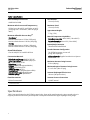
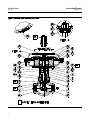
1
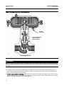
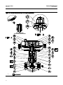
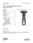
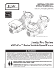
Instruction Manual D2 FloPro Valve D103031X012 June 2011 Fisherr D2 FloPro Control Valve Contents Figure 1. Fisher D2 FloPro Control Valve Introduction . . . . . . . . . . . . . . . . . . . . . . . . . . . . . . . . . 1 Scope of Manual . . . . . . . . . . . . . . . . . . . . . . . . . . . . . 1 Description . . . . . . . . . . . . . . . . . . . . . . . . . . . . . . . . . 1 Specifications . . . . . . . . . . . . . . . . . . . . . . . . . . . . . . . 2 Installation . . . . . . . . . . . . . . . . . . . . . . . . . . . . . . . . . . 3 Setting Valve FloPro Flow Adjuster . . . . . . . . . . . . . . 4 Changing Actuator Action from (Air-to-Open) to (Air-to-Close) . . . . . . . . . . . . . . . 4 Maintenance . . . . . . . . . . . . . . . . . . . . . . . . . . . . . . . . . 5 Valve Trim Maintenance . . . . . . . . . . . . . . . . . . . . . . 6 Packing, Valve Trim, and Actuator Maintenance . . . . . . . . . . . . . . . . . . . . . 7 Parts Kits . . . . . . . . . . . . . . . . . . . . . . . . . . . . . . . . . . . 14 Parts List . . . . . . . . . . . . . . . . . . . . . . . . . . . . . . . . . . . 14 Appendix A (Packing Constructions with Lot Numbers Less Than 0410-xxxx) . . . . . . . . . 17 W9235-1 Introduction Scope of Manual This instruction manual provides installation, maintenance, and parts information for the NPS 1 Fisher D2 FloPro control valve and actuator manufactured with lot numbers equal to and greater than 0410-xxxx. See Appendix A for information on packing constructions manufactured with lot numbers less than 0410-xxxx. Do not install, operate, or maintain a D2 FloPro control valve without being fully trained and qualified in valve, actuator, and accessory installation, operation, and maintenance. To avoid personal injury or property damage, it is important to carefully read, understand, and follow all the contents of this manual, including all safety cautions and warnings. If you have any questions about these instructions, contact your Emerson Process Management sales office before proceeding. Description The D2 FloPro control valve (figure 1) is a compact, rugged valve designed for on-off control of a variety of fluids at pressures up to 155 bar (2250 psig). This valve is ideal for use as a dump valve on gas separators and scrubbers. It is also well suited for other high pressure applications in natural gas production, compression, and processing. The D2 FloPro valve has threaded end connections and is available in an NPS 1 globe style valve body. www.Fisher.com Instruction Manual D2 FloPro Valve June 2011 D103031X012 Table 1. Specifications Valve Assembly Pressure Class ASME B16.34 CL900 Maximum Inlet Pressure and Temperature(1) 155 bar from -46 to 93C, and 150 bar at 149C. (2250 psig from —50 to 200F, and 2185 psig at 300F) Maximum Allowable Pressure Drop(1) Flow Down(2) Maximum Inlet Pressure: 155 bar (2250 psig) Maximum Outlet Pressure: 103 bar (1500 psig) Flow Up Maximum Inlet Pressure: 103 bar (1500 psig) Maximum Outlet Pressure: 103 bar (1500 psig) Shutoff Classification Class IV ANSI/FCI 70-2 and IEC 60534-4 Construction Materials Valve Body and Bonnet: ASME SA 352 LCC Valve Plug and Seat: J R30006 (Alloy 6) or J S17400 double H1150 Valve Stem: S31600 O-Rings: HNBR (Hydrogenated Nitrile) Packing: PTFE/Carbon PTFE Packing Springs: N07718 Stem Bushing: PPS (polyphenylene sulfide) Actuator Diaphragm: Nitrile/Polyester Actuator Springs: Zinc-plated steel Flow Characteristic FloPro Characterized Port Diameter 13 mm (0.5 inch) Maximum Travel 13 mm (0.5 inch) Approximate Weight 7.7 kg (17 lb) Material Temperature Capabilities Valve Body Assembly: -46 to 149C (-50 to 300F) Actuator Assembly: -46 to 93C (-50 to 200F) Bonnet/Body Connection Threaded with leakoff bleed Standard Actuator Configuration The D2 FloPro actuator is an on-off spring-and-diaphragm. Globe Valve Body: Supplied as either Air-to-Open or Air-to-Close. Maximum Actuator Casing Pressure 2.8 bar (40 psig) Minimum Required Actuator Casing Pressure 2.1 to 2.4 bar (30 to 35 psig) Actuator Diaphragm Effective Area 194 cm2 (30 square inches) Actuator Pressure Connections 1/4 NPT internal 1. The pressure or temperature limits in the referenced tables and any applicable ASME code limitations should not be exceeded. 2. Standard flow direction. Specifications Table 1 lists specifications for the D2 FloPro control valve. Some of the specifications for a given control valve as it originally comes from the factory are stamped on a nameplate located on the upper diaphragm casing flange. 2 Instruction Manual D103031X012 D2 FloPro Valve June 2011 Installation WARNING Always wear protective gloves, clothing, and eyewear when performing any installation operations to avoid personal injury. Personal injury or equipment damage caused by sudden release of pressure may result if the valve assembly is installed where service conditions could exceed the limits given in table 1 or on the appropriate nameplates. To avoid such injury or damage, provide a relief valve for overpressure protection as required by accepted industry or local, state, and Federal codes and good engineering practices. Check with your process or safety engineer for any additional measures that must be taken to protect against process media. If installing into an existing application, also refer to the WARNING at the beginning of the Maintenance section in this instruction manual. CAUTION This valve is intended for a specific range of pressures, temperatures, and other service conditions (see table 1). Applying different pressure, temperature, and other conditions to the valve could result in parts damage, malfunction of the valve, or loss of control of the process. Do not expose this valve to service conditions or variables other than those for which this valve is intended. If you are not sure what these conditions are, you should contact your Emerson Process Management sales office for more complete specifications. 1. Before installing the valve, inspect it to be certain that the valve body cavity is free of foreign material. Clean out all pipelines to remove scale, welding slag, and other foreign materials. 2. The control valve assembly may be installed in any orientation unless limited by seismic criteria. The standard flow direction is indicated by the arrow on the valve body. 3. Use accepted piping practices when installing the valve in the pipeline. 4. If continuous operation is required during inspection or maintenance, install a three-valve bypass around the control valve assembly. Note The NPS 1 D2 FloPro valve is equipped with ENVIRO-SEALt D2 packing. The actuator is available from the factory as either air-to-open or air-to-close. Additionally, the actuator as shipped from the factory, has the FloPro flow adjuster set at a 0.375 inch port flow rate position. If some other flow rate is desired, see the Setting Valve FloPro Flow Adjuster section in this manual. 3 Instruction Manual D2 FloPro Valve June 2011 D103031X012 Figure 2. Flow Rate Adjustments 3 2 1 FloPro TRAVEL INDICATOR SAFETY VENT FLOW ADJUSTER 1 GE15452 0.5 INCH FLOW RATE Cv = 6 Fl = 0.77 Xt = 0.476 2 0.375 INCH FLOW RATE Cv = 4 Fl = 0.706 Xt = 0.319 3 0.25 INCH FLOW RATE Cv = 2 Fl = 0.65 Xt = 0.245 Setting Valve FloPro Flow Adjuster Air-to-Open Actuator Action 1. To change the valve flow rate, loosen the flow adjuster socket head cap screws (key 29), and reposition the flow adjuster halves (key 14 and 15) to the desired flow rate position. See figure 2 for flow rate settings. Air-to-Close Actuator Action 1. Attach a pressure line to the actuator. Supply pressure to the actuator to seat the plug in the seat ring. 2. To change the valve flow rate, loosen the flow adjuster socket head cap screws (key 29), and reposition the flow adjuster halves (key 14 and 15) to the desired flow rate position. See figure 2 for flow rate settings. Changing Actuator Action from (Air-to-Open) to (Air-to-Close) Key numbers are referenced in figures 6 and 7. WARNING To prevent possible personal injury or property damage from removing the casing cap screws in the wrong sequence, follow the procedure as outlined below for removing the upper casing. 4 Instruction Manual D103031X012 D2 FloPro Valve June 2011 1. Remove the six short actuator casing cap screws (key 22) first. Once these have been removed from the actuator assembly, remove the two long actuator cap screws (key 30) by alternating between them as you loosen them, to keep the upper casing (key 21) level during this procedure. Note Be aware as you loosen and remove the actuator cap screws that the actuator springs are under compression. 2. Remove the upper casing (key 21) and the springs (key 27). 3. Do not turn the valve stem (key 4) while removing the diaphragm hex nut (key 26). Keep the stem from turning by using an open end wrench on the machined flats located on the valve stem above the flow adjuster for this procedure. Continue the actuator disassembly by removing the washer (key 24) diaphragm plate (key 25), diaphragm (key 19), washer (key 36), and O-ring (key 37). Inspect the diaphragm for any wear or damage. Replace with a new one if necessary. 4. Unscrew the socket head cap screws (key 29), and remove the flow adjuster halves (key 14 and 15). Position the stem (key 4) to its most upward position. 5. Place 2 of the springs (key 27) from the actuator into the bottom casing (key 20), equally spaced, 180 degrees apart. Place the washer (key 36) over the valve stem, as shown in view A of figure 7. Then place the O-ring (key 37) over the valve stem. Next install the diaphragm plate (key 25) and, using the diaphragm plate, correctly position the actuator springs. 6. Place the diaphragm (key 19) over the stem, along with washer (key 24). Position the diaphragm so the holes in the diaphragm align with the holes in the bottom casing. 7. Insert a 1/8 inch diameter drift punch, or other suitable device through the 5/32 inch diameter hole in the valve stem located below the bottom of the previously removed flow adjuster. Install hex nut (key 26) and tighten to 10 NSm (90 lbfSin). Use the 1/8 inch drift punch or other holding device to turn the stem to align the holes of the diaphragm (key 19) to the lower casing (key 20). 8. Position the upper casing and install the two long cap screws (key 30) opposite one another. Install the six shorter cap screws (key 22) and the hex nuts, tightening the actuator casing cap screws evenly using a cross-tightening procedure. Torque to 10 NSm (8 lbfSft). 9. Connect a pressure line to the top actuator pressure connection, and apply pressure to the actuator. Stroke the actuator until the valve plug is seated on the seat ring. Install the flow adjuster, positioning it to the desired travel. Tighten the flow adjuster socket head cap screws to 3 NSm (26 lbfSin). 10. Release the actuator pressure, and install the vent plug (key 28) into the bottom casing pressure connection. Maintenance Valve parts are subject to normal wear and must be inspected and replaced as necessary. Inspection and maintenance frequency depends on the severity of service conditions. This section includes instructions for packing and trim maintenance, and replacing actuator parts. All maintenance operations can be performed with the valve in the line. Note Whenever a gasket seal or O-ring is disturbed by removing or shifting gasketed parts, a new gasket should be installed upon reassembly. This is necessary to ensure a good gasket seal, since the used gasket or O-ring will not seal properly. 5 D2 FloPro Valve June 2011 Instruction Manual D103031X012 WARNING Avoid personal injury from sudden release of process pressure. Before performing any maintenance operations: D Do not remove the actuator from the valve while the valve is still pressurized. D Always wear protective gloves, clothing, and eyewear when performing any maintenance operations to avoid personal injury. D Disconnect any operating lines providing air pressure or a control signal to the actuator. Be sure the actuator cannot suddenly open or close the valve. D Use bypass valves or completely shut off the process to isolate the valve from process pressure. Relieve process pressure on both sides of the valve. Drain the process media from both sides of the valve. D Use lock-out procedures to be sure that the above measures stay in effect while you work on the equipment. D The valve packing box may contain process fluids that are pressurized, even when the valve has been removed from the pipeline. Process fluids may spray out under pressure when removing the packing hardware or packing rings. D Check with your process or safety engineer for any additional measures that must be taken to protect against process media. Valve Trim Maintenance Note The following maintenance procedures apply to both air-to-open and air-to-close actuator configurations, except for steps 2. and 8. as noted. Key numbers are referenced in figures 6 and 7. 1. Isolate the control valve from the line pressure, release pressure from both sides of the valve body, and drain the process media from both sides of the valve. 2. For air-to-open actuator action only, apply pressure to the actuator to fully stroke it open. This will raise the plug off its seat so that the valve stem serrations are visible inside the flow adjuster window (see figure 3). Loosen the socket head screws (key 29) and lower the flow adjuster (key 14 and 15) to its lowest position on the valve stem. Retighten the socket head screws (key 29) to 3 NSm (26 lbfSin). Relieve pressure to the actuator, shut off all pressure lines to the actuator, and disconnect. Use lockout procedures to be sure that the above measures stay in effect while you work on the equipment. CAUTION The preceding step is intended to prevent damage to the valve plug (key 3) and seat ring (key 5) during the removal of the bonnet and actuator. 3. Unscrew the bonnet from the valve body. 6 Instruction Manual D2 FloPro Valve D103031X012 June 2011 WARNING Avoid personal injury from sudden release of process pressure. If the process media starts to escape from the safety vent (see figure 2) located in the bonnet neck of the valve body, STOP DISASSEMBLY IMMEDIATELY! The escape of process media indicates that the valve has NOT been isolated from the process media, or process pressure is trapped in the valve body. Check with your process or safety engineer for any additional measures that must be taken to protect against process media. 4. Once the bonnet has been removed from the valve body, inspect the seat ring (key 5) for wear or damage. If the seating surface has been damaged, remove it from the valve body. Also remove the seat ring gasket (key 6). Clean and inspect the valve body gasket surface for damage. Visually inspect the valve body interior below the seat ring for erosion. Replace the valve body if necessary. To replace the seat ring, first install a new seat ring gasket. Install the new seat ring and tighten to 230 NSm (170 lbfSft). Cover the opening in the valve body to prevent foreign material from getting into the valve body cavity. 5. Inspect the valve stem for scratches or wear, and valve plug for wear or damage. Replace if necessary. 6. If the valve plug requires replacement, use an open end wrench on the machined flats located on the valve stem above the flow adjuster and unscrew the valve plug from the valve stem. Replace it with a new valve plug. Screw the valve plug into the valve stem, being careful not to damage the plug seat or plug contour. Tighten to 18 NSm (13 lbfSft). WARNING Upon reassembly, ensure that no foreign material blocks the safety vent hole as shown in figure 2. If the safety vent hole is blocked or plugged, possible personal injury from the sudden release of process pressure during maintenance disassembly may occur. 7. Lubricate a new O-ring (key 13) with lithium grease and place it into the valve body as shown in figure 6 or 7. Ensure that no foreign material blocks the safety vent hole. Screw the bonnet into the valve body, and torque to a range of 542 to 678 NSm (400 to 500 lbfSft). 8. For air-to-open actuator action only, attach the pressure line to the actuator, and supply pressure to the actuator. Loosen the socket head screws (key 29) and remove the flow adjuster (keys 14 and 15). Release the pressure to the actuator. This allows the plug to find its seated position. 9. Set the flow adjuster to the desired travel position (see figure 2), and tighten the flow adjuster socket head cap screws to 3 NSm (26 lbfSin). Packing, Valve Trim, and Actuator Maintenance Note The following maintenance procedures apply to both air-to-open and air-to-close actuator configurations, except as noted. 7 Instruction Manual D2 FloPro Valve June 2011 D103031X012 Figure 3. Fisher D2 FloPro Construction PRESSURE CONNECTION VALVE STEM SERRATIONS VISIBLE IN THE FLOW ADJUSTER WINDOW W9005-1 GLOBE STYLE AIR-TO-OPEN Key numbers are referenced in figures 6 and 7. Disassembly 1. Isolate the control valve from the line pressure, release pressure from both sides of the valve body, and drain the process media from both sides of the valve. 2. For air-to-open actuator action only, apply pressure to the actuator to fully stroke it open. This will raise the plug off its seat so that the valve stem serrations are visible inside the flow adjuster window (see figure 3). Loosen the socket head screws (key 29) and lower the flow adjuster (key 14 and 15) to its lowest position on the valve stem. Retighten the socket head screws (key 29) to 3 NSm (26 lbfSin). Relieve pressure to the actuator, shut off all pressure lines to actuator, and disconnect. Use lockout procedures to be sure that the above measures stay in effect while you work on the equipment. 8 Instruction Manual D2 FloPro Valve D103031X012 June 2011 CAUTION The preceding step is intended to prevent damage to the valve plug (key 3) and seat ring (key 5) during the removal of the bonnet and actuator. 3. Unscrew the bonnet from the valve body. WARNING Avoid personal injury from sudden release of process pressure. If the process media starts to escape from the safety vent (see figure 2) located in the bonnet neck of the valve body, STOP DISASSEMBLY IMMEDIATELY! The escape of process media indicates that the valve has NOT been isolated from the process media, or process pressure is trapped in the valve body. Check with your process or safety engineer for any additional measures that must be taken to protect against process media. 4. Once the bonnet has been removed from the valve body, inspect the valve seat (key 5) for wear or damage. If the seating surface has been damaged, remove it from the valve body. Also remove the seat ring gasket (key 6). Clean and inspect the valve body gasket surface for damage. Visually inspect the valve body interior below the seat ring for erosion. Replace the valve body if necessary. To replace the seat ring, first install a new seat ring gasket. Install the new seat ring and tighten to 230 NSm (170 lbfSft). Cover the opening in the valve body to prevent foreign material from getting into the valve body cavity. WARNING To prevent possible personal injury or property damage from removing the casing cap screws in the wrong sequence, follow the procedure as outlined below for removing the upper casing. 5. Remove the six short actuator casing cap screws (key 22) first. Once these have been removed from the actuator assembly, remove the two long actuator cap screws (key 30) by alternating between them as you loosen them, to keep the upper casing (key 21) level during this procedure. Note Be aware as you loosen and remove the actuator cap screws that the actuator springs are under compression for the air-to-open configuration. 6. Remove the upper casing (key 21) and the springs (key 27). 7. Do not turn the valve stem (key 4) while removing the diaphragm hex nut (key 26). Keep the stem from turning by using an open end wrench on the machined flats located on the valve stem above the flow adjuster for this 9 D2 FloPro Valve Instruction Manual June 2011 D103031X012 procedure. Continue the actuator disassembly by removing these parts: washer (key 24) diaphragm plate (key 25), diaphragm (key 19), washer (key 36), and O-ring (key 37). Inspect the diaphragm for any wear or damage. Replace with a new one if necessary. If you wish to inspect/replace the bonnet to actuator casing O-ring (key 16), mark the orientation of the actuator pressure connection to the bonnet for later reference (see figure 3). Unscrew the hex nut (key 18) from the bonnet. Remove the bottom casing (key 20). 8. Unscrew the flow adjuster socket head cap screws (key 29), and remove the flow adjuster halves. 9. Unscrew the packing retainer (key 7) from the bonnet (key 2). After the packing retainer has been unscrewed from the bonnet, pull the valve stem and plug out of the bonnet. 10. Remove the five Belleville springs (key 9), packing spacer (key 10), packing (key 11), and two anti-extrusion rings (key 12) from the bonnet. See figure 4. 11. Clean and inspect the packing box wall to ensure that the packing surfaces are not damaged. If the surface condition is damaged, and cannot be improved by light sanding, replace the bonnet by contacting your Emerson Process Management sales office. 12. Inspect the valve stem for scratches or wear, and valve plug for wear or damage. Replace if necessary. 13. If the valve plug requires replacement, use an appropriate tool on the machined flats located on the valve stem above the flow adjuster and unscrew the valve plug from the valve stem. Replace it with a new valve plug. Screw the valve plug into the valve stem, being careful not to damage the plug seat or plug contour. Tighten to 18 NSm (13 lbfSft). 14. Inspect the valve stem bushing (key 8) located in the upper end of the bonnet. If damaged, remove and replace it with new bushing (key 8). Replace the valve stem bushing by inserting the bushing, flange end first, into the bore located at the top of the bonnet flow adjuster window. Insert until the flange snaps into the groove provided for it. 15. Remove the O-ring (key 17) from the upper end of the bonnet. Replace it with a new one, and lubricate it with lithium grease. Assembly 1. Use the packing spacer (key 10) and a tube to push the upper anti-extrusion washer (key 12) into place. Using the packing spacer in this manner will ensure the upper anti-extrusion washer is fully seated and flat when installed in the packing bore. 2. Remove the packing spacer from the packing bore. CAUTION All D2 FloPro packing kits include a single use packet of high performance fluorinated grease. This is the only acceptable D2 packing lubricant. Note In the following procedure, carefully install each packing ring individually over the valve stem and push completely into the packing box with a non-marring tube. A 12-inch length of 1/2 inch PVC pipe works well for this. It is recommended that the lubricated packing rings be installed individually rather than pushed in as a set. 3. Apply a 3mm (1/8 inch) bead of the supplied high performance fluorinated grease (key 38) around the groove of the female packing adaptor as shown in figure 5 and install over the valve stem. 4. Apply a 3mm (1/8 inch) bead of the supplied high performance fluorinated grease (key 38) around the groove of the packing ring as shown in figure 5 and install over the valve stem. 10 Instruction Manual D2 FloPro Valve D103031X012 June 2011 Figure 4. Packing and Belleville Spring Stacking Order ANTI-EXTRUSION WASHER (KEY 12) FEMALE PACKING ADAPTER (KEY 11) PACKING RING (KEY 11) MALE PACKING ADAPTER (KEY 11) ANTI-EXTRUSION WASHER (KEY 12) UNTIGHTENED, NOTE THE GAP PACKING (KEY 10) PACKING (KEY 8) RETAINER SPACER BELLEVILLE SPRINGS (KEY 9) VALVE PLUG (KEY 3) BELLEVILLE SPRINGS FULLY ENCLOSED BY THE PACKING RETAINER FULLY TIGHTENED, NO GAP FLUSH VALVE PLUG, BELLEVILLE SPRINGS, AND PACKING RETAINER CORRECTLY INSTALLED AND TIGHTENED 11 Instruction Manual D2 FloPro Valve June 2011 D103031X012 5. Install the male packing adaptor, lower anti-extrusion washer (key 12), and packing spacer over the valve stem as shown in figure 4. 6. Firmly press all packing parts into the packing bore with a tube. 7. Install the five Belleville springs (key 9) over the valve stem as shown in figure 4. 8. Lubricate the threads of the packing retainer with anti-seize and install into the bonnet using a 1-1/8 inch wrench. Make sure the Belleville springs are completely enclosed by the packing retainer as shown in figure 4. 9. Torque the packing retainer to 81 NSm (60 lbfSft). The packing retainer has been installed correctly when a metal-to-metal contact has been made between the packing retainer end and the bonnet (key 2). The packing retainer threads should be flush with the bottom of the bonnet as shown in figure 4. 10. If the bottom casing (key 20) has been removed, place O-ring (key 16) into the groove provided in the top of the bonnet. Place the bottom casing on the bonnet, oriented in the same position as marked in step 7. on page 10. Screw the hex nut (key 18) onto the bonnet, and tighten to 203 NSm (150 lbfSft). Figure 5. Lubrication Locations on Packing FEMALE PACKING ADAPTER PACKING RING MALE PACKING ADAPTER LUBRICATE WITH 3mm (1/8 INCH BEAD) OF SUPPLIED HIGH PERFORMANCE FLUORINATED GREASE (KEY 44) LUBRICATE WITH 3mm (1/8 INCH BEAD) OF SUPPLIED HIGH PERFORMANCE FLUORINATED GREASE 11. For air-to-open actuator action only (see figure 6), assemble the actuator by first placing the O-ring (key 37) over the valve stem. Then place the washer (key 36) over the valve stem. Place the diaphragm (key 19) over the valve stem, and position it so the holes in the diaphragm match the holes in the casing. Place the diaphragm plate (key 25) over the valve stem. Install the washer (key 24) and the diaphragm hex nut (key 26). Tighten the diaphragm hex nut to 10 NSm (90 lbfSin), while holding the stem by the flats. Install six springs (key 27) and attach the upper casing (key 21) by first installing the two long cap screws (key 30) opposite one another. 12. For air-to-close actuator action only (see figure 7), assemble the actuator by first placing 2 of the springs (key 27) from the actuator into the bottom casing (key 20), equally spaced, 180 degrees apart. Place the washer (key 36) over the valve stem, as shown in view A of figure 7. Then place the O-ring (key 37) over the valve stem. Next install the diaphragm plate (key 25) and, using the diaphragm plate, correctly position the actuator springs. a. Place the diaphragm (key 19) over the stem, along with the washer (key 24). Position the diaphragm so the holes in the diaphragm align with the holes in the bottom casing. b. Insert a 1/8 inch diameter drift punch, or other suitable device through the 5/32 inch diameter hole in the valve stem located below the bottom of the previously removed flow adjuster. Install the hex nut (key 26) and tighten to 10 NSm (90 lbfSin). Use the 1/8 inch drift punch or other holding device to turn the stem to align the holes of the diaphragm (key 19) to the lower casing (key 20). 13. Position the upper casing and install the two long cap screws (key 30) opposite one another. Install the six shorter cap screws (key 22) and the hex nuts, tightening the actuator casing cap screws evenly using a cross-tightening procedure. Torque to 10 NSm (8 lbfSft). 12 Instruction Manual D103031X012 D2 FloPro Valve June 2011 WARNING Upon reassembly, ensure that no foreign material blocks the safety vent hole as shown in figure 2. If the safety vent hole is blocked or plugged, possible personal injury from the sudden release of process pressure during maintenance disassembly may occur. 14. Lubricate a new O-ring (key 13) with lithium grease and place it into the valve body as shown in figure 6 or 7. Ensure that no foreign material blocks the safety vent hole. Screw the bonnet into the valve body, and torque to a range of 542 to 678 NSm (400 to 500 lbfSft). 15. For air-to-open actuator action only, attach the pressure line to the actuator, and supply pressure to the actuator. Loosen the socket head screws (key 29) and remove the flow adjuster (keys 14 and 15). Release the pressure to the actuator. This allows the plug to find its seated position. 16. Set the flow adjuster to the desired travel position (see figure 2), and tighten the flow adjuster socket head cap screws to 3 NSm (26 lbfSin). 17. For air-to-close actuator action only, attach a pressure line to the actuator. Supply pressure to the actuator to seat the plug in the seat ring. 18. Set the flow adjuster to the desired travel position (see figure 2), and tighten the flow adjuster socket head cap screws to 3 NSm (26 lbfSin). 13 Instruction Manual D2 FloPro Valve June 2011 D103031X012 Parts Ordering WARNING Use only genuine Fisher replacement parts. Components that are not supplied by Emerson Process Management should not, under any circumstances, be used in any Fisher valve, because they may void your warranty, might adversely affect the performance of the valve, and could cause personal injury and property damage. Note Neither Emerson, Emerson Process Management, nor any of their affiliated entities assumes responsibility for the selection, use, or maintenance of any product. Responsibility for the selection, use, and maintenance of any product remains with the purchaser and end user. Parts Kits Description * * Valve Trim Kit R30006 Valve Plug and Seat Includes key numbers 3, 5, 6, and 13 S17400 double H1150 Valve Plug and Seat Includes key numbers 3, 5, 6, and 13 Valve Packing Kit Includes key numbers 8, 11, 12 (2 req'd), 13, 16, 17, and 38 Part Number 19B8485X012 19B8485X022 19B8486X012 Parts List Note Part numbers are shown for recommended spares only. For part numbers not shown, contact your Emerson Process Management sales office. Key Description 1 2 3 4* Valve Body Bonnet Valve Plug Valve Stem 14 Part Number 39B5914X012 Key Description 5 6* 7 8 9 10 11 12 13 14 15 16 17 18 19* 20 21 22 23 24 25 26 27 Seat Ring Seat Ring Gasket Packing Retainer Valve Stem Bushing Belleville Springs (3 req'd) Packing Spacer ENVIRO-SEAL D2 Packing Set Anti-Extrusion Ring (2 req'd) Valve Body O-ring Flow Adjuster Half Flow Adjuster Half Casing O-ring Valve Stem O-ring Hex Nut Diaphragm Bottom Casing Upper Casing Short Actuator Casing Cap Screws (6 req'd) Nut Washer Diaphragm Plate Diaphragm Hex Nut Springs Air-to-Open (use 6 springs) Air-to-Close (use 2 springs) Vent Plug Flow Adjuster Socket Head Cap Screws (2 req'd) Long Actuator Casing Cap Screws (2 req'd) Nameplate Caution Label Lubricant, Lithium Grease Washer O-ring High Performance Fluorinated Grease Packing Lubricant 28 29 30 31 32 33 36 37* 38* *Recommended spare parts Part Number 19B5887X012 39B3849X012 GE12527X012 GE25891X012 Instruction Manual D103031X012 D2 FloPro Valve June 2011 Figure 6. Fisher D2 FloPro Assembly–Air-to-Open 39B5892-M 15 D2 FloPro Valve June 2011 Figure 7. Fisher D2 FloPro Assembly–Air-to-Close 39B8450-M 16 Instruction Manual D103031X012 Instruction Manual D2 FloPro Valve D103031X012 June 2011 Appendix A (Packing Constructions with Lot Numbers Less Than 0410) Appendix A provides information on packing constructions manufactured with lot numbers less than 0410-xxxx. Packing and Valve Trim Maintenance (Appendix A) Note The following maintenance procedures apply to both air-to-open and air-to-close actuator configurations, except as noted. Key numbers are referenced in figures 10 and 11. 1. Isolate the control valve from the line pressure, release pressure from both sides of the valve body, and drain the process media from both sides of the valve. 2. For air-to-open actuator action only, apply pressure to the actuator to fully stroke it open. This will raise the plug off its seat so that the valve stem serrations are visible inside the flow adjuster window (see figure 9). Loosen the socket head screws (key 29) and lower the flow adjuster (key 14 and 15) to its lowest position on the valve stem. Retighten the socket head screws (key 29) to 3 NSm (26 lbfSin). Relieve pressure to the actuator, shut off all pressure lines to actuator, and disconnect. Use lockout procedures to be sure that the above measures stay in effect while you work on the equipment. CAUTION The preceding step is intended to prevent damage to the valve plug (key 3) and seat ring (key 5) during the removal of the bonnet and actuator. 3. Unscrew the bonnet from the valve body. WARNING Avoid personal injury from sudden release of process pressure. If the process media starts to escape from the safety vent (see figure 2) located in the bonnet neck of the valve body, STOP DISASSEMBLY IMMEDIATELY! The escape of process media indicates that the valve has NOT been isolated from the process media, or process pressure is trapped in the valve body. Check with your process or safety engineer for any additional measures that must be taken to protect against process media. 4. Once the bonnet has been removed from the valve body, inspect the valve seat (key 5) for wear or damage. If the seating surface has been damaged, remove it from the valve body. Also remove the seat ring gasket (key 6). Clean 17 Instruction Manual D2 FloPro Valve June 2011 D103031X012 and inspect the valve body gasket surface for damage. Visually inspect the valve body interior below the seat ring for erosion. Replace the valve body if necessary. To replace the seat ring, first install a new seat ring gasket. Install the new seat ring and tighten to 230 NSm (170 lbfSft). Cover the opening in the valve body to prevent foreign material from getting into the valve body cavity. WARNING To prevent possible personal injury or property damage from removing the casing cap screws in the wrong sequence, follow the procedure as outlined below for removing the upper casing. 5. Remove the six short actuator casing cap screws (key 22) first. Once these have been removed from the actuator assembly, remove the two long actuator cap screws (key 30) by alternating between them as you loosen them, to keep the upper casing (key 21) level during this procedure.. Figure 8. Packing and Belleville Spring Stacking Order (Appendix A) ANTI-EXTRUSION RING PACKING SET ANTI-EXTRUSION RING SPACER BELLEVILLE SPRINGS PACKING RETAINER E0784-1 Note Be aware as you loosen and remove the actuator cap screws that the actuator springs are under compression for the air-to-open configuration. 6. Remove the upper casing (key 21) and the springs (key 27). 7. Do not turn the valve stem (key 4) while removing the diaphragm hex nut (key 26). Keep the stem from turning by using an open end wrench on the machined flats located on the valve stem above the flow adjuster for this procedure. Continue the actuator disassembly by removing these parts: washer (key 24) diaphragm plate (key 25), diaphragm (key 19), washer (key 36), and O-ring (key 37). Inspect the diaphragm for any wear or damage. Replace with a new one if necessary. If you wish to inspect/replace the bonnet to actuator casing O-ring (key 16), mark the orientation of the actuator pressure connection to the bonnet for later reference (see figure 9). Unscrew the hex nut (key 18) from the bonnet. Remove the bottom casing (key 20). 18 Instruction Manual D2 FloPro Valve D103031X012 June 2011 8. Unscrew the flow adjuster socket head cap screws (key 29), and remove the flow adjuster halves. 9. Unscrew the packing retainer (key 7) from the bonnet (key 2). After the packing retainer has been unscrewed from the bonnet, pull the valve stem and plug out of the bonnet. 10. Remove the three Belleville springs (key 9), packing spacer (key 10), packing (key 11), and two anti-extrusion rings (key 12) from the bonnet. See figure 8. 11. Clean and inspect the packing box wall to ensure that the packing surfaces are not damaged. If the surface condition is damaged, and cannot be improved by light sanding, replace the bonnet by contacting your Emerson Process Management sales office. 12. Inspect the valve stem for scratches or wear, and valve plug for wear or damage. Replace if necessary. 13. If the valve plug requires replacement, use an appropriate tool on the machined flats located on the valve stem above the flow adjuster and unscrew the valve plug from the valve stem. Replace it with a new valve plug. Screw the valve plug into the valve stem, being careful not to damage the plug seat or plug contour. Tighten to 18 NSm (13 lbfSft). 14. Inspect the valve stem bushing (key 8) located in the upper end of the bonnet. If damaged, remove and replace it with new bushing (key 8). Replace the valve stem bushing by inserting the bushing, flange end first, into the bore located at the top of the bonnet flow adjuster window. Insert until the flange snaps into the groove provided for it. 15. Remove the O-ring (key 17) from the upper end of the bonnet. Replace it with a new one, and lubricate it with lithium grease. 16. Install new packing according to the packing arrangement shown in figure 8, Apply a light film of lithium grease to the threads of the packing retainer (key 7). Install the Belleville springs and packing retainer, as shown in figure 8, but do not tighten. 17. Apply a light film of lithium grease to the valve stem. Carefully slide the valve stem through the packing retainer and packing to a point where the serration extends completely into the flow adjuster window of the bonnet (see figure 9). 18. Tighten the packing retainer to a range of 81 to 95 NSm (60 to 70 lbfSft). Then loosen the packing retainer 30 degrees counter-clockwise. See figure 8. 19. If the bottom casing (key 20) has been removed, place O-ring (key 16) into the groove provided in the top of the bonnet. Place the bottom casing on the bonnet, oriented in the same position as marked in step 7. on page 10. Screw the hex nut (key 18) onto the bonnet, and tighten to 203 NSm (150 lbfSft). 20. For air-to-open actuator action only (see figure 10), assemble the actuator by first placing the O-ring (key 37) over the valve stem. Then place the washer (key 36) over the valve stem. Place the diaphragm (key 19) over the valve stem, and position it so the holes in the diaphragm match the holes in the casing. Place the diaphragm plate (key 25) over the valve stem. Install the washer (key 24), diaphragm hex nut (key 26). Tighten the diaphragm hex nut to 10 NSm (90 lbfSin), while holding the stem by the flats. Install six springs (key 27) and attach the upper casing (key 21) by first installing the two long cap screws (key 30) opposite one another. 21. For air-to-close actuator action only (see figure 11), assemble the actuator by first placing 2 of the springs (key 27) from the actuator into the bottom casing (key 20), equally spaced, 180 degrees apart. Place the washer (key 36) over the valve stem, as shown in view A of figure 11. Then place the O-ring (key 37) over the valve stem. Next install the diaphragm plate (key 25) and, using the diaphragm plate, correctly position the actuator springs. a. Place the diaphragm (key 19) over the stem, along with washer (key 24). Position the diaphragm so the holes in the diaphragm align with the holes in the bottom casing. b. Insert a 1/8 inch diameter drift punch, or other suitable device through the 5/32 inch diameter hole in the valve stem located below the bottom of the previously removed flow adjuster. Install hex nut (key 26) and tighten to 10 NSm (90 lbfSin). Use the 1/8 inch drift punch or other holding device to turn the stem to align the holes of the diaphragm (key 19) to the lower casing (key 20). 22. Position the upper casing and install the two long cap screws (key 30) opposite one another. Install the six shorter cap screws (key 22) and the hex nuts, tightening the actuator casing cap screws evenly using a cross-tightening procedure. Torque to 10 NSm (8 lbfSft). 19 Instruction Manual D2 FloPro Valve June 2011 D103031X012 Figure 9. Fisher D2 FloPro Construction (Appendix A) PRESSURE CONNECTION VALVE STEM SERRATIONS VISIBLE IN THE FLOW ADJUSTER WINDOW W9005-1 GLOBE STYLE AIR-TO-OPEN WARNING Upon reassembly, ensure that no foreign material blocks the safety vent hole as shown in figure 2. If the safety vent hole is blocked or plugged, possible personal injury from the sudden release of process pressure during maintenance disassembly may occur. 23. Lubricate a new O-ring (key 13) with lithium grease and place it into the valve body as shown in figure 10 or 11. Ensure that no foreign material blocks the safety vent hole. Screw the bonnet into the valve body, and torque to a range of 542 to 678 NSm (400 to 500 lbfSft). 24. For air-to-open actuator action only, attach the pressure line to the actuator, and supply pressure to the actuator. Loosen the socket head screws (key 29) and remove the flow adjuster (keys 14 and 15). Release the pressure to the actuator. This allows the plug to find its seated position. 20 Instruction Manual D2 FloPro Valve D103031X012 June 2011 25. Set the flow adjuster to the desired travel position (see figure 2), and tighten the flow adjuster socket head cap screws to 3 NSm (26 lbfSin). 26. For air-to-close actuator action only, attach a pressure line to the actuator. Supply pressure to the actuator to seat the plug in the seat ring. 27. Set the flow adjuster to the desired travel position (see figure 2), and tighten the flow adjuster socket head cap screws to 3 NSm (26 lbfSin). Parts Ordering (Appendix A) WARNING Use only genuine Fisher replacement parts. Components that are not supplied by Emerson Process Management should not, under any circumstances, be used in any Fisher valve, because they may void your warranty, might adversely affect the performance of the valve, and could cause personal injury and property damage. Note Neither Emerson, Emerson Process Management, nor any of their affiliated entities assumes responsibility for the selection, use, or maintenance of any product. Responsibility for the selection, use, and maintenance of any product remains with the purchaser and end user. Parts Kits (Appendix A) Description * Valve Trim Kit R30006 Valve Plug and Seat Includes key numbers 3, 5, 6, and 13 S17400 double H1150 Valve Plug and Seat Includes key numbers 3, 5, 6, and 13 Valve Packing Kit Includes key numbers 8, 11, 12 (2 req'd), 13, 16, and 17 * Part Number 19B8485X012 19B8485X022 19B8486X012 Parts List (Appendix A) Note Part numbers are shown for recommended spares only. For part numbers not shown, contact your Emerson Process Management sales office. Key Description 1 2 3 4* 5 6* Valve Body Bonnet Valve Plug Valve Stem Seat Ring Seat Ring Gasket *Recommended spare parts Part Number 39B5914X012 19B5887X012 Key Description 7 8 9 10 11 12 13 14 15 16 17 18 19* 20 21 22 23 24 25 26 27 Packing Retainer Valve Stem Bushing Belleville Springs (3 req'd) Packing Spacer ENVIRO-SEAL D2 Packing Set Anti-Extrusion Ring (2 req'd) Valve Body O-ring Flow Adjuster Half Flow Adjuster Half Casing O-ring Valve Stem O-ring Hex Nut Diaphragm Bottom Casing Upper Casing Short Actuator Casing Cap Screws (6 req'd) Nut Washer Diaphragm Plate Diaphragm Hex Nut Springs Air-to-Open (use 6 springs) Air-to-Close (use 2 springs) Vent Plug Flow Adjuster Socket Head Cap Screws (2 req'd) Long Actuator Casing Cap Screws (2 req'd) Nameplate Caution Label Lubricant, Lithium Grease Washer O-ring 28 29 30 31 32 33 36 37* Part Number 39B3849X012 GE12527X012 21 Instruction Manual D2 FloPro Valve June 2011 D103031X012 Figure 10. Fisher D2 FloPro Assembly–Air-to-Open (Appendix A) BELLEVILLE SPRING AND PACKING ARRANGEMENT 39B5892-K 22 APPLY LUB/ADHESIVE Instruction Manual D103031X012 D2 FloPro Valve June 2011 Figure 11. Fisher D2 FloPro Assembly–Air-to-Close (Appendix A) BELLEVILLE SPRING AND PACKING ARRANGEMENT 39B8450-K APPLY LUB/ADHESIVE 23 D2 FloPro Valve June 2011 Instruction Manual D103031X012 Fisher and ENVIRO-SEAL are marks owned by one of the companies in the Emerson Process Management business division of Emerson Electric Co. Emerson Process Management, Emerson, and the Emerson logo are trademarks and service marks of Emerson Electric Co. All other marks are the property of their respective owners. The contents of this publication are presented for informational purposes only, and while every effort has been made to ensure their accuracy, they are not to be construed as warranties or guarantees, express or implied, regarding the products or services described herein or their use or applicability. All sales are governed by our terms and conditions, which are available upon request. We reserve the right to modify or improve the designs or specifications of such products at any time without notice. Neither Emerson, Emerson Process Management, nor any of their affiliated entities assumes responsibility for the selection, use or maintenance of any product. Responsibility for proper selection, use, and maintenance of any product remains solely with the purchaser and end user. Emerson Process Management Marshalltown, Iowa 50158 USA Sorocaba, 18087 Brazil Chatham, Kent ME4 4QZ UK Dubai, United Arab Emirates Singapore 128461 Singapore www.Fisher.com 24 EFisher Controls International LLC 2001, 2011; All Rights Reserved