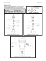
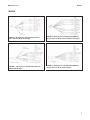
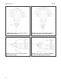
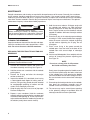
1
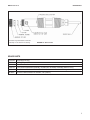
Instruction Sheet
PN 51A-499ACL01/rev.K
September 2010
Model 499A CL-01
Free Chlorine Sensor
For additional information, please visit our website
at www.emersonprocess.com/raihome/liquid/.
CAUTION
SENSOR/PROCESS APPLICATION COMPATIBILITY
The wetted sensor materials may not be compatible
with process composition and operating conditions.
Application compatibility is entirely the responsibility of
the user.
CAUTION
Do not exceed pressure and temperature specifications.
Pressure: 65 psig max (549 kPa abs max)
Temperature: 32 to 122°F (0 to 50°C)
SPECIFICATIONS - SENSOR
Pressure: 0 to 65 psig (0 to 549 kPa abs)
Temperature: 32 to 122°F (0 to 50°C)
Process Connection: 1 inch MNPT
Wetted Parts: Noryl®1, Viton®2, platinum, polyethersulfone,
polyester, wood, silicone
1 Noryl is a registered trademark of General Electric.
2 Viton is a registered trademark of DuPont Performance Elastomers
SPECIFICATIONS - FLOW CELLS
Type
1-1/2 in. tee
2 in. tee
Low Flow*
PN
23567-00
915240-03
915240-04
915240-05
24091-00
Wetted Materials
CPVC, Buna N
Process Connection Max.Temperature
1-1/2 in. socket
122°F (50°C)
3/4 in. NFPT
PVC, Buna N
1 in. NFPT
120°F (49°C)
1-1/2 in. NFPT
Polycarbonate/
Compression fitting for
158°F (70°C)
polyester, 316SS,
1/4 in. OD tubing
silicone
24091-01 (with Polycarbonate/
Compression fitting for
158°F (70°C)
bubble sweep- polyester, 316SS,
1/4 in. OD tubing
ing nozzle)
silicone
Max. Pressure
65 psig (549 kPa abs)
60 psig (515 kPa abs)
90 psig (722 kPa abs)
90 psig (722 kPa abs)
* Pressure and temperature specifications for the low flow cell exceed the temperature and pressure specifications for the sensor.
MODEL 499A CL-01
INSTALLATION
INSTALLATION
Install the sensor in a flowing sample. Keep the sample flow
as constant as possible at a value within the limits below.
Flow through
Open channel
Low flow cell (PN 24091-00)
Low flow cell (PN 24091-01)
1
1
8
2
to 5 gpm (3.8 to 19 L/min)
ft/sec (0.3 m/sec)
to 15 gph (30 to 57 L/hr)
to 3 gph (120 to 190 mL/min)
FIGURE 2. Flow-Through 1-1/2 in. Tee
FIGURE 1. Sensor Orientation
FIGURE 3. Flow-Through 2 in. Tee
PN 24091-01 has
bubble sweeping
nozzle for low flow
applications (2 to
3 gph).
FIGURE 4. Low Flow Cell (PN 24091-00 or 24091-01)
2
MODEL 499A CL-01
WIRING
WIRING
FIGURE 5. Wiring Sensor with Standard Cable to
Model 1056 and Model 56 Analyzer
FIGURE 7. Wiring Sensor with Standard Cable to
Model 54eA Analyzer
FIGURE 6. Wiring Sensor with Optimum EMI/RFI or
Variopol Cable to Model 1056 and Model 56 Analyzer
FIGURE 8. Wiring Sensor with Optimum EMI/RFI or
Variopol Cable to Model 54eA Analyzer
3
MODEL 499A CL-01
FIGURE 9. Wiring Sensor with Standard Cable to
Model 5081-A Transmitter.
FIGURE 11. Wiring Sensor with Standard Cable to
Model Xmt-A Transmitter.
4
WIRING
FIGURE 10. Wiring Sensor with Optimum EMI/RFI or
Variopol Cable to Model 5081-A Transmitter.
FIGURE 12. Wiring Sensor with Optimum EMI/RFI or
Variopol Cable to Model Xmt-A Transmitter.
MODEL 499A CL-01
FIGURE 13. Wiring Sensor with Standard Cable to
Model 1066 Transmitter.
WIRING
FIGURE 14. Wiring Sensor with Optimum EMI/RFI or
Variopol Cable to Model 1066 Transmitter.
When making connections through a junction box
(PN 23550-00), wire point-to-point.
NOTE:
Use a wire nut and pigtail (included) when
connecting several wires to the same terminal.
FIGURE 15. Pin Out Diagram for Model 499ACLVP Sensor (top view of connector end of sensor)
CALIBRATION
Zero point: Even in the absence of free chlorine, the
499ACL-01 sensor generates a small signal called the
zero current. Failing to correct for the zero current can
introduce a bias, particularly if the chlorine concentration is small (<0.4 ppm). Zero the sensor when it is first
placed in service and every time the fill solution is
changed. To zero the sensor, place it in a cup of deionized or bottled water to which a few pinches of table
salt have been added to increase the conductivity.
Once the sensor current has reached a stable low
value, which takes at least two hours, follow the analyzer prompts for zeroing the sensor. The zero current
should between -10 and +10 nA. For more information
refer to the analyzer manual.
Full Scale: Because stable dilute chlorine standards
are not available, the sensor must be calibrated
against the results of a laboratory test run on a grab
sample of the process liquid. Place the sensor in the
flow cell and adjust the sample flow to within the range
given in the table on page 2. Also, adjust the concentration so that it is near the upper end of the operating
range. Once readings are stable, follow the analyzer
prompts to complete the calibration. Be sure taking the
sample does not alter flow to the sensor and test the
sample immediately after taking it. After calibration, go
to the diagnostics menu and check the sensitivity. It
should be between 200 and 450 nA/ppm. For more
information, refer to the analyzer manual.
5
MODEL 499A CL-01
MAINTENANCE
MAINTENANCE
Periodic maintenance and cleaning are required for best performance of the sensor. Generally, the membrane
and fill solution should be replaced every one to three months. If the sensor is being used in water having
conductivity less than about 100 µS/cm, it might be necessary to replace the fill solution (but not the membrane)
more often. Sensors installed in harsh or dirty environments require more frequent maintenance. The optimum
maintenance frequency is best determined by experience.
CAUTION
PRESSURIZED SPRAY INJURY
Before removing the sensor, be absolutely certain
that the process pressure is reduced to 0 psig and
the process temperature is lowered to a safe level!
CLEANING THE MEMBRANE.
Keep the membrane clean and free from dirt and algae.
Clean the membrane with water sprayed from a wash
bottle. Do not use tissues to clean the membrane.
REPLACING THE ELECTROLYTE SOLUTION AND
MEMBRANE.
CAUTION
Fill solution may cause irritation. May be harmful if
swallowed. Read and follow manual.
1. Unscrew the membrane retainer and remove the
membrane assembly and O-ring. See Figure 16.
2. Hold the sensor over a container with the cathode
pointing down.
3. Remove the fill plug and allow the electrolyte
solution to drain out.
4. Inspect the cathode. If it is tarnished, clean it using
a cotton-tipped swab dipped in baking soda or
alumina. Use type A dry powder alumina intended
for metallographic polishing of medium and soft
metals. Rinse thoroughly with water.
5. Wrap the plug with one or two turns of pipe tape.
Remove old tape first.
6. Prepare a new membrane. Hold the membrane
assembly with the cup formed by the membrane and
membrane holder pointing up. Fill the cup with electrolyte solution and allow the wooden ring to soak up
the solution (usually takes several minutes).
6
7. Hold the sensor at about a 45-degree angle with
the cathode end pointing up. Add electrolyte
solution through the fill hole until the liquid overflows. Tap the sensor near the threads to release
trapped air bubbles. Add more electrolyte solution
if necessary.
8. Place the fill plug in the electrolyte port and begin
screwing it in. After several threads have engaged,
rotate the sensor so that the cathode is pointing
up and continue tightening the fill plug. Do not
overtighten.
9. Place a new O-ring in the groove around the
cathode post. Cover the holes at the base of the
cathode stem with several drops of electrolyte
solution.
10. Insert a small blunt probe, like a toothpick with the
end cut off, through the pressure equalizing port.
See Figure 16.
NOTE
Do not use a sharp probe. It will puncture
the bladder and destroy the sensor.
Gently press the probe against the bladder several
times to force liquid through the holes at the base
of the cathode stem. Keep pressing the bladder
until no air bubbles can be seen leaving the holes.
Be sure the holes remain covered with electrolyte
solution.
11. Place a drop of electrolyte solution on the cathode,
then place the membrane assembly over the
cathode. Screw the membrane retainer in place.
12. The sensor may require several hours operating
at the polarizing voltage to equilibrate after the
electrolyte solution has been replenished.
MODEL 499A CL-01
A wooden ring rests inside the membrane
assembly. It is not shown in the drawing.
MAINTENANCE
FIGURE 16. Sensor Parts
SPARE PARTS
33523-00
Electrolyte Fill Plug
9550094
O-Ring, Viton 2-014
33521-00
Membrane Retainer
23501-08
Free Chlorine Membrane Assembly: includes one membrane assembly and one O-ring
23502-08
Free Chlorine Membrane Kit: includes 3 membrane assemblies and 3 O-rings
9210356
#4 Free Chlorine Sensor Fill Solution, 4 oz (120 mL)
7
The right people,
the right answers,
right now.
ON-LINE ORDERING NOW AVAILABLE ON OUR WEB SITE
http://www.raihome.com
Specifications subject to change without notice.
8
Credit Cards for U.S. Purchases Only.
Emerson Process Management
2400 Barranca Parkway
Irvine, CA 92606 USA
Tel: (949) 757-8500
Fax: (949) 474-7250
http://www.raihome.com
© Rosemount Analytical Inc. 2010