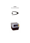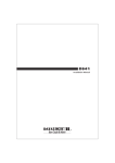
1
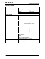
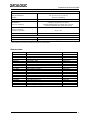
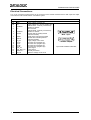
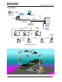
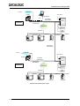
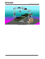
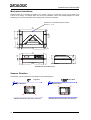
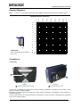
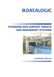
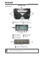
DX8200A-3002 QUICK GUIDE
DX8200A-3002
General View:
1
2
2
3
4
Figure A
1 Laser Beam Output Windows
3 Laser Safety Label
2 Mounting Slots
4 Mounting Reference Label
7
1
2
4
3
5
6
Figure B
1 Programming Keypad
5 TX Data LED (Green)
2 Power On LED (Green)
6 Network LED (Red)
3 Phase On LED (Yellow)
7 LCD Display
4 Encoder LED (Yellow)
1
2
Figure C
1 Lonworks 17-pin Male Connector
2 Lonworks 17-pin Female Connector
For further details on product installation, see the complete Reference Manual available on the
configuration CD-ROM included with this product.
NOTE
DX8200A-3002 QUICK GUIDE
Technical Features:
ELECTRICAL FEATURES
Supply voltage
Power consumption
Communication Interfaces
Auxiliary
RS232
Other
Lonworks
20 to 30 Vdc
30 W typical
35 W Max. (including startup current)
Baud Rate
1200 to 115200
1.25 Mb/s
OPTICAL FEATURES
Light receiver
Wavelength
Safety class
Light source
Laser control
Avalanche photodiode
630 to 680 nm
Class 2 - EN60825-1; Class II - CDRH
Up to 4 semiconductor laser diodes
Security system to turn laser off in case of motor slow down
READING FEATURES
Scan rate
Maximum resolution
Max. reading distance
Max. reading width
Max. depth of field
≤ 1000 scans/s (500 per leg)
(see reading diagrams on page 9)
USER INTERFACE
LCD Display
Keypad
LED indicators
2 lines by 20 characters LCD
3 keys
Power On (green)
Phase On (yellow)
Encoder (yellow)
TX Data (green)
Network (red)
SOFTWARE FEATURES
Readable Codes
Code selection
Operating modes
Configuration modes
Parameter storage
2
Interleaved 2/5
Code 39 Standard
Codabar
Code 128
EAN 128
Code 93 (standard and full ASCII)
EAN/UPC (including Add-on 2 and Add-on 5)
Up to 10 codes during one reading phase
PackTrack™
Genius™ utility program
Non-volatile internal FLASH
DX8200A-3002 QUICK GUIDE
ENVIRONMENTAL FEATURES
Operating temperature
Storage temperature
Humidity
Ambient light immunity
Vibration resistance:
EN 60068-2-6
2 hours on each axis
0° to +50 °C (+32° to +122 °F)
-20° to +70 °C (-4° to +158 °F)
90% non condensing
20000 lux
Frequency range from 5 to 150 Hz;
Constant displacement 3 mm pk-pk from 5 to 9 Hz;
Constant acceleration 0.5 g from 9 to 150 Hz;
Shock resistance:
IEC 68-2-27 test EA
3 shocks on each axis
30 g; 11 ms
Protection Class
IP65*
PHYSICAL FEATURES
Mechanical dimensions
Weight
470 x 300 x 141 mm (18.50 x 11.81 x 5.55 in)
about 11 kg (24 lbs 3 oz)
* IP65 cables and connectors required (CAB-850x or BTK-8500).
Accessories:
NAME
PWO-480
FS-1
S30
MEP-542
MEP-543
OEK-2
OEK-1
BTK-8100
BTK-8500
PLL-8000
CAB-8100
CAB-8101
CAB-8102
CAB-8105
CAB-8501
CAB-8502
CAB-8505
Sentinel-5
Sentinel-10
Sentinel-32
Description
Power and Connect System 480W
Frame Shaper (8 pcs)
Photocell Kit
Photocell Kit - PNP
Photocell Kit - NPN
Optical Encoder Kit + 10 m cable + Spring
Optical Encoder Kit + 10 m cable
Bus Terminator Kit (5 pcs)
IP65 Terminator Kit (2 pcs)
Optocoupled PLL device
10 wire shielded cable D 9.5 mm – 50 m
17-pin scanner/scanner connection cable 1.2 m
17-pin scanner/scanner connection cable 2.5 m
17-pin scanner/scanner connection cable 5 m
IP65 Cable Fam 8K 1,2 m
IP65 Cable Fam 8K 2,5 m
IP65 Cable Fam 8K 5 m
Supervisor (up to 5 arrays)
Supervisor (up to 10 arrays)
Supervisor (up to 32 arrays)
Part Number
93ACC1767
93ACC1750
93ACC1782
93ACC1727
93ACC1728
93ACC1770
93ACC1600
93ACC1090
93A051286
93ACC1280
93ACC1120
93A051020
93A051030
93A051040
93A051283
93A051284
93A051285
93A101004
93A101005
93A101007
3
DX8200A-3002 QUICK GUIDE
Electrical Connections:
Two 17-pin connectors provide access to the scanner’s local Lonworks network used for both input and output
connections to build a multi-sided or omni-station system.
17-pin Lonworks Connector Pinout
Pin
A1
A2
4
Name
GND
VS
1
CHASSIS
2
n.c.
3
CHASSIS
4
TXAUX
5
SGND
6
RXAUX
7
8
9
10
11
12
13
14
15
VS_I/O
Lon A+
Lon ALon B+
Lon BSYS_I/O
SYS_ENC_I/O
Reserved
Ref_I/O
Function
Supply voltage (negative pin)
Supply voltage 20 to 30 Vdc (positive pin)
Cable shield A - internally connected by
capacitor to chassis
Not connected
Cable shield B - internally connected by
capacitor to chassis
Transmit data of auxiliary RS232
(referred to SGND)
Signal ground (connected to GND)
Receive data of auxiliary RS232
(referred to SGND)
Supply voltage of I/O circuit
Lonworks a line (positive pin)
Lonworks a line (negative pin)
Lonworks b line (positive pin)
Lonworks b line (negative pin)
System signal
System signal
Internally connected
Reference voltage of I/O circuit
1
A1
A2
15
Male - Input
15
A1
1
A2
Female - Output
17-pin Local Lonworks Connectors
DX8200A-3002 QUICK GUIDE
Connectivity:
Host
HUB
ETHERNET
CAB-SC6103
Cable
SC6000
AUX
VAC INPUT
Power/Net
CAB-SC6003
PWO
CAB-SC6003
Extended I/O
LONWORKS
ENCODER
BTK8500
Bus Return
CAB-850x
CAB-850x
CAB-850x
PS
PS Aux
CAB-850x
up to 3
scanners
per
branch
DX8200A-3002
DX8200A-3002
CAB-850x
CAB-850x
BTK8500
Bus Return
DX8200A-3002
CAB-850x
up to 4
scanners per
branch
DS8100A-3002
DS8100A-3002
DS8100A-3002
DS8100A-3002
DX8200A-3002 Typical Layout
5
DX8200A-3002 QUICK GUIDE
to Host
ETHERNET
SC6000
CAB-SC6103
AUX
Working
Controller
VAC INPUT
Power/Net
CAB-SC6003
PWO
CAB-SC6003
Extended I/O
LONWORKS
ENCODER
CAB-850x
CAB-850X
CAB-850x
DX8200A
PS
PS Aux
DS8100A
DS8100A
DX8200A
BTK8500
CAB-850x
Redundancy
CAB-PWO 03
ETHERNET
to Host
VAC INPUT
SC6000
Power/Net
CAB-SC6003
PWO
CAB-SC6003
Extended I/O
Protecting
Controller
LONWORKS
ENCODER
CAB-850x
CAB-850X
CAB-850x
DX8200A
PS
PS Aux
DX8200A
CAB-850x
DS8100A
Example of Redundant System Layout
6
BTK8500
DS8100A
DX8200A-3002 QUICK GUIDE
Example of Redundant System
7
DX8200A-3002 QUICK GUIDE
Mechanical Installation:
DX8200A-3002 can be installed to operate in any position. There are 4 slots (dia. 8.5 mm) on the sides of the
scanner for mounting. The diagram below can be used for installation; refer to the Reading Diagrams for correct
positioning of the scanner with respect to the reading zone and scanner orientation.
PackTrack™ Coordinate Reference Point
where x, y, z = 0
470
[18.50]
=
8.5 N° 4
[0.33]
180
[7.09]
=
300
[11.81]
=
=
22
[0.87]
406
[15.98]
22
[0.87]
370
[14.57]
=
=
370
[14.57]
=
141
[5.55]
70.5
[2.78]
147
[5.79]
60.5
[2.38]
10
[0.39]
=
DX8200A-3002 Overall Dimensions
Scanner Direction
The different scanner orientations are illustrated in the following figures:
Top View
Conveyor Direction
DX8200A-3002 Scanner Direction 0° (Forward)
8
Top View
Conveyor Direction
DX8200A-3002 Scanner Direction 180° (Reverse)
DX8200A-3002 QUICK GUIDE
Reading Diagrams:
Note:
x = 0 and z = 0 correspond to the edge of the DX8200A-3002 scanner as shown in the figure below.
DX8200A-3002 (0.50 mm/20 mils)
-28
-70
-24
-60
-20
-50
-16
-40
-12
-30
-8
-20
-4
-10
z
x
CONDITIONS
Code = Interleaved 2/5 or Code 39
PCS = 0.90
0
0
4
10
8
20
12
30
16
40
20
50
24
60
0
-15
0
-40
-24
-60
-32
-40
-48
-56
-64
-80
-100
-120
-140
-160
(in)
(cm)
70
28
(in) (cm)
Compliance:
Laser Safety
1
1
Figure A
1 Warning and Device Class Label
Figure B
1 Device Identification Label
The scanner is classified as a Class 2 laser product according to EN60825-1 regulations and as a Class II laser
product according to CDRH regulations.
Disconnect the power supply when opening the device during maintenance or installation to avoid exposure to
hazardous laser light.
There is a safety device, which allows the laser to be switched on only if the motor is rotating above the threshold
for its correct scanning speed.
9
DX8200A-3002 QUICK GUIDE
The laser beam can be switched off through a software command (see also the Genius™ Help On-Line).
LASER LIGHT
DO NOT STARE INTO BEAM
CLASS 2 LASER PRODUCT
MAXIMUM OUTPUT RADIATION 1 mW
EMITTED WAVELENGTH 630~680 nm
TO EN 60825-1:2001
DATALOGIC S.P.A. Via Candini, 2
40012 Calderara di Reno - Bologna - Italy
CAUTION-CLASS 3B LASER LIGHT WHEN OPEN
AVOID EXPOSURE TO BEAM
Manufactured
Volt
Model No.
Amp.
Serial No.
This product conforms to the applicable requirements
of 21CFR1040 at the date of manufacture.
LASER LIGHT EMITTED
FROM THIS
APERTURE
Device Identification Label
Warning and Device Class Label
The laser diodes used in this device are classified as Class 3B laser products according to EN 60825-1 regulations
and as Class IIIb laser products according to CDRH regulations. As it is not possible to apply a classification label
on the laser diodes used in this device, the following label is reproduced here:
LASER LIGHT
AVOID EXPOSURE TO BEAM
CLASS 3B LASER PRODUCT
MAXIMUM OUTPUT RADIATION 30 mW
EMITTED WAVELENGTH 630~680 nm
TO EN 60825-1 (2001)
Laser Diode Class Label
Any violation of the optic parts in particular can cause radiation up to the maximum level of the laser diode
(30 mW at 630~680 nm).
Power Supply
This product is intended to be installed by Qualified Personnel only.
This scanner is intended to be supplied by either a UL Listed power supply marked 'Class 2' or 'LPS', output
rated 20 - 30 V dc, minimum 1.75 A or by a UL Listed computer with LPS outputs.
This scanner must be supplied by a Class II Power Supply Unit conforming to the EN 60950 safety
regulation.
WEEE Compliance
10
DATALOGIC S.p.A.,
Via Candini, 2
40012 - Lippo di Calderara
Bologna - Italy
05
dichiara che
declares that the
déclare que le
bescheinigt, daß das Gerät
declare que el
DX8200A-XXXX, Laser Scanner
e tutti i suoi modelli
and all its models
et tous ses modèles
und seine Modelle
y todos sus modelos
sono conformi alle Direttive del Consiglio Europeo sottoelencate:
are in conformity with the requirements of the European Council Directives listed below:
sont conformes aux spécifications des Directives de l'Union Européenne ci-dessous:
den nachstehenden angeführten Direktiven des Europäischen Rats:
cumple con los requisitos de las Directivas del Consejo Europeo, según la lista siguiente:
89/336/EEC EMC Directive
e
and
et
und
y
92/31/EEC, 93/68/EEC
emendamenti successivi
further amendments
ses successifs amendements
späteren Abänderungen
succesivas enmiendas
73/23/EEC Low Voltage Directive
Basate sulle legislazioni degli Stati membri in relazione alla compatibilità elettromagnetica ed alla sicurezza dei prodotti.
On the approximation of the laws of Member States relating to electromagnetic compatibility and product safety.
Basée sur la législation des Etats membres relative à la compatibilité électromagnétique et à la sécurité des produits.
Über die Annäherung der Gesetze der Mitgliedsstaaten in bezug auf elektromagnetische Verträglichkeit und Produktsicherheit
entsprechen.
Basado en la aproximación de las leyes de los Países Miembros respecto a la compatibilidad electromagnética y las Medidas
de seguridad relativas al producto.
Questa dichiarazione è basata sulla conformità dei prodotti alle norme seguenti:
This declaration is based upon compliance of the products to the following standards:
Cette déclaration repose sur la conformité des produits aux normes suivantes:
Diese Erklärung basiert darauf, daß das Produkt den folgenden Normen entspricht:
Esta declaración se basa en el cumplimiento de los productos con las siguientes normas:
LIMITS AND METHODS OF MEASUREMENTS OF RADIO DISTURBANCE
EN 55022 (CLASS A ITE),: AUGUST 1994
AMENDMENT A1 (CLASS A ITE), OCTOBER 2000: CHARACTERISTICS OF INFORMATION TECHNOLOGY EQUIPMENTS
EN 61000-6-2, OCTOBER 2001:
ELECTROMAGNETIC COMPATIBILITY (EMC).
PART 6-2: GENERIC STANDARDS - IMMUNITY FOR INDUSTRIAL ENVIRONMENTS
EN 60950-1, DECEMBER 2001:
INFORMATION TECHNOLOGY EQUIPMENT - SAFETY –
PART 1: GENERAL REQUIREMENTS
EN 60825-1, JUNE 1994:
AMENDMENTS A11 (1996), A2 (2001)
SAFETY OF LASER PRODUCTS –
PART 1: EQUIPMENT CLASSIFICATION, REQUIREMENTS AND USER’S GUIDE
EN 61000-3-2, DECEMBER 2000:
ELECTROMAGNETIC COMPATIBILITY (EMC)
PART 3-2: LIMITS FOR HARMONIC CURRENT EMISSIONS (EQUIPMENT INPUT
CURRENT UP TO AND INCLUDING 16A PER PHASE)
EN 61000-3-3, JULY 1995:
ELECTROMAGNETIC COMPATIBILITY (EMC)
PART 3: LIMITS SECTION 3: LIMITATION OF VOLTAGE FLUCTUATIONS AND FLICKER IN
LOW-VOLTAGE SUPPLY SYSTEMS FOR EQUIPMENT WITH RATED CURRENT <= 16A
PART 1: EQUIPMENT CLASSIFICATION, REQUIREMENTS AND USER'S GUIDE
Lippo di Calderara, 08/09/2005
Ruggero Cacioppo
Quality Assurance Laboratory Manager
821001251 (Rev. A)