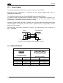
1
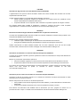
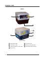
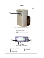
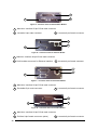
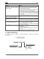
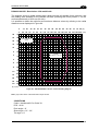
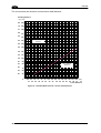
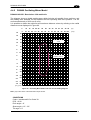
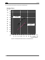
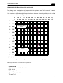
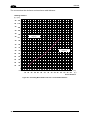
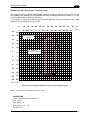
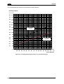
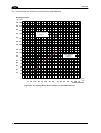
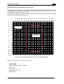
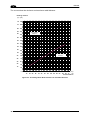
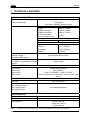
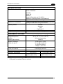
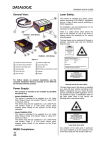
DS6400
Reference Manual
Datalogic Automation S.r.l.
Via S. Vitalino 13
40012 - Lippo di Calderara di Reno
Bologna - Italy
DS6400 Reference Manual
Ed.: 10/2007
ALL RIGHTS RESERVED
Datalogic reserves the right to make modifications or improvements without prior notification.
Datalogic shall not be liable for technical or editorial errors or omissions contained herein, nor for
incidental or consequential damages resulting from the use of this material.
Product names mentioned herein are for identification purposes only and may be trademarks and or
registered trademarks of their respective companies.
© Datalogic Automation S.r.l. 2003 - 2007
03/10/2007
CONTENTS
REFERENCES ............................................................................................................ vi
Reference Documentation ........................................................................................... vi
Services and Support .................................................................................................. vi
Patents......................................................................................................................... vi
COMPLIANCE............................................................................................................ vii
Electrical Safety ...........................................................................................................vii
Laser Safety.................................................................................................................vii
Power Supply..............................................................................................................viii
CE Compliance...........................................................................................................viii
WEEE Compliance .....................................................................................................viii
GENERAL VIEW .......................................................................................................... x
GUIDE TO INSTALLATION ...................................................................................... xiii
Point-to-Point Installation............................................................................................xiii
Master/Slave Lonworks Installation ............................................................................xiv
1
1.1
1.2
1.3
1.4
1.5
INTRODUCTION .......................................................................................................... 1
Product Description ...................................................................................................... 1
Model Description ......................................................................................................... 2
Oscillating Mirror Models .............................................................................................. 3
Indicators ...................................................................................................................... 5
Accessories .................................................................................................................. 6
2
2.1
2.2
2.2.1
2.2.2
2.3
2.3.1
INSTALLATION ........................................................................................................... 7
Package Contents ........................................................................................................ 7
Mechanical Mounting.................................................................................................... 8
Mounting the Scanner................................................................................................... 8
Mounting the Scanner with Accessories..................................................................... 11
Electrical Connections ................................................................................................ 13
Main/Aux. Serial Interface and I/O Connector ............................................................ 15
Main Interface ............................................................................................................. 16
Auxiliary Interface ....................................................................................................... 19
Inputs .......................................................................................................................... 20
Outputs ....................................................................................................................... 22
Lonworks Connectors ................................................................................................. 24
Network Termination................................................................................................... 25
Lonworks Interface ..................................................................................................... 26
Ethernet Connector..................................................................................................... 28
Ethernet Interface ....................................................................................................... 29
DeviceNet Connector.................................................................................................. 30
Profibus Connector ..................................................................................................... 31
Profibus Interface........................................................................................................ 31
Power Supply.............................................................................................................. 32
User Interface ............................................................................................................. 32
Positioning the Scanner.............................................................................................. 33
Typical Installations .................................................................................................... 35
Standard Installation ................................................................................................... 35
“45° Skew” Installation ................................................................................................ 35
Typical Layouts........................................................................................................... 36
2.3.2
2.3.3
2.3.4
2.3.5
2.3.6
2.4
2.5
2.6
2.6.1
2.6.2
2.7
iii
2.7.1
2.7.2
2.7.3
2.7.4
2.7.5
2.7.6
2.8
2.8.1
2.8.2
2.8.3
2.8.4
2.9
2.9.1
2.9.2
3
3.1
3.2
3.2.1
Point-to-Point .............................................................................................................. 36
Pass Through ............................................................................................................. 38
RS232 Master/Slave................................................................................................... 39
Multiplexer .................................................................................................................. 41
Local Lonworks Network............................................................................................. 42
Small Synchronized Network...................................................................................... 43
Large Synchronized Network...................................................................................... 45
Multidata Network ....................................................................................................... 46
Fieldbus Network ........................................................................................................ 47
FLASH™ Dynamic Focus........................................................................................... 48
Fixed Mode ................................................................................................................. 48
Continuous Mode........................................................................................................ 48
Triggered Mode .......................................................................................................... 49
D-FLASH™ Mode....................................................................................................... 49
Keypad and Display.................................................................................................... 50
Internal Net ................................................................................................................. 50
Test Mode................................................................................................................... 51
3.2.3
3.3
3.4
SOFTWARE CONFIGURATION................................................................................ 52
Genius™ Installation................................................................................................... 52
Guide to Rapid Configuration ..................................................................................... 52
Wizard for Quick Reader Setup .................................................................................. 52
Test Operating Mode .................................................................................................. 53
On Line Operating Mode ............................................................................................ 54
Automatic Operating Mode ......................................................................................... 54
Genius™ Network Setup Through Master.................................................................. 55
Net-Autoset................................................................................................................. 57
Express Network Setup .............................................................................................. 57
Network Wizard .......................................................................................................... 58
Alternative Slave Address Assignment....................................................................... 60
Advanced Genius™ Configuration ............................................................................. 60
Parameter Default Values........................................................................................... 61
4
4.1
4.1.1
4.2
4.2.1
4.2.2
4.3
4.3.1
4.4
4.4.1
4.4.2
READING FEATURES............................................................................................... 65
Advanced Code Reconstruction (ACR™ 4)................................................................ 65
Tilt Angle for Advanced Code Reconstruction ............................................................ 65
PackTrack™ ............................................................................................................... 66
PackTrack™ Calibration for DS6400.......................................................................... 68
PackTrack™ Calibration for DS6400 Oscillating Mirror Models ................................. 70
Performance ............................................................................................................... 70
Reading Conditions .................................................................................................... 70
Reading Diagrams ...................................................................................................... 72
DS6400 Standard Model ............................................................................................ 73
DS6400 Oscillating Mirror Model ................................................................................ 83
5
5.1
5.2
5.2.1
5.2.2
MAINTENANCE ......................................................................................................... 93
Cleaning...................................................................................................................... 93
Automatic Scanner Replacement (ASR) .................................................................... 93
ASR Network Configuration........................................................................................ 93
Scanner Replacement Procedure............................................................................... 94
6
TROUBLESHOOTING ............................................................................................... 95
7
TECHNICAL FEATURES........................................................................................... 98
3.2.2
iv
GLOSSARY.............................................................................................................. 100
INDEX....................................................................................................................... 103
v
REFERENCES
REFERENCE DOCUMENTATION
The documentation related to the DS6400 management is listed below:
•
C-BOX100 Installation Manual
•
INT-30 20 mA Current Loop Interface Board for C-BOX 100
•
PWR-120 power supply unit
•
GFC-60 90° deflecting mirror
•
GFC-600 90° deg. mirror close distance
•
Document about the Ethernet connectivity
•
Document about the Profibus connectivity
•
Help On-Line in PDF format
SERVICES AND SUPPORT
Datalogic provides several services as well as technical support through its website. Log on
to www.automation.datalogic.com and click on the links indicated for further information
including:
•
PRODUCTS
Search through the links to arrive at your product page where you can download specific
Manuals and Software & Utilities including:
- Genius™ a utility program, which allows device configuration using a PC. It provides
RS232 interface configuration.
•
SERVICES & SUPPORT
- Datalogic Services - Warranty Extensions and Maintenance Agreements
- Authorised Repair Centres
•
CONTACT US
E-mail form and listing of Datalogic Subsidiaries
PATENTS
This product is covered by one or more of the following patents:
U.S. patents: 5,483,051; Re. 36,251; 6,049,406; 5,992,740; 6,347,740B1; 6,629,639B2;
6,394,352B1; 6,742,710B2; 7,161,685B1; 6,688,524B1; 6,443,360 B1; 7,195,162B2.
European patents: 652,530B1;
959,426B9; 1,300,798B1.
Additional patents pending.
vi
786,734B1;
789,315B1;
851,376B1;
1,363,228B1;
COMPLIANCE
ELECTRICAL SAFETY
This product conforms to the applicable requirements contained in the European Standard for
electrical safety EN-60950-1 at the date of manufacture.
LASER SAFETY
The following information is provided to comply with the rules imposed by international
authorities and refers to the correct use of the DS6400 reader.
Standard Regulations
This scanner utilizes a low-power laser diode. Although staring directly at the laser beam
momentarily causes no known biological damage, avoid staring at the beam as one would
with any very strong light source, such as the sun.
Avoid that the laser beam hits the eye of an observer, even through reflective surfaces such
as mirrors, etc.
This product conforms to the applicable requirements of both EN60825-1 and
CDRH 21 CFR1040 at the date of manufacture. The reader is classified as a Class 2 laser
product according to EN60825-1 regulations and as a Class II laser product according to
CDRH regulations.
Disconnect the power supply when opening the device during maintenance or installation to
avoid exposure to hazardous laser light.
There is a safety device which allows the laser to be switched on only if the motor is rotating
above the threshold for its correct scanning speed.
Use of controls or adjustments or performance of procedures other than those
specified herein may result in exposure to hazardous visible laser light.
WARNING
The laser light is visible to the human eye and is emitted from the window on the head of the
reader (Figure A, 7).
Warning labels indicating exposure to laser light and the device classification are applied
onto the head of the reader (Figure A, 1, 3):
AVOID EXPOSURE
LASER RADIATION IS EMITTED FROM THIS APERTURE
AVOID EXPOSURE – LASER LIGHT
IS EMITTED FROM THIS APERTURE
Laser Safety Label for Oscillating Mirror and Standard Models
CAUTION-CLASS 3B
LASER LIGHT
WHEN OPEN
AVOID EXPOSURE
TO BEAM
LASER LIGHT – DO NOT STARE INTO BEAM
CLASS 2 LASER PRODUCT
MAX. OUTPUT RADIATION 1 mW
EMITTED WAVE LENGTH 630 ~ 680 nm
EN60825-1:2001
Warning and Device Class Label
vii
The identification label is applied onto the bottom part of the scanner (Figure A, 2):
DATALOGIC S.p.A. Via Candini, 2
40012 LIPPO DI CALDERARA DI RENO (BO) ITALY
MANUFACTURED VOLT
Amp.
JANUARY 2002
15-30 DC 1.5-0.7
MODEL No.
N2468
SERIAL No.
This product conforms to the applicable requirements
of 21CFR 1040 at the date of manufacture.
Device Identification Label
The laser diode used in this device is classified as a Class 3B laser product according to
EN60825-1 regulations and as a Class IIIb laser product according to CDRH regulations. Any
violation of the optic parts in particular can cause radiation up to the maximum level of the
laser diode (35 mW at 630~680 nm).
POWER SUPPLY
-
This product is intended to be installed by Qualified Personnel only.
-
All DS6400 Models:
This device is intended to be supplied by a UL Listed Power Unit marked “Class 2” or LPS
power source which supplies power directly to the scanner via the 25/26-pin connector.
CE COMPLIANCE
Warning:
This is a Class A product. In a domestic environment this product may cause radio
interference in which case the user may be required to take adequate measures.
WEEE COMPLIANCE
ENGLISH
Information for the user in accordance with the European Commission Directive 2002/96/EC
At the end of its useful life, the product marked with the crossed out wheeled wastebin must be disposed of
separately from urban waste.
Disposing of the product according to this Directive:
•
avoids potentially negative consequences to the environment and human health which otherwise could
be caused by incorrect disposal
•
enables the recovery of materials to obtain a significant savings of energy and resources.
For more detailed information about disposal, contact the supplier that provided you with the product in question
or consult the dedicated section at the website www.automation.datalogic.com.
viii
ITALIANO
Informazione degli utenti ai sensi della Direttiva Europea 2002/96/EC
L’apparecchiatura che riporta il simbolo del bidone barrato deve essere smaltita, alla fine della sua vita utile,
separatamente dai rifiuti urbani.
Smaltire l’apparecchiatura in conformità alla presente Direttiva consente di:
•
evitare possibili conseguenze negative per l’ambiente e per la salute umana che potrebbero invece
essere causati dall’errato smaltimento dello stesso;
•
recuperare materiali di cui è composto al fine di ottenere un importante risparmio di energia e di risorse.
Per maggiori dettagli sulle modalità di smaltimento, contattare il Fornitore dal quale è stata acquistata
l’apparecchiatura o consultare la sezione dedicata sul sito www.automation.datalogic.com.
DEUTSCH
Benutzerinformation bezüglich Richtlinie 2002/96/EC der europäischen Kommission
Am Ende des Gerätelebenszyklus darf das Produkt nicht über den städtischen Hausmüll entsorgt werden. Eine
entsprechende Mülltrennung ist erforderlich.
Beseitigung des Produkts entsprechend der Richtlinie:
•
verhindert negative Auswirkungen für die Umwelt und die Gesundheit der Menschen
•
ermöglicht die Wiederverwendung der Materialien und spart somit Energie und Resourcen
Weitere Informationen zu dieser Richtlinie erhalten Sie von Ihrem Lieferanten, über den Sie das Produkt
erworben haben, oder besuchen Sie unsere Homepage unter www.automation.datalogic.com.
FRANÇAIS
Information aux utilisateurs concernant la Directive Européenne 2002/96/EC
Au terme de sa vie utile, le produit qui porte le symbole d'un caisson à ordures barré ne doit pas être éliminé avec
les déchets urbains.
Éliminer ce produit selon cette Directive permet de:
•
éviter les retombées négatives pour l'environnement et la santé dérivant d'une élimination incorrecte
•
récupérer les matériaux dans le but d'une économie importante en termes d'énergie et de ressources
Pour obtenir des informations complémentaires concernant l'élimination, veuillez contacter le fournisseur auprès
duquel vous avez acheté le produit ou consulter la section consacrée au site Web
www.automation.datalogic.com.
ESPAÑOL
Información para el usuario de accuerdo con la Directiva Europea 2002/96/CE
Al final de su vida útil, el producto marcado con un simbolo de contenedor de bassura móvil tachado no debe
eliminarse junto a los desechos urbanos.
Eliminar este producto de accuerdo con la Directiva permite de:
•
evitar posibles consecuencias negativas para el medio ambiente y la salud derivadas de una eliminación
inadecuada
•
recuperar los materiales obteniendo así un ahorro importante de energía y recursos
Para obtener una información más detallada sobre la eliminación, por favor, póngase en contacto con el
proveedor donde lo compró o consultar la sección dedicada en el Web site www.automation.datalogic.com.
ix
GENERAL VIEW
DS6400
1
7
2
3
4
6
5
Figure A - DS6400
x
1
Laser Safety Label
5
Connector Panel
2
Identification Label
6
Display and Keypad Panel
3
Warning and Device Class Label
7
Laser Beam Output Window
4
Service Cap
DS6400
1
2
Figure B - DS6400 Oscillating Mirror Version
1 Laser Safety Label
2 Laser Beam Output Window
5
1
4
3
2
Figure C - Display and Keypad Panel
1
Programming Keypad
4
Power On LED
2
TX Data LED
5
LCD Display
3
Phase On LED
xi
1
2
3
Figure D - Connector Panel for Master/Slave Models
1
Main/Aux. Interface 25-pin D-Sub male connector
2
Lonworks 9-pin male connector
3
Lonworks 9-pin female connector
1
2
3
Figure E – Connector Panel for Ethernet Models
1
Main/Aux. Interface 26-pin D-Sub male connector
2
RJ45 modular connector for Ethernet Interface
3
Lonworks 9-pin female connector
1
2
3
Figure F – Connector Panel for DeviceNet Models
1
Main/Aux. Interface 26-pin D-Sub male connector
2
DeviceNet 5-pin male connector
3
Lonworks 9-pin female connector
1
2
3
Figure G – Connector Panel for Profibus Models
xii
1
Main/Aux. Interface 26-pin D-Sub male connector
2
Profibus 9-pin female connector (white)
3
Lonworks 9-pin female connector
GUIDE TO INSTALLATION
POINT-TO-POINT INSTALLATION
The following can be used as a checklist to verify all the steps necessary to complete
installation of the DS6400 scanner.
1) Read all information in the section “Safety Precautions” at the beginning of this manual.
2) Correctly mount the scanner using the bracket provided according to the information in
par. 2.2.2 and position it at the correct reading distance according to your model as
shown in par. 2.5 and par. 4.4.
3) Make electrical connections to your DS6400 scanner by:
a) Connecting the DS6400 scanner to the C-BOX 100 by means of one of the cables
provided as accessory (see par. 1.5).
b) Providing correct and complete system cabling through the C-BOX 100 according to
the signals (trigger, inputs, outputs) necessary for the layout of your application.
• Layout: Point-to-Point, Pass Through, RS232 Master/Slave, Lonworks, Fieldbus.
See sub-paragraphs under 2.7 for reference.
• Cabling: Power, Main Serial Interface – RS232, RS485 Half Duplex, RS485 Full
Duplex, 20 mA Current Loop, Auxiliary Interface, Inputs, Outputs, etc -. For further
details, see all sub-paragraphs under par. 2.3.
4) Configure the DS6400 scanner by installing and running the Genius™ configuration
program from the CD-ROM provided. The main steps are:
• Select the codes to be read
• Set-up the communication parameters
• When PackTrack™ is required, set the PS Offset and Position parameters
• Define data formatting parameters
Fine tuning of the scanner position for barcode reading can be
accomplished by performing a test through the SPY configuration tool
in Genius™.
NOTE
5) Exit the configuration program and run your application.
The installation is now complete.
xiii
MASTER/SLAVE LONWORKS INSTALLATION
The following can be used as a checklist to verify all the steps necessary to complete
installation of the DS6400 scanner in a Master/Slave Lonworks network.
1) Read all information in the section “Safety Precautions” at the beginning of this manual.
2) Correctly mount the scanner using the bracket provided according to the information in
par. 2.2.2 and position it at the correct reading distance according to your model as
shown in par. 4.4.
3) Make electrical connections to your DS6400 scanner by:
a) Connecting the DS6400 Master scanner to the C-BOX 100 by means of one of the
cables provided as accessory (see par. 1.5).
b) Correctly inserting the BTK-6000 terminator in the DS6400 Master reader according
to the information given under “Local Lonworks Network” in par. 2.3.2 and par. 2.7.5.
c) Completing the system wiring adding as much slave scanners as required by your
system layout (refer to par. 2.7).
d) Correctly inserting the BTK-6000 terminator in the last DS6400 Slave reader of the
network according to the information given under “Local Lonworks Network” in par.
2.3.2 and par. 2.7.5.
4) Install and run the Genius™ configuration program from the CD-ROM provided.
Configure the Local Lonworks Network using one of the procedures given below:
a) Configure the entire network through the Master as described in par.
b) Configure the Master as described in par. 3.2.2 and locally define each slave scanner
address as described in par. 3.2.3.
c) Define each scanner, master and slaves (with their addresses), by using the scanner
keypad according to the information given in par. 2.9.1.
5) Configure the Master scanner through the Genius™ program. The main steps are:
• Select the codes to be read
• Set-up the communication parameters
• When PackTrack™ is required, perform PackTrack™ calibration, see par. 4.2.1
• Define data formatting parameters
6) Configure each Slave scanner through the Master scanner using Genius™. The main
steps are:
• Select the codes to be read
• When PackTrack™ is required, perform PackTrack™ calibration, see par. 4.2.1
Fine tuning of the scanner position for barcode reading can be
accomplished by performing a test through the SPY configuration tool
in Genius™.
NOTE
7) Send the configuration to the Master.
xiv
8) Optionally, perform the ASR Network Configuration procedure for system backup
purposes (see par. 5.2.1).
9) Exit the configuration program and run your application.
The installation is now complete.
xv
xvi
INTRODUCTION
1
1 INTRODUCTION
1.1 PRODUCT DESCRIPTION
The DS6400 is a high performance laser scanner in a complete range of industrial bar code
readers offering an innovative and modular solution in terms of reading performance,
connectivity and maintenance, in addition to a completely new hardware and software
platform.
The DS6400 has been specifically designed for simple installation, easy use and flexibility.
An innovative mechanical design together with the Datalogic patent pending Step-a-HeadTM
feature make it possible to rotate the reader head and the decoder base independently from
each other. Step-a-HeadTM enables the DS6400 to always be installed in the ideal position,
by modifying the orientation of the connector panel while leaving the laser window in the
desired position. The need for space is minimized and installation is easier.
The DS6400 has an innovative linear motor designed to control the focus position of the
scanner via software. This dynamic system, called FLASHTM, is able to move the focus
position rail to rail, from the minimum position to the maximum position, in less than 10 msec.
In typical applications, where a DOF <1 meter is required, the focus position is adjusted in 4
msec.
The DS6400 can read all most popular bar codes even in the most difficult conditions, thanks
to a new generation decoder with Intel Xscale CPU and code reconstruction technology
(ACR™ 4).
This reader is also offered in a model with an integrated SW programmable oscillating mirror.
Great attention has been given to built-in connectivity for all market standards. Lonworks,
Profibus, DeviceNet and Ethernet bus have been integrated in dedicated versions of the
decoder base.
Some of the main features of DS6400 are listed below:
• scanning speed up to 1200 scans/sec;
• 2 serial communication interfaces
• reading all popular codes;
• supply voltage from 15 to 30 Vdc;
• electrical connection through connectors;
• high speed Lonworks connectivity for Master/Slave layout;
• built-in connectivity for Profibus, DeviceNet and Ethernet;
• programmable in 5 different operating modes to suit the most various barcode reading
system requirements;
• light source: solid state laser diode; the light emitted has a wavelength between
630~680nm.
• IP64 protection class of the enclosure (not yet available for Ethernet models).
Manufacturing is the traditional industry for Auto-ID applications, with a market becoming
mature, standardized reading solutions and a tough competition. Manufacturing has been the
target industry since the very beginning of the new 6000 family with the DS6300. The
DS6400 makes possible to enlarge the market applications including Transportation &
Logistics industry, making wider the Business Opportunities scenario.
1
DS6400
1
Feature
Benefit
Modular solution with separated
head and base and Step-AHeadTM feature
•
•
•
•
Reading on pallets or big objects
where a large reading distance /
wide reading field are needed
Reading parcels on conveyors
Master working as a multiplexer
on a high speed Lonworks bus
•
•
•
•
•
GENIUSTM Configurator SW
•
•
•
•
Possibility to select the combination of head and
base that best fits the needs of the application;
Great scalability of the offer;
Down time cost reduction, since the decoder base
works even if the head has been removed;
Easy maintenance. In case of replacement of the
head, all the configuration parameters are stored
in the base, and the scanner is automatically
configured;
Easy installation with the minimum room needed.
DS6400 with FLASHTM dynamic focusing system.
DS6400 implements the PacktrackTM functionality
which leads to an increase of the plant production
as a result of the augmented system throughput.
Great competitiveness of the offer, since the cost
of an external multiplexer is saved;
High data transfer on a industrial, reliable bus
running at 1,2 Mbit/sec.
Reduced learning time, with an easy wizard
approach;
Multilanguage platform;
All the configuration parameters stored into the
scanner;
Not dependent on the Physical interface.
1.2 MODEL DESCRIPTION
The DS6400 scanner is available in versions that differ in regard to the following
characteristics:
•
Optical Model (Head)
•
Decoder Model (Base)
DS6400 - 10X - 0YY
Decoder Model (Base)
Optical Model (Head)
0 = Standard
5 = Oscillating Mirror
2
10 = Master/Slave
11 = Profibus
12 = Ethernet
15 = Devicenet
INTRODUCTION
1
1.3 OSCILLATING MIRROR MODELS
Oscillating mirror models are used when coverage of a large reading area is required, mainly
in picket fence applications.
The DS6400 scanner mounts a dedicated optic head with integrated oscillating mirror driven
by a linear motor. The speed, the precision, the repeatability, and the reliability of this driving
technology assure high level performance.
The new oscillating mirror is completely software controlled and software programmable. The
Genius™ software tool allows adjusting the linear motor speed (oscillating frequency) and
the upper and lower limits of the oscillation by defining the top and bottom line limit angles.
When the oscillating mirror is programmed to read barcode labels at very small angles,
position the reader to assure at least 10° for the Skew angle (see par. 2.4). This angle refers
to the most inclined or external laser line, so that all other laser lines assure more than 10°
Skew. This avoids the direct reflection of the laser light emitted by the reader.
10°
Figure 1 – Oscillating Mirror Skew Angle
Otherwise, the scanner can be mounted at an angle of inclination of 17.5° in order to attain
symmetrical deflection ranges.
10
7.
5
°
17.5°
Figure 2 - Oscillating Mirror Reading Position
In the above case, the zone where the scan line is perpendicular to the reflecting surface
corresponds to a neutral zone at the center of the reading field.
3
DS6400
1
The mirror can be deflected up to 40°. Oscillation with respect to the output window median
axis is asymmetrical ( see figure below).
37.5
40°
°
-2.5°
0°
Figure 3 - Oscillating Mirror Maximum Aperture and Asymmetry
By configuring the oscillating speed up to the maximum value of 19 Hz, raster emulation can
be performed for reading fast moving objects.
Hz
0-5
6-10
11-15
16-19
Max. Aperture
40°
30°
20°
10°
By limiting the raster width to the minimum necessary, the number of
scans on the reading surface is increased.
NOTE
Oscillating angles are selected in software where the minimum and maximum angles
correspond to –2.5° and +37.5°.
The scanner can be tilted in order for the 17.5° software setting to correspond with the 0°
horizontal plane.
+37.5°
+17.5°
-2.5°
Figure 4 - Oscillating Mirror Extreme Angle Positions
4
INTRODUCTION
1
These models provide higher scanning speed (1200 scans/sec) compared to standard
models and the reading performance is not adversely effected by the oscillating mirror.
The following example represents the selection of an angle of +10° for the bottom line and an
angle of +20° for the top line (see figure below).
+37.5°
+27.5°
+17.5°
Figure 5 - Oscillating Mode
Refer to par. 2.2.1 for details about oscillating mirror mounting.
1.4 INDICATORS
The DS6400 decoder base provides an LCD display for system messages and configuration
menus. The three keys present on the side of the display allow configuration menu
navigation (Figure C, 1).
The three LED indicators have the following functions:
POWER ON
(red)
Indicates the reader is turned on (Figure C, 4)
PHASE ON
(yellow)
Indicates the presence sensor is turned on (Figure C, 3).
TX DATA
(green)
Indicates the main serial interface is operating correctly during
data transmission (Figure C, 2).
5
DS6400
1
1.5 ACCESSORIES
The following accessories are available on request for DS6400:
Name
CAB-6001
CAB-6002
CAB-6005
CAB-6010
CAB-6011
CAB-6012
CAB-6015
CAB-6101
CAB-6102
CAB-6105
CAB-6112
CAB-6115
CAB-6305
CAB-6310
C-BOX 100
INT-30
PWR-120
BTK-6000
PG6002
PG6001
PG6000
FBK-6000
GFC-60
GFC-600
US-60
PH-1
MEP-543
OEK-2
OEK-1
6
Description
cable to C-BOX100 1 m
cable to C-BOX100 2 m
cable to C-BOX100 5 m
cable to C-BOX100 10 m
cable to C-BOX100 1 m (DS6400 Fieldbus version)
cable to C-BOX100 2 m (DS6400 Fieldbus version)
cable to C-BOX100 5 m (DS6400 Fieldbus version)
cable master/slave 1 m
cable master/slave 2 m
cable master/slave 5 m
cable master/slave no power 2 m
cable master/slave no power 5 m
Power cable Fam 6k 5 m
Power cable Fam 6k 10 m
passive connection box
20 m.A. C.L. interface board for C-BOX 100
power unit 110/230 V AC 24 V
terminator kit (5 pcs)
single unit power supply (US)
single unit power supply (UK)
single unit power supply (EU)
fast bracket kit (2 pcs)
90° mirror
90° deg. mirror close distance
mounting bracket kit (5 pcs) for multisided stations
Photocell kit – PNP
Photocell kit - NPN
Optical encoder (10 m cable + spring)
Optical encoder kit + 10 m cable
Part Number
93A051190
93A051200
93A051210
93A051271
93A051221
93A051222
93A051223
93A051220
93A051230
93A051240
93A051224
93A051225
93ACC1768
93ACC1752
93ACC1510
93A151022
93ACC1530
93ACC1710
93ACC1718
93ACC1719
93ACC1720
93ACC1721
93A201100
93A201102
890001020
93ACC1791
93ACC1728
93ACC1770
93ACC1600
INSTALLATION
2
2 INSTALLATION
To install the system follow the given procedure:
• Select the mounting location for DS6400;
• Mount the DS6400 scanner;
• Position the scanner with respect of the barcode;
• Proceed with system electrical connection;
• Install the Genius™ program on the PC and configure the scanner;
• Set the Flash™ dynamic focus by means of the Genius™ software tool.
WARNING
When installing several scanners, take care to position them correctly so
that no laser beam enters the reading window perpendicularly and at the
same level of the output beam of the other scanners. This condition could
occur more frequently for side mounted applications. If these precautions
are not followed, it may occur that the laser of the blinded scanner starts
blinking due to an internal circuit which temporarily turns the laser off
when detecting a power anomaly. To resolve this problem, it is sufficient
to slightly change the inclination and position of one of the two scanners
involved.
Refer to the Reference Documentation for details on connecting your
DS6400 reader to other devices in the system (i.e. C-BOX 100, etc ).
NOTE
2.1 PACKAGE CONTENTS
Verify that the DS6400 reader and all the parts supplied with the equipment are present and
intact when opening the packaging; the list of parts includes:
• DS6400 reader
• Installation Quick Reference + barcode test chart
• DS6400 configuration CD-ROM
• Mounting bracket and screws
Figure 6 - DS6400 Package Contents
7
DS6400
2
2.2 MECHANICAL MOUNTING
2.2.1
Mounting the Scanner
The DS6400 reader can be positioned and installed in the best way possible as a result of
the Step-a-Head™ feature. Thanks to the separation between Head and Base, you can
modify the orientation of the decoder base, and therefore display-keypad and connector
panels, while keeping the optic head in the correct reading position. The reading head and
the decoder base can be rotated independently from each other allowing the installation even
in the most critical locations.
Head Screws
Fixing Screw (4)
Figure 7 - Step-A-Head™ Feature
To rotate the head follow the given procedure:
1. detach the head from the base by unscrewing the four fixing screws;
2. rotate the head in the desired position;
3. loosen but don't remove the two screws on top of the head;
4. affix the head onto the base carefully aligning the four fixing screws and progressively
tightening them about half-way;
5. completely tighten the two screws on top of the head;
6. completely tighten the four fixing screws.
8
INSTALLATION
2
The following diagrams give the overall dimensions of the reader standard model, oscillating
mirror model and mounting brackets. They may be used for their installation. Refer to par.
2.4 for correct positioning of the scanner with respect to the code passage zone.
30
1.18
60
2.36
16.5
0.65
85
3.34
74
2.85
99
3.90
30
1.18
76
2.99
113
4.45
mm
inch
110
4.33
Figure 8 - DS6400 Overall Dimensions
42
1.65
10
0.4
4
0.15
50
82 1.96
3.22
82
3.22
25
50
1.96
0.98
20
18
0.78
0.71 N°2
22
0.86
126
4.96
2
N° °2
.1 N
Ø40.16
Ø
106°
50
1.96
72
2.83
100
3.93
=
=
OTS
°2 SL
S
8.5 N °2 SLOT
N
0.33
.5
8
3
Ø .3
Ø0
73.2
2.88
36
1.41
=
=
130
5.12
35
1.37
TS
LO S
4 S OT
N° °4 SL
5
.
4 8N
0.1
mm
inch
Figure 9 – ST-237 Mounting Bracket Overall Dimensions
9
DS6400
60
2.36
30
1.18
2
16.5
0.65
99
3.90
63.5
2.50
104.5
4.11
85
3.35
69
2.72
113
4.45
114
4.48
102
4.01
110.3
4.34
56
2.20
mm
inch
180
7.08
Figure 10 - DS6400 Oscillating Mirror Model Overall Dimensions
42
1.65
22
0.86
4
0.15
35
1.37
5.11
130
82
3.22
50
1.96
20
0.78
50
1.96
25
0.98
18
0.71
10
0.4
Ø4.1
0.16
R1
11
0.43
14
0.55
50
1.96
72
2.83
100
3.93
R5
11
0.43
14
0.55
75
2.95
R22
36
1.41
R36
mm
inch
.5
Ø8
Figure 11 – ST-210 Mounting Bracket Overall Dimensions
10
INSTALLATION
2.2.2
2
Mounting the Scanner with Accessories
The following accessories allow installing the DS6400 reader in the most suitable position for
your network layout:
- ST-237 mounting bracket;
- ST-210 mounting bracket;
- FBK-6000 fast bracket.
The ST-237 is a 106° mounting bracket to be mounted on the reader as displayed in the
image below:
Figure 12 – Mounting the ST-237 Mounting Bracket
The ST-210 is a 90° mounting bracket to be mounted on the reader as displayed in the
image below:
Figure 13 – Mounting the ST-210 Mounting Bracket
11
DS6400
2
The FBK-6000 is a fast bracket kit allowing a quick and easy mounting of the scanner on
either the ST-210 or the ST-237 brackets.
First, it is necessary to fix the FBK-6000 to the DS6400 scanner by means of the mounting
screws:
Figure 14 – Mounting the FBK-6000 on the Scanner
Then, attach the assembly to the mounting bracket by slipping the hook into the bracket hole.
Finally, fix it by means of the 2 fixing screws:
Figure 15 – Mounting the Assembly on the Bracket
12
INSTALLATION
2
2.3 ELECTRICAL CONNECTIONS
All the connectors available for each scanner model are the following:
Scanner Model
Master/Slave
Ethernet
DeviceNet
Profibus
Connector
25-pin male serial interface and I/O connector
9-pin male Lonworks connector*
9-pin female Lonworks connector
26-pin male serial interface and I/O connector
9-pin female Lonworks connector
RJ45 modular connector
26-pin male serial interface and I/O connector
9-pin female Lonworks connector
5-pin male connector
26-pin male serial interface and I/O connector
9-pin female Lonworks connector
9-pin female Profibus connector
* Do not connect an RS232 port to the 9-pin Lonworks Connector. This may
damage your Laptop PC.
CAUTION
13
DS6400
2
The table below gives the pinout of the C-BOX 100 terminal block connectors. Use this
pinout when the DS6400 reader is connected in a network by means of the
C-BOX 100:
C-BOX 100 Terminal Block Connectors
Power
1, 3, 5
2, 4, 6
7, 8
20, 40
27
28
29
30
31, 33
32, 34
36
21
22
23
24
25
26
35
37
38, 39
Pin
VS
GND
EARTH GROUND
Reserved
Inputs
EXT TRIG/PS A (polarity insensitive) for PS
EXT TRIG/PS B (polarity insensitive) for PS
IN 2/ENC A (polarity insensitive) for Encoder
IN 2/ENC B (polarity insensitive) for Encoder
IN 3A (polarity insensitive)
IN 4A (polarity insensitive)
IN 3B/IN 4B Reference (polarity insensitive)
Outputs
OUT 1+
OUT 1OUT 2+
OUT 2OUT 3A (polarity insensitive)
OUT 3B (polarity insensitive)
Auxiliary Interface
TX AUX
RX AUX
GND
Main Interface
RS485
RS485
RS232
Full-Duplex
Half-Duplex
TX232
TX485+
RTX485+
RTS232
TX485RTX485RX232
* RX485+
CTS232
* RX485-
11, 15
12, 16
17
18
10, 14, 19 SGND Main Isolated
9, 13
SGND Main Isolated
RS485 Cable Shield
20 mA C.L.
(with INT-30 only)
see INT-30
instructions
SGND Main Isolated
RS485 Cable Shield
* Do not leave floating, see par. "RS485 Full-Duplex Interface" for connection details.
14
INSTALLATION
2.3.1
2
Main/Aux. Serial Interface and I/O Connector
The DS6400 master/slave model is equipped with a 25-pin male D-sub connector for
connection to the host computer, power supply and input/output signals.
The DS6400 fieldbus models (Ethernet, DeviceNet, Profibus) adopt a 26-pin male connector
instead of the 25-pin one.
The details of the connector pins are indicated in the following table:
13
1
9
1
10
19
18
26
Figure 16 - 26-pin Connector
25
14
Figure 17 - 25-pin Connector
DS6400 25-pin/26-pin D-sub connector pinout
Pin
Name
Function
Chassis - internally connected to GND
1
CHASSIS
Cable shield connected to chassis
20
RXAUX
Receive data of auxiliary RS232 (referred to GND)
21
TXAUX
Transmit data of auxiliary RS232 (referred to GND)
8
OUT 1+
Configurable digital output 1 - positive pin
22
OUT 1Configurable digital output 1 - negative pin
11
OUT 2+
Configurable digital output 2 - positive pin
12
OUT 2Configurable digital output 2 - negative pin
16
OUT 3A
Configurable digital output 3 - polarity insensitive
17
OUT 3B
Configurable digital output 3 - polarity insensitive
18
EXT_TRIG/PS A External trigger (polarity insensitive) for PS
19
EXT_TRIG/PS B External trigger (polarity insensitive) for PS
6
IN 2/ENC A
Input signal 2 (polarity insensitive) for Encoder
10
IN 2/ENC B
Input signal 2 (polarity insensitive) for Encoder
14
IN 3A
Input signal 3 (polarity insensitive)
15
IN 4A
Input signal 4 (polarity insensitive)
24
IN_REF
Common reference of IN3 and IN4 (polarity insensitive)
9,13
VS
Supply voltage - positive pin
23,25,26 GND
Supply voltage - negative pin
Main Interface Connector Pinout
RS485
RS485
Pin
20 mA C.L.
RS232
(INT-30 with C-BOX 100 only)
Full Duplex
Half Duplex
2
TX
TX485 +
RTX485 +
see INT-30 instructions
3
RX
* RX485 +
4
RTS
TX485 RTX485 5
CTS
* RX485 7
GND_ISO
GND_ISO
GND_ISO
Pin 26 is only available for fieldbus models (Ethernet, DeviceNet, Profibus).
* Do not leave floating, see par. "RS485 Full-Duplex Interface" for connection details.
15
DS6400
2
Main Interface
The main serial interface is compatible with the following electrical standards:
RS232
RS485 full-duplex
RS485 half-duplex
(20 mA current loop)
The 20 mA Current Loop interface is available by using the C-BOX 100 with the optional
INT-30 accessory installed in it. The scanner communicates to the C-BOX 100 through the
RS232 interface and the INT-30 converts the signals.
The main serial interface type and its relative parameters (baud rate, data bits, etc.) are
selected via software using the Genius™ utility program. For more details refer to the
section "Main Serial Port" in the Genius™ Help On Line.
Details regarding the connections and use of the main interface selection are given in the
next paragraphs.
RS232 Interface
The main serial interface is used for communication with the Host computer and allows both
transmission of code data and configuring the reader. The overall maximum cable length
should not exceed 15 m (50 ft).
The following pins of the 25-pin and 26-pin connector are used for RS232 interface
connection depending on the reader model:
Pin
2
3
4
5
7
Name
TX
RX
RTS
CTS
GND_ISO
Function
Transmit
Receive
Request to send
Clear to send
Main signal ground
The RTS and CTS signals control data transmission and synchronize the connected devices.
If the RTS/CTS hardware protocol is enabled, the DS6400 activates the RTS output to
indicate a message can be transmitted. The receiving unit must activate the CTS input to
enable the transmission.
DS6400
USER INTERFACE
2
TX
3
RX
4
RTS
5
CTS
RXD
7
GND_ISO
1
CHASSIS
TXD
SGND Main Isolated
Earth
Ground
Figure 18 - RS232 Connections
16
INSTALLATION
2
RS485 Full-Duplex Interface
The RS485 full-duplex interface is used for non-polled communication protocols in
point-to-point connections over longer distances than those acceptable for RS232
communications or in electrically noisy environments. The overall maximum cable length
should not exceed 1200 m (3937 ft).
The following pins of the 25-pin and 26-pin connector are used for RS485 full-duplex
interface connection:
Pin
2
3
4
5
7
Name
TX485 +
RX485 +
TX485 RX485 GND_ISO
Function
RS485 output (+)
RS485 input (+)
RS485 output (-)
RS485 input (-)
Main signal ground
DS6400
USER INTERFACE
2
TX485+
3
RX485+
4
TX485-
5
RX485-
7
GND_ISO
1
CHASSIS
RX485+
TX485+
RX485TX485-
SGND Main Isolated
Earth
Ground
Figure 19 - RS485 Full-Duplex Interface Connections
For applications that do not use RX485 signals, do not leave these lines
floating but connect them to GND_ISO as shown below.
NOTE
DS6400
USER INTERFACE
2
TX485+
4
TX485-
3
RX485+
5
RX485-
7
GND_ISO
1
CHASSIS
RX485+
RX485-
SGND Main Isolated
Earth
Ground
Figure 20 - RS485 Full-Duplex Interface Connections Using Only TX Signals
17
DS6400
2
RS485 Half-Duplex Interface
The RS485 half-duplex interface can be used for multidrop connections with a Datalogic
multiplexer or it can also be used for a master/slave layout. The overall maximum cable
length should not exceed 1200 m (3937 ft).
The following pins of the 25-pin and 26-pin connector are used for RS485 half-duplex
interface connection:
Pin
2
4
7
Name
RTX485 +
RTX485 GND_ISO
Function
RS485 input/output (+)
RS485 input/output (-)
Main signal ground
DS6400
MULTIPLEXER
2
RTX485+
4
RTX485-
7
GND_ISO
1
CHASSIS
RTX485+
RTX485RS485REF
Earth
Ground
Figure 21 – RS485 Half-Duplex Interface Connections
18
INSTALLATION
2
Auxiliary Interface
The auxiliary serial interface is equipped with RS232 full-duplex interface connections. The
interface type is exclusive and is selectable through the Genius™ configuration program. The
overall maximum cable length should not exceed 15 m (50 ft).
The following pins of the 25-pin and 26-pin connector are used for RS232 full-duplex
interface connection:
Pin
20
21
23
Name
RXAUX
TXAUX
SGND AUX
Function
Receive data
Transmit data
Auxiliary signal ground
DS6400
USER INTERFACE
20
RXAUX
21
TXAUX
23
GNDAUX
1
CHASSIS
TXD
RXD
GND
Earth
Ground
Figure 22 - RS232 Auxiliary Interface Connections
19
DS6400
2
Inputs
The inputs of the reader are on the 25-pin and 26-pin connector (Figure D, 1 and Figure E, 1)
of the DS6400.
These inputs are called EXT_TRIG/PS, IN2/ENC, IN3 and IN4.
Pin
18
19
6
10
14
15
24
Name
EXT_TRIG/PS A
EXT_TRIG/PS B
IN2/ENC A
IN2/ENC B
IN3A
IN4A
IN_REF
Function
External trigger (polarity insensitive) for PS
External trigger (polarity insensitive) for PS
Input signal 2 (polarity insensitive) for Encoder
Input signal 2 (polarity insensitive) for Encoder
Input signal 3 (polarity insensitive)
Input signal 4 (polarity insensitive)
Common reference of IN3 and IN4 (polarity insensitive)
IN2/ENC is normally used for the Encoder input. In PackTrack™ mode, it detects the
conveyor speed. The maximum Encoder frequency is 2 KHz.
EXT_TRIG/PS is the main presence sensor. When active, this input tells the scanner to scan
for a code and that decoding can take place. The yellow LED (Figure C,3) indicates the
EXT_TRIG/PS is active.
IN3 and IN4 can be used as the stop signal for the reading phase.
All inputs are optocoupled, polarity insensitive, and driven by a constant current generator;
the command signal is filtered through an anti-disturbance circuit which generates a delay
which can be set to 5 ms or 500 µs. In particular, EXT_TRIG/PS, IN3 and IN4 share the
same value which usually corresponds to 5 ms when using a photoelectric sensor, while
IN2/ENC has a different value which is set to 500 µs when this input is used for the Encoder.
Vext
DS6400
EXTERNAL TRIGGER/ENCODER
V
A/B
+ 5V
~
+
-
~
B/A
Ground
Figure 23 – PNP Command Input Connection using External Power
DS6400
EXTERNAL TRIGGER/ENCODER
VS
V
A/B
+ 5V
~
+
~
-
B/A
Ground
GND
Figure 24 - PNP Command Input Connection using Scanner Power
20
INSTALLATION
2
DS6400
EXTERNAL TRIGGER/ENCODER
Vext
A/B
+ 5V
~
V
-
+
~
B/A
Ground
Figure 25 - NPN Command Input Connection using External Power
EXTERNAL TRIGGER/ENCODER
DS6400
VS
A/B
+ 5V
~
+
V
-
~
B/A
GND
Ground
Figure 26 - NPN Command Input Connection using Scanner Power
Vext
DS6400
EXTERNAL DEVICE
V
IN3A
+ 5V
~
+
-
~
Ground
Vext
V
IN4A
+ 5V
~
+
~
-
INREF
Ground
Figure 27 - IN3/IN4 PNP Input Command using External Power
21
DS6400
2
DS6400
EXTERNAL DEVICE
VS
INREF
+ 5V
~
+
V
-
~
IN3A
Ground
EXTERNAL DEVICE
+ 5V
~
+
V
-
~
IN4A
GND
Ground
Figure 28 - IN3/IN4 NPN Input Command using Scanner Power
Input devices can be supplied by either scanner power (VS and GND) or external power
supplies (Vext).
Electrical isolation between the input command logic and the scanner is maintained when
powering the input devices from an external supply voltage (Vext).
The driving logic of the input signals may be powered, for convenience, with the voltage
supply between pins 9 (VS) and 23 (GND) of the 26-pin I/O connector. In this case, however,
the device is no longer electrically isolated.
The voltage available on the 26-pin I/O connector, is physically the same as used to power
the scanner.
The electrical features of these inputs are:
Maximum voltage 30 V
Maximum current 10 mA
Outputs
Three general purpose outputs are available.
Pin
8
22
11
12
16
17
Name
OUT 1+
OUT 1OUT 2+
OUT 2OUT 3A
OUT 3B
Function
Configurable digital output 1 – positive pin
Configurable digital output 1 – negative pin
Configurable digital output 2 – positive pin
Configurable digital output 2 – negative pin
Configurable digital output 3 – polarity insensitive
Configurable digital output 3 – polarity insensitive
The function of the three outputs OUT1, OUT2 and OUT3 can be defined by the user.
Refer to Genius™ Help On-Line for further details.
22
INSTALLATION
2
By default, OUT1 is associated with COMPLETE READ event, which activates when the code
has been read correctly. In case the reader has been programmed to read several codes
within the same reading phase, the event activates when all codes have been read.
OUT2 is associated with NO READ event, which activates when no code has been read.
OUT3 is associated with NONE, which means that the output is always in Line State.
The OUT1 and OUT2 electrical features are given below:
Collector-emitter voltage
Collector current (pulse)
Collector current (continuous)
Saturation voltage (VCE)
Maximum power dissipation
30 V Max.
130 mA Max.
40 mA Max.
1 V at 10 mA Max.
90 mW at 50°C (Ambient temperature).
The limit requested by the maximum power dissipation is more important than that of the
maximum collector current: if one of these outputs is continuously driven, the maximum
current must not be more than 40 mA although 130 mA may be reached in pulse conditions.
DS6400
USER INTERFACE
Vext 30 Vdc max
+
-
Figure 29 – Output 1 and Output 2 Interface
When the load is powered by an external power supply, the voltage must be less than 30 V.
OUT3 has different electrical features, since it is a bi-directional solid state relay with built-in
current limit protection. If this output is continuously driven, the maximum current must be not
more than 200 mA although more than 300 mA may be reached in pulse conditions for an
ambient temperature of 25°C. At the maximum ambient temperature of 50°C the maximum
respective current is 150 mA continuous and 240 mA pulse.
The OUT3 electrical features are given below:
Maximum voltage
Collector current (pulse)
Collector current (continuous)
R on
R off
Off-state leakage current
Maximum power dissipation
± 100 V
240 mA Max.
150 mA Max.
6 – 15 Ω
> 500 Ω
< 1 µA
550 mW at 50°C (Ambient temperature).
23
DS6400
2
DS6400
USER INTERFACE
Vext 100 Vdc max
A
B
Figure 30 – Output 3 Interface
The command signal is filtered and generates a delay of about 50 µs for OUT1 and OUT2
and 1 ms for OUT3.
2.3.2
Lonworks Connectors
Do not connect an RS232 port to the 9-pin Lonworks Connector. This may
damage your Laptop PC.
CAUTION
The local network used by DS6400 exploits a Lonworks standard communication system
requiring only two wires (polarity insensitive) to enable a connection. The connector also
provides a positive and a negative supplying wire. In this way, all the slave readers can be
powered by the master through the Datalogic standard cables.
When working in applications requiring enhanced synchronization capabilities, the DS6400
master reader (output) transmits two system signals named Sys_I/O and Sys_Enc_I/O to the
slave readers (input). For example, when working with applications requiring an encoder the
signal is received by the master and directly transmitted to the slaves through the cable.
The internal circuits generating the system signals are externally supplied by means of the
VS_I/O and REF_I/O pins and are isolated from the reader supply voltage.
The use of these system circuits is not required in all the operating modes (see par. 2.7 for
details). Anyway, for a correct system functioning it is suggested to use Datalogic cables and
accessories and follow the description of the typical layout (see par. 2.7 for details).
1
5
9
6
6
Female (all models)
9
Male (Master/Slave model)
Figure 31 – 9-pin Local Lonworks Connectors
24
5
1
INSTALLATION
2
DS6400 9-pin Lonworks connector pinout
Pin
1
9
2
6
3
4
5
7
8
Name
CHASSIS
VS
GND
VS_I/O
Ref_I/O
SYS_ENC_I/O
SYS_I/O
LON A
LON B
Function
cable shield internally connected by capacitor to chassis
Supply voltage - positive pin
Supply voltage - negative pin
Supply voltage of I/O circuit
Reference voltage of I/O circuit
System signal
System signal
Lonworks line (polarity insensitive)
Lonworks line (polarity insensitive)
Network Termination
When building a Lonworks system the network must be properly terminated by positioning
BTK-6000 terminator in the DS6400 master reader and in the last DS6400 slave reader.
Each side of the terminator provides a different connector; thus, it can be inserted either into
the Lonworks 9-pin male connector of the master reader or in the Lonworks 9-pin female
connector of the last slave reader:
Slave
Master
Male
Female
Female
Male
Figure 32 - BTK-6000 Network Terminator
For Fieldbus models no terminator must be inserted in the reader, since it
is internally integrated.
NOTE
25
DS6400
2
Lonworks Interface
The Lonworks network is used for both input and output connection to build a multi-sided or
omni-station system connecting several readers.
The DS6400 master usually employs the 9-pin female connector for output connection to the
first slave, while the 9-pin male one is terminated by inserting the BTK6000 terminator (see
par. 2.7.2 for details). If creating a T network configuration, it is necessary to use both
connectors to create the double branch line of slave readers.
Both connectors are always employed when connecting together the slave readers. In
particular, the 9-pin female connector is used for output connection and the male one for
input connection. The female connector is always terminated in the last slave reader to close
the system network.
The following diagram represents the connection between a DS6400-XXX-010 working as
master and a DS6400-XXX-010 working as a slave reader.
The cable shield for LON A/B is connected to pin 1 - CHASSIS.
Master
Slave
VS_I/O
4
4
5
5
3
3
LON A
7
7
LON B
8
8
CHASSIS
1
1
REF_I/O
VS
9
AWG 16
9
GND
2
AWG 16
2
CHASSIS
= male connector
= female connector
Figure 33 – DS6400-XXX-010 Master/Slave Lonworks Connection
CAUTION
The maximum current to be propagated to the slave readers through the
master is 2 A.
For this reason, it is suggested the use of a 24 V power supply allowing to
supply up to three readers (master + 2 slaves).
The following diagrams represent different network terminations using the BTK-6000
terminator. In each diagram the terminator is indicated by the
element, while the figure
below shows its electrical circuit in details:
Figure 34 – BTK-6000 Electrical Circuit
26
INSTALLATION
2
The diagram below represents the termination of a DS6400-XXX-010 working as master by
means of the BTK-6000 terminator.
BTK-6000 Female Side
Master
VS
9
9
VS_I/O
6
6
LON A
7
7
LON B
8
8
GND
2
2
REF_I/O
3
3
T
= male connector
= female connector
Figure 35 – DS6400-XXX-010 Master Termination
The diagram below represents the termination of a DS6400-XXX-010 working as slave by
means of the BTK-6000 terminator.
Slave
BTK-6000 Male Side
LON A
7
7
LON B
8
8
T
= male connector
= female connector
Figure 36 – DS6400-XXX-010 Slave Termination
The diagram below represents the connection between a DS6400 Fieldbus model, which
always works as master, and a DS6400-XXX-010 working as a slave reader.
Fieldbus Master
Slave
VS_I/O
4
4
5
5
3
3
LON A
7
7
LON B
8
8
CHASSIS
1
1
REF_I/O
T
VS
9
AWG 16
9
GND
2
AWG 16
2
CHASSIS
= male connector
= female connector
Figure 37 – DS6400-XXX-010 Master/Slave Lonworks Connection
27
DS6400
2
2.3.3
Ethernet Connector
This connector is only available for DS6400 Ethernet models and allows the Ethernet
connection between the host and the reader.
8
1
Figure 38 – Cable RJ45 Male Modular Connector
1
8
Figure 39 – DS6400 RJ45 Female Modular Connector
This interface and the connector pinout (see the following table) are IEEE 802.3 10 BaseT
and IEEE 802.3u 100 Base Tx compliant.
RJ45 Modular Jack Pinout
Pin
1
2
3
6
4, 5, 7, 8
Name
TX +
TX RX +
RX N.C.
Function
Transmitted data (+)
Transmitted data (-)
Received data (+)
Received data (-)
Not connected
In order to meet EMC requirements:
•
use Eth shielded cable
•
connect the Ethernet interface cable shield to the plant earth ground
The cable shield must be connected to the chassis of both connectors.
A ferrite (type Stewart 28A2029-0A0) may also be applied on the scanner
side of the Ethernet cable to reduce electrical noise.
NOTE
28
INSTALLATION
2
Ethernet Interface
The Ethernet interface (NIC) can be used for TCP/IP communication with remote or local
host computer by connecting the scanner to a LAN as well as with a host PC directly
connected to the scanner.
The following is an example of a connection to a LAN through a Hub using a straight through
cable:
HUB / SWITCH
DS6400
TX+
1
1
TX-
2
2
RX+
3
3
n. c.
4
4
n. c.
5
5
RX-
6
6
n. c.
7
7
n. c.
8
8
n. c. = not connected
Figure 40 – Straight Through Cable
The following is an example of direct connection to a PC using an inverted cable:
HOST PC
DS6400
TX+
1
3
TX-
2
6
RX+
3
1
n. c.
4
4
n. c.
5
5
RX-
6
2
n. c.
7
7
n. c.
8
8
n. c. = not connected
Figure 41 – Inverted Cable
For further details refer to the “Ethernet Service Guide” document provided as reference
documentation.
29
DS6400
2
2.3.4
DeviceNet Connector
When using DeviceNet, the Main serial interface is disabled and must not
be physically connected.
NOTE
The 5-pin male connector is only available in the DS6400 DeviceNet model and allows
connection between the host and the reader:
4
3
1
2
5
Figure 42 - DeviceNet 5-pin Male Connector
DS6400 5-pin DeviceNet connector pinout
Pin
2
5
1
4
3
NOTE
30
Name
V+
CAN_L
SHIELD
CAN_H
V-
Function
Supply voltage – positive pin
CAN bus data line – L
Shield
CAN bus data line – H
Supply voltage – negative pin
The power supplied on pin V+ and V- is used only to propagate power to
the section of the DeviceNet board directly connected to the Bus. It is
completely isolated from the DS6400 power which must be supplied on
pin 9, 13 and pin 23, 25 of the 26-pin Main/Aux connector.
INSTALLATION
2.3.5
2
Profibus Connector
The 9-pin Profibus female connector (white) is only available in the DS6400 Profibus model
and allows connection between the host and the reader:
1
5
9
6
Figure 43 - Profibus 9-pin Female Connector
DS6400 9-pin Profibus connector pinout
Pin
1
2
3
4
5
6
7
8
9
*
**
Name
Shield*
Free
B-LINE (RxD/TxD-P)
CNTR-P**
DGND
+5 V
Free
A-LINE (RxD/TxD-N)
CNTR-N**
Function
Shield, Protective Ground resp.
Received/Transmitted Data-P
Repeater Control Signal
Data Ground (M5V)
Voltage Plus (P5V)
Received/Transmitted Data
Repeater Control Signal
signal is optional
signal is optional; RS485 level
Profibus Interface
The Profibus interface is used for communication with an Host and allows expanding the
networking and remote diagnostic capabilities of the scanner.
For further details refer to the “Profibus_Fam6k.pdf” document provided as supplementary
documentation.
31
DS6400
2
2.3.6
Power Supply
The supply voltage of a single scanner must be between 15 and 30 VDC.
Datalogic strongly recommends a minimum 24 VDC supply voltage when using a
master/slave configuration.
The power consumption of the different DS6400 models is slightly different.
In particular, when connecting several DS6400 readers in a master/slave connection, the
typical power consumption for each scanner is 15 W. There is a power peak of about
20 W lasting 5..10 seconds caused by the motor starting.
A security system allows the laser to activate only once the motor has reached the correct
rotational speed; consequently, the laser beam is generated after a slight delay from the
power on of the scanner.
Note that GND is internally connected to chassis. The cable shield is also connected to
pin 1 - CHASSIS.
DS6400
USER INTERFACE
9/13
VS
23/25
GND
1
CHASSIS
V+ (15 – 30 Vdc)
V- (Ground)
Chassis
Earth Ground
Figure 44 – Power Supply Using the 25/26-pin Connector
2.4 USER INTERFACE
RS232 PC-side connections
1
5
1
6
14
9
9-pin male connector
Pin
2
3
5
7
8
32
Name
RX
TX
GND
RTS
CTS
13
25
25-pin male connector
Pin
3
2
7
4
5
Name
RX
TX
GND
RTS
CTS
INSTALLATION
2
How To Build A Simple Interface Test Cable:
The following wiring diagram shows a simple test cable including power, external
(push-button) trigger and PC RS232 COM port connections.
25-pin D-sub female
9-pin D-sub female
21
TXAUX
2
RX
20
RXAUX
3
TX
5
GND
23 GND
PC
13 VS
25 GND
DS6400
9
VS
18 EXT TRIG A
19 EXT TRIG B
Power Supply
VS (15 – 30 VDC)
Power GND
Trigger
Test Cable for DS6400
2.5 POSITIONING THE SCANNER
The DS6400 reader is able to decode moving barcode labels at a variety of angles, however
significant angular distortion may degrade reading performance.
When mounting DS6400 take into consideration these three ideal label position angles:
Pitch 0°, Skew 10° to 30° and Tilt 0°.
Follow the suggestions for the best orientation:
The Pitch angle is represented by the value P in Figure 45. Position the reader in order to
minimiz