1
Owner's
Manual
®
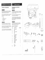
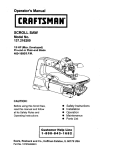
Bench
Mode_
1/2 HP (Maximum
Developed)
5 Speeds (540 = 3600 R,PoMo)
!/2 inch Chuck
104NCH DR_LL PRESS
Model No°
137o219100
CAUTmON°o
•
o
o
o
o
o
Before using this Dril! Press,
read this manual and foltow
at! its Safety Rules and
Operating Instructions.
@ustemer
Safety _nstructions
KnstatJation
Operation
Maintenance
Parts List
Espa_oi
He_p L_n÷
t °8@@°843°1682
Sears, Roebuck
Part No. 1372!910001
and Co=, Hoffman
Estates,
mL60179 USA
SECTION
GENERAL SAFETY INSTRUCTIONS
PAGE
Warranty
...................
Product
Specifications
...........
...........................................
Safety instructions
.........................................................
Accessories
and Attachments
...............................................
Carton
Contents
...........................................................
Know Your DYII Press ......................................................
Glossary
of Terms
........................................................
Assembly
and Adiustments
.................................................
•
. ..............................
Operation
...............................
Maintenance
............................................................
Troubl÷shooting
guide
....................................................
Parts
...................................................................
Espaiol
........................
"..............................
" .....
BEFORE
2
2
3
6
6
8
9
10
t6
.20
21
22
25
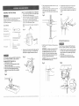
Contact a Sears Service Center for repair.
ii
1'. READ and become familiar with this entire instruction
manual. LEARN the tool's applications, limitations, and
possible hazards.
17. DON'T OVERREACH°
balance at all t._,__s.
_
2.
KEEP GUARDS IN PLACE and in working order.
3.
DON'T USE IN A DANGEROUS ENVIRONMENT.
Don't use power tools in damp or wet locations, or
expose them to rain. Keep work area well lighted.
4.
DO NOT use power tools in the presence of flammable
liquids or gases.
5.
KEEP WORK AREA CLEAN. Cluttered areas and
benches invite accidents.
]
!
6.
KEEP CHILDREN AWAY. All visitors should be kept at
a safe distance from the work area.
,
This warranty gives you specific legal rights, and you may also have other rights which vary from state to state.
,
Estates, JL 60179
g÷
SPEEDS
.........
.............
5 (540-3,600 RPM)
£aOTOR ..............
120V, 60 HZ, 6 AMPS,
HORSEPOWER ........
1/2 HP (Max. Developed)
TABLE SIZE ..........
8-!/4" x 7-1/4"
TABLE TILT ...........
450 RIGHT OR LEFT
SPINDLE TRAVEL
THROAT
.............
.....
2-3/8"
5"
BASE SIZE ...........
14-318" x 8-114"
H51GHT ...............
28-3/8"
19. CHECK FOR DA_]AGED PARTS. Before. further use of
the tool, a guard or other part that is damaged should
be carefully checked to determine that it wi!l operate
properly and perform its intended function. Check for
alignment of moving parts, binding of rnoving parts,
breakage of parts, mounting, and any other conditions
that may affect its operation. A guard or other part that
is damaged should be Properly repaired or replaced.
20. MAKE WORKSHOP KID PROOF with padlocks, master
switches, or by removing starter keys.
DON'T FORCE THE TOOL. It will do the job better
and safer at the rate for which it was designed.
USE THE RIGHTTOOL. Don't force tool or the
attachment to do a job for which it was not designed.
2t. DO NOT operate the tool if you are under the influence
of any drugs, alcohol or medication that could affect
your ability to use the tool properly.
WEAR PROPER APPAREL. DO NOT wear loose
clothing, gloves, neckties, rings, bracelets, or other
jewelry which may get caught in moving parts.
Nonslip footwear is recommended. Wear protective
hair covering to contain long hair.
22, Dust generated from certain materials can be
hazardous to your health. Always operate the drill
pres.s in a weflwentilated area and provide for proper
du#t removal. Use dust collection systems whenever
possible.
10. WEAR A FACE MASK OR DUST MASK.
Drilling operation produces dust.
1/2"
To avoid electrical hazards, fire hazards, or damage to
the tool, use proper circuit protection.
Your drill press is wired at the fac[[ory for 120V operation.
Connect to a 120V, t5 AMP branch circuit and use a
i5 AMP time delay fuse or circuit breaker. To avoid shock
or fire, replace power cord immediately if it is worn, cut or
damaged in any way.
W_AaYOUa
23. ALWAYS WEAR EYE
PROTECTION. Any drit press
can throw foreign objects into
the eyes which could cause
permanent eye damage.
ALWAYS wear Safety Goggles
(not glasses) that comply with
ANSI safety standard Z87.!. Everyday eyeglasses
have only impact-resistant lenses. They ARE NOT
safety glasses, Safety Goggtes are available at Sears.
NOTE: Glasses or goggles not in compliance with
ANSI Z87.1 could seriously hurt you when they break.
11. DISCONNECT TOOLS before servicing, and when
changing accessories, such as blades, bits, cutters,
and the like.
12, REDUCE THE RISK OF UNINTENTIONAL STARTING..
Make sure the switch is in "OFF" position before
plugging in.
13. USE RECOMMENDED ACCESSORIES. Consult the
owner's manual for the recommended accessories.
The use of improper accessories may cause risk of
injury to persons.
)i:i;;i:!ii!!i)]!;::)::::!;:
::i_::)!i,::_):i
¸¸i;::i,<Sfi::,_<:?::
i,:::i:/:_:::
¸:LI:,i:::_!:,:47
T,!,
:¸:;:::::':ii:i!:i_::):::i
'i;i:il:
)!::!:i!f:i:!i::i;
i:!:IT_)!:i:!_!:i
I:I:I:_::,
':):i
,:_):::!i:):))):ili:!i_:i!::
2 :i_:i:i
!,i_:ii::)!!::::i;i!;i::i:Tj
_::?:i::i!::<
i'::_:!::!:2_ii::i:)
¸I:::
i !I_IY_)I
U::)i,I
)::(:_::_;i:ii{:::::::::,:!;i:i
i=_::{::ii!)(i
¸;i::i!;!;!_'::::!?::
¸!::I:
?i!
i:::i:!:i:;:i':!::_%)_i:_))i);:!:i!i!)::':ii:!_
<];::
Keep proper footing and
18. MAINTAIN TOOLS WiTH CARE. Keep tools sharp
and clean for best and safest performance. Follow
instructions for lubricating and changing accessories.
i!
purchase.
CHUCK SIZE
15. NEVER LEAVE TOOL RUNNING UNATTENDED.
TURN THE POWER "OFF". Don't leave the tool untit
it comes to a complete stop.
16. NEVER STAND ON TOOL. Serious iniury coutd occur
if the tool is tipped o_'i_the cutting too! is unintentonalty
contacted.
or rental purposes, this warranty applies onfy for 90 days from the date of
Soars, Roebuck and Co., Dept. 817 WA, Hoffman
PRESS
To avoid mistakes that could cause serious injury, do not
plug the drill press in until you have read and understood
the following:
!
_fthis product is used for commercial
THE DRILL
Safety is acombination of common sense, staying alert
and knowing how to use your drill press.
FULL ONE YEAR WARRANTY
If this product fails due to a defect in material or workmanship within one year from the date of purchase, Sears
will repair it free of charge.
USING
!4. REMOVE ADJUSTING KEYS AND WRENCHES.
From the habit of checking to see that keys and
adjusting wrenches are removed from the t0ol before
turning "ON".
SAVE THESE INSTRUCTIONS
3
GROUNDING
I4. SECURE WORK. Use clamps or a vise to hold the
work when practical. It's safer than using your hand
and it Frees both hands to operate tool.
SPECnFIC SAFETY NSTRUCTMONS
FOR THE DR LL PRESS
16. MAKE SURE all clamps and locks are firmly
tightened before drilling.
17. SECURELY LOCK THE HEAD and table support to
the column, and the table to the table support before
operating the drill press.
YOUR DRILL PRESS MUST BE BOLTED securely
to a workbench. In addition, ff there is any tendency
for your drill press to move during certain operations,
bolt the workbench to the floor.
1.
2.
.
WEAR EYE PROTECTION. USE face or dust mask
along with safety goggles if drilling operation is dusty.
USE ear protectors, especially during extended periods
of operation.
4.
DO NOT wear gloves, neckties, or loose clothing.
5.
DO NOT try to drill material too small to be securely
held.
6.
.
8.
9.
DO NOT install or use any drill bit that exceeds
!75 mm (7") in length or extends 150 mm (6") below
the chuck jaws. They can suddenly bend outward or
break.
DO NOT USE wire wheels, router bits, shaper cutters,
circle (fly) cutters, or rotary planers on this drill press.
WHEN;cutting a large piece of material make sure it
is fully'supported at the table height.
10. DO NOT perform any operation freehand. ALWAYS
hold the workpiece firmly against the table so it will
not rock or twist. Use clamps or a vise for unstable
workpieces.
11. MAKE SURE there are no nails or foreign objects in
t2
CLAMP WORK:PIECE OR BRACE against the left
side of the column to prevent rotation. If it is too short
or the table is tilted, clamp solidly to the table and
use the fence provided,
13. IF THE WORKP1ECE overhangs the table such that
it will fall or tip if not held, clamp it to the table or
provide auxiliary support.
I9. BEFORE STARTING the Operation, jog' the motor
switch to make sure the drill bit does not wobble or
vibrate.
20. LETTHE
SPINDLE REACH FULL SPEED before
starting to drill. If your drill press makes an unfamiliar
noise or if it vibrates excessively, stop immediately,
turn the drill press off and unplug. Do not restart until
the problem is corrected
:
ALWAYS keep hands out of the path of a drill bit.
Avoid awkward hand positions where a sudden slip
could cause your hand to move into the drill bit.
the part of the workpiec.e to be drilled.
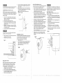
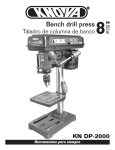
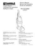
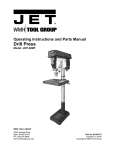
DO NOT MODIFYTHE PLUG PROVIDED. tf it wilt no[ fit [he
receptacle, have the proper receptacle installed by a
qualified electrician.
18. NEVER turn your drill press on before clearing the
table of all objects (-tools, scraps of wood, etc.)
THIS DRILL PRESS is intended for use in dry
conditions, indoor use only.
IMPROPER CONNECTION of the equipment grounding
conductor can result in risk of electric shock. The
CAUTION: In all cases, make certain the receptacle in
question is property grounded. If you are not sure have a
codified electrician check the receptacle.
conductor with the green insulation (with or without yeltow
stripes) is the equipment grounding conductor. If repair
or replacement of the electric cord or plug is necessary,
DO NOT connect the equipment grounding conductor to
a live terminal.
This drill press is for indoor use only. Do not expose to
rain or use in damp locations.
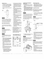
Fig° A
3-Prong Plug
CHECK with a qualified electrician or service personnel if
you do not completely understand the grounding instructions,
or if you are not sure the tool is properly grounded.
::}i
21, DO NOT perform layout assembly or set up work on
the table while the drill press is in operation.
22. USE RECOMMENDED SPEED for drill accessory and
workpiece material. SEE INSTRUCTIONS that come
with the accessory.
23. WHEN DRILLING large diameter holes, clamp the
workpiece firmly to the table. Otherwise, the bit may
grab and spin the workpiece at high speed. DO NOT
USE fly cutters or multiple-part hole cutters, as they
can come apart or become unbalanced in use.
24. MAKE SURE the spindle has come to a complete
stop before touching the workpiece.
25. TO AVOID INJURY from accidental starting, always
turn the switch "OFF" and unplug the drill press before
installing or removing any accessory or attachment
or making any adjustment.
26.
KEEP GUARDS lN PLACE and in working order.
27. USE ONLY SELF-EJECTING
provided with the drill press.
TYPE CHUCK KEY as
q
USE ONLY 3oWIRE EXTENSION CORDS THAT HAVE
3-PRONG GROUNDING PLUGS AND 3opOLE
RECEPTACLES THAT ACCEPT THE TOOL'S PLUG.
REPAIR OR REPLACE DAMAGED OR WOF_?,_CORD
IMMEDIATELY.
(
Grounding
Prong
Properly
Grounded
3-Prong Receptacle
F_9. B
GU_DEUNES
FOR EXTENSION
CORDS
Grounding Lug
Make sure your extension cord is in good condition.
When using an extension cord, be sure to use one heaw
enough to carry the current your product wil! draw. An
undersized cord will cause a drop in line voltage resulting
in loss of power and overheating. The table below shows
the correct size to use according to cord length and
nameplate ampere rating. If in doubt, use the next heavier
gauge. The smaller the gauge number, the heavier the cord.
I
Be sure your extension cord _s property wired and in
good condition. Always replace a damaged extension
cord or have it repaired by a qualified person before
using it. Protect your extension cords from sharp objects,
excessive heat and damp or wet areas.
is Connected to a
Known Ground
Make Sure This
2-Prong
Receptacle
This toof must be grounded while in use to protect the
operator from electrical shock.
(when using 120 volts only)
Use a separate electrical circuit for your tools. This circuit
must not be less than #t2 wire and should be protected
with a 15 Amp time tag fuse. Before connecting the motor
to the power line, make sure the switch is in the "OFF"
position and the electric current is rated the same as the
current stamped on the motor nameplateo Running at a
lower voltage will damage the motor.
SAVE THESE
SAVE THESE INSTRUCTmONS
! }:i::i::':::: :
z
This tool is intended for use on a circuit that has a
receptacle iike the one illustrated in FIGURE A.
FIGURE A shows a 3-prong electrical plug and receptacle
that has a grounding conductor. If a properly grounded
receptacle is not available, an adapter (F_GURE B) can.
be used to temporarily connect this plug to a 2-contact
ungrounded receptacle. The adapter (RGURE B) has a
rigid lug extending from it that MUST be connected to a
permanent earth ground, such as a properly grounded
receptacle box. The temporary adapter should be used
only until a properly grounded outle_ can be installed by a
qualified electrician . The Canadian E!ectrical Code
prohibits the use of adapters.
IN THE EVENT OF A MALFUNCTION OR BREAKDOWN,
grounding provides a path of least resistance for electric
current and reduces the risk of electric shock. This tool
is equipped with an electric cord that has an equipment
grounding conductor and a grounding plug. The plug
MUST be plugged into a matching receptacle that is
properly installed and grounded in accordance with ALL
local codes and ordinances.
15. WHEN using a drill press vise, always fasten to the
table.
For your own safety, do not try to use your drill press
or plug it in until it is completely assembled and installed
according tO the instructions, and until you have read and
understood this instruction manual:
INSTRUCTIONS
:: :i :::::i: :::
:.':4
::::
Arc@ere Rating
l Total length of cord in feet
more than
not mere then
25'
100'
t 50 '
6
[
50'
0
! 18
16
16
14
6
10
10
12
18
16
16
14
14
12
12
16
| 14
12
Not recommended
±
NSTRUCT ONS
5
:::
::::::
:: :.:.:::
:::::::::::::::::::
::::::::
i
AVAILABLE
ACCESSORIES
Use only accessories recommended [or this drill press.
Follow instruction,s that accompany accessories, Use of
improper accessories may cause hazards.
UNPACKmNG AND CHECKmNG
CONTENTS
If any part is missing or damaged, do not plug the drill
press in until the missing or damaged part is replaced,
and assembly is complete.
Visit your Sears Hardware Department or see the Sears
Power and Hand _bol Catalogue for the following
accessories:
Carefully unpack the drill press and al! its parts, and
compare against the illustration below.
o Dri_ bits
o_ Hold-Down and Guide
Drill Press Vises
Clamping Kit
To protect the drill press from moisture, a protective
coating has been applied to the machined surfaces.
Remove this coating with a soft cloth moistened with
kerosene or WD-40.
Use oniy accessories designed for this drill press to
avoid injury from thrown broken parts or workpieces.
-Foavoid fire or toxic reaction, never use gasoline,
naphtha, acetone, facquer thinner or similar highly
volatite solvents to clean the drill press.
Sears may reco_.-nmendother accessories not listed in
this manual. See your nearest Sears store or Power and
!..-landTool Catalogue for other accessories.
Do not t_se any accessory unless you have completely
read the instruction or owner's manual for that accessory.
TABLE
OF LOOSE
D
E
::ii
PARTS
ITEM
DESCRIPTION
QUANTITY
A.
B.
C.
D.
E.
R
Head assembly
Base
Table
Coiumn assembly
Collar
Rack
1
t
1
1
1
1
G.
H.
I.
J.
K.
L.
M.
N.
O.
R
Loose parts bag:
Feed handles
Worm gear
Crank handle
Lock handle
Hex bolts
Fence assembly
Triangle knobs
Wing nuts
Washers
Hex keys
3
1
t
1
4
t
2
2
4
2
q
i
B
C
G
I
L
M
J"
N
K
O
Box:
Q.
Chuck key
R.
Chuck
1
t
P
Q
R
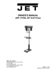
Motor
pulley
Spindle
pulley
Depth scale stop nuts
Cord clamp
Depth scale
pointer
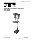
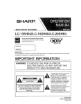
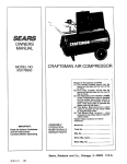
BASE - Supports the drill press. For additional stability,
holes are provided in the base to bolt the drill press to
the floor. (See "Specific Safety Instructions for Drill Presses':)
DRILL ON/OFF SWITCH - Has locking feature. This
feature is intended to help prevent unauthorized and
possible hazardous use by children and others, insert the
key into the switch to turn the drill press on.
BACKUP MATERIAL -A piece of scrap wood placed
between the workpiece arid table. The :backup board
prevents wood in the workpiece from splintering when the
drill passes through the backside of the workpiece. It also
prevents drilling into the table top.
DRILLING SPEED - Changed by placing the belt in any
of the steps (grooves) in the pulleys. See the Spir_
Speed Chart inside the belt guard.
BELT GUARD ASSEMBLY -Covers
during operation of the drill press.
FEED HANDLE- Moves the chuck up or down. If
necessary, one or two of the handles may be removed
whenever the workpiece is of such unusual shape that it
interferes with the handtes.
the pulleys and belt
BELT TENSION - Refer to the "Assembly" Section,
"Installing and Tensioning Belt."
L!
!
Depth scale
Belt
tension
knob
Depth stop
Head lock
screw
Cove r
CHUCK - Holds the drill bit or other recommended
accessory to perform desired operations.
ON/OFF
switch w/key
Bevel scale
Table suppo_
_b
\
tor
_._ii
Eeed handle
Chuck
i
_
_ B elt
tenl_/°nb
Head lock
screw
CHUCK KEY - A self-ejecting chuck key which will pop
out of the chuck when you let go of it. This action is
designed to help prevent throwing of the chuck key from
the chuck when the power is turned "ON". Do not use
any other key as a substitute; order a new one if damaged
or lost.
SPINDLE SPEED - The R.RM. of the spindle.
SPRING CAP - Adjusts quill spring tension(
TABLE - Provides working surface to support workpiece.
TABLE BEVEL LOCK - Locks the table in any position
from 0 °- 45 °.
COLUMN COLLAR - Holds the rack to the column.
Rack remains movable in the collar to permit table
support movements.
TABLE CRANK HANDLE - Elevates and lowers table.
Turn clockwise to elevate table. Support lock must be
released before operating crank.
COLU_N SUPPORT -Supports the column, guides the
rack and provides mounting holes for cotumn to base.
DEPTH SCALE - lndic_,tes ,depth of hole being drilled
Table
RACK -- Combines with gear mechanism to provide easy
elevation of the table by the hand operated table-crank.
COLUMN -Connects the head, table, and base on a
one-piece tube for easy alignment and movement.
Bevel lock
Base
HEAD LOCKS - Locks the head to the column. ALWAYS
lock the head in place while operating the drill press.
REVOLUTION PER MINUTE (R,P,M.)-The
number of
turns completed by a spinning object in one minute.
indle
Column collar
Support .eck handle
TENS!ION KNOB -Tightening the knob locks
the motor bracke t support maintaining correct belt distance
and tension.
BEVEL SCALE - Shows the degree of table tilt for bevel
operations. The scale is mounted on the side of the arm.
Feed stop rod
Feed spring
_LT
FENCE - Attaches to the table to a i:gn the workpiece or
for fast repetitive drilling. Removable. Remove fence when
it interferes with other drill press accessories.
DEPTH SCALE POINTF=R -o indicates the drilling depth
by pointing to the depth scale,
DEPTH SCALLE STOP NUTS - Locks the depth scale to
selected depth.
TAB&E SUPPORT LOCK = Tightening locks the table
support to the column. Always have it locked in place
while operating the dril! press,
TABLE SUPP©RT = Rides on the column to s{jppol:t the
table.
WORKP_ECE = Materia! being drilled. '
DRILL BiT - The cutting too! used in the drill press to
make holes in a workpiece.
Fence backstop
Fence end__
Column support
,: !.
::::,
:
:; :_::::_:::
:::_i<!:ii:
:
::::::::iii?_i::::::i:
',: :
: :
:
9 :::::::::::::::::::::::::::::::::::::::::::::::::::::::::::::::::::::::::::::::::::::::::::::::::::::::::::::::::::::::::
,
6_
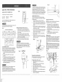
ASSEMBLY
tNSTRUCTMONS
For your own safety, never connect plug to power source
outlet until af! assembly and adjustment steps are
completed, and you have read and understood the safety
and operating instructions.
TABLE TO COLUMN ASSEMBLY (FIG. B THROUGH F)
1. Locate the worm gear, table crank, and table support
lock handle from the loose parts bag.
2. Insert the worm gear (1)into the table crank handle
hole (2) from inside the table support (3). Make sure
the worm gear (!) meshes with the inside ge&r.
3. Insert the table support Jock handle (4) into the hole
at the _ear of the table support. Tighten.
Slide the table support assembly with the rack (1,3,5)
together onto the column.
Engage the bottom of the rack (5) with the tip of the
column support (6). Tighten the support lock
handle (4) to lock the table support assembly to the
column.
9.
Install the table crank handle (9) to the worm gear
shaft (1) on the side of the table support (6).
Line up the flat side of the shaft with the set screw (!0)
in the crank handle and tighten the screw with a hex
wrench.
Fig. F
Fig. D
•
IO
4
3
NOTE: Table removed from support in illustration for
clarity.
TOOLS NEEDED
8.
i
Fig_ B
[
c_ot[edscrewdriver
8" & 10" Adjustabfe wrenches
J
Combination wrench
Combination square.
_NSTALLING THE HEAD (FIG. G)
/i _
:1
,
Socket
wrench-
with 23 ram. socket
4_
The Drill Press is very heavy and MUST be lifted with the
help of 2 PEOPLE OR MORE, to safely assemble it.
COLUMN SUPPORT TO BASE (FIG. A)
!. Position base (1)on floor.
2. Place column (2) on 10ase,aligning holes in column
support with holes in base,
3. , Locate four Ionghex bolts (3) from loose parts bag.
4. Place a bolt in each hole through the column
support and the. base. Tighten with an adjustable'
wrench.
Place the rack (5) in position inside the table support (3),
making sure the worm gear (1) on the inside of the
table support is engaged with the teeth of the rack.
Fig. C
5
'
1
Install the collar (7)to the top end of the rack (5) on
the column.
IMPORTANT: The bottom of the collar MUST NOT
be pushed all the way down onto the top of the
rack. MAKE SURE the top of the rack is under
the bottom of the collar and that there is enough
clearance to allow the rack to freely rotate around
the column. Tighten the set screw (8).
The Drill Press is very heavy and MUST be lifted with
the help of 2 PEOPLE OR MORE,. to safely assemble it.
1
2.
Carefully lift head,(1) above the column (2) and slide
it onto the column. Make sure the head slides down
over the column as far as possible. Align the head
with the base.
Using the hex wrench, tighten the two head
lock set screws (3) on the right side of the he,_d.
CAUTION: To avoid column or collar damage, DO
NOT OVERTIGHTENthe
set screw.
Fig. G
Fig. E
/-
..........._...- 8
"--""-_"'-_"J-"-7
Fig. A
5
2
3
|
r,:_;, _ : i::':;:k
; ::
:-;J
i::: :
d : q : o::::
i://: {:v _i>::'ij:i,
_ I!
::
::::::
:::: :]
:::'::
_NSTALMNG FEED HANDLES (FIG. H)
1. Locate three feed handles in the loose parts bag.
2. Screw the feed handles (1) into the threaded holes (2)
in the hub (3). Tighten.
,
FENCE ASSEMBLY (F_G°M}
t. Determine the desired location for the fence (.1).
2. Aiign the mounting holes of the fence over the table
top slots.
3. Place a washer (2) on the threaded end of the knob (3).
Insert the knob through the mounting hole of the fence
and the table slot.
Using a rubber maltet, plastic-tipped hammer, or a
block of wood and a hammer, firmly tap the chuck
upward into position on the spindle shaft.
Fig, K
4.
Place a washer and wing nut (4) on the knob from '
under the table.
5.
Repeat for the other knob and tighten.
CAUTION: Make sure there are no foreign particles
sticking to the surfaces. The slightest piece of dirt on
any of these surfaces will prevent the chuck from
seating properly. This will cause the drill chuck and
bit to wobble. If tapered hole is extremely dirty, use a
cleaning solvent.
MOUNTING DRILL PRESSTO WORK SURFACE (FIG. L)
1. If mounting the drill press to a workbench, a solid
wood bench is preferred over a plywood board, to
reduce noise and vibration.
2. Holes should be pre-drilled through the supporting
surface.
3. The hardware to mount this drill press is NOT
supplied with the tool. The hardware as shown in
the illustration should be used:
Fig.I
Fig. L
2
ALIGNING THE BELT PULLEYS ,(FIG. N)
Open the t_ead cover of the Drill Press. Check alignment
of the pulleys with a straight edge (5) such as a framing
square, a level, or a piece of wood. Lay the straight edge
across the top of the pulleys. If all three pulleys are NOT
aligned:
1. Release belt pressure by loosening the belt tension
lock knobs (2)on either side of the head,
counterc!ockwise.
2. Loosen the motor mount nuts (3). Lift or lower the
motor (4) until the pulleys are in line.
3. Tighten the motor mount nuts (3) t_sing an adjustable
wrench.
E
NOTE: To avoid rattles or other noise, the motor
housing should not touch the lower belt guard
housing.
4.
5.
Lower the spindle (2) by turning the feed handles (3)
counterclockwise.
Push the chuck up onto the spindle (2).
Tap gently to ensure seat.
Open the jaws of the chuck (t) by rotating the chuck
sleeve clockwise. To prevent damage, make sure the
jaws are completely receded into the chuck.
I
1.
2.
Drill press base
Boft
3.
4.
5.
6.
7.
Flat washer
Rubber washer
Worksurface
Flat washer
Lockwasher
Hex nut
8.9. Jam nut
Retighten the belt by pulling the motor (4) toward or
away from the drill press head, until the belt deflects
approximately t/2 inch when pressed in the center.
4,
i
NOTE: Refer to the chart inside the bett guard
cover for recommended drilling speeds and
belt / pulley positions.
I
,
Ii
__
i i
.......................
E
_\
\
. Lock the belt tension lock knobs (2) by turning
clockwise.
NOTE: When the belt is new, it may be difficult to
move the belt. As the machine is used, the belt will
gain more elasticity and will be easier to adjust.
|
!
It
3.
CAUTION: All the adjustments for the operation of the
drill press have been completed at the factory. Due to
normal wear and use, some occasional readjustments
may be necessary.
To avoid injury from an accidental start, ALWAYS make
sure the switch is in the "OFF" position, the switch key is
removed, and the plug is not connected to the power
source outlet before making belt adjustments.
Fig. M
INSTALLING THE CHUCK (FIG. t, J and K)
t. Clean out the tapered hote in the chuck (1) with a
clean cloth.
2. Clean tapered surfaces on the spindle (2).
ADJ UST 'V ENT INSTRUCTIONS
Fig. N
tt
"1
6
¢h
_
5
Fig. J
2
--
,,_
........
>s
ti
3
...........
i3
:::::::::::::::::::::::::::::::::::::::::::::::::::::::::::::::::::
,
To prevent personal injury, always disconnect the plug from
the power source when making any adjustments.
SQUARING TABLE TO HEAD (FIG. O, P)
NOTE: The table and support has a predrilled hole with a
locking pin inserted for locking thetable to a predetermined
0° horizontal position. It must be loosened to change the
angle of the table.
I.
2.
3.
4.
5.
.
QU_LL RETURN SPRING (FIG, R)
The quill return spring may need adjustment if the tension
causes the quill to return too rapidly or too slowly.
t. Lower the table for additional clearance.
2, Place a screwdriver in the lower front notch (1) of the
spring cap (2). Hold it in place while loosening and
removing only the outer jam nut (3).
3. With the screwdriver still engaged in the notch,
loosen the inner nut (4) just until the notch (5)
disengages from the boss (6) on the drill press head.
To return the table to its original position, loosen the
bevel locking bolt (5). Realign the bevel scale (6) to
the 0 ° position.
Return nut (4) on locking pin to the OUTSIDE END
OF THREADS. Gently tap locking pin until it is seated
in the hole. Finger tighten nut (4).
NOTE: The table has been removed from the
illustration for clarity.
Fig. P
CAUTION: DO NOT REMOVE THIS INNER NUT,
because the spring will forcibly unwind,
Insert a 1/4", or larger diameter, precision ground
steel rod (1), approximately 3" long, into the chuck (2).
Tighten the chuck jaws.
Raise table to working height and lock.
Using the combination square (3), place one edge
flat on the table, and align the other edge vertically
beside the rod (1).
(Figure Q) If an adjustment is necessary, TIGHTEN
the nut (4) on the locking pin clockwise to RELEASE
it from the table support.
Loosen the large hex head bevel locking bolt (5).
4.
Carefully turn the spring cap (2) counterclockwise with
the Screwdriver, engaging the next notch.
5. Lower the quill to the lowest position by rotating the
feed handle in a counterclockwise direction while
holding the spring cap (2) in position,
6. If the quill moves up and down as easily as you
desire, tighten the standard nut (4) with the adjustable
wrench. If too loose, repeat steps 2 through 5 to
tighten. If too tight, reverse steps 4 and 5.
To avoid injury from an accidental start, ALWAYS make
sure the switch is in the "OFF" position, the switch key is
removed, and the plug is not connected to the power source
outlet before making belt adjustments.
BELTTENSiON
(FroG.S)
Make sure pulleys are aligned properly as shown in
Figure O on page 13.
1. To unlock the belt tension, loosen the belt tension
lock knobs (1) on both sides of the drill press head.
2. Move the motor (2) toward the front of the drill press
to loosen the belt.
3. Position the belt on the correct pulley steps for the
desired speed.
4. Pull the motor away from the drill press head until
the belt is properly tensioned.
NOTE: Belt tension is correct if the belt deflects
approximately 1/2 inch when pressed at the center.
Tighten the belt tension lock knobs (1) on both sides
of the drill press head.
,
DO NOT OVERTIGHTEN and restrict quill movement.
To prevent injury, be sure to hold the table & table arm
assembly, so it wil! not swivel or tilt.
6.
7.
Align the square to the rod by rotating the table until
the square and rod are in line.
Retighten the large hex bolt (5).
Fig. O
2
=
SPINDLE/QUILL
(FIG. Q)
Rotate the feed handles counterclockwise to lower spindle
to its lowest position. Hand support the spindle securely
and move it back and forth around its axis.
If there is too much play, do the following:
!. Loosen lock nut (1)..
2. Turn the screw (2) clockwise to eliminate the play, but
without obstructing the upward movement of the
spindle. (A little play in the spindle is normal.)
3_ Tighten the lock nut (1),
Replace the jam nut (3) and tighten against the
standard nut (4) to prevent the standard nut from
reversing.
6
1
1
Fig. Q
L
y
i,i
2
E
I
I
BEVEL SCALE
I
I
I
I
_'
...
(FIG. P)
NOTE: The bevel scale has been included to measure
approximate bevel angles. If precision is necessary,
a square or other measuring toot should be used to
position the table. To use the bevel scale (6):
I. TIGHTEN the nut (4) on the locking pin clockwise to
RELEASE it from the table support.
2. Loosen the large hex head bevel locking bolt (5).
3. Tilt the table, aligning the desired angle measurement
to the zero line opposite the scale (6).
4. Tighten the bevel locking bolt. (5).
3
4
Fig. S
.....
1
, ,,.....
,,,,,
=_
Fig. X
BASIC
DRILL
PRESS
OPERATIONS
Fig. U
SPEEDS AND BELT PLACEMENT
(FIG. T)
This drill press has 5 speeds, as listed below:
540 RPM
2610 RPM
880 RPM
3600 RPM
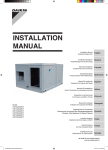
USINGTHE FENCE (FIG. W)
The fence provides a way of accurately and quickly
setting up the workpiece for more precision or repetitive
drilling operations.
1. Using the centerpunch or sharp nail, make an
indentation in the workpiece where you want to drill.
2. Lower the drill bit to align with the indentation on the
workpiece. See "HOLDING A DRILLING LOCATION"
page t9.
3. Loosen the knobs (1) and slide the fence back stop (2)
firmly against the long side of the workpiece. Tighten
the knobs when in position.
4. Loosen the wing nut (3) and slide the end stop (4) along
the fence until it is firmly against the left side of the
workpiece. Tighten the wing nut.
5. Check the accuracy by drilling a scrap workpiece.
Adjust if needed.
6. Hold with your hand or clamp the top surface of the
workpiece firmly to prevent it from lifting off the table
when the bit is raised.
1600RPM
See inside of the belt guard for specific placement of the
belts on the pulleys to change speeds.
To avoid possible injury, keep guard closed, in place, and in
proper working order while too! is in operation.
Fig.T
Belt / Pulley Position-RPM Chart
oRPM
l
80 PM
2610 RPM
1
16oo PM I
3600
......... RPM
ON / OFF SWITCH (FIG. U)
The "ON / OFF" switch has a removable, yellow plastic key.
With the key removed from the switch, unauthorized and
hazardous use by children and others is minimized.
t. To turn the drill press "ON", insert key (1) into the slot of
the switch (2), and move tile switch upward to the "ON"
position.
2. To turn the drill press "OFF", move the switch
downward.
3. To lock the switch in the "OFF" position, grasp the end,
or yellow part, of the switch toggle, and pull it out.
4. With the switch key removed, the switch wili not operate.
5. if the switch key is removed while the drill press is
running, it can be turned "OFF" but cannot be restarted
without inserting the switch key.
t
To prevent the workpiece or backup material from being
torn from your hands while drilling, you MUST position the
workpiece against the LEFT side of the column. If the
workpiece or the backup material is not long enough to
reach the column, clamp them to the table, or use the fence
provided with the drill press to brace the workpiece. Failure
to secure the workpiece could result in personal injury.
iNSTALLING DRILL BIT IN CHUCK (FIG. V)
1. With the switch "OFF" and the yellow switch key
removed, open the chuck jaws (1) using the chuck
key (2). Turn the chuck key counterclockwise to open
the chuck jaws.
2. Insert the drill bit (3) into the chuck far enough to
obtain maximum gripping by the jaws, but not far
enough to touch the spiral grooves (flutes) of the drill
bit when the jaws are tightened.
3. Make sure that the drill is centered in the chuck.
4. Turn the chuck key clockwise to tighten the jaws.
To avoid injury or accident by the chuck key ejecting
forcibly from the chuck when the power is turned "ON", use
only the self-ejecting chuck key supplied with this drill
press. Always recheck and remove the chuck key before
turning the power "ON".
Fig. W
i=
2
Depth scale method
(FIG. Y)
NOTE: With the chuck up, the tip of the drill bit must be
just slightly above the top of the workpiece.
1.
2.
3.
4.
With the switch "OFF", turnthe feed handle until
the pointer (7) points to the desired depth on the
depth scale (4). Hold the feed handles in that position.
Spin the lower nut (3) down to contact the depth stop
lug (6) on the head.
Spin the upper stop nut (5) against the lower stop nut
and tighten.
The and drill bit will now stop after traveling the
distance selected on the depth scale.
Drilling
a hole
Using a center punch or a sharp nail, dent the workpiece
where you want the hole. Before turning the switch on,
bring the drill bit down to the workpiece, lining it up with
the hole location. Turn the switch on and pull down on
the feed handles with only enough effort to allow the drill
to cut.
FEEDING TOO SLOWLY might cause the drill bit to turn.
FEEDING TOO RAPIDLY might stop the motor, cause the
belt or drill to slip, tear the workpiece loose, or break the
drill bit. When drilling metal, it will be necessary to
lubricate the tip of the drill bit with oil to prevent it from
overheating.
Fig.Y
Fig.V
DRILLING TO A SPECIFIC DEPTH
Drilling a blind hole (not afi the way through workpiece)
to a given depth can be done two w#ys:
2
i
Always lock the switch "OFF" when the drill press is not in
use. Remove the key and keep it in a safe place.
tn the event of a power failure, blown fuse, or tripped circuit
breaker, turn the switch "OFF' and remove the key, preventing
an accidental startup when the power comes on.
i
i
Workpiece method (FIG. X and Y)
1. Mark the depth of the hole on tt_e side of the
workpiece (1).
2. With the switch "OFF", bring the drill bit (2) down
until the tip is even with the mark.
3. Hold the feed handle at this position:
4. Spin the lower nut (3) down to contact the depth stop
lug (6) on the head.
5, Spin the upper nut (5) down and tighten against the
lower nut. (3)
6. The drill bit will now stop after traveling the distance
marked on the workpiece.
4
6
4
REMOVING
CHUCK(FIG.Z)
1. Withtheswitch"OFF",openthejawsofthechuckas
wideaspossible
byturningthechuckcounterclockwise.
2. Tapthechuck(1)lightlywitha plastictippedhammer
atthetopofchuck,untilthechuckreleases.
NOTE:Placeonehandbelowthechucktocatchit when
it fallsout.
Fig. Z
b,
c.
d.
e.
f.
g.
h.
To avoid injury from an accidental start, ALWAYS make
sure the switch is in the "OFF" position, the switch key is
removed, and the plug is not connected to the power
source outlet before removing or installing the chuck.
BASIC OPERATnON
i.
j.
INSTRUCTIONS
To get the best results and minimize the likelihood of
personal injury, follow these instructions for operating your
drill press.
5.
6.
For your own safety, atways observe the safety
INSTRUCTIONS listed here and on pages 3, 4, and 5
of the instruction manual.
7.
YOUR PROTECTION
POSITIONING THE TABLE AND WORKPiECE
(FIGURE AA and IBB)
1. Lock the table (!) to the column (2) at a position so
the tip of the drill bit (3) is just above the top of the
workpiece (4).
2. ALWAYS place a BACK-UP MATERIAL (scrap wood)
on the table beneath the workpiece. This will prevent
splintering or heavy burring on the underside of the
workpiece. To keep the back-up material from spinning
out of control, it MUST contact the LEFT side of the
column.
Whenever possible, position the WORKPIECE to
contact the left side of the column. If it is too short
or the table is tilted, use the fence provided or
clamp solidly to the table, using the table slots.
When using a drill press vise, always fasten it to
the table.
Never do any work freehand (hand-holding the
workpiece rather than supporting it on the table),
except when polishing.
Securely lock the head and table support to the
column, and the table to the table support, before
operating the drill press.
Never move the head or the table while the tool
is running.
Before starting an operation, jog the motor switch
to make sure the drill or other cutting tool does
not wobble or cause vibration.
tf a workpiece overhangs the table so it will fall
or tip if not held, clamp it to the table or provide
au.'kiliary support.
Use the fence provided or other fixtures for
unusual operations to adequately hold, guide,
and position workpiece.
Use the SPINDLE SPEED recommended for the
specific operation and workpiece material. Check
the panel on the inside pulley cover or the chart
below for drilling speed information.
For accessories, refer to the instructions provided
with each accessory.
1.
2.
3.
4.
DrillBit
Diam.
(Inches)
1/16
If any part of your drill press is missing, malfunctioning,
damaged or broken, stop operation immediately until
that part is properly repaired or replaced.
Never place your fingers in a position where they
could contact the drill bit or other cutting too]. The
workpiece may unexpectedly shift, or your hand
could slip.
To avoid injury from parts thrown by the spring, follow
instructions exactly when adjusting the spring tension
of the quill.
To prevent the workpiece from being torn from your
hands, thrown, spun by the tool, or shattered, always
properly support your workpiece as follows:
a.
3600
3600
1/8
2610
1600
3/I 6
1/4
i
I
680
3/8
1
For small pieces that cannot be clamped to the table,
use a drill press vise (optional accessory).
4.
5.
The drill press vise MUST be clamped or botted to the
table to avoid injury from a spinning workpiece, or
damaged vise or bit parts.
Remove the drill press fence when it interferes with other
driti press accessories.
,
FEEDING
t. Pull down the feed handles with only enough effort to
allow the driJi bit to cut.
2. Feeding too slowly might cause the drill bit to burn.
Feeding too rapidly might stop the motor, cause the
belt or drill to slip, or tear the workpiece loose and
break the drill bit.
3. When drilling metal, it may be necessary to lubricate
the drill bit tip with motor oil, to prevent burning the tip.
1600
26!0
880
Tilt the table, aligning the desired angle measurement
to the zero line opposite the scale (4). Tighten the bevel
locking bolt.
To return the table to its original position, loosen the
bevel locking bolt (3). Realign the bevel scale (4) to
the 0 ° position,
Loosen the nut (2) on the locking pin to the OUTSIDE
END OF THREADS. Gently tap the locking pin until it
is seated in the hole. Finger tighten the nut.
To avoid injury from spinning work or toot breakage, always
clamp workpiece and backup material securely to the
table before operating the drill press with the table tilted.
Fig. BE}
2610
5/16
1/2
3600
Fig. CC
3.
Alum.,Zinc,Brass iron,Steel
To use the table in a bevel (tilted) position; TIGHTEN
the nut (2) on the locking pin clockwise to RELEASE
it from the table support.
Loosen the large hex head bevel Jocking bott (3).
To prevent injury, be sure tO hold the table & table arm
assembly, So it will not swivel or tilt.
i
Material
Wood
2.
Fig. AA
SPEED TABLE (rpm)
(FIGURE CC}
NOTE: The table and support (1) has a predrilled hole
with a locking pin inserted for locking the table into a
predetermined 0 ° horizontal position.
To prevent the workpiece or backup material from being
torn from your hands while drilling, you MUST position it
against the teft side of the column. If the workpiece or
the backup material is not long enough to reach the
column use the fence provided with the drill press to
brace the workpiece., or clamp it to the tableo Failure to
do this could result in personal injury.
Never climb on the drill press table, it could break or
pull the entire drill press down on you.
Turn the motor switch "OFF", and put away the switch
key when leaving the drill press.
To avoid injury from thrown work or tool contact, do
not perform layout, assembly, or set up work on the
table while the cutting tool is rotating.
DRILUNG
TILTING THE TABLE
1,
ii
3.
To avoid being pulled into the power toot, do not wear
loose clothing, gloves, neckties, or jewelry. Always tie
back long hair.
HOLDING A DRiLMNG LOCATION
1. Using a Centerpunch or sharp nail, make an
indentation in the workpiece where YoUwant the hole.
2. Using the feed handles, bring the drill down to align
with the indentation before turning the drill "ON".
540
Always position BACKUP MATERIAL (used
beneath workpiece) so that it contacts the left side
of the column, or use the fence provided and
clamp to brace a smaller workpiece.
19
t8
[
:!
-i
TROUBLESHOOTING
MA NTAH a NG YOUR DR LL PRESS
GUIDE
To aveid shock or fire hazaizd, if the power cord is worn
or cut in any way, have it replaced immediately.
For your own safety, turn the switch OFF and remove the
plug from the power source outlet before maintaining or
_ubricating your drill press.
LUbrICATiON
Frequentiy blow out using an air compressor or dust
vacuum, any dust that accumulates inside the motor.
A!l of the drill press ball beadngs are packed with 9tease
at the factory. They require no further k_bdcation.
A coat of automotive paste wax applied to the table and
column will help to keep the surfaces clean.
Periodically lubricate the 9ear and rack, table elevation
mechanism of the spindle and the rack (teeth) of the quill.
To avoid injury from an accidental start, turn the switch OFF and always remove the plug from the power source
before making any adjustments,
o Consult your local Sears Service Center if for any reason the motor will not run.
PROBLEM
PROBABLE
Noisy operation.
t.
CAUSE
Incorrect belt tension.
2. Dry spindle.
3. Loose spindle pulley.
4.
Drill bit burns.
Run out of drill bit point dr!lied hole not round.
:i
!
} j
i !=
Loose motor pulley.
t.
Incorrect speed.
2.
3.
4.
5.
Chips not coming out of hole.
Dull drill bit.
Feeding too slowly.
Not lubricated.
REMEDY
1. Adjust tension. See Section
"ASSEMBLY - TENSIONING BELT"
2. Lubricate spindle. See Section "LUBRICATION".
3. Check tightness of retaining nut on pulley, and
tighten if necessary.
4. Tighten set screw in motor pulley.
1. Change speed. See Section "BASIC DRtLL
PRESS OPERATION - SPINDLE SPEEDS"
2. Retract drill frequently to clear chips.
3. Resharpen drill bit,
4, Feed fast enough - allow drill to cut.
5. Lubricate drill. See Section "BASIC DRILL
PRESS OPERATION - FEEDING"
1. Resharpen drill bit correctly.
Hard grain in wood or
lengths of cutting flutes
and/or angles not equal.
2. Bent drill bit.
2. Replace drill bit.
Wood splinters on
underside,
1. No backup material
under workpiece.
1. Use backup material. See Section
"BASIC DRILL PRESS OPERATION",
W,/orkpiece torn
loose from hand.
1. Not supported or
clamped properly.
1. Support workpiece or clamp it. See Section
"BASIC DRILL PRESS OPERATION".
Drill bit binds in workpiece.
1. Workpiece pinching drill bit,
or excessive feed pressure.
2. Improper belt tension.
1. Support workpiece or clamp it. See Section
"BASIC DRILL PRESS OPERATION".
2. Adjust tension. See Section
"ASSEMBLY - TENSIONING BELT."
Excessive drill bit
runout or wobble.
!. Bent drill bit.
2. Worn bearings.
3. Ddtl bit not properly
installed in chuck.
4. Chuck not properly installed.
!. Use a straight drill bit.
2. Replace bearings.
3. Install drill properly. See Section "BASIC DRILL
PRESS OPERATION" and "ASSEMBLY".
4. lnstail chuck properly. See Section
"ASSEMBLY -INSTALLING THE CHUCK".
Quill returns
too slow or too fasL
1. Spring has improper tension.
1. Adjust spring tension. See Section"ASSEMBLYADJUSTMENTS - QUILL RETURN SPRING":
Chuck will not stay
attached to spindle.
It falls off when
trying to install.
!.
1. Using a household detergent, clean the
tapered surface of the chuck and spindle to
remove all dirt, grease and oil. See Section
"ASSEMBLY - INSTALLING THE CHUCK"
.
Dirt, grease, or oil on the
tapered inside surface of
chuck or on the spindle's
tapered surface.
!0"
10"
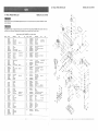
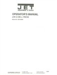
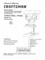
DRILL
PRESS
PARTS
MODEL
LiST
When servicing use only CRAFTSMAN
product damage.
replacement
DRILL PRESS
PARTS LIST
MODEL
NO. !37.2!9100
NO. 137.219100
parts. Use of any other parts may create a HAZARD or cause
'74_
Any attempt to repair or replace electrical parts on this Drill Press may create a HAZARD unless repair is done by a
qualified service technician. Repair service is available at your nearest Sears Service Center.
69
Always order by PART NUMBER, not by key number
Key No.
Part No.
Description
1
2
3
4
5
10300105
10300202
10300401
2601BBDAg0
10300603
Base
Co}umn holder
Body column
Hex, hd. boil
Table bracket
6
7
8
9
10
10300701
1030080t
10300901
10601009A1
2603BBLA38
Gear
Gear shaft
Worm
Crank handle ass'y
Hex, soc. set screw
Size
M8x1.25-25
...............................................................................................................................
Qty.
Key No,
Part No.
Description
1
I
1
4
t
56
57
58
59
60
260t BBDAA9
2501NBDN27
2701FBD113
10307908
2571 MNC307
Hex. hd, bolt
Flal washer
Hex. nut
Motor pulley
Paraltef key
6!
62
63
64
65
2603BBLA37
10808301
2668BBDA24
2807BB 06H2
2805U5HNt6
Hex. soc. set screw,
Clamp-cord
Cr. re. pan hd. screw
Power cable
Terminal
,
t
1
t
!
1
M6×1.0-t0
...............................................................................................................................
11
12
13
14
15
2601QBDS81
10601401
2701QZD506
10301603
2658MZDU36
Hex. hd. bolt
Location pin
Hex. nut
TiEting scale
Drive screw
i
I/2xl 2UNC-7/8
t/4x20UNC
T=4.7
I
1
1
1
2
16
17
18
t9
20
10602001
10302135
10302210
1030230 t
2603BBLA37
Table lock handle
Table
Rack
Rack ring
Hex. soc. se! screw
i
M6x1.0-8
1
1
1
1
1
...............................................................................................................................
21
22
23
24
25
10302510
2603BBLA52
10303202
10604201
10303401
Head
Hex. soc, set screw
Motor rod
Shifter bolt
Motor base
,
M8x1.25-8
1
2
2
2
1
26
27
28
29
30
2502ABC410
2701FBDlt0
10303701
10303825
2536MBE611
Spnng washer
Hex. nut
Hub
Feed shaft
Spring pin
31
32
33
34
35
10304301
10304411
10304502
10304901
Not _ssue
Handle bar
Gripe
Scale ring
Coil spring
M10x1,5 T=8
2
2
t
1
1
3
3
1
1
...............................................................................................................................
36
37
38
39
40
!0305001
!0305114
10305206
2701QZD611
10305401
Spring cap
Shaft seat
Spring retainer
Hex. nut
Quill set screw
41
42
43
44
45
270t FBDt 13
10305602
10305701
10305807
200tZZ620I
Hex. nut
Quill
Rubber washer
Spindle
Bail bearing
46
47
48
49
50
20015Z6201
2570BBN111
2570BBN117
10306512
2001 ZZ6203
Bail bearing
C-ring
C-ring
Driving sleeve
Ball bearing
5t
52
53
54
55
t030670t
10306901
t0307005
2t350NQ132
8204121104
Collar
P0ttey set nut
Spindle pulley
Chuck
Motor
i
1i2x20UNF T=8
M8xt .25-18
M8x1.25, T=6.5
4
8
4
1
1
M6x1.0-8
M5x0.8-12
2898DH7G06
10308805
2668BBDA24
10309009A1
Rocker switch
Switch box
Cnre, pan hd. screw
Pulley ass'y
M5x0.8-12
70
2.641BBDA41
71
72
73
2603BBLA52
2501 NNVN 11
10208302
.........
Cr. re. round
washer hd. screw
Hex. soc. set screw
Knob
Clamp-cord
10#24UNC_3/8"
4
M8x1.25-8
t
4
2668BBDA23
10511201
264 t 8BDA3£
2572ARK320
Cr. re. pan hd, screw
Chuck key holder
Cr. re. round
washer hd, screw
V-belt
M5x0.8-8
3
1
1
M6x1.0q 8
.20
6
"392
1
....................................................................................................................................
78
79
10312704
2661MBDEt1
80
81
2136ADD103
2536MBE623
Switch cover
Or. re. truss hd,
tapping screw
Chuck key
Spring pin
82
83
84
85
86
16932802
2501NBDN31
10838201
2702FBB108
2672BBDA40
Lock knob
Fiat washer
Parallel bracket
Wing nut
Cap hd. sq, neck bolt
M4x16-t2
1
2
93
1
2
MBxl.25
M6x1.0-16
2
4
1
2
1
822,,,,
1
t
834 _
i
i
2
i
1
....................................................................................................................................
2668BZDA23
2504MZC005
Plate
Wing nut
Not msue
Cr. re. pan hd. screw
M5x0.8-8
External tooth lock washer
92
93
94
95
96
2701FBD106
10301004
105/8401
t 020t 20!
2602BBLA27
Hex. nut
Set bolt
Nut
Pointer
Hex. soc. hd. cap bolt
t
t
t
i
2
97
98
99
100
1OI
10361701
2138MBL703
2138MBL704
28605AH071
!0384901
Set nag
Wrench hex.
Wrench hex.
Switctl key
ScaJe
1
1
1
1
1
1
102
2801ABRF04
137219100001
Strain relief
Owner's manual
2
1
"
67
t ..........................................................................................................................
10838501
2702FBDt06
!
1
t
1
I
232
1
1
2
1
87
88
89
90
91
1
1
1
2
!
1
1
1
1
1
1
....................................................................................................................................
77
i
Qty,
....................................................................................................................................
74
75
76
...............................................................................................................................
5/16x7/8-5/64
M8xl.25, T=6.5
....................................................................................................................................
66
67
68
69
...............................................................................................................................
Size
Not shown
M6x1.0, T=5
M10xl.5-2B
MBx0.8=_6
2
2
]
]
852,_
I
j54
YJ
80