1
Save Thls Manual _'X
or Future Reference
• SF RS
owner's
manual
MODEL NO.
113.228360
WOOD LATHE
it
i liiii
,ii
lul
Serial
Number
Model and serial
number
may be found on back of
headstock assembly.
You shouldrecordboth
model and serial
number in
a safeplace forfutureuse.
CRAFTSMAN
12-INCH
WOOD LATHE
FOR YOUR
SAFETY'.
READ ALL
INSTRUCTIONS
CAREFULLY
• assembly
• operating
• repair parts
J
Sears, Roebuck and Co., Hoffman Estates, IL 60179 U.S.A.
Part No, SP5110
Printed in U.S,A. 5195
FULL ONE YEAR WARRANTY
ON CRAFTSMAN
WOOD
LATHE
If within one year from the date of purchase, this Craftsman Wood Lathe fails due to a defect
in material or workmanship, Sears will repair it, free of charge.
WARRANTY SERVICE IS AVAILABLE BY SIMPLY CONTACTING THE NEAREST SEARS SERVICE CENTER/DEPARTMENT THROUGHOUT THE UNITED STATES.
This warranty applies only while this product is used in the United States.
This warranty gives you specific legal fights, and you may also have other rights which
vary from state to state.
Sears, Roebuck and Co., D/817 WA Hoffman Estates, IL 60179 U.S.A.
=
illll
,ill
i
ii
ii
, i,i
i
ii
i
GENERAL SAFETY INSTRUCTIONS FOR POWER TOOLS
1, KNOW YOUR TOOL
Read and understandowner'smanual and labels
affixed to the tool. Learn its application and limitations as well as its specific potential hazards peculiar to this tool.
2. GROUND THE TOOL
Thistool is equipped withan approved 3-condu ctor
cord and a 3.prong grounding type plug to fit the
proper grounding type receptac[e. The green conductor in the cord is the grounding wire, Never
connect the green wire to a live terminal.
3. KEEP GUARDS IN PLACE
- in working order, and Lnproper adjustment and
alignment.
4. REMOVE ADJUSTING KEYS AND WRENCHES
Form habit of checking to see that keys and adjusting wrenches are removed from tool before turning
it on.
5. KEEP WORK AREA CLEAN
Cluttered areas and benches inviteaccidents, Floor
must not be slippery due to wax or sawdust.
6, AVOID DANGEROUS ENVIRONMENT
Don't use power tools in damp or wet locations or
expose them to rain. Keep work area well lighted,
Provide adequate surrounding work space,
7. KEEP CHILDREN AWAY
NI visitors should be kept a safe distance from
work area,
8, MAKE WORKSHOP CHILD-PROOF
- with padlocks, master switches, or by removing
starter keys,
9. USE PROPER SPEED
This toolwill do the job better and safer when operated at the properspeed,
10, USE RIGHT TOOL
Don't force toolor attachment to do a job for which
it was not designed.
11. WEAR PROPER APPAREL
Do not wear loose clothing, gloves, neckties or
jewelry (rings, wristwatches) to get caught in moving parts. Non-slip footwear is recommended, Wear
protective hair coveringto contain long hair. Roll
long sleeves above the elbow.
12, USE SAFETY GOGGLES (Head Protection)
Wear safety qoqqtes (must comply with ANSI
13,
14.
15.
16.
Z87.1) at all times. Everyday eyeglasses only have
impact resistant lenses, they are NOT safety glass.
es. Also, use face or dust mask if cutting operation
is dusty, and ear protectors (plugs or muffs) during
extended periods of operation.
SECURE WORKPIECE
Mount workpiece securely between centers.
DON'T OVERREACH
Keep proper footing and balance at all times.
MAINTAIN TOOLS WITH CARE
Keep tools sharp and clean for best and safest
performance. Follow instructions for lubricating and
changing accessories.
DISCONNECT TOOLS
Before servicing, when changing accessories or
attachments.
17, AVOID ACCIDENTAL STARTING
Make sure switch is in "OFF" pos[tion before plug.
sing in,
18. USE RECOMMENDED ACCESSORIES
Consult the owner's manual for recommended accessorles. Follow the instructions that accompany
the accessories. The use of improper accessories
may cause hazards.
t9, NEVER STAND ON TOOL
Serious injury could occur if the tool tips over.
Do not store materials such that it is necessary to
stand on the tool to reach them.
20. CHECK DAMAGED PARTS
Before further use of the tool, a guard or other part
that is damaged should be carefully checked to
ensure that it will operate properly and perform its
intended function. Check for alignment of moving
parts, binding of moving parts, breakage of parts,
mounting, and any other conditions that may affect
its operation. A guard or other part that is damaged
should be properly repaired or replaced.
21, DIRECTION OF FEED
Apply cutting tool to the workpiece against the direction of spindle rotation.
22, NEVER LEAVE TOOL RUNNING
UNATTENDED
Turn power "OFF". Don't leave Lathe until It comes
to a complete stop.
additional safety instructions for wood turning lathes
Safety is a combination of common sense, staying alert
and knowing how your lathe works.
BEFORE
WARNING: To avoid mistakes that could result in
serious, permanent injury, do not connect power
cord until the following steps have been satisfactorily completed:
1. Assembly, mounting and alignment.
2. Learn the function and proper use of the on-off
switch, head stock, tail stock, tool rest, spur center,
cup center, tail stock ram lock, tool rest locks, index
pin, face plate and bed.
3. Read and understand all safety instructions and
operating procedures throughout the manual.
4. Read the following labels which appear on the front
and side of the lathe:
a AIwByl
before
Welt
Ihe Owner's
Opetaffng
lalely
M1¢hlmt.
goeg(H
wOr_ple¢:a
by ha_l
(p
cheek
1. To avoid injury from unexpected lathe movement:
a. Bolt the lathe to a stand or workbench that has
a rigid, flat surface for stability.
b. Fasten the stand or bench to the floor to prevent slipping, sliding, rocking or tipping during
operation.
,
c. Turn off lathe and unplug electrical cord before
moving the lathe to a new area.
Store and operate lathe indoors.
BEFORE
EACH USE:
1. Inspect your lathe. If any parts of this lathe are
missing, bent, or fail in any way, or any electrical
components do not work properly, turn off the lathe,
remove switch key, and remove power supply cord
from power supply. Replace damaged, missing or
faired parts before using the lathe again.
arid see
_hl' the workplt¢l t_'llatl thll tool flail and
olhmr msohttte pllrts_
J aOu(Ih ovI laclplill
WOlllplocea 2omll_
as ra_nd n posslb|e, I_fore Ill*¢hlng le
laoepllil.
a Hevl( mount w_pl_el
,hal rot, split,
©hocked _r h|ve kl_OtSmA)Wltyl ula Iowlst speed whQ_ Itlrtlt)g
ntw
THE
a. Turn switch "off" and remove switch key before
mounting workpiece in lathe.
p4"t ANSI
Z87.1.
a Oa nat welt S)OVel, _eckUal or loose
r*lothln_, Tll blC_ long hair,
I TJgttlirt Ill lOCks befell lurnin w "on" lithe.
ITu(h
MOVING
2. Plan your work to protect your eyes, hands, face,
ears and body.
FOR YOUR OWN SAFETY:
Manual
OR
O_
USING THE LATHE:
Read _nd gnderltend
WHEN
INSTALLING
LATHE:
WEAR YOUR
wGrkpl_¢e.
/ CRRFTSMRN
12" Wood
1 HP
MAXIMUM
Lathe
= Cast iron Construction
m 37" Between Centers
b. WEAR SAFETY GOGGLES, FORESIGHT IS
BETTER THAN NO SIGHT. Wear safety goggles, not glasses, that comply with ANSI Z87.1
(shown on package). Operating any power tool
can result in foreign objects being thrown into
the eyes which can result in permanent eye
damage. Safety goggles are available at Sears
retail catalog stores. Use of glasses or goggles
not in compliance with ANSI Z87.1 could result
in severe injury from breakage of the eye
protection.
m Ball Bearing Spindle,
Permanently Lubricated
• Belt Drive/4 Speeds
875, 1350, 2250, 3450 R.P.M,
D_VELOPED
E_¢I_:
120 y_lt I;
60 HZ
AC off)y;
7,,2 attiCS,
SPINDL_
SPEED
O
mnm_rm _
_t_,_rm_
_*IOTOR
c. For dusty operation, wear a face shield along
with safety goggles.
d. To avoid being struck by thrown workpieces or
tools:
WARNING
THESTARTING
RELAYIN THISHEADSTOCKASSEMBLY
IS A GRAVITYSENStTtV[
TYPE,NEVERTURNTHEPOW;ER
ONUNTJL
THEHEAOSTOCKASSEMBLY
HASBEEN
MOUNTEOONTHE ,BEDAND THE LATHE iS IN UPRIGHTPOSITION,
EE
1) Before turning lathe on, be positive the lathe
is set at the slowest speed for roughing a
new workpiece or for turning a remounted
workpiece.
2) Before turning the lathe on, always rotate
the workplace by hand to make sure it does
not strike the tool rest or anything else.
3
.i
o
._o
1) Use both hands spaced apart and keep a
firm hold of the turning toot.
3) Make sure centers are aligned when
tailstock and ram are locked.
2) Always support the turning tool directly on
the tool rest.
4) Make sure the spur center and cup center
are firmly seated against the workpiece and
that the tail stock is locked in place for spindle turnings.
3) Always operate the lathe so that the top of
the workpiece turns toward you (clockwise
facing the left side of the lathe).
5) Always center workpiece and use wood
free of checks, splits, cracks or knots. Use
lathe to turn wood and wood-like products
only.
4) Keep turning tools sharp.
5) Never start a cut directly at the end where
it may catch the workpiece.
6) Before mounting workpiece "rough it out"
to as "true round" as possible.
7) Always center and fasten the workpiece
securely to the face plate for face plate
turning.
8) Always position the tool rest above the centerllne of the lathe for spindle turning and
lock in place.
9) Do not try any operation when hand holding
the workpiece or applying the turning tool
to the workpiece below the level of the tool
rest.
10) Never try to remount a face plate turning
to the face plate for any reason.
11) Never try to remount spindle turnings between centers if the original centers in the
turning have been altered or removed.
12) Keep firm hold and control of the turning
tool and do not let the tool "bite" into the
workpiece.
13) Make sure all clamps and locks are tight
and there is no sideplay,
h,
Plan your hand placement so your hands will
not be where a sudden slip could cause them
to contact the workpiece.
To avoid an electrical shock, make sure your
fingers do not touch the metal prongs on the
plug when installing or removing the plug to or
from a live outlet.
Never turn your lathe "ON" before clearing the
area of all objects (tools, scraps of wood, etc.).
3, WHENEVER LATHE IS RUNNING
WARNING: Don't let familiarity (gained from frequent use of your wood lathe) cause a careless
mistake. Always remember that a careless frac.
tion of a second Is enough to cause severe Injury.
14) Never use lathe to cut workpiece into two
pieces.
a, If your lathe makes an unfamiliar noise or if it
vibrates excessively, turn off the lathe immediately. Remove switch key, Do not restart
until the problem is corrected,
15) Before turning lathe on be sure motor cover
Esinstalled and slide closed,
b, Position turning tool so it will not chatter or
kickback,
16) Make sure headstock is securely attached
to bed.
c, Always stand to the side of the turning tool.
e. To avoid being suddenly caught in the lathe:
1) Do not wear gloves, neckties or loose
clothing.
2) Tie back long hair.
3) Remove all jewelry.
4) Roll long sleeves above the elbow.
5) Keep motor cover in place.
6) Do not store turning tools where you must
reach over the revolving workpiece to select
them.
f, To avoid iniury from accidental starting always
turn switch off, unplug power cord, and remove
switch key before removing the guard, installing
or removing the workpiece, accessory or attachment, or making any adjustments:
g. Toavoid losing control of the turning tool causing
Injury:
4
6) Always use both hands spaced apart along
turning tool for leverage and balance.
d, Never position your face over the turning tool.
e. Avoid awkward hand positions, where a sudden
slip could cause a hand to move into the
workpiece.
f, Complete hand sanding of spindle turnings
BEFORE removing from the lathe using the
same or slower turning speed,
g, Never leave the lathe work area without turning
the lathe off, removing the switch key and waiting for the lathe to come to a complete stop.
4. To avoid injury use only recommended accessories
listed in the accessory section.
a, Do not mount and use a reamer, milling cutter,
wire wheel, buffing wheel or a drill bit on the
headstock spindle.
b, Use the drill chuck accessory on the tall stock
only.
c. Do not mount any drill that extends more than
6" beyond the chuck jaws.
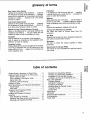
glossary of terms
Spur Center (Live Center)
Installed in the spindle of the headstock..,
supports
the workpiece on center at the headstock..,
transfers
power from the headstock to the workpiece causing the
workpiece to rotate . , , referred to as a live center
because it rotates.
Cup Center (Dead Center)
Installed in the spindle of the tail stock.,,
supports
the workplece on center at the tailstock..,
referred to
as a dead center because it does not rotate.
Spindle Turning (Turning Between Centers)
Refers to the placement of a workpiece between the
headstock and tailstock,.,
the spur center and cup
centers are used to hold the workpiece in place.
Faceplate
May be attached to the spindle of the headstock...
used to support a workpiece by the headstock alone
(tailstock not used for support).
Faceplate Turning
Made possible by the use of a faceplate for the purpose
of turning a workpiece that is to be made into a disc
shape such as a bowl..,
support of the workpiece is
by the headstock only.
O
ME
o
Headstock
It is stationary at the left end of the bed..,
contains
a spindle that the spur center fits into.,, provides the
power to rotate the workpiece.
Tailstock
Slides along the bed of the lathe..,
can be'locked to
the bed at any point..,
provides support for various
length workpieces when performing spindle turning.
Bed
Supports the headstock, tailstock and tool rest,
Turning Tool (Woodworking
Chisels)
The sharp toot used: to remove wood
workpiece.
f_om the
Tool Rest
Supports the turning tool when faceplate turning and
also when turning between centers,
Workplece
The item on which the cutting operation is being
performed.
Revolutions Per Minute (RPM)
The number of turns completed by a spinning object in
one minute.
table of contents
O
c
_o
General Safety Instructions for Power Tools ......
Additional Safety Instructions for Wood Lathe .....
Before Using the Lathe .....................
When Installing or Moving the Lathe ..........
Before Each Use .........................
Whenever Lathe is Running .................
Glossary of Terms ..........................
Motor Specifications and Electrical Requirements
Power Supply ............................
Wire Sizes ...............................
Unpacking and Checking Contents .............
Table of Loose Parts .......................
Location and Function of Controls ..............
Assembly ................................
Tools Needed for Assembly ................
Mounting Your Wood Lathe to the Workbench ..
Mounting and Assembly Tool Rest ...........
2
3
3
3
3
4
5
.6
6
6
7
7
9
10
10
10
14
Mounting and Assembling Tailstock ..........
Mounting and Assembling Headstock ........
Installation of Cup and Spur Centers .........
Installation and Use of On-Off Switch Key .....
Basic Lathe Operation ......................
Changing Speeds ........................
Belt Tension Adustment ...................
Positioning of Toolrest .....................
Mounting Wood for Spindle Turning ..........
Faceplate Turning ........................
Turning Tools .........
...................
Maintenance ..............................
Lubrication ...............................
Recommended Accessories ..................
Troubleshooting ...........................
Repair Parts ...............................
15
17
20
23
24
24
25
25
26
27
28
30
30
31
31
34
5
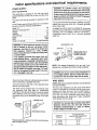
motor specifications and electrical requirements
POWER SUPPLY
Motor Specifications
This wood lathe is designed to use the type motor
supplied with the unit only. Do not use any other lype
motor.
The motor must not be converted to operate on 230
volts.
The A-C motorused in thiswood lathe is a non-reversible type having the following specifications:
Rated H.P...............................
0,5
Maximum Developed H,P ..................
1,0
Voltage .................................
120
Amperes ................................
7.2
Hertz (Cycles) .............................
60
Phase ................................
Single
RPM ..................................
3450
Rotation of Spindle ............
CounterClockwise
WARNING: To avoid electrical hazards, fire hazards, or damage to the tool, use proper circuit
protection. Your lathe ls wired at the factory for
120V operation. Connect to a 120V, 1,_AMP,
branch circuit and use a 15-AMP, tlme delay fuse
or circuit breaker.
If not properly grounded this power tool can
cause electrical shock -- particularly when used
In damp locations In proximity to plumbing. If an
electrical shock occurs there is also the potential
of a secondary hazard such as your hands contactlng the rotating workplece or the cutting tool.
Not all outlets are properly grounded. To avoid
shock or fire replace the power cord if tt Is worn,
cut, or damaged In any way.
WARNING: To maintain proper tool grounding
whenever the outlet you are planning to use for this
power tool is of the two prong type, do not remove
or alter the grounding prong in any manner. Use an
adapter as shown and always connect the ground.
ing prong to known ground.
It is recommended that you have a qualified electrician
replace the two prong outlet with a properly grounded
three prong outlet.
An adapter as shown below is available for connecting
plug to 2-prong receptacles, The green grounding lead
extending from the adapter must be connected to
a permanent g_'ound such as to a properly grounded
outlet box.
GROUNDING
3-PRONG
PLUO
_ t
LUG
I_f/tl
MAKE SURE THIS IS
CONNECTEOTOA
KNOWN
GROUND
NOTE; The adapter Illustrated is for use only if you
already have a properly grounded 2-prong receptacle,
WARNING: Do not run motor unless headstock ls
in an upright position, failure to follow this warning may burn out the motor relay and the motor.
If you are notsure thatyour outlet isproperlygrounded,
have it checked by a qualified electrician.
WIRE SIZES
Your unit is wired for 120 volts,it has a ptug lha! looks
like the one shown below.
NOTE: Make sure the proper extension cord Is used and
is in good condition,
This power tool is equipped with a 3-conductor cord
and grounding type plug listed by Underwriters
Laboratories, The ground conduclor has a green jacket
and is atlached to the tool housing at one end and to
lhe ground prong in the attachment plug at the other
end,
The use of any extension cord will cause some loss of
power, To keep this to a minimum and to prevent overheating and motor burn-out, use the table below to
determine the minimum wire size (A.W.G,) extension
cord, Use only 3 wire extension cords which have 3
prong grounding type plugs and 3 pole receptacles
which accept the tool's plug,
3-PRONG
PLUG
PROPERLY
GROUNDED
OUTLET
CAUTION: For circuits that are farther away from I
electrical service box, the wire size must be 1
Increased proportionately
In order to deliver I
-.....
ample voltage to the lathe motor.
GROUNDING
PRONG
Length o! the
Conductor
Thisplug requires a mating 3-conductor grounded type
outlet as shown above.
6
0-25
Feel
Wire Sizes Required
(American Wire Gauge Number)
120V Lines
No, 16
2.6-50 Feel
No, 14
51 - 100 Feet
No. 12
I
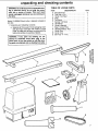
unpacking and checking contents
WARNING: To avoid injury from unexpected startIng or electrical shock, do not plug the power
cord into a source of power. This cord must
remain unplugged whenever you are working on
the lathe.
Model 113.228360 Wood Lathe is shipped complete in
one box.
1, Unpacking and Checking Contents
a, Separate all "loose parts" from packaging materials and check each item with "Table of Loose
Parts" to make sure all items are accounted for,
before discarding any packing material.
TABLE OF LOOSE PARTS
ITEM
DESCRIPTION
A Bed Machined ......................
B Tool Rest 12 In ......................
C Holder Tool Rest ....................
D Slide ..............................
E Tail Stock ..........................
F Spindle Tail Stock ...................
G Handwheel .........................
H Owner's Manual .....................
J Bag of Loose Parts ..................
K HeadstocktMotor Asm ................
L Center Spur ........................
M Center Cup ........................
N Belt Poly "V" 14 In ....................
QTY.
2
1
1
1
1
1
1
1
1
1
1
1
1
WARNING: If any parts are missing, do not
attempt to assemble wood lathe, plug in the
power cord, or turn the switch on until the missing parts are obtained and are Installed correctly.
E
K
/
G
N
7
O
List of Loose Parts in Bag #507743
O
p
Q
R
S
T
U
V
W
X
Screw Soc. Hex 1/4-20 x 3/8 ..........
Leckwasher 1/4 .....................
Nut Hex 1/4-20 .....................
Screw Soc Cap 10o32 x 1 .............
Bolt Hex HD 1/4-20 x 1 ...............
Bolt Hex HD 114-20 x 1-1/2 .... : .......
Bolt Hex HD 1/4-20 x 2-1/2 ............
Washer 17/64 x 5/'8 x 1/I6 ............
Washer .380 x 1-9164 x 7/64 ...........
Screw Pan HD Ty "B" #6 x 3/8 ........
P
1
7
7
1
2
1
4
9
1
1
W
_f
u
List of Loose Parts in Bag #507635
Y
Z
AA
AB
AC
AD
AE
AF
AG
Nut Hex 3/4-16 .....................
Center Point ........................
Key Switch .........................
Toot Rest Slide Lock 3/8-16 x 3-15/16 ,..
Tool Rest Lock 3/8-16 x 4-9/16 .........
Tait Stock Lock 3/8-16 x 2-5/6 .........
Spindle Lock 3/8-16 x 2-15/16 .........
Bracket Bed Center ..................
Tension Knob ......................
1
2
1
I
2
1
1
1
1
Z
/
/
<EC3
AA
,,.,!I PULL
II ou_
i_IIo
r
!_(
l ilo
......
_iii_,o
I,WlL
,Imlll • - _vvw.v
o
10-1_,_>
f'°
_._AC
0 0
!
Ii
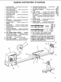
location and function of controls
1. ON-OFF SWITCH .... Turns lathe on and off and
locks lathe in off position.
2. TOOL REST SLIDE ....
Allows the tool rest to
be moved along the bed.
3. TOOL REST SLIDE LOCK ....
Locks the tool
rest slide to the bed.
4, TOOL REST LOCK .... Locks the tool rest to the
tool rest base.
5. TAILSTOCK LOCK ....
bed.
Locks the taitstock to the
6. TAILSTOCK .... Slides along the bed and supports
the workpiece for spindle turning.
7. SPINDLE LOCK ....
tailstock.
Locks the spindle in the
8. HANDWHEEL ....
Moves the tailstock spindle
into correct position for support of workpiece when
spindle turning.
9. TAILSTOCK SPINDLE ....
May be moved back
and forth by rotating the handwheel, Supports the
cup center.
10, CUP CENTER (DEAD CENTER) ....
Installed
into the tailstockspindle,., supports the workpiece
on center at the tailstock..,
referred to as dead
center because it does not rotate.
11. TOOL REST .... Supports the turning tool.
12. TOOL REST HOLDER .... Allows positioning of
the tool rest correct distance away from workpiece.
13. TOOL REST HOLDER LOCK .... Locks the tool
rest holder to the tool rest slide.
14. HEADSTOCK SPINDLE
Supports the spur
center.
_o
,z_ -,_
_ o
'-
15. SPUR CENTER ....
Installed in the headstock
spindle..,
supports the workpiece on center at
lhe headstock . . , transfers power from the
headstock to workpiece causing the workpiece to
rotate..,
referred to as a live center because it
rotates.
"_ ,_ -_
-J
,,-'
._o"_
16, MOTOR COVER .... Protects operator from contact with hot motor and drive belts.
17, SPEED CHART ....
Indicates general recommended speeds for various sizes of workpieces.
F*_£ EPt _T £ TUR P_JJO
_
_1
__
SPINDLE
SPEED
_5.l 1
--+2++o
--_4so
SF_N_E T_
--875
I
MOTOR
18. BELT TENSION ADJUSTMENT LEVER ....
Allows proper tensioning of the drive belt.
WARNING: To avoid Injury from thrown pieces,
always use lowest speed when starting a new
workpiece, using faceplate, or turning between
centers to avoid possible Injury.
9
assembly
,,.
J ,,,,
WARNING:To avoid Injury from unexpected lathe
movement and to provide necessary stability,
mountthe lathe to a stationary work bench with a
118"HEX%? WRENCH
5f32" HEX "It'
WRENCH
7t16" SOCKET
top at least i Inch thick.
The lathe should be positioned on workbench approximately 6-1/2" from front edge of workbench and the
workbench must extend past both ends of lathe.
7t16"WRENCH
SOCKETEXTENSION
Tools Needed:
#2 PHILLIPS
1/8" Hex "E' Wrench
5/32" Hex "U'Wrench
Wrench 7/16"
Socket 7/16"
Ratchet (Socket Wrench)
Socket Extension
#2 Phillips Screwdriver
Drill
5116"Drill Bit
Pliers
Adjustable Wrench
Straight Edge
Hammer
SCREWDRIVER
SOCKET WRENCH
5t16"DRILLBIT
PLIERS
ADJ. WRENCH
j ',I ',= 'iF ';i 'i_ ' ,I ',l' ,i ' ,__,p_'Tti_,]
STRAIGHT
EDGE
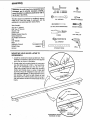
MOUNTING YOUR WOOD LATHE TO
WORKBENCH
,
Locate two sections that make up lathe bed. Place
sections on workbench.Slide thetwo ends against
each other as shown in illustration.
2. Locate center bed mounting bracket in loose parts
bag. Also locate two (2) 1/4-20 x I hex head bolts,
two (2) 1/4" lockwashers and two (2) 1/4" nuts.
Place bolts through holes in center bed mounting
bracket and through holes in center of lathe bed
as shown. Place 1/4" Iockwashers and nuts on the
bolts and hand tighten. To allow alignment of the
bed sections, nuts must be light enough to hold
bed sections in a selected position but not so tight _
that bed sections cannot be moved under the bolt / _
heads.
/ /
A
_
BED MOUNTING
BRACKET
'
"
10
.
-
.
"=_.
SHOWS'_
BACKSIDEOF BED
_1
ILLUSTRATION
....
'
J
/
/
1/4"-20x 1
HEX HEAD
-_.,_
,/
jr"
BOLT-
,
,
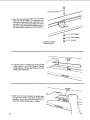
Place lathe bed near front of workbench in the position you want it to be permanently attached. The
front of lathe bed should be positioned a minimum
of 61/2" from front edge of workbench and the workbench must extend past both ends of lathe.
PtJsh the two lathe bed sections tightly together
where they meet. (See illustration.) Using a pencil
or nail mark the center of each of the five holes
onto the workbench surface.
TWO BED SECTIONS PRESSED
TIGHTLY TOGETHER
MARK HOLES AT
-THESE FIVE SPOTS
ILLUSTRATION SHOWS
REAR OF LATHE
i
ii
i
ii
i
, i
sition lathe bed so holes in bed line up with holes
in washers and holes drilled in workbench. (See
illustration.)
WARNING: Check under the workbench before
drilling holes to make sure electrical wires, gas
pipes, etc., will not be hit by drill bit.
,
5. Move lathe bed out of the way so pencil marks can
be seen. Using a ddll and 5/16" bit, drill through
work bench at each pencil mark. (Use a center
punch or nai3 to dent workbench surface at each
pencil mark before drilling holes. This will prevent
holes being drilled off center.)
6. From the loose parts bag locate four, black 114"flat
washers. Position one washer over each drilled
hole, except hole drilled at center of bed. Now po-
.
From the loose parts bag find four (4) t/4" x 2-1/2
hex head bolts. Place the four bolts through drilled
holes at each end of lathe bed and down through
workbench, (Supplied bolts are for use with a one
inch thick workbench)
From the loose parts bag find four (4) 114" fiat
washers, four (4) 1/4'° Iockwashers, and four (4)
1/4" hex nuts. Position washers and nuts under
table top onto each of the four bolts as illustrated.
(Do not tighten at this time.)
FOUR PLACES
1t4" HEX HEAD
1/4" FLAT BLACK WASHER
11
9. Fromtheloosepartsbaglocatea 114"x1-1/2"hex
headbolt,1/4"fiatwasher,
1/4"Iockwasher,
and
114"
hexnut,Placeboltthrough
centerbedmountingbracketanddownthrough
drilledholein the
workbench.
Placefiatwasher,Iockwasher, and hex
nut onto bolt from underside of table and tighten.
LOCK WASHER
HEX NUT
ILLUSTRATION SHOWS
REAR OF LATHE
STRAIGHT
EDGE
/
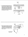
10. Place the edge of a straight edge (at least twelve
inches long) on top of bed sections. Position
straight edge so it overlaps eac_ section of the bed
equally. (See illustration,)
ill=ill
ii ii
ill i|
illll
i
i
STRAIGHT
EDGE
I1, Kneel down in front of workbench so straight edge
is at eye level. Position your hands as shown in
ilJustrationso you can move bed sections up or
down while holding straight edge in position.
12
----.-_.._..__...__..
STRAIGHT
EDGE
,\
12. Hold straight edge tightly against bed sections. Lift
up on bed sections until air gap between straight
edge and bed sections disappears. The edge of
straight edge will now be touching bed section
along full length of straight edge. (See illustration.)
If bolts that hold bed sections together have been
properly tightened, the bed sections will remain in
this position. If bed sections will not stay in this
position, tighten bolts in center of bed a little more
and complete Step 11 over again.
STRAIGHT
EDGE
ADJUSTMENT
X
f_, l', 1!, ]
/
BED
BED
AFTER
ADJUSTMENT
STRAIGHT
EDGE
,\
13. While you hold the bed sections in this position
tighten bolts that hold center bed mounting bracket
to the bed sections, The lathe bed should now be
straight and level. Use straight edge to make sure
bed sectfons did not move during bolt tightening.
14. Tighten all five nuts under workbench to secure
lathe to workbench,
BED
ILLUSTRATION SHOWS
REAR OF LATHE
t3
_,.
,,
-_
i,
HI,
H
,
iHl,,
TOOL REST SLIDE
TOOL REST SLIDE LOCK
MOUNTING AND ASSEMBLING
TOOL REST ASSEMBLY
1. From the loose parts find the tool rest slide and tool
rest slide lock. The shape and appearance of toot
rest slide lock is as shown in illustration,
Slide the tool rest slide onto right end of lathe bed.
Screw tool slide lock into tool rest slide (as shown)
until tight.
TOOL REST
SLIDE LOCK
BED
TOOL REST
SLIDE LOCK
TOOL
REST HOLDER
LOCK
2. Fromthe loose parts, locate a .380 x 1-9/16 x 7/64
flat washer {see illustration), toolrest holder and tool
rest holder lock. The appearance and shape of the
tool rest holder lock and flat washer are shown in
illustration. Attach tool rest holder and flat washer
to tool rest slide as shown,
FLAT
WASHER
TOOL
SLIDE
\
,380 X 1-9/64 X 7/64 FLAT WASHER
•14
•
BED
/
fl
•
TOOL REST LOCK
TOOL BEST
TOOL
From the loose parts locate the tool rest and tool
rest lock. See illustration for appearance of tool rest
lock. Set tool rest in tool rest holder and install tool
rest lock as shown.
,
R
LOCK
REST
LOCK
ii ill
MOUNTING
TAILSTOCK
/
AND ASSEMBLING
O
"o-'_
o.}F -_
TA1LSTOCK
oE
From the loose parts locate the tailstock, From the
loose parts bag locate tailstock lock. The appearance and shape of tailstock lock is shown in
illustration,
,
GROOVE
Slide taiistock onto right end of lathe bed. The top
surface of bed fits into V-grooves on both sides of
tailstock as shown.
..............................................
•
I
....
.--=.
TAILSTOCK
--.\
TA1LSTOCK
LOCK
,
Install tailstock lock into rear side of tailstock as
shown. The size and appearance of tailstock lock
is as illustrated.
TAILSTOCK LOCK
15
HANDWHEEL
GROOVE IN
SPINDLE
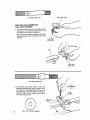
3, From the loose parts locate the handwheel and
tailstock spindle. Place handwheel into tailstock as
illustrated.
SPINDLE
GROOVE
IN SPINDLE
4, Slide spindle through opening on right side of
tailstockand thread spindle through handwheel as
shown. The groove in spindle must line up with
spindle lock hole.
SPINDLE
LOCK HOLE
SPINDLE
HANDWHEEL,.,,
SPINDLE LOCK
TAILSTOCK
5. From the loose parts bag find the spindle lock. The
appearance and shape of spindle lock isshown in
illustration. Screw lock into spinc_le lock hole as
shown, Tip of spindle lock must fit into groove in
spindle to prevent spindle rotation.
16,
LOCK
HANDWHEEL
10/32" SOCKET HEAD SCREW
6, From the loose parts bag locate a 10/32 x 1" socket
head screw, Screw the screw into the back side of
the tailstock as shown, Failure to install this bolt
will allow tailstock to slide off end of bed. Should
it slide off accidentally and fall to the floor, damage
to tailstock and cup center could result.
WARNING: The stop screw is for your protection.
It prevents the talistock from being used part way
off the end of the bed which could cause the tailstock to loosen when operated the lathe,
SOCKET
SCREW
HEAD
TAILSTOCK
ILLUSTRATION SHOWS
REAR OF LATHE
MOUNTING AND ASSEMBLING
HEADSTOCK
LOCK
0
o
"_'_"__
E
Ii
__
yos
TOC
€:_-r
K
0
1. Line up V-grooves in headstock with left end of
lathe bed. Slide headstock onto lathe bed as far
as possible,
--,
Ill
I lllll I"U
lll
I
I,,,
Ill
II I I,
HI
I
2. To be sure headstock is positioned properlyon lathe
bed, look under headstock and make sure
headstock housing is touching end of lathe bed.
(See illustration,) Now, place left hand under left
end of headstock assembly, Lift up on headstock
assembly and push it toward bed, Hold headstock
assembly in this position and proceed to step 3.
HOUSING
HEADSTOCK
BED END
f_
17
3, Place a 5/32 °' hex wrench through round opening
near power cord on backside of headstock. Insert
hex wrench into set screw located 1-1/2" inside
round opening. Tighten set screw securely using
pliers on the end of the hex wrench.
Check to see that headstock is securely attached
to lathe bed by rocking the headstock assembly
from left to right, and also up and down. If any
looseness is detected retighten the set screw.
WARNING: Failure to tighten this set screw
securely may allow headstock to move during
use. This could allow a spindle turning to come
loose, fly out, and cause injury to the operator,
/
HEX WRENCH
MOTOR COVER
4, Remove motor cover from headstock by placing
yeur right and left hand, as illustrated,and pushing
cover to the left.
FLAT AREA
5, Using a 1/8" hex-L wrench loosen the spindle pulley PULLEY
set screw, Slide the spindle pufley to the left and
lookbehind the pulley to locate the flatened section
on the spindle. The spindle pulley set screw must
SPINDLE
be aligned with and screwed down against the flat
section on the spindle when completing step 6,
SPINDLE
PULLEY
TOWARD MOTOR
18
6. Placestraightedgeagainstspindlepulleysoone
endofstraightedgeis justabovethelargesection
on motorpulley.Withstraightedgetouchingfull
faceof spindlepulley,slidespindlepulleyleftor
rightuntilthe straightedgeis in linewiththe left
sideof motorpulley,(Seeillustration,)
Keepboth
pulleysalignedwith straightedge,Usinga 118"
hex-"l"wrench,tightenset screwsecurely.Set
screwmustbepositioned
straightaboveflatsection
onspindlebeforesetscrewis tightened.
Fromtheloosepartsbagfinda 1/4-20x 3/8"he×
socketset screw.Usinga 1/8" hex-"U'wrench,
screwthissetscrewintothe spindlepulleyabove
thesetscrewyoujusttightened.Screwthesecond
setscrewdowntightlyagainstthefirstsetscrew.
STRAIG HT
EDGE
SPINDLE
PULLEY
MOTOR
PULLEY
HEX SOCKET
1/4 20 x 318 SETSCREW
L
ii ii,1111
i i
®
i iii i iiiiiiiiiiiiiiiiiiiilU
7. From loose parts bag, find tension knob. Position
knob in front of belt tension lever with flat surface
facing upward. Push knob onto belt tension lever
as far as it will go. Tap with hammer to seat it
completely.
8. With belt tension adjustment lever centered in its
groove, move lever all the way up. Hold lever in
this position and install poly-V belt onto smallest
step of motor pulley and largest step of spindle
pulley.
NOTE: All three of "V" ribs on poly-V-bett must be
riding in a groove on pulleys or loss of power, misalignment, and early belt failure may result.
POLY V-BELT
BELT TENSION
ADJUSTMENT
LEVER
iJllll
IIBII
I
TENSION LEVER
9. Lower belt tension lever and remove your hand.
Notice which lever support notch is immediately
below the belt tension adjustment lever. Place lever
into this notch by pushing down and sideways on
the lever. The lever is spring-loaded so if belt slips
during operation, place lever in next notch down.
10. Re-install motor cover by reversing the instructions
foltowed in Step 4.
\
TENSION
KNOB
SUPPORT
NOTCH
19
11.Fromtheloosepartslocatea #6 x3/8phillipshead
screw(see illustration).Usinga #2 phillips head
screwdriver install this motor cover stop screw, it is
located on backside of headstock as shown in illustration.
MOTOR
COVER
STOP SCREW
MOTOR
COVER
WARNING: the motor cover stop screw is for your
protection, it prevents the motor cover from sliding back too far when moving belt for speed
changes, it protects you from touching heated
motor after lathe use. it must be reinstalled.
BED
#2 PHILLIPS
HEAD
SCREWDRIVER
#6 x 318 PAN HEAD SCREW
ui
ii
i
.| i
i,,m
i
i
i i iiii
ii
.-""
iii
SPINDLE
INSTALLATION
CENTERS
OF CUP AND SPUR
tD-O_
--I =..
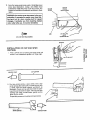
1, Finda 3/4-16 hex nut among the loose parts and
screw it onto headstock spindle until finger tight,
O
3/4-16 HEX NUT
_=
i i
i
ill
ill
i
CUP CENTER
CENTER POINT
/
D
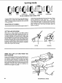
2. Find two center points, a spur center, and a cup
center among the loose parts. To insert a point into
a center, hold the center agatnst workbench as
i_Lustrated.Check and be sure that inside of opening at the end of center is clean. Place a point into
opening and using a small board, gently tap the
point into the center.
Repeat this process on the other point and center.
i
i
•
;i i,!; R,CENTERi:
i'! _ :i_Li_,:
CENTER
POINT
i
ii
i
i
.
illl i,iil,lll
3. Check and be sure that inside of headstock and
tailstock spindles are clean. Insert spur center into
headstock spindle and cup center into taitstock
spindle.
NOTE" Do not drive or hammer spur center and
oup center into spindles as removal may be difficult.
Use a soft hammer or block of wood and give them
a gentle tap.
1/4" DOWEL
\
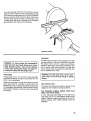
4. To remove spur center from spindle push motor
cover to left, hold the spindle pulley with one hand,
and using a wrench, turn the hex nut counterclockwise until center is ejected.
If this method doesn't eject spindle, remove motor
cover (see section covering "Mounting and Assembling Headstock"). Insert a 1/4" dowel rod or
brass rod through hole in spindle. Hold spur center
with one hand and tap dowel or rod with a hammer.
5, To remove cup center insert a 1/4" wood dowel or
brass rod through hole in taitstock as shown. Hold
center with one hand and tap dowel or rod with a
hammer.
\
21
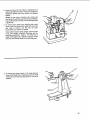
Lock the tailstock to the lathe bed by turning
tailstock lock clockwise until tight. Scribe a line on
the bed at right edge of headstock.
WARNING: Before using the iathe, test to make
sure headstock ls properly secured to lathe bed.
Failure to properly secure headstock to lathe bed
may al]ow headstock to move during use. This
could allow a spindle turning to come loose, fly
out, and cause injury to operator.
Rotate top of handwheel toward operator. This
applies pressure to the headstock as wood Estightened between centers.
As you continue to tighten handwheel, watch
headstock to see if it moves away from the line on
lathe bed. It should not move. If it does, go back
to section entitled "Mounting and Assembling
Headstock" and follow instructions to retighten
headstock to bed.
6. To be sure headstock is properly secured to lathe
bed, place a piece of wood between the centers
as irlustrated.
HANDWHEEL
/
WOOD
HEADSTOCK
/
\
TAILSTOCK
BED
22
INSTALLATION
SWITCH KEY
AND USE OF ON-OFF
WARNING: Don't connect power cord to an electrical outlet until your lathe is mounted in its
upright position. Failure to observe this warning
may cause motor relay to burn out.
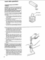
ON-OFF SWITCH
The On-Off Switch has a locking feature. THIS FEATURE tS INTENDED TO PREVENT UNAUTHORIZED
AND POSSIBLE HAZARDOUS USE BY CHILDREN
AND OTHERS.
1, Insert key into switch.
NOTE: Key is made of yellow plastic.
2. To turn Lathe ON., , INSERT your finger under
switch lever and pull END of switch out.
3, To turn Lathe OFF,,,
PUSH lever in,
WARNING: Never leave the lathe unattended until
it has come to a complete stop and you have
removed the switch key.
c
o
Do not cycle the motor switch on and off rapidly,
as this may cause the facepiate to loosen. In the
event this should ever occur, stand clear of the
faceplate until it has come to a complete stop,,.
retighten it,
ull
iii ii
iiii
n
ira|
I I
u
_.=
\
i
4. To lock switch in OFF position...
HOLD switch
IN with one hand, REMOVE key with other hand.
,,
,,,,,
WARNING: For your own safety, always lock the
switch "off". When lathe is not in use...remove
key and keep it in a safe place...also...in the
event of power failure (all of your lights go out)
turn switch off...Iock it and remove the key. This
will prevent the lathe from starting up again when
the power comes back on.
23
basic lathe operation
WARNING: To avoid Injury from unexpected starting, for your own safety, turn switch "off" and
remove plug from power source outlet before
making any adjustments or setups.
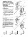
CHANGING
SPEEDS
The belt is shown positioned on smallest motor pulley
and largest spindle pulley. This causes lathe to operate
at 875 RPM.
To run the lathe faster -- say 1350 RPM. You must shift
the belt toward the motor.
1, Make sure power cord is removed from the outlet.
2. Release belt tension adjustment lever by pushing
it down and moving it to the center of the slot,
3, With motor cover slid back, turn spindle pulley
counterclockwise with your left hand while pushing
belt toward motor with your right hand.
4. Keep turning pulley while pushing on belt until it
"climbs" down onto the next smaller section of spindle pulley.
5. Now turn spindle puiley clockwise while continuing
to push belt toward motor until belt "climbs" up onto
next larger step of motor pulley.
To make the lathe go slower, the belt must be shifted
away from the motor.
1. Turn spindle pulley clockwise with your right hand
while pushing belt away from motor with your left
hand.
2, Keep turning pulley untit belt "climbs" down onto
next smaller step of motor pulley.
8. Now turn spindle pulley counterclockwise while stitl
pushing belt away from motor until belt "climbs" up
onto next larger step of spindle pulley.
NOTE; The belt must be fully engaged on the selected
pulley section before adjusting the bert tension lever.
Failure to do so could cause slipping of the belt and
early belt failure.
WARNING: Motor cover must be slid closed after
belt change is complete to prevent injury during
operation,
/k
MOTOR
875 RPM
24
J
MOTOR
I
MOTOR
t350 RPM
2250 RPM
MOTOR
3450 RPM
BELT TENSION
ADJUSTMENT
SLOT
1. Place belt tension adjustment
long slot,
lever in middle of
BELT TENSION
ADJUSTMENT LEVER"
2. Notice which lever support notch is immediately
below belt tension adjustment lever. Place lever in
this notch by pushing down and sideways on the
lever,
The lever is spring loaded so if belt slips during
operation, place lever in next lower notch.
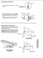
POSITIONING
OF THE TOOLREST
The tool rest should be positioned I/'8 inch above centerline of workpiece and 1/8 inch away from the section
on the workpiece to be cut.
WARNING: Failure to position the tool rest as
described can result in a turning tool being
thrown from your hand, causing severe injury.
1t8"
TOOL
SQUARE WORKPIECE
TOOLREST POSITIONED
AWAY FROM WORK
118"
e-
o
p,
.o--1/8"
p.
0.)
F:
u'j
---_,¢c
<:D ,._
.o_
O
r"
o
TOOLREST POSITIONED 1/8"
ABOVE CENTERLINE OF
WORKPIECE
ROUND WORKP]ECE
25
basic lathe operations
MOUNTING WOOD FOR SPINDLE
TURNING
WARNING:To avoid Injury from unexpected startIng, turn switch "off" and remove switch key
before mounting workpieoe in lathe.
We recommended that spindle turnings larger
than four Inches in diameter not be attempted.
DIAGONAL
LINES
SPUR CENTER
If you have not done a lot of wood turning, we suggest
you start by mounting a small spindle turning. Follow
these steps:
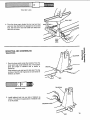
1, Carefully inspect and select a piece of wood 2" x
2" x 12"and always use wood free of checks, splits,
cracks or knots.
t16" DEEP CUT
2. Draw diagonal lines across each end of wood to
locate the center of each end.
3. On one end using a non-power handsaw, make a
saw cut approximately 1/16" deep on each diagonal
line. The spurs on the spur center will be placed
in these cuts,
4. The other end is for the cup center,Place point of
cup center on the wood where diagonal lines cross.
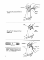
5. Drive cup center into wood. Use a wooden mallet
or a plastic hammer. If you don't have one, use a
steel hammer, but put a piece of wood on the end
of cup center to protect it. Remove the cup center.
6. Drive the spur center into other end of wood, Make
sure the sPurs are in the saw cuts, Remove spur
center,
7, Make sure the centers and the holes in the
headstock spindle and tailstockspindle are clean,
Insert spur center into headstock and cup center
into tailstock and tap them in lightly with a piece
of wood. Do not drive them in,
8. Put a drop of oil or wax on the wood where it
contactsthe cup center. This wilt lubricate the wood
while it is turning.
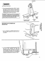
9. Place lhe wood between the centers and lock the
tailstock,
WARNING: To avoid Injury from thrown pieces,
be sure the spur center and cup center are firmly
seated against the workplece and that the tailstock is securely LockedIn place,
10. Move the cup center inlo the wood by turning
tailstock hand wheel, Make sure cup center and
spur center are "seated" into wood in holes made
in steps 5 and 6 above, Turn the wood by hand
while turning the hand wheel until the cup center
and spur center are tight against workpiece,
11, Lock the tailstock spindle by tightening the splndle
lock.
26
PLASTIC
HAMMER
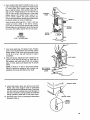
12. Adjust the tool rest approximately 1/8" away from
the corners of the wood and 1/8" above the center
line. Note the angled position of the tool rest base.
WARNING: For your own safety, after adjusting
• tool rest be sure and lock the tool rest holder,
e tool rest slide and the tool rest.
==-'2
d._ =._
Look at the speed chart. Notice that a 2" square
turning up to 18" long should run at 875 R.P.M. for
"roughing." Move the Poly-V-Belt on the pulleys to
the slowest speed as outlined under "Changing
Speeds" section.
When finish-turning any size wood, notice that the
recommended speed of the lathe is increased considerably above the rough-turning speed.
LINE
\
TOOL REST
However, if excessive vibration occurs at any speed
always shut the lathe off immediately and reduce
the speed until the vibration is not excessive.
During any spindle turning operation check all locks
frequently for tightness. Also frequently check the
fit of the cup center against the turning. Do not
allow the wearing away of wood to cause a loose fit.
WARNING: To avoid injury from thrown pieces,
turn workplece by hand to make sure it doesn't
hit any parts of the lathe. Always make sure the
workpiece is properly mounted and the lathe Is
set at the proper speed (RPM) before re-inserting
the switch key. Never spindle turn workpieces
longer than these specified in the chart for the
sizes shown. Never spindle turn workpieces
greater than 4" square.
FACEPLATE TURNING
WARNING: When doing faceplate turnings, always
follow instructions supplied with the faceplate for
mounting the workpiece to the faceplate. (for one
(1) possible exception--see "special note" to the
right) workpieces not properly and securely
attached to the faceplate may come loose during
operation, fly off, and hit the operator (fsceplates
are sold separately at SearHee
the list of recommended accessories for the correct part numbers.)
WOOD
FACEPLATE TURNING
e II=i[_];,I_I::(,-_,.tli={olll_l/l_[l'll
1z,
I0
5"
0"
] =_ _4"MAX
1
,"MAX
1
1
4"MAX
4"MAX
875
1350
1350
..... 2'250
1350 /
2250
2250
3450
SPINDLE TU RNING
1"
l
t2"
1350
3450
2"
3"
1
18"
27"
875
2250
2250
4"
J
36"
875
2250
i
SPECIAL NOTE: The instructions with your faceplate
may tell you to remove the 3/4-16 hex nut from the
spindle before installing your faoeplate. Instead of removing the 3/4-16 hex nut, tighten the faceplate up
against the nut on Modet 113.228360 Wood Lathe.
3/4-16 NUT
For information on how to do faceplate turning, refer to
the "Power Tool Know How" books available at your
Sears store, (See the list of recommended accessories
for the correct part number.)
Faceplates are attached to this wood lathe byscrewing
them onto the threaded section of headstock spindle and
up against the 3/4-16 hex nut as shown in the diagram,
Do not remove the 3/4-16 hex nut from the spindle when
mounting faceplates to the spindle on this model wood
lathe.
/
SPINDLE
FACEPLATE
27
turning tools
!
SKEW
GOUGE
PARTINGTOOL
THE SiX COMMONLY
A book entitled "Power Tool Know How Table Saw" is
available at your nearest Sears Retail Store or Catalog
Store. This book contains considerable data applicable
to the wood lathe.
SELECTION
mm
Im
OF CHISELS
Recommended chisels have handles approximately 10
SPEAR POINT
USED CHISEL
FLAT NOSE
ROUND NOSE
TYPES
inches long to provide plenty of grip and leverage. Sharp
tools are essential for clean, safe work..,
buy tools
that will take and hold clear edges. There are six com.
monly used chisel types. The gouge skew and parting
tool are used for cutting under the surface of lhe workpiece. The flat nose, round nose and spear point are
used for scraping.
CUTTING AND SCRAPING
When doing a cutting operation, the chisel is held at
an angle so the sharp edge actually cuts below the
revolving workpiece surface to peel off shavings. To do
a scraping operation, the chisel is held at a right angle
to the workpiece and removes fine particles instead of
shavings. Many operations require that cutting chisels
be used for scraping, but scraping chisels should never
be used for cutting. When cutting, materiat is removed
faster than when scraping and produces a smoother
finish which requires less sanding.
CUTTING
WHEN YOU CAN
MUST SCRAPE
SCRAPING
CUT AND WHEN YOU
If yoL_are removing wood from the circumference of a
workpiece (for example, turning down the outer surface
of a cylinder or the inner wall of a hollow round box)
you may use either a cutting or a scraping action. This
is true because the granular structure of the wood will
allow easy removal of wood at the circumference of the
workpiece in much the same way as a peeling is removed from an apple or a potato,
28
CIRCUMFERENCETURNING
If you are removing wood from the diameter of a workpiece (as when turning the face of a faceplate turning)
you must use a scraping action only.This is true because
you are removing wood across the grain. Wood does
not peel easily across the grain, and attempts to use
a cutting action will result in damage to the workpiece
and throwing of the chisel by the workpiece,
DIAMETER TURNING
iii
i
,11,ii
THE SKEW
WARNING: To avoid having the woodworking
chisel torn from your hand, always work from a
larger diameter toward a more narrow diameter
on the wood turning and always do rough circumference cuffing with the gouge chisel.
THE GOUGE
Threegouges, the 1/4-, 1/2- and 3/4-in, sizes, are ample
for general homeshop turning; but other sizes from 1/8to 2-in. can be purchased.
Always use the gouge for rough circumference turning
of raw stock down to a cylinder of working size. It is
the best tool to use for rapid cutting away of large areas
of the workpiece. With practice, it can be used for cutting
coves and the shaping of long cuts and is also useful
for scraping.
The skew should be used only by operators who have
become proficient in the use of all other turning tools,
Two skews, the 112- and 1-in. sizes, are all that are
needed for general use, Other sizes are available. This
tool is used to make finish cuts and to cut vees and
beads. Properly used, it produces the best finish that
can be obtained with a chisel.
WARNING: To avoid injury from a thrown workpiece, never cut all the way through a spindle
turning.
THE PARTING TOOL
The parting tool has just one primary purpose: to cut
straight into the workpiece as deep as desired.
THE SCRAPING CHISELS (SPEAR POINT, FLAT
NOSE, AND ROUND NOSE)
A 1/2-in, wide spear point chisel, a 1/2-in. wide round
nose chisel, and a 1-in, wide flatnose chisel are very
useful for diameter scraping operations and for circumference scraping, when cutting methods cannot be
employed,
29
HOLDING THE WOODWORKING
CHISEL
WORK PIECE
In handling alt turning tools, the handle hand takes a
natural position, being nearer or farther from the end
of the handle depending on the amount of leverage
required. The position of the tool rest hand should be
as illuslrated with turning tool held firmly against the
tool rest and fingers and thumb wrapped around the
turning tool on the opposite side of the tool rest, away
from the rotating workpiece.
TOOL
REST
TOOL REST
WARNING: To avoid Injury from a thrown turning
tool, keep firm hand grip on the tool by wrapping
fingers and thumb around tool. Use both hands
spaced apart for proper leverage and control.
Keep your weight balanced on your feet. Do not rest
your weight on the turning tool or tool rest. Avoid awkward hand positions where a sudden slip could cause
a hand Io move into the workpiece.
WOODCUTTING
CHISEL
HANDLE
HAND
maintenance
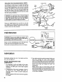
WARNING: For your own safety, turn switch "off"
and remove plug from power source outlet before
maintaining or lubr]catlng your lathe.
I_..--WlR
Apply a coat of automobile-type wax to the lathe bed
to help the tool rest and tailstock move freely.
HITE-'I
II
I
E NUT
._._,_.h_
Have power cord replaced if it becomes wornor frayed.
tn
[ BLACK
S_ITC-L_H
lubrication
Periodically lubricate the ram in the tailstock with No.
20 or No. 30 engine oil.
MOTOR MAINTENANCE
LUBRICATION
AND
1. The bearings, in both end shields of the motor,
have been lubricated at the factory with correct
lubricant. No other part of the motor requires
lubrication.
2, If disassembly of the motor is necessary, it should
be returned to your nearest Sears retail or
mail-order store in order to prevent voiding the
guarantee,
NOTE: The speed of this motor cannot be regulated
or changed,
3O
3_
Every effort should be made to prevent foreign material from entering the motor. When operated
under conditions likely to permit accumulations of
dust, dirt, or waste within the motor, a visual inspection should be made at frequent intervals. Accumulations of dry dust can usually be blown out
successfully.
NOTE: Motors used on wood-working tools are
particularly susceptible to the accumulation of sawdust and wood chips and should be blown out or
"vacuumed" frequently to prevent interference with
normal motor ventilation.
Sears recommends the following
ITEM
Work Bench ......................
Drill Chuck 1/2" Capacity with
No, 1 M,T, Shank ................
Screw Center with No. 1 M.T. Shank .,
Batl Bearing Center with
No. 1 M,T, Shank ................
60oCenter with No. 1 M,T, Shank .....
Face Plate, 4" Diao with 3/4"-16 Thread
9 Holes ............................
Copy Crafter .........................
Sears may recommend other accessories
the manual.
CAT. NO
See Catalog
See Catalog
See Catalog
See Catalog
See Catalog
9-2489
9-24917
not listed in
accessories
ITEM
CAT. NO.
Turning Tools .....................
See Catalog
Draw Bolt with I/4"-20 Threads .......
See Catalog
Power Tool Know-How Handbook ........
9-29114
Bowl Turning Tool Rest ................
9-24903
Face Plate 6" with 3/4"-16 Thread
6 holes ...........................
9-24904
Face Plate 4" dia. with 3/4"-16 Thread
Cast Iron, 6 holes ................
See Catalog
Do not use any other accessory unless you have received and read complete instructions for its use,
See your nearest Sears store for other accessories.
trouble shooting
WARNING: For your own safety, turn switch "off" and remove plug
from power source outlet before trouble shooting.
TROUBLE
SHOOTING
TROUBLE
PROBABLE CAUSE
Motor will not run.
1. Defective On-Off switch.
Defective switch cord.
Defective switch box receptacle.
,
Burned out motor.
,
Lathe slows down
when turning
.
Blown fuse or
tripped circuitbreaker
Poly-V-Belt slipping,
2. Pulley Lock screws loose.
Excessive noise
CHART
REMEDY
1. Replace defective parts before usingLathe
again.
2. Consult Sears Service. Any attemptto repairthis
motor may create a HAZARD unless repair is
done by a qualified service technician. Repair
service is available at your nearest Sears store.
3. Replace fuse or reset circuit breaker.
1. Adjust belt tension, see Assembly Section.
2. Tighten lock screws. See Section "Mounling
and Assembling Headstock."
Headstock loose
on bed,
Setscrew not tight.
1, Tighten setscrew, See Section, "Mounting
and Assembling Headstock."
Wood burns at
tailstock end.
Cup center too tight or not
lubricated.
1. Back off tailstock ram and lubricate
cup center. See Basic Lathe Operation
Section, "Spindle Turning."
31
trouble shooting
TROUBLE
SHOOTING
-- MOTOR
NOTE: Motors used on wood-working tools are particularly susceptible to the accumulation
of sawdust and wood chips and should be blown out or "vacuumed" frequently to prevent
interference with normal motor ventilation and proper operation of the centrifugally-operated
starting switch.
TROUBLE
Excessive noise.
1. Motor,
Motor fails to develoP ........
1. Circuit overloaded witt7 ....
full power. NOTE: LOW
lights, appliances and
other motors.
VOLTAGE: (Power output of motor decreases
rapidly with decrease in 2. Undersize wires or circuit
too long.
voltage at motor terminals. For example, a re3. General overloading of
duction of 10% in voltpower company
age causes a reducfacilities,
tion of 19% in maximum
poweroutputof which
the motor is capable
and a reduction of 20%
in voltage causes a reduction of 36% in maximum power output,)
Motor starts slowly
or fails to come up
to full speed.
Motor overheats.
Motor stalls
(resulting in blown)
fusesor tripped
circuit breakers).
Frequent
;penirig
of
fuses or circuit
breakers.
Tool rest will
not slide along
fu]l length of bed.
32
REMEDY
PROBABLE CAUSE
1. Have motor checked by qualified service
technician. Repair service is available at
your nearest Sears store.
1, Do not use other appliances or motors on
same circuit when using the lathe.
2. Increase wire sizes, or reduce length of wiring.
See "Motor Specifications and Electrical
Requirements" section.
3. Request a voltage check from the power
company.
1. Low voliage will not
trip relay,
1, Request voltage check from the power company.
2. Windings burned out
oropen.
2. Have motor repaired or replaced.
3, Starting motorwhile headstock is not in normal
operating position.
,
4. Starting relay not
operating,
,
Place headstock in normal operating position
and restart motor. If motor fails to start go to
probable cause Number 4.
Have relay replaced.
1. Motor overloaded.
1. TakeShallower cuts l................
2. Impropercooling. (Air
circulation restricted
through motor due to
sawdust, accumulating
inside of motor.)
2. Clean out sawdust to provide normal air
circulation through motor.
See Maintenance and Lubrication" section,
1. Voltage too low to permit
motor to reach operating
speed.
']",' Request voltage check from the power company.
2, Fusesorcircuit breakers
do riot have sufficient capacity,
2, Install proper size fuses or circuit breakers,
1, Motor overloaded,
1. Take shallowercuts.
2, Fusesorcircuit breakers
do not have sufficient capacity.
2. Installproper size fuses or circuit breakers.
1, Bed sections are not
straight and level
with each other.
1. Complete instructions in section entitled
"Mounting You r Wood Lathe to Workbench"
NOTES
33
\
\
\
\
\
\
/
t
t
/
\
\
\
\
$
s_
_A,_J,5
LlSl
Always
Key
No.
Part
No.
FUH _HAF
_ /tAN lz"Wuuu
MODEL
NO_13.228360
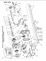
order by Part Number--Not
Description
by Key Number
Key
No.
Pa_
No.
i
1
2
3
4
5
6
7
8
9
10
11
12
13
14
15
16
17
18
19
20
21
22
23
24
25
507816
816757
816775
816751
STD580101
STD502503
816575
38884
805645-5
816868
STD580275
816565
816989
816569
56619
816586
STD551037
816992
70016
816570
816578
816581
816564
816991
141594-42
26
28
29
3O
31
816990
816567
816990-2
816579
STD522515
32
33
34
35
36
STD522510
816552
9414920
STD551125
STD541025
Cover-Motor w/Labels
Housing-Fan
Wheel-Turbine
oMotor
* Key-3/16 Sq. x 3/8
* Screw-Soc. Set 1/4-20 x 3/8
Pulley-Motor
Ring-Retaining
Ring Retaining Bowed
Bearing-Bail
*Ring-Retaining 3/4
Spindle
Nut-Hex 3/4-16
Center-Spur
Center-Point
Holder-Toot Rest
*Washer-.380 x 1-9/64 x 7/64
Clamp-Bolt
Rest-12"Toof
Center-Cup
Handwheel
Stock-Tail
Spindle-Tail Stock
Clamp-Bolt
Screw-Hex Soc. HD. Cap
10-32x 1
Clamp-Bolt
Slide-Tool Rest
Clamp-Bolt
Bed-Machined
*Screw-Hex. HD.
1/4-20 x 1 1/2
*Screw-Hex. 1/4-20 x 1 1/2
Bracket-Bed Center Mtg.
Washer 17/64 x 5/8 x 1/16
*Lockwasher-1i4
*Nut-Hex 1/4
LAIHE
37
38
941492O
STD522525
39
40
41
42
43
44
45
46
47
48
STD510803
STD551210
802392-41
816439
STD510607
STD551206
816831
507817
STD610603
60227
49
50
51
52
53
54
55
56
57
58
59
60
61
62
63
64
65
--
816573-1
69164
816560
816825
815863
816566
816945
817134-4
817157
803709
802955-7
816946
816758
816759
816572
STD503105
816591
SP5110
507635
507743
"I}
Description
me
ii
Washer 17/64 x 5/8 x 1/16
* Screw-Hex HD.
1/4-20x 2-1/2
*Screw-Pan HD. #10-32 x 3/8
*Lockwasher #10
Spacer
Belt-PolyV"J" 14
* Screw-Pan HD. 6-32 x 3/4
* Lockwasher Ext. #6
Knob-Tension Lever
Housing-w/Labels
*Screw-Ty. B #6 x 3/8
Screw-Soc. Set
5/t6-18 x 1 1/4
Cord w!Plug
Relief-Strain
Lead-Jumper
Screw-Motor Pivot
Key-Switch
Switch-Locking
Box-Switch R.H.
Tie Cable
eRelay
Connector-Wire
*Nut-Push 1/4
Box-Switch L.H.
Lever-Tension
Rod-Motor Pivot
Pulley-Spindle
* Screw Cone Pt. 5/16-18 x t/2
Head-Stock
Owner's Manual
(Not Illustrated)
Bag of Loose Parts
(Not Illustrated)
Bag of Loose Parts
(Not Illustrated)
* Standard Hardware Item -- May Be Purchased Locally.
* if this part is removed, discard and replace with a new Push Nut.
O1
e Relay must accompany motor when motor is returned for service. Any attempt to repair this motor may create
a hazard unless repair is done by a qualified service technician. Repair service is available at your nearest
Sears Store.
"o
U}
_A/RS
12-1NCH
WOOD LATHE
owner's
manual
SERVICE
Now that you have purchased
your 12-inch Wood Lathe
should a need ever exist for repair pads or service, simply
contact any Sears Service Center and most Sears, Roebuck
and Co. stores. Be sure to provide al! pertinent facts when
you call or visit.
MODEL NO.
113.228360
The model number of your 12-Inch Wood Lathe wilt be found
on a plate on the backside of the headstock.
WOOD LATHE
HOW TO ORDER
REPAIRPARTS
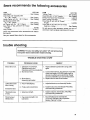
WHEN ORDERING REPAIRPARTS,ALWAYS GiVE THE FOLLOWING
INFORMATION:
IF YOU NEED REPAIR
SERVICE OR PARTS:
PARTNUMBER
PARTDESCRIPTION
MODEL NUMBER
113.228360
NAME OF ITEM
12-INCH WOOD LATHE
All parts listed may be ordered from any Sears Service Center
and most Sears stores. If the parts you need are not stocked
locally, your order will be electronically
transmitted
to a
Sears Repair Parts Distribution Center for handling.
For Repair Service, Cal!
this Toll Free Number:
1-800-4-REPAIR
(1.800-473-7247)
For Replacement Parts
Information and Ordering,
Call this Toll Free Number:
1-800-FON-PART
(1-800-366-7278)
j
J
Sears, Roebuck and Co., Hoffman Estates, IL 60179 U.S.A,
Part No, SP5110
Form
No, SP5110-4
Printed
in U,S,A, 5/95