1
, ,u
Sears I
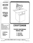
owners
manual
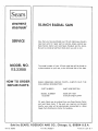
SERVICE
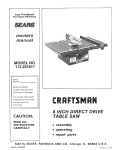
tO-INCH
RADIAL SAW
Now that you have purchased your lO-inch
radial saw, should a
need ever exist for repair parts or service, simply contact any
Sears Service Center and most Sears, Roebuck and Co. stores_
Be sure to provide all pertinent
MODEL NO.
i!3.23100
HOW TO ORDER
REPAIR
PARTS
facts when you call or visit_
The model number of your tO-inch radial saw will be found on
a p{ate attached to your saw, at the left-hand side of the base.
WHEN ORDERING
REPAIR
FOLLOWING
INFORMATION:
PARTS,
ALWAYS
GIVE
PART NUMBER
PART DESCRIPTION
MODEL NUMBER
1 ! 323100
NAME OF ITEM
IO-INCH RADIAL
THE
SAW
Al! parts listed may be ordered from any Sears Service Center
, and most Sears stores. If the parts you need are not stocked
"locally, your order will be electronically
transmitted to a Sears
Repair Parts Distribution
Sold
by SEARS,
ROEBUCK
AND
CO.,
Center for handling.
Chicago,
IL. 60684
U.S.A.
additionaR
CAU_'ION:
Always
removir,_) the guard,
set.up.
Jr
perforr_ing
safety
instructions
disconnect
the
power cord before
changing the cutting tool, changing the
making
adjustments°
Shut
off
layout work on the saw table..
motor
Assembly
UNTIL
BEEN
and alignment°
11. Examination
and operating
familiarity
with
ON-OFF
switch,
e_evation
control,
yoke index and lock, bevel
index
and lock,
carriage
lock,
guard
clamp
screw,
spreader
and antikickback
device, and miter index and
Iock_
IhL Review and understanding
of all Safety
Operating
Procedures thru-out
manual
Instructions
and
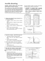
'1o Set carriage
Bolt
the
slide during
3o
Mount
lock before
saw to
the
normal
moving
floor
the saw..
if it tends
to
slip,
walk,
or
operation.
the saw so the table
-
is approximately
-
slopes slightly
downward
to the rear so the carriage
will not roll forward
due to gravity
MINIMIZE
Most
setup
ACCIDENT
39"
above the floor;
POTENTIAL
accidents
are caused by
and operating
instructions:
FAILURE
TO
FOLLOW
(A) GENERAL
-Avoid
could
awkward
hand positions,
where a sudden slip
cause a hand to move into a sawbiade or other
cutting
toot
Never reach in back of or around the
cutting
tool
with
either
hand to hold
down
the
workpiece,
or for any other
reason; DO NOT place
fingers
or hands in the path
Never
saw,
dado,
mold,
of the sawblade
or rabbet
unless
the
proper
guard is installed and set up as instructed.
-NOTE
THE
FOLLOWING
DANGER
LABELS
WHICH APPEAR
ON THE FRONT
OF THE YOKE
AND GUARD:
DANGER
DANGER
TO
NOT
O0
FEED
MATERIAL
JNT0
CUTTrNG
TOOL
THIS
-if
DO
NOT
ALLOW
FAMILIARITY
FROM
FREQUENT
USE OF
YOUR
BECOME
COMMONPLACE°
ALWAYS
THAT
A CARELESS
FRACTION
OF
IS SUFFICIENT
TO INFLICT
SEVERE
-Before
starting
work,
verify
that no play exists
between
the column
& column
support,
or in the
carriage, and that arm, yoke, and bevel locks/clamps
are tight.
-A
large proportion
of saw accidents
is caused by use
of the wrong type blade, dull, badly set, improperly
sharpened
cutting
tools, by gum or resin adhering to
cutting tools, and by sawblade misatignment
with the
fence.
Such conditions
can cause the material
to
(stall
the saw) or "KICKBACK"
A
occurs
when
a part or all of the
is thrown
back
violently
toward
the
NEVER
ATTEMPT
TO
FREE
A
SAW
BLADE
WITHOUT
FIRST
TURNING
THE SAW
"OFF".
If the sawbtade
is
stalled
or
jammed,
shut
saw "'OFF",
remove
workpiece,
and check sawblade
squareness to table
surface and to the fence, and check for heel.. Adjust
as indicated,
--CAUTION:
DO NOT cycle the motor
switch "ON"
and "OFF"
rapidly,
as this might cause the sawblade
to loosen. In the event this should ever occur, allow
the saw blade to come to a complete
stop and
re-tighten
the arbor nut normally,
not excessively.r
-Do
not leave a long board
{or other
workpiece)
unsupported
so the spring of the board causes it to
shift
on the tamer Provide
proper
support
for the
workpiece,
based
on its size and
the type
of
operation
to be performed,.
Hold the work firmly
against the fence and down against the tabte surface.
-Never
use a length
stop
on the free end of the
workplece
when crosscutting
Never hang onto or
touch
the free end of workpiece
when crosscutting,
or a free piece that is cut off when ripping
while
power is "ON"
and/or
the saw Made is rotating
(n
short, the cut-off
piece in any "thru-sawing"
(cutting
completely
thru the workpiece)
operation
must never
be confined
- it must be aIlowed
to move laterally
- Make
when
power
sure your fingers do not contact
the terminals
installing or removing the plug to or from a iive
source
AVOtD
_NJURY
-Always
maintain
control
of
NOT "let go" the workpiece
has come to a stop_
(GAINED
SAW) TO
REMEMBER
A SECOND
INJURY.
stick,
jam
"KICKBACK"
workpiece
operator
STALLED
I tSTALLATION
.2,.
-WARNING:
before
WARNING:
DO NOT CONNECT
POWER
CORD
THE
FOLLOWING
STEPS
HAVE
SAqP_SFACTORILY
COMPLETED;
I.
for radiaU saws
FROM
END
the workpiece
- DO
until the cutting
toot
any part of this radial saw is missing or should
break,
bend or fail in any way, or any electrical
component
fail to perform
properly,
shut off power
switch,
remove cord from power supply and replace
damaged, missing and/or failed parts before resuming
operation
--IF
YOUR
SAW MAKES
AN UNFAMILIAR
NOISE
OR
IF
IT
VIBRATES
EXCESSIVELY
CEASE
OPERATING
IMMEDIATELY
UNTIL
THE
SOURCE
HAS
BEEN
LOCATED
AND
THE
PROBLEM
CORRECTED.
- Never climb
on the saw, or climb near the saw when
power
in "ON"..
Never leave the saw with
power
"ON",
or before
the cutting
complete
stop
Lock the motor
the key when leaving the saw
tool has come
switch and put
to a
away
- Do not use any blade or other cutting
tool marked
for an operating
speed lower than 3450 RPM. Never
use a cutting
tool
larger
in diameter
than the
diameter
for
which
the
saw was designed,
For
greatest safety and efficiency
when ripping,
use the
maximum
diameter
blade
for
which
the saw is
designed, since under
nearest the blade,.
- Never turn your
or work surface
these conditions
the spreader
saw "ON"
before clearing the table
of all objects (tools, scraps of wood,
etc.)
except
the workpiece
and related
support
devices for the operation
planned-Never
perform
is
any
operation
"FREE
HAND"
feed
or
This
term means feeding the sawblade into the workpiece
(crosscutting)
or
feeding
the sawblade
or other
cutting
tool
(ripping)
without
using the fence to
additional
safety
instructions
for
support
or guide the workplace,
to prevent rotating
or twisting
of the workpiece
during
the operation
Never "RIP"
in the crosscut position.
Never make a
miter cut with the arm in the 90 ° crosscut position.
slippery,
the
kick back
and be propelled
-The
sawblade,
removed
from
dado,
the
toward
t3,
you
or other cutting
tool must be
saw
arbor
before
using
the
accessory shaft (rear end of the saw motor).
NEVER
operate the saw with cutting tools (including
sanding
accessories)
insta!led on both ends of the saw arbor
(B) RIPPING
1
Feed force when ripping
must always
be applied
BETWEEN
THE SAW BLADE
AND THE FENCE
use a "PUSH STICK"
for narrow
or short work
2
Whenever
possible,
use the in-rip
position
- this
provides
minimum
obstruction
for feeding by hand
or push stick as appropriate.
3,
Do
not
release
complete
rear (outfeed
4
the
workplace
before
operation
is
6
CAUTION:
antikickback
7,
14,.
Make sure by trial before starting
the cut that the
antikickback
pawls will stop a kickback
once it has
started,
Points of pawls must be SHARP
Replace
when points are dul! or rounded
Use a push stick
when
ripping
short (under
t2
inches) or narrow
(under 6 inches wide) workpieces.
Never
reposition
with power "ON".
the
Guard
NEVER
stacking
cut
more
workpieces
than
one
1.
at
a time
pull
the workpiece
Position the saw so neither
you, a helper, or a casual
observer
is forced
to stand
in
line
with
the
sawblade,
ALWAYS
RETURN
THE
CARRIAGE
TO THE
FULL
REARWARD
POSITION
AT CONCLUSION
OF EACH CROSSCUT
TYPE OPERATION.r
Never
2
Place guard
antlkickback
or workplace,
3.
NEVER
gang crosscut
- lining up more than one
workpiece
in front of the fence - stacked vertically,
or horizontally
outward
on the table - and then
pulling
saw thru:
the blade could
pick up one or
more pieces and cause a binding
or loss of control
and possible injury,
4.
Do
by
not
in horizontal
position
pawls to just clear the top
whichever
is higher.
position
the
Arm
and adjust
of the fence
so the operation
toot
you
to
are
extend
(D) ACCESSORIES
another
edge of
piece being cut), even if of the same thickness.
Feed
each workpiece
individually
thru the sawblade, and
completely
beyond the sawblade, before ripping the
next workpiece
Use push stick if the rip cut is less
than 6" wide.
-
a
When sawing 1/4" or thinner
materials,
follow
all
normal ripping
procedures
except set sawblade into
table
top at least 1/8"
This will
minimize
the
tendency
for the sawblade to climb upon top of the
workpiece,
and possibly cause an accident
DO NOT
let go of or stop feeding the workplace
between the
blade and fence until you have pushed it completely
past
the
antikickback
pawls.,
Otherwise
the
workplace
could get into the back of the sawblade
and be thrown
violently
from
the saw in the
direction
opposite
to the feed direction.,
This is the
same action that would occur if the instructions
oF
performing
permits
the cutting
beyond the edges of the Table..
vertically.
10o NEVER
feed a workpiece
thru the saw with
piece (butting
second piece against trailing
11.. DO NOT
s,'op
remove your hand from the Yoke Handle unless the
carriage
is in this position..
Otherwise
the cutting
too!
may
climb
up on the workplace
and be
propelled
toward you,
to just clear the
the antikickback
piece
not
(C) CROSSCUTTING
or
workplece
being cut. "HEEL"
can be avoided by
maintaining
the sawbtade
exactly
parallel to the
fence. (see "DANGER"
warning on guard) - it can
be avoided by maintaining
parallelism
of sawbfade
to fence, feeding into the sawbiade from the nose of
the guard only, and by utilizing
the spreader_
9..
may
wood that has a twisted
grain or is twisted or bowed - it may rock on the
table and/or
pinch the sawblade,.
If bowed across
the width,
place concave
side down against the
table,
A "t<'ICKBACK"
occurs
during
a rip-type
operation.
It can occur when the workpiece
closes
in on the rear
(outfeed
side) of the sawblade
Position
the nose of the guard
workpiece,
and position/adjust
and spreader devices as instructed.
pawls
15o Use extra care when ripping
(pinching),
binds
between
the
fence
and
the
sawblade (heel), or is grabbed by the sawblade teeth
(wrong-way
feed) at the outfeed side. "PINCHING"
is generally
avoided
by utilization
of the spreader,
and a sharp sawblade of the corrective
type for the
8
antikickback
the DANGER
warning on the guard is aborted.
Dc
not stand, or permit
anyone
else to stand, in line
with
the path of a workplace
that may be thrown
from the saw in this manner
push the workplace
all the way past the
or exit) of the sawbtade
5,
saws
Therefore,
rip with the finished
side down mext to
the table) and be especially
attentive
to fo lowing
proper set-up and cutting
procedures,
Do not stand,
or permit
anyone
else to stand,
in line with
a
potential
kickback.,
-- Never lower a revolving
cutting tool into the table or
a workpiece
without
first locking
the Carriage
Lock
Knob. Release the knob only after grasping the Yoke
Handle.
Otherwise
the cutting
tool
may grab the
workpiece
radial
thru
1.,
Use only
Accessories
2.
Never operate this saw when equipped
with a dado
head or molding
head unless the molding
head
guard is installed
see listing
of recommended
accessories° The only exception
is when "top-side"
dadoing or molding,
when the sawbtade guard must
be used., See detailed
instructions
that accompany
the dado head, molding
head, and molding
head
guard,
the sawblade
position
your body at the nose (in-feed)
side of
the guard: start and complete
the cut from that
same side, This will require added table support
for long pieces
&
The
use
recommended
Section in this
of
abrasive
or
accessories
manual
cut-off
as
wheels,
listed
or
in
wire
wheels, can be dangerous
and is not recommended,
(Abrasive
or cut-off
wheels are used to saw many
different
materials
including
metals,
stone,
and
gtass,)
12, Plastic
and
composition
(like
styrene
and
hardboard)
materials
may be cut on your
saw..
However,
since these are usually
quite
hard and
4
WEAR
YOUR
The operation
of any power
tool can result in foreign
objects
being thrown
into the eyes, which
can result in
severe eye damage. Always
wear safety goggles complying
with
ANSI Z87 t (shown on Package) before commencing
power tool operation
Safety Goggles are available at Sears
retail or catalog stores
unpacking
and
assembRy
CONTENTS
General Safety Instructions for Power Tools .............
Additional
Safety Instructions
for Radial Saws ........
Guarantee
....................................
Unpacking and Assembly
..........................
Alignment
Procedure
...................................
Operating Controls
..............................
2
3
5
5
8
14
Basic Saw Operations
Electrical
Connections
...................................
..............................
t7
21
Trouble--Shooting
................................
Maintenance
and Lubrication ...........................
Recommended
Accessories
................................
23
27
28
Repair
29
Parts
......................................
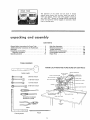
TOOLS NEEDED
KNOW LOCATIONS
Rubber
mallet
3!8*inch
7t16qnch
lt2-inch
@
9/16-inch
Screwdriver
Screwdriver
Framing
square
wrench
wrench
wrench
wrench
(medium)
(small)
Pencil
AND
FUNCTIONS
OF CONTROLS
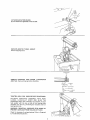
unpacking
UNPACKING
and assembny
AND PREASSEMBLY
WARNING:
DO NOT CONNECT THE POWER CORD TO
A SOURCE OF POWER. THIS CORD MUST REMAIN
UNPLUGGED
WHENEVER
YOU ARE WORKING ON
TH E SAW.
4
5
Your Craftsman
1e-inch Radial Saw is shipped complete
in
one carton.
Cabinet
and goose neck tamp are optional
accesscories.
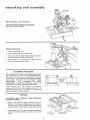
Unpacking
and Checking
Contents
Separate all "loose"
parts from packaging materials
and
check each item with "Table
of Loose Parts" to make
sure all
items are accounted
packing
material°
for,
before
discarding
any
If any parts are missing, do not attempt
to assemble the
radial saw, plug in the power cord, or turn the switch
on until the missing parts are obtained
and are installed
correctly.
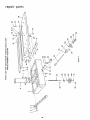
Key No.
(Fig, t)
1
2
3
4
5
6
7
8
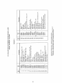
Table of LooseParts
Qtyo
BasicSaw assembly ......................
Reartable ................................
Table spacer .............................
Rip fence ..............................
Front table .............................
Channel,Table Mtg.......................
"Owner's Manual" . ......................
Loose PartsCarton (containing the
following items):
Hex-"L" Wrench, I/8"o ....................
Hex-"L" Wrench, t/4 ....................
Hex-"L" Wrench, 3/16 ....................
Elevation crankassembly .................
Swivel LatchPin Knob ..................
Switch key .............................
Arbor Wrench ..........................
Table clamp .............................
1
I
1
t
I
2
1
1
t
1
1
t
2
1
2
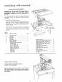
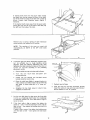
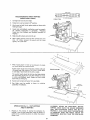
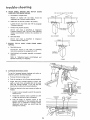
REMOVE SKIDS FROM BASE
MOUNT SAW TO CRAFTSMAN
LEG SET, OR FLAT BENCH
BASE OR
Make sure elevation crank is free to rotate. The saw must be
bolted down° Position your entire saw (or saw bench) to
slope slightly rearward, so the carriage will not roll forward
due to gravity°
Rip-scaleindicator ........................
Twin nut (for attaching rip-scaleindicator) .,
Machinescrew,pan÷hal.r,
!/4-20 x t" o......
Washer,steel(flat), 17/64 x 5/8 x 1/32". ....
Machinescrew,pamhd, 6-32 x 7/16" . ......
Shaft wrench .............................
Screw, He× Hd., 5/16-I8 x t/2 ...........
Lockwasher, 5/16 ......................
Washer,Flat, 11/32 x 7/8 x 1/t6 ...........
Nut - "T". ............................
Set Screw, Cup,Pt .......................
Screw, PanHead, 1/4-20 x lq14 .............
Nut, Speed
...........
...................
2
2
6
7
4
t
4
4
4
1
1
1
6
ATTACHELEVATION
CRANK,
Be sure setscrew is tightened on flat of shaft.
ELEVATE ARM TO ITS MAX_ HEIGHT,
Remove shipping btock,
ELEVATION
TURN CLOCKWIS_
INF O_MAI
_0 N
TAG
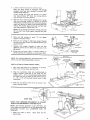
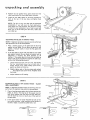
REMOVE
CARRIAGE
STOP SCREW, LOCKWASHER
AND TAG. Read warning tag before discarding
_,_
LOC KWASH[_
/SlOP
SCrEw
HE_(
TIGHTEN
ARM
LOCK
KNOB BEFORE
PROCEEDING.
HOLDING
CARRIAGE
ASSEMBLY
WITH BOTH
HANDS,
CAREFULLY
START
AND SLIDE THE
CARRIAGE ONTO THE TRACKS. The assembly must be
held parallel with the arm so that all four bearings slide
smoothly onto the arm, preventing any excessive strain on
bearings and track°
WARNING:
REINSTALL
CARRIAGE
STOP SCREW TO
PREVENT CARRIAGE FROM ROLLING OFF ARM,
Check for looseness of carriage bearings. Refer to Paragraph
8, Trouble Shooting Sectiom
[
WRENCH
SUPPLIED
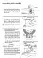
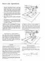
unpacking
assernbWy
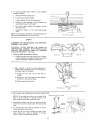
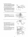
SWIVEL LATCH
_NOB
INSTALL
SWIVEL
LATCH PIN KNOB.
REMOVE SHIPPING SCREWS AND DISCARD°
Use of pliers may be necessary,
REMOVE
OF MOTOR
SHOWING
LOCATION
OF TWO
SHIPPING SCREWS
SAW BLADE.
1.
Tighten
carriage
lock
2.
Loosen
guard
3,
Motor
sh_ft has left hand threads,
Hold
and rotate arbor wrench down (clockwise),
4o
Remove
shaft
nut, outer collar, saw blade,
collar. Set aside and out of the way,
clamp
knob,
screw,
ALIGNMENT
remove
guard,
shaft wrench
and
inner
PROCEDURE
The fotlowing
SIX STEP alignment
procedure will bring out
the accuracy
which
is built
in every CRAFTSMAN
tool,
The secret for best results is in knowing
how to set up the
tool and keep it in good alignment.
BE SURE TO CHECK
AND
ALIGN
THE
SAW
tN THE
ORDER
GIVEN,
STEP-BY-STEP.
THE
ACCURACY
OF
EACH
ADJUSTMENT
IS ALWAYS
DEPENDENT
UPON
THE
ACCURACY
OF THE PRECEDING
ADJUSTMENT.
After
following
the
6
step
assembly
procedure
and the Basic Saw operation
Trouble
Shooting
section
if any difficulty
when performing
any sawing operation
and
alignment
section
refer to
is experienced
STEP ONE
ATTACHING
AND
LEVELING
SUPPORT CHANNELS.
Attach
5/16-18
Position
permit
2,
TABLE
MOUNTING
table
mounting
support
channels
with
four
x 1/2 screws, Iockwashers
and fiat washers.
screws in center of channel slots, finger tight to
channels
to "slip"
against
the base when
leveling.
Loosen bevel lock knob, lift up on latch pin handle and
rotate
the motor
to position
saw blade, end of shaft
down.
M AND
t
I I
kL;
/
TABLE
sH°uL°BE
l
P, LL,L
\-
I
I
U
I1
'........................
3. Loosen
armlockknobuntilarmisfreetomove,
Note:Forsafetyreasons
in accordance
with theUL
standard,
stopshavebeenprovided
to prevent360 °
rotation
of the radial
arm.
Loosen
carriage
loci< knob
and position
arm against
stop (approximately
50 ° Miter)
and carriage directly
over the center of left hand channel.
4.
Slide the arbor wrench handle
between
end of motor
shaft
and mounting
channel
to achieve an accurate
measurement.
Carefully
lower the motor with elevation
crank until
the end of shaft
wrench.
The wrench
should
only slight resistance., Tighten
is just touching
the arbor
slide back and forth with
screw "A".
NOTE:
Do not change this elevatlon
setting
left and right hand table support
channels
adjusted
5,
Move
arm and carriage
to
support
in the same manner
6.
Move arm and carriage
to right hand support
channel
and level in the same manner you adjusted the left hand
support channel
7o
Recheck
both
tightening
adjustment.
support
screws
did
screw
channels
not
"'B"
until both
have been
to
affect
and
make
the
tighten
sure
accuracy
that
of
the
TABLE MOUNTING
8.
Elevate
provide
saw and place motor
clearance
for installation
in vertical
position
to
of front
(work) table.
NOTE:
The following
adjustment,
performed
properly,
result in the work table being parallel to the arm°
'E '
will
EUFPORT CHANNEL
(LEFT HAND)
HOLE FOR fABLE
HOLD
DOWN
(TYP
SCREWS
f-NUT %.
INSTALLATION
OF FRONT
(WOR K) TABLE.
1.
Place front
Drive T-nut
2,
Align
the- counterbore
holes with
matching
hates in
support
channels.
Install the six (6) t7/64
inch flat
washers, and _ - 20 x I inch pan-head machine screws_
Just barely start the cup point set screw and the one (1)
¼ - 20 x 1-1/4 inch pan-head machine
screw in table
center holes.,
3,
Instal[
support
one
table board on a workbench
or the floor
into the sma!ler diameter
hole.
nut
channels
speed on each
of the
six screws
in the
loosely.
SAW BLADE
OUTER
COLLA_
MOTOR
STEP TWO SHA_
_T-__jNNEBCOLLA
CHECK
FOR LOOSENESS
(MOVEMENT)
TUBE IN COLUMN
SUPPORT_ (ARM END
OF COLUMN
PLAY)
NOTE:
The following
adjustment
is very CRITICAL,
All
future
alignment
procedures
rely on this adjustment
being
performed
correctl%
ALL
LOOSENESS
MUST
BE
REMOVED
1
Install
saw blade
hand threads.
as shown
Motor
shaft
has
left
_
8OTTOM SiDE
OF TABLE
unpacking
and
assembly
ARM LATCH
Position
arm at approximately
lock arm lock knob.
Loosen
and index arm at 0 ° miter
solidly
with palm of hand
LEVE_
30 ° miter setting and
arm lock knob
1/4 turn
setting, Push the arm latch
...... this.will
seat the arm
index pin properly,
ARM
LATCH
KNOB
T_
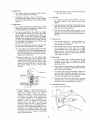
While holding the arm latch knob with one hand,
fingers of other hand as shown, between
column
and column
radial
arm
support.
Apply
gentle side force to the
in opposing
directions._
Any
looseness
between
column
and column
arrow) can be felt with fingers
Right
saw -
4_
and left
standing
hold
tube
support,
(indicated
positions
are given with operator
in front of the saw table.,
If looseness can be felt,
perform
operations
the
as follows:
a_
Loosen
set screw in center
b..
Loosen
left
c.
Tighten
right hand set screw until looseness between
column
and column
support
is eliminated_
Turn
elevation
crank to raise radial arm, if saw elevates
too hard, loosen right hand set screw slightly
and
hand set screw
again
check
elevation
looseness, When correct,
do Tighten
Elevate
elevation
Turn
tube
key°
t/4 turn.
and
column
tube
for
tighten left hand set screw.
set screw in center
of column
and lower arm and if chatter
exists, tighten
set screw until
operation
e.
of column
facing
by
tube key.
or rough
smoothest
is obtained.
elevation
crank
to raise and
lower
radial
arm.
If too tight, loosen right hand set screw slightly and
check
again for smooth
operation.
When correct,
tighten
left hand set screw.
Tighten
set screw in center
of column
until smoothest
operation
is obtained
STEP THREE
SQUARING
CROSS
CUT
TRAVEL
TRAVELS IN A STRAIGHT LINE),
t,
Lower
Lock
2o
Place
arm until
the yoke
a framing
position
the
just contacts
3,
saw
clamp
blade
handle
square
on
just
clears
(CARRIAGE
the front
table_
and bevel lock knob.
the
table
as shown
and
blade and square until the leg of the square
a tooth of the blade° Mark this tooth°
When the carriage is moved back and forth on the radial
arm, the marked
tooth should just touch the square at
all points. If marked tooth does not touch the square at
all points, make the following
adjustments:
I0
tube
key
/
If marked
tooth
moves into the square when moving
the blade from
the rear toward the front of the table,
tap the left hand front edge of the table with a mallet as
shown
(Loosen
table
attaching
screws
slightly
if
necessary)_
If the
marked
tooth
moves
away from
moving saw from the rear to the front
the right hand front edge of the table.
the square
when
of saw table,
tap
\
4,
Recheck
and,
screws securely
if
correct,
tighten
all table
Set fndicator
at 0 ° position.
NOTE:
This
simultaneously
positions°
squaring
of
set BOTH
the
of
hold-down
cross cut
travel
will
the 450 miter
index
In extreme
cases, the above adjustment
procedure
may
not
be sufficient
due to rough
handling
during
shipment,,
Make the following
adjustment
only after
tightening
the table hold-down
screws and the cross cut
cannot
be
squared
according
to the
preceding
adjustment
routine,
ao
Remove
radial
arm cap and miter-scale
b.
Turn
the
arm
counterclockwise.
latch
knob
co Loosen (do not remove) two
located inside the column tube°
Move
make
indicator.
one-quarter
hex-head
turn
screws
the radial arm slightly
in proper direction
marked tooth follow edge of square when
saw blade
manner.
is moved
along
arm
in
a "cross
to
the
cut"
e., Retighten the hex head screws in column
retighten arm latch knob
tube,
1.
Lay the rear table board on edge across the front table
to serve as a straightedge, Sight under this straightedge
to determine whether the front table board is high or
tow at its center_
2,
If the front
table is high at center,
first tighten
center (_ - 20 x I-1/4 inch) hold down screw until
table is level - then tfghten the fevel_ng screw until
screw _ssnug°
If table is low at center, first tighten the leveling
until the table is Jevel - then tighten
the hold
the
the
this
screw
down
Sel'ew.
11
f,
Recheck
travel
of blade
g.
After
the cross cut has been accurately
install the radial arm cap and miter-scale
Set the indicator
at the 0 ° position.
squared,
_ndicator.
unpacking
and
assernbly
3,,
Position
the rip (guide)
fence, spacer board and rear
table board behind the front table board, as shown,.
4,
Install
the two table
them at the rear of
securely.
clamps in the slots provided
for
the saw base, and tighten
them
NOTE:
The life of your saw table will be lengthened
considerably
if you will cover the front
table with a
fitted
piece of ¼ inch plywood_
This should be tacked
in place for easy replacement.
Use of such a cover will
allow you to do all cutting
into the cover, rather than
your table top_
FRONT TABLE
STEP 4
SQUARING
SAW BLADE TO (WORK) TABLE
NOTE: If alignment
procedure
step one was not
this adjustment
can not be accomplished.,
1
2=
performed,
BEVEL LOCK
Place a framing
square on the table with the short leg
against the saw blade,, Do not allow the square to rest
against a "set-out"
tooth;
it must rest flat against the
blade side.
If the
saw blade
is square
with
the table top
KNOB
(no visible
gap appears between the saw blade and square) and no
adjustment
is required.
Set bevel indicator
to 0 °
reading.
If the square does not touch the saw blade as
shown (with square leg held firm against the table top},
perform
the following
adjustments:
a
Loosen bevel lock knob 1/4 turn only, then loosen
the four
socket-head
screws, two on each side of
handle.
Rotate motor
while holding
square firmly
against saw blade and table top..
bo
Slightly
tighten
each of the two screws and recheck
.... Now tighten each screw firmly,, Retighten
bevel
lock knob,
c.,
Adjust
indicator
Q
SQUARE
%
WRONG
to 0 ° readlng_
WRONG
I
RIGHT
STEP 5
SQUARING BLADE TO RIP (GUIDE)
HEEL ADJUSTMENT,
FENCE - BLADE
NOTE:
If alignment
procedure
steps two and four were not
performed,
this alignment
step cannot be accomplished.
1.
Place a framing
square
blade, as shown. The
against the rlp fence and the saw
long leg of the square must be
RIP FENCE
held firmly
against both the fence and the table top,
and the short leg must not touch any of the teeth on
the saw blade,,
2.
If
the
square
does
not
touch
the blade
at both
of the
two points as shown, a hee} condition
exists (either
the left or right) or sometimes called heel or toe,
to
SQUARE
FENCE
SQUARE
FENCE
F -f
]
FENCE
Jz
1
F"
SQUARE
WRONG
12
i_
3.
To correct
proceed
for
either
type of "heel"
or "toe"
cbndition
as follows:
a.
Remove
left hand
b
Loosen
the yoke
clamp
c,
Loosen
(slightly}
the two
d,
Rotate
the yoke assembly
until
saw blade and square is eliminated,
e,
Lock
yoke
clamp
hex-head screws,
f°
Recheck
cover.
for
carriage
cover,
handler
hex-head
handle
"heel"
or
and
"toe"
HEX HEAD
SCREWS--
screws_
gap between
retighten
and
the
the
install
two
carriage
NOTE:
This alignment
procedure
will simultaneously
both yoke indexing
positions
for in and out rip,
set
LEFT SIDE OF
CAR_IAGF
STEP 6
ALIGNMENT
ASSEMBLY,
OF ANTI-KICKBACK
FOR RIPPING,
AND
SPREADER
lAB
WARNING:
NEVER
POSITION
THE GUARD
OR
ANTI-KICKBACK
ASSEMBLY WITH POWER ON; NOR
POSITION
ANTtq(ICKBACK
PAWLS BY GRASPING
PAWLS OR SPREADER. - USE TAB,
1o Check
a,
and adjust the spreader
as follows:
Loosen the wing screw and with the "tab" position
the anti-kickback
and spreader assembly to near the
bottom
of the blade° Tighten the wing screw°
Sight
(visually)
to check
for proper
alignment
of
spreader with saw blade as shown, tf the spreader is
not aligned, adjust it as follows:
(I)
Loosen
spreader
two
hex
nuts,
one
on
each
(2) Rotate hex nuts with fingers until
is directly in line with saw blade°
(3) Tighten
2.
INSTALLING
side
the spreader
both hex nuts firmly,
AND
ADJUSTING
RIP SCALE
INDICATORS.
NOTE:
The rip scales and pointers
are intended
used for quick
settings.
For greater
accuracy,
direct measurement
between blade and fence,,
Pre-assembie
indicator
and twin nut,
remove
the two screws which attach
cover.
b., Tilt
carriage
cover and install
rip
Tighten
carriage attaching
screws.
c.
Loosen but do not remove
hand carriage
cover,, Install
manner,
of
Tighten
carriage
loosen but do not
left hand carriage
indicator
carriage lock
rip indicator
attaching
to be
take
as shown.
knob in right
in the same
screws,,
_3
unpacking
d
and assernbay
With the fence in its normal position
(next to the front
table), loosen the yoke clamp handle, lift up on swivel
latch pin knob and rotate the yoke as shown to index
the yoke 90 ° from
the cross cut position.
This will
locate the saw blade between
the motor and the motor
and the fence.
clamp handle.
Loci{
the
yoke
by
tightening
F_NC_
FRONT
J
_A_L_
e
TAgL£
the yoke
Position carriage until the edge of the blade, when spun
by hand, just touches the front face of the fence.. The
rip-scale indicator
(on the right hand side of radial arm)
should
now read "0"
inches on lower portion
of the
"In-Rip"
scale_ If not,
loosen screws and shift the
indicator
until
it is aligned with
the "0" marl<, then
tighten the screws.
_AR
__,6LE
S_ACE_
BOARD
1
RI_' SCALE
_NDICA_OR
CARRIAG_ LOC_ ÷_NOB
!.
NOTE:
With the saw blade and fence in the position
shown, the tower portion
of the "In-Rip:
scale is used
If the fence is re-located
at the extreme
rear position,
the upper portion
of the "In-Rip"
scale would be used
The "Out-Rip"
scale indicator
on the left
hand
side of
the radial arm is adjusted
in essentially
the same manner
as the "In-Rip"
indicator,
except the fence should be at
extreme
rear and the blade positioned
as shown
With
12 inches measured
between
the fence (when in full
rear position)
and the face of saw blade, the rip-scale
indicator
should be positioned
to read 12 inches on the
upper portion
of the "Out-Rip"
scale.
t
NOTE:
With the saw blade and fence in the position
shown,
the upper
portion
of the "Out-Rip"
scale is
used. If the fence is moved to normal position
(at the
rear of front
table) the lower portion
of the "Out-Rip"
scale is used.
operating
F_NC_
g
R_AR
Loosen
latch
TA_L_
the
"
TABLE 5}_ACE_
BOARD
yoke
pin knob
!
clamp
and return
handle,
lift
up
on
the
swivel
the blade to the 90 ° position°
controls
RIP SCAL_
ON-OFF
WITH
SWIVEL
ARM LATCH
LATCH
PiN
INDtCATOR
SWITCH
KEY
KNO_
AND
SCALE
INDICATOR
LEV
COR D
ARM
LATCH
CARRIAGE
.LATCH
GUARD
ANT!
LOCK
KNOB
PIN HANDLE
CLAMP
KICKBACK
BEVEL
SPREADER ASSEMBLY
B_VEL
LOCK
INDEX
SCALE
KNOB
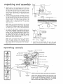
KNOW LOCATIONS
ELEVATION
AND FUNCTIONS
OF CONTROLS
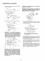
A series of six diagrams is located on the top surface of the
radial arm. These designate the controls
that must be used
in basic set-ups
and operating
procedures.
You
should
become
familiar
with
these diagrams
and the operating
instructions
that follow, before operating
your saw
CRANK
14
14 Depth
of Cut
a..
The diagram
shows the elevation
crank
used to raise and lower the saw btade_
b,.
Clockwise
rotation
raises
the
which
blade
(4) Lock the radial arm by rotating
knob clockwise
until tight_
is
....
3.
counterclockwise
rotation
lowers it.. One complete
turn of the handle will raise or lower the saw blade
1/8-inch.
2.
&
Angle of Cut
The arm is unlocked
from
counterclockwise
rotation
any position
of the arm
c,
by a slight
latch knob
and is locked
in any desired
miter
position
by
rotating
the arm-latch
knob clockwise
until
tight..
The radial arm has positive stops at 0 ° and 45 ° left
and right, and is released from these index positions
by unlocking
the arm-latch
knob
pulling out the arm-latch
lever.
c°
1/4-turn,
For the most positive
and accurate
settings
index positions, the following
is recommended:
(1)
4.
a.
and
at the
radial
arm
into
the
desired
index
5,,
position°
6.
(3)
The carriage loci< knob is rotated clockwise to
secure
the carriage on the radial arm, and
counterclockwise to release it,,
a square or miter-angle
crosscut,
lock
knob
must
be rotated
until the carriage is free to travel
Blade Angle
a°
The two controls
indexing
of the
saw-blade
(bevel)
bevel-index
knob_
b.
The bevelqndex
scale indicates the angular position
of the motor with respect to horizontal,
from 0 ° to
90 ° in either vertical position,,
c.,
The beve!
index knob
automatically
indexes the
motor
at 0 °, 45 ° and g0 ° up and down. Putl out on
the knob while positioning
the blade, then release
it At any other position
it does not engage..
d.
The bevel lock knob
locks the motor to the yoke
when the motor is in any position.
Rotate the knob
clockwise
to lock, counterclockwise
to unlock
\
LATCH
The yoke clamp handle locks the yoke to the
carriage in any position. Pull the handle forward to
release the yoke; push the handle rearward to secure
the yoke,
along
the arm° This
knob
should
be tightened
except when the operator
is ready to grasp the bevel
index handle and make a cut
position
(do not bump or jar it) and push on the
arm-latch
lever solidly
with
the palm of your
hand. This is very important
as it ensures proper
seating of the arm lock pin in the arm latch,
thus
always
setting
the arm at the correct
ARM
Two controls
are used in this operation° They are:
the swivel
latch-pin
knob
and the yoke clamp
handle.
When performing
the
carriage
counterclockwise
the locked position,
pull out the arm-latch
lever,
and move the radial arm off the index position.
Release the arm4atch
lever.
the
Pivot
Carriage Lock
If the radial arm is already indexed,
rotate the
arm-latch
knob 1/4-turn
counterclockwise
from
(2) Move
arm-latch
b,, A swivel latch pin automatically indexes the yoke at
each 90 ° position,, Lift the spring-loaded swivel
latch-pin knob to release this pin.,
ao Two controls are involved in releasing, securing and
indexing the angle of the radial arm. These are: the
arm4atch handle and arm-latch knob°
b,
Yoke
the
Power Switch and Key
a
KNOB
Precision
Indexing
- experienced
operators
of
precision
equipment,
such as this Craftsman
Radial
Saw,
normally
acquire
the habit
of
indexing
the machine
in one direction
only,
whenever'a
new setting is made in preparation
for a different
operation..
For example:
when
moving
the radial arm to a new position,
it is
advisable
to move it slightly
past the desired
index
position,
then
return
it slowly
and
carefully
to latch and loci< it, Swivel
indexing
and bevel indexing can be accomplished
in a
similar
manner. This indexing
technique
tends to
neutralize
any
stresses
imposed
upon
saw
components
and contributes
to the high degree
of accuracy
the saw is capable of producing
when operated expertly
\
15
used in angular positioning
and
motor,
to provide
the desired
angle, are: bevel lock knob and
Insert key into switch lock.
/
operating
b
insert finger under
out, to turn switch
confroas
end of switch
on.,
lever and pull
POSITIONING
ANTI-KICKBACK
ASSEMBLY, FOR RIPPING
end
AND
SPREADER
WARNING:
NEVER
POSITION
THE GUARD
OR
ANTI-KICKBACK
ASSEMBLY WITH THE POWER ON.
NEVER POSITION THE ANTI-KICKBACK
PAWLS BY
GRASPING THE PAWLS OR SPREADER.
PIECE
MINIMUM
GUARD
c.
Push lever in - wfth thumb - to turn switch off,,
CLEARANCE
ao The blade guard is positioned by Io9sening the guard
clamp screw and rotating the guard so that it just clears
the workpiece as shown.
READER
ANT I- K ICKBACK
PAWL
OFKICKBACK_\_
I'Jff [
\ J Dr,ECTtO.OFFEED
/_':_-
ANT I-KICKBACK
d,
WARNING:
THIS
LOCKING
FEATURE
IS
PROVIDED
TO PREVENT
UNAUTHORIZED
USE OF YOUR SAW° ALWAYS
REMOVE THE
KEY AND KEEP IT IN A SAFE PLACE° TO
REMOVE
KEY, HOLD THUMB ON END OF
LEVER TO KEEP SWITCH IN "OFF" POSITION
AND PULL KEY STRAIGHT OUT°
_"
,
POSIT ION
(Make
sure by trial before starting
the Anti-Kid{bark
Pawls will stop
once it has started)
the cut that
a Kick-back
b_
The anti-kickback and spreader assembly is used during
ripping operations and is adjustable to accommodate
the thickness of the board being ripped. A wing nut in
the guard secures the assembly.
c,
Loosen the wing screw and with the tab provided,
position the anti-kickback and spreader assembly until
the paw} assumes approximately
the position shown
above, Tighten the wing screw
Before making the cut, check the effectiveness of the
anti-kickback pawls by sliding the workpiece under the
pawls in the direction of feed and then attempting to
slide it in the reverse direction - the direction of
kickback° If the pawls do not catch, readjust_
WARNING: FOR YOUR OWN SAFETY ALWAYS
LOCK THE SWITCH "OFF" WHEN SAW IS NOT
IN USE° REMOVE KEY AND KEEP tT IN A SAFE
PLACE .,,ALSO
IN THE EVENT OFAPOWER
FAILURE (ALL YOUR LIGHTS GO OUT) TURN
SWITCH OFF. LOCK IT AND REMOVE THE KEY
THIS
WILL
PREVENT
THE
SAW FROM
STARTING
UP AGAIN
WHEN THE POWER
COMES BACK ON,
16
basic
saw operations
Basic sew operations
are summarized
into six categories,
explained
and /frustrated
in the following
paragraphs,,
A
manual
entitled
"The
Radial
Saw"
is available
at your
nearest
Sears Retail
Store or Catalog
Order House. This
manual
contains
considerable
data
and project
ideas
applicable
to the radial saw.
NOTE: Refer to paragraphs under "OPERATION"
illustrations and descriptions of controls.
REQUIREMENTS
for
FOR CROSSCUT
Board (stationary'}
position
laying fiat on tabte top.
against
(OPERATIONS
rip
fence
I THROUGH
(guide}
and
4)
1
Arbor
nut must be tight
in horizontal
position.
2.,
Arm
3.
Adjust
the anti-kickback
assembly
clear the workplace,
or fence,
4.
Work must be held firmly
against table and fence. For
workpieces
thicker
than
the
fence
is high,
it
is
recommended
that
a higher
fence be cut
(at least
workpiece
tMckness}
and inserted for that operation
being performed.
Always
place the fence in the most
forward
position
(farthest
from
the column
support)
compatible
with the workpiece
being processed and the
operation
being
performed.
With
the carriage
fully
retracted,
the blade should
not contact the workpiece
when
pfaced against
the fence,
within
the stated
capacities of your saw.
latch
handle
(knob)
and saw blade guard
must
installed
be tight
pawls
_ust
Blade should
6.
Hands must be kept
well away from
7,
Yoke
must be in locked
8.,
Bevel index
9
Blade should cut into
more than 1/32 inch,
I0.
Pull the saw forward
just far enough
to sever the
lumber.
It is dangerous
if the blade has been pulled too
far out beyond
the piece being cut When it is returned
it can pick up the right hand piece and throw it over the
fence
t1_ For
handle
knob
operations
PROPER
DIRECTION
OF TRAVEL
5.
clamp
be sharp and correctly
so the
set.
_
saw biade,
position
must be tight
No_
instructions
under
"Blade
Angle"
OPERATION
the
table
3 and
paragraph
No,
or plywood
4,
cover
observe
"Operating
(SEE ITEM
not
AT
LEFT}
IMPROPER
additional
Controls"
"10"
-
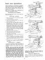
No. 1 - CROSSCUT
Crosscutting
is the process of sawing the workplace
by
pulting
the saw blade through
it and using the fence as a
support
for the edge of the workpiece.
Never crosscut
free-hand.,
DIRECTION
WARNING:
BEFORE CROSSCUTTING,
MAKE SURE
THE ARM LATCH, BEVEL LOCK AND YOKE CLAMP
ARE ALL SECURED. NEVER USE A LENGTH STOP OR
A FIXED GUIDE ON THE FREE END OR EDGE OF A
WORKPIECE. (SEE INSTRUCTION
7 UNDER "SAFETY
INSTRUCTIONS
TO OPERATOR".) DO NOT CROSSCUT
WORKPIECES THAT PLACE YOUR HANDS CLOSE TO
THE
PATH OF THE SAW BLADE. WHEN MORE
EXPERIENCE
IS GAINED BY USING THE SAW, IT
WILL BE NOTICED, THAT WHEN PULLING THE SAW
TOWARD YOU DURING CROSSCUTTING, THE BLADE
TENDS TO FEED ITSELF THROUGH THE WORK DUE
TO THE ROTATION
OF THE BLADE AND THE
DIRECTION
OF THE
FEED. THEREFORE,
THE
(SEE ITEM
"t0"
AT
LEFT)
OPERATOR
SHOULD
DEVELOP
THE
HOLDING
HIS RIGHT ARM STRAIGHT
SHOULDER TO THE WRIST.
REPETITIVE
HABIT
OF
FROM THE
CROSSCUTTING
Clamp
a "C" clamp (min, 6 inch) using a wood block on
each side of the arm,, This wilt limit
the carriage travel
beyond
the position
necessary
to complete
the crosscut
operation,
I7
basic
OPERATION
opera ions
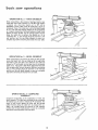
No. 2 - MITER
CROSSCUT
Miter crosscutting is the process of sawing a board at any
angle other than a 90 ° (square) cut° The 45 o miter angle is
a popular one, since two boards cut to 45 ° can be
assembled to form a 90 ° corner for producing a square or
rectangular frame. The radial arm is set to the desired angle
of cut; yoke and bevel settings indexed at 0 ° (and locked)
as in square crosscutting. The board being cut is held firmly
against the fence (guide) and the carriage pulled forward
along the radial arm to perform the desired cut_ As in
"Operation No, !"', the carriage should be returned to full
rear position and the saw blade allowed to come to a
complete stop before removing the boards from saw table°
OPERATION
No. 3 -
BEVEL CROSSCUT
Bevel crosscutting
is the process of sawing at 90 ° (square)
across the board with
the saw blade set at an angle other
than 90 ° to the saw table, The radial arm and yoke are
indexed at 0 ° and locked, but the bevel is set to the desired
angle of cut,. The board is held firmly
against the fence and
the carriage pulled forward
along the radial arm to produce
the cut. The carriage should
be returned
to full rearward
position
and the saw blade allowed to come to a complete
stop before removing
the boards from saw table.
OPERATION
No. 4 - COMPOUND
CROSSCUT
Compound
crosscutting
is the combination
of miter and
bevel crosscuts.. The radial arm and bevel are set to produce
the desired cut; the yoke is indexed at 0 ° and iocked_ The
board
is held firmly
against the fence and the carriage
pulled forward
along the radial arm to produce
the cut.
Again,
the carriage
should be returned
to full rearward
position
and the saw blade allowed to come to a complete
stop before removing
boards from saw table.
18
REQUIREMENTS
WHEN RIPPING
(OPERATIONS 5 AND 6)
1,
Carriage
lock
knob
2.,
Radial
3,,
Work must be held firmly
feeding through,.
4,
Guard and anti-kickback
set., Observe
instructions
Guard,
and Anti-Kickback
(I-
PUSH
PUSH
ST ICt_
INCH
SQUARES)
STICK
must be tight,,
arm must be locked
in 0 ° position,,
against
table and fence while
mechanism
must be properly
in paragraph,
"Adjusting
and Spreader Assembly
for
PUSH STICK
R ipplng."
5_
Blade
should
be sharp and correctly
set_
6,
When ripping narrow stock,
than
I/2
inches between
(guide), use a push stick,.
7,
When ripping
stock I/2 inch or less between
and fence (guide) use a pusher board,
tess than 3 inches but more
the guard and the fence
the
btade
Pusher board should not be less than 3 inches wide and
16 inches long, Nail or glue a 3/4 x 3/4 x 4 inch block
to one edge of push board to be used as a grip,
PUSHER
BOARD
The pusher board should be fed into the blade behind
the stock being ripped not more than 8 inches so as not
to strike anti-kickback
pawls fingers and then pulled
back with use of the grip°
8.
Hands must be kept well away from saw bladed
g,,
Saw blade must be parallel
possibility of kickbacks.
to
fence,
to
minimize
OPERATION
No. 5 - OUT-RIPPING
AND IN-RIPPING
Ripping
is the
process
of
sawing
the
workpiece
WARNING:
NEVER
RIP FREE-HAND.
BEFORE
RIPPING, MAKE SURE THE GUARD, SPREADER
AND
ANTI-KICKBACK
PAWLS ARE SET UP
PROPERLY, ALSO, MAKE SURE THE SAW BLADE
IS PARALLEL
WITH THE FENCE. NEVER
RIP
WORKPIECES SHORTER THAN THE SAW BLADE
DIAMETE R.
by
feeding it into the saw blade when using the fence as a
guide and as a positioning
device to obtain
the desired
width of cut,
19
basic
saw operations
2o
Since the work is pushed along the fence, it must have a
reasonably
straight
edge in order
to make
sliding
contact with the fence, Also, the work must make solid
contact
with
the table,
so that it will
not wobble.
Provide a straight
edge, even if this means temporary
nailing of an auxiliary
straight-edged
board to the work.
If the workpiece
is warped,
turn the hollow side down.,
3,,
Always
use the saw guard and make sure the spreader is
correctly
aligned with the saw kerr, Wood cut with the
grain tends to spring the kerf closed and bind the blade
and a kickback
could occur°
4,
Stand
a Httle to one side of center
to avoid being
sprayed with sawdust and to be clear of work in case of
kickback,
5°
When ripping short or narrow
stick applied
to the section of
the Made and fence
,,, push
so it is clear of the blade. This
the possibility
of kickbacks
\
work, always use a push
the workpiece
between
the work past the blade
procedure will minimize
In-Ripping.
The radial arm and bevel are indexed at 0 ° and
locked,
but the yoke is turned
90_degrees in a clockwise
direction
(viewed
from above) from the crosscut position,
Thus, when standing
in front of the saw, the blade would
be rotating
counterclockwise,
After
positioning
the guard
and anti-kickback
mechanism
the workpiece
is fed from the
right-hand
side of the saw° The "In-Rip"
scale is on the
right-hand
side of radial arm,,
OPERATION
No. 6 -
BEVEL
Out-Ripping
The radial arm and bevel are indexed
at 0 °
and
locked,
but
the yoke
is turned
90-degrees
in a
counterclockwise
direction
(viewed from above), from the
crosscut position
When standing
in front of the saw, blade
would
be rotating
clockwise
After
positioning
the guard
and anti-kickback
mechanism
the workpiece
is fed from the
left-hand
side of the saw The "Out-Rip"
scale is on the left
hand side of radial arm.
RIPPING
Bevel ripping
is either in-ripping
or out-ripping
as described
above, except the saw blade is tilted out of perpendicular
to
the saw table surface° The radial arm is indexed at 0 ° and
locked,
the beve_ is set to the desired bevel angle and the
yoke
is positioned
for in-ripping
(saw blade at rear) or
out-ripping
{saw
blade
at front},
as required,,
All
requirements
and observations
applicable
to normal ripping
operations
also apply to bevel ripping,
DADOING
Instructions
for operating
the Dado Head are contained
booklet furnished
with the Dado Head.
MOLDING/SANDING
in
Instructions
in a booklet
The saw arbor
is designed
for dado heads up to !3/16
inches wide. Do not install a wider dado head on the arbor.
Take several passes if required dado cut exceeds 13/16 inch.
When
instal!
for operating
the Molding
furnished
with the Molding
Head are contained
Head
For use of Molding
Head Cutter or Drum Sander the rear
table requires an opening for clearance
Cut this opening as
shown.
installing
the dado head on the arbor,
ALWAYS
the inside "loose
collar"
first_ Be sure the teeth of
the chippers
are placed to fall in blade gullets, and chippers
are approximately
equally spaced around the arbor..
DO
arbor
outer
NOT
install
the
outside
loose
nut is tight
Install the arbor
blade of dado head,
collar.
Make
nut directly
REARTABLE-_[
sure the
against the
For best results and to avoid excessive load on the motor,
NEVER CUT A 13/16" WIDE DADO, DEEPER THAN
3/4" IN ONE PASS
2O
"-tF_1,b3"
12-1/2"
j ......
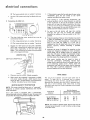
electrical
connections
POWER SUPPLY
Motor
tt is recommended
that you have a qualified
replace the TWO prong outlet with e properly
THREE prong outlet.
Specifications
The A-C motor
used in this saw is a capacitor-start,
non-reversible
type having the following
specifications:
Voltage
...................................
Amperes
.................................
Hertz (cycles)
.................................
Phase ..................................
RPM
Rotation as viewed from saw blade end
An adapter as shown below
plugs to 2-prong
receptacles.
extending
from
the adapter
120/240
1I/5.5
60
Single
3450
Clockwise
.........................................
....
permanent
outlet box.
ground
such
is available for connecting
The green grounding
lug
must be connected
to a
as to
a
properly
GROUNDING LUG
MAKE
3-PRONG
II
YOUR OUTLET iS
IT CHECKED BY A
A
GROUND
ELECTR ICAL CONNECTIONS
WARNING:
CHANGES
CONNECTIONS
SHOULD
QUALIFIED
ELECTRICIAN.
IN
BE
ELECTRICAL
MADE
BY
A
1. Changing Motor Connections
a.
Under normal home workshop
usage, and if proper
(full) voltage is supplied
to the motor, your saw will
operate efficiently
on 120V,
as connected
at the
factory.
However,
if any of the following
conditions
exists, it will be advisable for you to reconnect
the
motor
for
240V
operation
to obtain
the
efficiency
and performance
for which your saw is
designed:
(1) Heavy-duty
(2) Either
circuit
If your unit is for use on less than 150 votts it has a
plug that looks like below,
(3) Low
which
PLUG
bo
PROPERLY
D ]
G_I OUNOING
KNOWN
NOTE: The adapter illustrated is for use only if you
a{ready have a properly grounded 2-prong receptacle,
Adapter is not allowed in Canada by the Canadian
EIectricaF Code.
IF POWER CORD IS WORN OR CUT, OR DAMAGED
IN ANY WAY, HAVE lT REPLACED IMMEDIATELY.
/" n
IS
TO
2-PRONG
WARNING:
IF NOT PROPERLY GROUNDED THIS
POWER
TOOL
CAN INCUR THE POTENTIAL
HAZARD
OF
ELECTRICAL
SHOCK,
PARTICULARLY
WHEN
USED
tN DAMP
LOCATIONS tN PROXIMITY TO PLUMBING. IF AN
ELECTRICAL
SHOCK OCCURS THERE IS THE
POTENTIAL
OF A SECONDARY HAZARD SUCH AS
YOUR HANDS CONTACTING THE SAWBLADE_
OUTLET
THIS
RECEPTACLE
WARNING:
DO NOT PERMIT FINGERS TO TOUCH
THE TERMINALS
OF PLUGS WHEN INSTALLING
OR REMOVING
THE PLUG TO OR FROM THE
OUTLET,,
GROUNDED
SURE
CONNECTED
PLUG
This machine must be grounded while in use to protect
the operator from electric shock.,
3-PRONG
grounded
ADAPTER
CAUTION:
Your saw is wired for 120V operation_
Connect to a t20V, 15-Amp, branch circuit and use a
15-Ampr time-delay
fuse or circuit breaker, if the
motor is used for 240V operation, connect to a 15-amp.
branch circuit and use a tS-Ampo tlme-delay fuse or
circuit breaker_
IF YOU ARE NOT SURE THAT
PROPERLY GROUNDED, HAVE
QUALIFIED
ELECTRICIAN.
electrician
grounded
PRONG
an
operations.
undersized
serving
or an overloaded
branch
the saw motor.
voitage
supplied
by the power
source,
the power company
cannot correct.
Motor wiring
connections
for 120V (as made at tile
factory)
are
described
below.
Necessary
reconnections
for 240V operation
are also described
foflowing.
Whenever
changing
connections
from
120V to 240V or vice-versa,
make certain that all
necessary
steps (including
proper
fusing
of the
branch circuit)
are completed,
2_ Connections
for 120V
A.Co
This power toot is equipped
with a 3-conductor
cord
and grounding
type plug which has a grounding
prong,
approved
by
Underwriters'
Laboratories
and
the
Canadian Standards
Association°
The ground conductor
has a green jacket and is attached to the toot housing at
one end and to the ground
prong in the attachment
plug at the other end,
This pSug requires
outlet as shown,
If the outlet
is of the
ALTER
a mating
grounded
type
a.
you are planning
two
THE
3-conductor
to use for this power
prong
type
DO
GROUNDING
MANNER.
Use an adapter as shown
the grounding
lug to known ground.,
NOT
REMOVE
PRONG
IN
and always
tool
OR
ANY
Remove
terminal
namepiate
board.
cover
from
motor
to
expose
b,. The wires inside of the motor must be connected as
shown:
connect
(1) The orange-colored
21
wire
on number
6 terminal,
eUectrica8 connections
c
(2) The
brown-colored
Use the
120V
wire
power-cord
on number
5 terminal,,
plug furnished
with
If the protector
opens the line and stops the saw motor,
immediately
press the
saw switch
to the "OFF"
your
position,
saW.
3o
Connections
for 240V
and allow
After
cooling
to
overload
protector
A.C_
the motor
to cool
a safe operating
temperature,
the
can be closed manually
by pushing
in the red button
on the top of the motor,
button will not snap into place immediatety,
is still too hot and must be allowed to cool
longer..
audible
O0k
3_
As
a,
The wires
connected
motor
terminal
box
be
4_
wire
(2) The brown-colored
wire on number 7 terminal.
the
120V
on number
power-cord
plug with
240V
plug, connecting
the power-cord
black
leads, respectively,
to the two
blades - and connecting
the power-cord
wire
240V
must
(1) The orange-colored
Replace
b_
inside the
as follows:
PLUG
to the plug ground
8 terminal
a (3-blade)
white
and
"hot"
plug
grounding
& RECEPTACLE
ADAPTER
AVAILABLE
THIS
TYP_
button
will
snap
into
running
may
be started
and
operated
out the saw switch to the "ON"
opening of fuses or circuit breakers may result
is overloaded,
or if the motor circuit
is fused
5.
Although
the motor
is designed
for operation
on the
voltage and frequency
specified
on motor
nameplate,
normal
loads will be handled
safely on voltages
not
more than 10% above or below the nameplate
voltage
Heavy loads, however,
require
that voltage
at motor
terminals
equals the voltage specified on nameplate
6.
Most
motor
troubles
may
be traced
to loose or
incorrect
connections,
overloading,
reduced
input
voltage (such as small size wires in the supply circuit)
or
to an overly-long
supply
circuit.
Always
check
the
connections,
the load and the supply circuit,
whenever
the motor
fails to perform
satisfactorily.
Check wire
sizes and lengths with the table following.
_S
PLUG
Plug your saw into a 240V, 3-blade receptacle.
d,
Make certain the receptacle is connected to a 240V
A-C power supply through a 240V branch circuit
having at least a 15_amp,.capacity, and protected by
a 15-amp. time-delay fuse or circuit breaker°
SAFETY
red
the
saw
by pulling
FOR
c.
MOTOR
Frequent
if motor
as the
(An
differently
from
recommendations..
Overloading
can
occur
if you
feed too
rapidly
or if your
saw is
misaHgned so that the blade heels,. Do not use a fuse of
greater
capacity
without
consulting
a qualified
electrician.
prong,
tllO
In some cases this may take 20-30 minutes.
click will indicate
protector
is cIosed.)
soon
position,
normally,
position.
ff the red
the motor
for a while
WIRE SIZES
The use of any extension
cord wilt cause some loss of
power.
To
keep
this to a minimum
and to prevent
over,.heating
and motor
burn-out,
use the table below to
determine
the minimum
wire size (A.W GJ extension
cord
Use only
3 wire
extension
cords
which
have 3 prong
grounding
type plugs and 3-pole receptacles
which accept
the tools plug,
PROTECTION
NOTE; This motor should be blown out, or "vacuumed",
frequently
to prevent sawdust interference with normal
motor ventilation.
Length of the
Conductor
Your
saw
motor
is equipped
with
a manual-reset,
thermaboverloed
protector
designed to open the power-line
circuit when the motor temperature
exceeds a safe value,
Up to 100 feet
t00 feet to 200 feet
200 feet to 400 feet
Wire Size Required
(American Wire Gauge Number)
240 Volt Lines
120 Volt Lines
No., t4
NOr 12
No. 8
No. 12
No_ 8
No. 6
NOTE:
For circuits
of greater length, the wire size must be
increased proportionately
in order to deliver ample voltage
to the saw motor..
22
troubae=shoofing
WARNING:
REMOVE
POWER
CORD
SOURCE
BEFORE
TROUBLE
SHOOTING.
FROM
POWER
The usual
paragraphs
Even'
though
the
finest
materials
and precision
workmanship
have been incorporated
into your Craftsman
saw, it is reasonable
to expect some wear after long periods
of use., Sooner or later, the metal to metal parts must wear
and will need take-up.
Every metal to metal part on your
Craftsman
saw can be taken up, In this way, the machine
can always be kept accurate and just as important,
rigid.
LOOSENESS
OF COLUMN
TUBE IN COLUMN
SUPPORT
ELEVATION
CRANK
OPERATES
ROUGHLY OR CHATTERS WHEN ROTATED°
Refer to Step two in Alignment
Check for looseness (movement)
column support,
FINISH
2.
RADIAL
SAW DOES NOT MAKE
45 ° MITER CROSSCUTS,
ACCURATE
a.
tube
Looseness
between
column
operating
"troubles"
are listed in the following
with the necessary corrections
listed,
CUT
Procedure Section
of column tube in
FINISH CUT _ND
END
0° or
and
column
Procedure
Section
support..
Align as described
Step Two.
in Alignment
_ 5QUAKE
Improper
arm indexing
Refer to
section
precision
at 0 ° crosscut_
indexing
in
operating
controls
FENCEEDGE
FINISH
c.
Crosscut
Refer
Section
travel
not properly
to Step
Squaring
CUT
LOOKS
LIKE
FENCE EDGE
THIS
-
0 ° CROSSCUT
adjusted°
Three
in Alignment
Crosscut Travel°
Procedure
45 ° MITER
l
3.
SAW
a.
CUTS
Table
AT
support
Refer
to
Section
b,
4o
ANGLE
NOT
channels
Step
90 ° TO TABLE
not properly
One
under
THIS
--
TOP.
leveled
Alignment
¢.HOULD
Procedure
BE 90 _
ANGLE
Blade
not square
Refer
to Step four
BLADE
-
OR LIKE
ANGLE
to work
table
in Alignment
(BEVEL)
CUTS
\
top,,
Procedure
NOT
Section,
ACCURATE.
SQUARE
a.
Corrective
above.
d.
Carriage
Refer
action
is the
Bearings
Loose
to Step four
same as paragraph
in Alignment
Procedure
3a and b
Section
5. SAW KERF (CUT EDGE) OF STOCK ROUGH
TOOTH MARKS LEFT ON EDGE OF SAW KERF.
-
NOTE:
"'TOE'L
or
a.
This condition
is commonly
called
"HEEL"
ROUGH
r,ER_
_DGES
'
"
L
_._ WIDE CUT
_
_J--
FENCE
(KERF)
.
_L
Crosscutting
or Miter
Cutting
.._
_
Heeling will tend to slide the workpiece
toward the
right along the guide fence, as the cut is being made,
and make a square cut almost impossible,, A blade
with
"toe"
will tend to slide the board to the left
along the fence.
Refer to step 5 under Alignment
- "Squaring
Blade to Fence",
Procedure
Section
23
"/
DIRECTION
_-_-,___
ATT_MF_EO
BLAD_ TRAVEL
OF
- =
-_
O_[CI[ON
OF
--
gLADE _AVSL
_
-
_
'
trouble--shooting
6.
WOOD
BINDS, SMOKES AND MOTOR
DOWN OR STOPS WHEN RIPPING°
a°
Dull blade or warped
SLOWS
TOP VIEW
WITH
ARM 90 ° TO THE
FENCE
board°
FENCE
Sharpen or replace the saw blade. Avoid
attempted use of severly warped material
the
bo Radial arm not securely locked in 0° position.
Loosen the arm lock knob and refer to paragraph
"Precision Indexing",
c.
Crosscut not properly
squared_
Check
and align
as described in Alignment
Procedure Section, Step Two and Three, Squaring
crosscut automatically
corrects this condition for
ripping.,
d,
HEEL
Saw blade heels,
Check
and
align
as described
Procedure
Section, Step Five,.
7.
BOARD
RIPPING,
a,,
PULLS
FROM
Alignment
FENCE
FENCE
i
WHEN
action
explained
1
'
Anti-kickback
adjusted_
and
is the
same as preceding
in paragraphs
D and E
spreader
assembly
not
CARRIAGE
WITH
properly
FENCE
PARELLEL
Refer
to "Adjusting
Guard,
Anti-Kickback
Spreader Assembly,
For Ripping'o
8,
TOE
Saw blade has toe°
Corrective
instructions
b.,
AWAY
in
INCORRECT
BEARINGS
__-
and
CORRECT
LOOSE.
To test for looseness between bearings and tracks on
radial arm, perform the following steps.
a,
Remove left-hand carriage cover.
b.
Push the carriage to its full most rearward position,,
c.
Finger hold front carriage bearing as shown and
apply as much force as possible and at the same
time pull carriage forward,
If you can stop the
bearing from turning it will require adjusting°
d.
Check rear bearing in the same manner and adjust as
follows:
t_
Loosen nuts just enough to permit the eccentric
screws to turn.,
2,
Rotate the eccentric screws a partial turn
or right) as required to take up looseness,
3_
Hold
position
tighten
the
heads
of
eccentric
screws
in
(left
ECCENTRIC
SCREW
the
established
in the preceding
step and
nuts on underside
of carriage, Correct
adjustment
exists when
bearings from turning°
you
cannot
keep
the
24
INCORRECT
9.
YOKE DOES NOT INDEX
PROPERLY,
Check for proper yoke indexing
noting
that the swivel
latch pin fits into its detents
properly,
tf swivel latch
pin housing
screws (located
under
left hand carriage
cover)
are loose, readjust blade for "hee!"
or "toe"
as
described
in Alignment
Procedure
10, YOKE CLAMP HANDLE
Section,
Step Five.
ADJUSTMENT,
The normal
locking
position
of the yoke clamp handle
is approximately
midway
between
the two sides of the
yoke. When sufficient
wear has occured to permit
the
handle to move considerably
to the rear, or strike the
yoke before
locking, the handle must be adjusted
as
follows:
a.
Set yoke clamp handle to Normal Locking Position
which is just slightly ahead of the mid-position.
b_
Remove carriage stop screw and lockwasher with a
3/16 inch hex-L wrench_
c,
Grasp
the
carriage
assembly,
holding
it parallel
to
the radial arm until al! carriage bearings are free of
their tracks, move it carefully
off the end of radial
arm,
d.
e,,
Rest the motor
table and remove
and carriage
assembly
the lock screw.
on
saw
_d
more_
f_
Install
g
Hold the motor and carriage assembly parallel to radial
arm
and start
the rear
bearings
onto
the tracks..
Continue
to hold the assembly paralle!
to the tracks
until
and tighten
the forward
the lock
bearings
screw,
are on the tracks
Slide the carriage rearward on the radial arm and install
the carriage stop screw and Iockwasheh
25
"_
II
i_
Using a screwdriver,
rotate
the yoke clamp assembly
clockwise
until the next hole will fine up with the lock
screw.. Usually
rotating
the yoke clamp assembly one
hole will correct
this adjustment.
However,
in some
extreme
cases it may be necessary to rotate it two holes
or
h,,
LOCK
SCREW
work
!
/
YOKE CLAMP
HANDLE
trouble
shooting
MOTOR
NOTE:
TROUBLE
Motors
- SHOOTING
used on wood-working
susceptible
to the accumulation
and should be blown
out or
prevent
TROUBLE
Motor
interference
PROBABLE
will not run,
l r Protector
broken_
with
t. Short
normal
open;
SUGGESTED
circuit
1. Power
Reset protector
by pushing on red button,
located on top of motor (indicated
by
audible click),,
in line,
1
too
or
fuses in power
line overloaded
lights, appliances
motors..
2. Undersize
24 Inspect
shorted
line
with
wires
or circuit
feed rate when
circuit
correct
fuses,
t. Reduce
the line load
2 Increase
wire
3 Request
a voltage
sizes, or reduce
length
check from
the power
"I. Slow down
rate of feed.
cooling
(Air
restricted
2. Clean out
circulation
sawdust to provide
through
motor,
normal
air
due to
3 Refer to Alignment
manual Step Five.
Procedure Section of
1. Correct
low voltage
condition
t. Voltage too low to permit
motor to reach operating
speed.
I. Correct
the low line voltage
2. Fuses or circuit breakers
do not have sufficient
2. Replace fuses or circuit
proper capacity units,
t
Low Voltage - will
starting switch.
not
trip
condition
breakers
capacity..
Frequent opening of
fuses or circuit breakers,
of wiring..
or ripping..
3o Saw blade has "heel"_
in
Install
the capacity of existing
generating
and distribution
sy stem s.)
through motor
sawdust, etc_)
stalls (resulting
tripped
breakers).
3
all terminals
in motor for loose or
terminals
or worn insulation
on wires°
and other
3o General overloading
of
power company's
facilities,
(In many sections of the
country,
demand for
electrical
power exceeds
2. improper
circulation
blown fuses or
Inspect line, cord and plug for damaged
insulation and shorted wires
long.
crosscutting
Motor
REMEDY
2 Check power line for proper voltage
circuit
t. Excessive
Motor starts slowly or
fails to come up to full
speed.
ventilation.
cord or plug
3 Incorrect
Motor overheats.
motor
and wood chips
frequently
to
CAUSE
2. Short circuit
in motor
loose connections.
Motor fails to develop
full power. (Power output
of motor decreases rapidly
with decrease in voltage at
motor terminals,, For
example: a reduction of
10% in voltage causes a
reduction of 19% in
maximum power output
of which the motor is
capable, while a reduction
of 20% in voltage causes
a reduction of 36% in
maximum power output.)
tools are particularly
of sawdust
"vacuumed"
2 Low voltage
Motor will not run and
fuses "BLOW"°
CHART
1°Motor
2
overloaded.
1. Reduce
motor
Fuses or circuit breakers
do not have sufficient
2. Replace
fuses or circuit
capacity,
26
load.
breakers.
with
company
maintenance
and
lubrication
MAINTENANCE
WARNING:
FOR YOUR OWN SAFETY, TURN SWITCH
"OFF"
AND REMOVE PLUG FROM POWER SOURCE
OUTLET BEFORE MAINTAINING
OR LUBRICATING
YOUR SAW_
When
you
receive
your
new Craftsman
radial
saw, it
requires
no lubrication,,
The radial saw has been partially
aligned and all bearings are lubricated
and sealed for life. In
time,
however,
in order
to keep your
saw in perfect
working
order and accurate, it will be necessary to lubricate
and realign,
in fact,
your
radial
saw needs more of a
cleaning than a lubrication_
Make sure the teeth of the ANTI KICKBACK
pawls
always sharp.. If they become dull, repface immediately
are
LUBRICATION
Your saw is precision built and should be kept clean and
properly lubricated° Before describing the various points
which may periodically require lubrication,
IT IS MORE
IMPORTANT
TO FIRST MENTION
THE VARIOUS
POINTS WHICH SHOULD NOT BE LUBRICATED,
NO LUBRICATION
REQUIRED
Do not lubricate carriage ball bearings or motor
these
are sealed
ball
bearings
and require
lubrication.,
Do not
lubricate
between
PERIODICALLY
radial
arm cap and radial
LUBRICATE
OIL
bearings as
no added
arm.,
THESE POINTS
Use SAE No,, 10W-30 automotive engine oil and refer to
Parts List for locations. Apply a few drops of oll along the
swivel latch pin only if the pin has a tendency to stick.
Remove the left-hand carriage cover and use oil sparingly to
prevent it from getting on the ball bearings or races,
A light film of oil should be wiped on the face of the
column tube and keyway to lubricate the fit between the
column tube, the key and column support,
Apply a few drops of oil to the bearing surfaces of the
elevation crank shaft assembly. An oil hole is provided in
the elevation shaft bearing bracket to facilitate
the
lubrlcation of the bearing support°
The thread on the elevation
shaft assembly can be
lubricated through the oil hole in the center of the radial
arm cap,,
CAUTION:
Excessive oil at any
airborne dust particles and sawdust°
location
will
attract
27
HOLE
recommended
accessories
IN CANADA, SEE YOUR LOCAL SIMPSONS-SEARS STORE
OR CATALOG FOR ACCESSORY SELECTION AND NUMBERS.
ITEM
CAT,NO.
Cabinet
.............................................
Stand ..........................................
Steel Legs ...................................
Castors ...........................................
Hold-Down Attachment
.......................
Key Chuck ....................................
*Molding Head Guard - 7-inch
................
*Moiding Head Guard -- 8-inch
.................
Rotary Surface Planer - Carbide Tip .............
Sanding Wheel - 8-Inch ............................
Sanding Wheel - !O-Inch .........................
Dust Collector
.....................................
Taper Jig .....................................
Satin Cut Dado - 7-Inch
...................
Satin Cut Dado - 8-Inch
.....................
*Molding Head Single Cutter
......................
* Molding Head Three Cutter
......................
Sanding Drum - 3-Inch ........................
oLower Retractable Guard
....................
"Power Tool Know How Handbook"
Radial Saw .....
-...........................
22203
22202
22211
22201
9-3230
9-2980
9-29524
9-29523
9-29513
9-2274
9-22723
-2953"_
9-3233
9-3257
9-3253
9-3215
9-3221
9-25246
9-29009
9-2917
*Before purchasing or using any of these accessories, read
and comply with additional safety instruction No "14" on
p., 4 of this manual,,
o Meets OSHA
The above recommended
accessories
Requirements
are current
as of 8-73,
and were available
28
at the time this manual
was printed_
repair
parts
\
\
\
GO
.J
<
<
CC
\
>o
\
.J
_Q
LU
CO
GO
Z
\
m
{Z:
Go_;
!-u.Z:)
<z
cc.J
_Jw
I
uJ
0
FGO
E.
..J
GO
F-
t
29
Q
repaur
parts
°8
o
/
/
k
J
3O
_J
O_
o
r.
o
_
_
=;
.Izo_
0
9O
<
m
Z
_
J
[.,0 0
z
j
E
-l-to
•
_:,. 09
J
_/3 J
J
<D
,
O0
,
09 F
f._ .£i. EL k/
>__J
09 $
re
0
_3_
C3
E,4
O9
.J
<
o
Z8
o
.£3 "r
_6
<
o
0
_-o
F
m
0
Z_
_z
ira-
w
m
D
,-r
<z
t_.j
ou4
n-_3
o o
u._
co
.,3
cn
o
u'_
_0_
_
n
31
repair
parts
co
\\
c_
.J
t,r
c!
o
n-o
/
c_
ZC_
Lu
k-
/
_w
!-.1
b.ff
o.,
l
32
a
9
E
m
>._
rn
co p__
c_
_"
LU
--_- x-q
GO
X'O,_
_ •
X
CO
X-_c4cr_
oa'-
,
x_
_
_
D
<
0_
_J
<
<
_Z
o
J
n-o
t'o
%
P
e,
Tm
Zr_
LU
r0
W
>
D
I-
wD
<z
0
I
Lt.
E
t_..I
Ow
_r7
0 o
x
¢o
_
x
_J
Ic
x_ r"
'-_
_, -,-_
rO
0
"-" "_0
=o
33
repair
o
parts
O3
--!
Q
03
6o_
Zr_
_LU
I-=¢z
\\
¢_tu
\
ii
t..I
o
o
nrl
34
_n"' Jm
<
>
0
t2_m
R.,__
t_
OZ>
_o_:
_w
O3
O3
<<m
<
GO
_J
"U3
o_
t-co
<
_z
I-Ii
_
_ouJ
_ 23 u.l rr
__z
<:Z: mm_
_d
<
¢¢
m
kUl_
0
3::o
OF0
6_
ZG:
@
LD
<,.
_m
G:
D
C_
i
LL
<z
n.-
F
i
k
o
j
ouJ
rrt3
0o
0 o
,,_
o
¢0
_J
0
o_o
JN_
G:
<_
_
m
o
Nx:m
D.
m_
m
OO3
toO
Cm N
*
35
+_
,@
,_
_ _
uu ,lu,,i
Sears
owners
manual
SERVICE
MODEL NO.
113.23100
HOW TO ORDER
REPAIR PARTS
10-HNCH RADIAL
SAW
Now that you have purchased your lO-inch radial saw, should a
need ever exist for repair parts or service, simply contact any
Sears Service Center and most Sears, Roebuck and Co. stores.
Be sure to provide all pertinent facts when you call or visit.
The model number of your !0-inch radial saw will be found on
a plate attached to your saw, at the left-hand side of the base,,
WHEN ORDERING
REPAIR
FOLLOWING
INFORMATION:
PARTS,
ALWAYS
GIVE
PART NUMBER
PART DESCRIPTION
MODEL NUMBER
t 13,23100
NAME OF ITEM
IO-INCH RADIAL
THE
SAW
All parts listed may be ordered from any Sears Service Center
• and most Sears stores° If the parts you need are not stocked
locally,
your order will be electronically
transmitted to a Sears
Repair Parts Distribution
Center for handling,
Sold
Part Nor 63548
by SEARS,
ROEBUCK
AND
CO.,
Form No,,SP3923°11
Chicago,
aL. 60684
U.S.A.
Printed in U.,SA, 6/i7