1
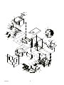
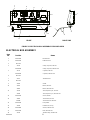
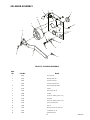
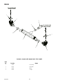
IMI CORNELIUS REMCOR INC g 500 REGENCY DRIVE g GLENDALE HEIGHTS, IL 60139--2268
Telephone (800) 551--4423
Facsimile (800) 519--4423
Operator’s Manual
ICE/BEVERAGE DISPENSER
Model: Enduro-150 8 Valve
IMPORTANT:
TO THE INSTALLER.
It is the responsibility of
the Installer to ensure that
the water supply to the
dispensing equipment is
provided with protection
against backflow by an air
gap as defined in
ANSI/ASME A112.1.2-1979;
or an approved vacuum
breaker or other such
method as proved effective
by test.
Water pipe connections
and fixtures directly
connected to a potable
water supply shall be
sized, installed, and
maintained according to
Federal, State, and Local
Codes.
Part No. 620904402
February, 1997
Revised: August, 2000
Revision C
THIS DOCUMENT CONTAINS IMPORTANT INFORMATION
This Manual must be read and understood before installing or operating this equipment
Ó IMI CORNELIUS INC; 1997-2000
PRINTED IN U.S.A
TABLE OF CONTENTS
Page
MAINTENANCE . . . . . . . . . . . . . . . . . . . . . . . . . . . . . . . . . . . . . . . . . . . . . . . . . . . . . . . . . . .
1
DAILY (OR AS REQUIRED) . . . . . . . . . . . . . . . . . . . . . . . . . . . . . . . . . . . . . . . . . . . . .
WEEKLY (OR AS REQUIRED) . . . . . . . . . . . . . . . . . . . . . . . . . . . . . . . . . . . . . . . . . .
1
1
MONTHLY . . . . . . . . . . . . . . . . . . . . . . . . . . . . . . . . . . . . . . . . . . . . . . . . . . . . . . . . . . . .
START-UP & OPERATING INSTRUCTIONS . . . . . . . . . . . . . . . . . . . . . . . . . . . . . . . . . .
1
1
CLEANING INSTRUCTIONS . . . . . . . . . . . . . . . . . . . . . . . . . . . . . . . . . . . . . . . . . . . . . . . .
1
DISPENSER . . . . . . . . . . . . . . . . . . . . . . . . . . . . . . . . . . . . . . . . . . . . . . . . . . . . . . . . . .
BEVERAGE SYSTEM (IF APPLICABLE) . . . . . . . . . . . . . . . . . . . . . . . . . . . . . . . . .
TROUBLESHOOTING . . . . . . . . . . . . . . . . . . . . . . . . . . . . . . . . . . . . . . . . . . . . . . . . . . . . . .
1
2
5
BLOWN FUSE OR CIRCUIT BREAKER. . . . . . . . . . . . . . . . . . . . . . . . . . . . . . . . . . .
5
GATE DOES NOT OPEN. AGITATOR DOES NOT TURN. . . . . . . . . . . . . . . . . . .
GATE DOES NOT OPEN OR IS SLUGGISH. AGITATOR TURNS. . . . . . . . . . .
ICE DISPENSES CONTINUOUSLY. . . . . . . . . . . . . . . . . . . . . . . . . . . . . . . . . . . . . . .
SLUSHY ICE. WATER IN HOPPER. . . . . . . . . . . . . . . . . . . . . . . . . . . . . . . . . . . . . .
BEVERAGES DO NOT DISPENSE. . . . . . . . . . . . . . . . . . . . . . . . . . . . . . . . . . . . . . .
BEVERAGES TOO SWEET. . . . . . . . . . . . . . . . . . . . . . . . . . . . . . . . . . . . . . . . . . . . .
BEVERAGES NOT SWEET ENOUGH. . . . . . . . . . . . . . . . . . . . . . . . . . . . . . . . . . . .
5
5
5
5
5
5
6
BEVERAGES NOT COLD (UNITS WITH BUILT-IN COLD PLATE). . . . . . . . . . . .
PARTS LIST / EXPLODED VIEW . . . . . . . . . . . . . . . . . . . . . . . . . . . . . . . . . . . . . . . . . . . .
6
7
CABINET SECTION PARTS LIST . . . . . . . . . . . . . . . . . . . . . . . . . . . . . . . . . . . . . . .
CABINET SECTION PARTS LIST (CONT’D) . . . . . . . . . . . . . . . . . . . . . . . . . . . . . .
CABINET SECTION PARTS LIST (CONT’D) . . . . . . . . . . . . . . . . . . . . . . . . . . . . . .
ELECTRICAL BOX ASSEMBLY . . . . . . . . . . . . . . . . . . . . . . . . . . . . . . . . . . . . . . . . .
SOLENOID ASSEMBLY . . . . . . . . . . . . . . . . . . . . . . . . . . . . . . . . . . . . . . . . . . . . . . . .
9
10
11
12
13
COLD PLATE DRAIN FOR Z STYLE UNITS . . . . . . . . . . . . . . . . . . . . . . . . . . . . . . .
WARRANTY . . . . . . . . . . . . . . . . . . . . . . . . . . . . . . . . . . . . . . . . . . . . . . . . . . . . . . . . . . . . . .
14
15
LIST OF FIGURES
Page
FIGURE 1. CABINET SECTION EXPLODED VIEW . . . . . . . . . . . . . . . . . . . . . . . .
FIGURE 2. ELECTRICAL BOX ASSEMBLY . . . . . . . . . . . . . . . . . . . . . . . . . . . . . . .
8
12
FIGURE 3. SOLENOID ASSEMBLY . . . . . . . . . . . . . . . . . . . . . . . . . . . . . . . . . . . . . .
13
FIGURE 4. COLD PLATE DRAIN FOR Z STYLE UNITS . . . . . . . . . . . . . . . . . . . .
14
i
620904402
MAINTENANCE
The following dispenser maintenance should be performed at the intervals indicated:
DAILY (or as required)
Remove foreign material from vending area drip tray to prevent drain blockage.
WEEKLY (or as required)
Clean vending area. Check for proper water drainage from the vending area drip tray.
MONTHLY
Clean and sanitize the hopper interior and beverage system, if applicable (see CLEANING INSTRUCTIONS).
START-UP & OPERATING INSTRUCTIONS
Fill the hopper with ice. Dispense several large cups of ice (approximately 20 to 30 seconds total dispensing time)
to allow ice to fill the cold plate cabinet. Add ice to the hopper as necessary to refill and replace the lid. Allow 10 to
15 minutes for the cold plate to cool down. Repeat this procedure whenever the dispenser has run out of ice. Start
up the beverage system and adjust faucets to the proper brix. Contact your local syrup distributor for complete
information on the beverage system.
In normal operation, pushing the ice dispenser mechanism will cause ice to flow from the ice chute. Ice flow will
continue until the dispenser mechanism is released. Dispensing of any faucet will provide beverage of the appropriate flavor.
CAUTION: Use caution to avoid spilling ice when filling dispenser. Clean up immediately any
spilled ice from filling or operating the unit. To prevent contamination of ice, the lid must be
installed on the unit at all times.
If the dispenser fails to dispense ice or beverage see troubleshooting guide.
CLEANING INSTRUCTIONS
WARNING: Disconnect Power Before Cleaning! Do not use metal scrapers, sharp objects or
abrasives on the ice storage hopper, top cover and the agitator disk, as damage may result.
Do not use solvents or other cleaning agents, as they may attack the plastic material.
Soap solution - Use a mixture of mild detergent and warm (100 degrees F) potable water.
Sanitizing solution - Use 1/2 ounce of household bleach in 1 gallon of potable water. Preparing the sanitizing
solution to this ratio will create a solution of 200 PPM.
DISPENSER
1. CLEANING EXTERIOR SURFACES
Important: Perform the following daily.
A.
Remove the cup rest from drip tray.
B.
Wash the drip tray with soap solution. Rinse with clean water and allow solution to run down the drain.
1
620904402
C.
Wash cup rest with soap solution and rinse in clean water. Install the cup rest into the drip tray.
D.
Clean all exterior surfaces with soap solution and rinse in clean water.
2. CLEANING INTERIOR SURFACES
CAUTION: When pouring liquid into the hopper, do not exceed the rate of 1/2 gallon
per minute.
Important: Perform the following at least once a month.
A.
Remove agitator assembly.
B.
Using a nylon bristle brush or sponge, clean the interior of the hopper, top cover and agitator assembly
with soap solution. Thoroughly rinse the hopper, cover and agitator surfaces with clean potable water.
C.
Reassemble agitator assembly. Take special care to ensure that the thumbscrew is tight.
D.
Using a mechanical spray bottle filled with sanitizing solution, spray the entire interior and agitator assembly. Allow to air dry.
E.
Remove merchandiser and ice chute cover from unit.
F.
With a nylon bristle brush or sponge, clean the inside of the ice chute, gasket, and cover with soap solution and rinse thoroughly to remove all traces of detergent.
G.
Reassemble ice chute assembly.
H.
Using a mechanical spray bottle filled with sanitizing solution, spray the inside of the ice chute. Allow to
air dry.
I.
Reinstall merchandiser.
BEVERAGE SYSTEM
(IF APPLICABLE)
WARNING: Disconnect Power Before Cleaning! Do not use metal scrapers, sharp objects
or abrasives on the ice storage hopper, top cover and the agitator disk, as damage may
result. Do not use solvents or other cleaning agents, as they may attack the plastic material.
Soap solution - Use a mixture of mild detergent and warm (100 degrees F) potable water.
Sanitizing solution - Use 1/2 ounce of household bleach in 1 gallon of potable water. Preparing the sanitizing
solution to this ratio, the required solution of 200 PPM will be obtained.
Cleaning tank - Fill clean, empty tank with a mixture of mild detergent and five (5) gallons of warm
potable water (120 degrees F).
CAUTION: When pouring liquid into the hopper, do not exceed the rate of 1/2 gallon
per minute.
1. COLD PLATE
A.
Remove splash panel.
B.
Remove or move the plastic cold plate cover to expose the cold plate.
C.
Locate and remove any debris from the drain trough. Check that the drain holes are not clogged.
D.
Pour small amount of soap solution through cold plate openings in hopper.
620904402
2
E.
Using a cloth, wash down the surfaces of the cold plate and plastic cover with soap solution.
F.
Install and properly position the cover on the cold plate.
G.
Install the splash panel in the reverse order it was removed.
H.
Rinse cold plate surface by pouring potable water through hopper openings.
2. DISPENSING VALVES
Refer to addendum supplied with the unit that is applicable to the manufacturer of the valves installed
on the unit.
3. PRODUCT TUBING
Only trained and qualified persons should perform these cleaning and sanitizing procedures.
A.
B.
Sanitize tank systems, Post-Mix and Pre-Mix
a.
Remove all the quick disconnects from all the tanks. Fill a suitable pail or bucket with
soap solution.
b.
Submerge all disconnects (gas and liquid) in the soap solution and then clean them using a nylon
bristle brush. (Do not use a wire brush). Rinse with clean water.
c.
Prepare sanitizing solution and using a mechanical spray bottle, spray the disconnects.
Allow to air dry.
d.
Using a clean, empty tank, prepare five (5) gallons of the sanitizing solution. Rinse the tank disconnects with approximately 9 oz. of the sanitizing solution. Close the tank.
e.
Prepare cleaning tank by filling clean five (5) gallon tank with a mixture of mild detergent and potable water (120_ F).
f.
Connect a gas disconnect to the tank and then apply one of the product tubes to the cleaning tank.
Operate the appropriate valve until liquid dispensed is free of any syrup.
g.
Disconnect cleaning tank and hook up sanitizing tank to syrup line and CO2 system.
h.
Energize beverage faucet until chlorine sanitizing solution is dispensed through the faucet. Flush
at least two (2) cups of liquid to ensure that the sanitizing solution has filled the entire length of the
syrup tubing.
i.
Allow sanitizer to remain in lines for fifteen (15) minutes.
j.
Repeat the step above, applying a different product tube each time until all tubes are filled with the
sanitizing solution.
k.
For post-mix valves, remove the nozzle and syrup diffuser and clean them in a mild soap solution.
Rinse with clean water and reassemble the nozzle and syrup diffuser to the valve.
l.
For pre-mix valves, disconnect all product tubes from the tank of sanitizing solution and then open
the valves to allow the pressure to be relieved. Remove the valves from the dispenser, disassemble and wash thoroughly in a mild soap solution.
m.
Rinse the parts in clean water, reassemble the valve and reconnect it to the dispenser.
n.
Discard the tank of sanitizing solution and reconnect the product (syrup or pre-mix) tanks. Operate
the valves until all sanitizer has been flushed from the system and only product (syrup or pre-mix)
is flowing.
Sanitize syrup lines, B-I-B Systems
a.
Remove all the quick disconnects from all the B-I-B containers.
b.
Fill a suitable pail or bucket with soap solution.
3
620904402
c.
Submerge all disconnects (gas and liquid) in the soap solution and then clean them using a nylon
bristle brush. (Do not use a wire brush). Rinse with clean water.
d.
Using a plastic pail, prepare approximately five (5) gallons of sanitizing solution.
e.
Rinse the B-I-B disconnects in the sanitizing solution.
f.
Sanitizing fittings must be attached to each B-I-B disconnect. If these fittings are not available, the
fittings from empty B-I-B bags can be cut from the bags and used. These fittings open the disconnect so the sanitizing solution can be drawn through the disconnect.
g.
Place all the B-I-B disconnects into the pail of sanitizing solution. Operate all the valves until the
sanitizing solution is flowing from the valve. Allow sanitizer to remain in lines for fifteen
(15) minutes.
h.
Remove the nozzle and syrup diffuser from each valve and clean them in a soap solution. Rinse
with clean water and reassemble the nozzle and syrup diffuser to the valve.
i.
Remove the sanitizing fittings from the B-I-B disconnects and connect the disconnects to the appropriate B-I-B container. Operate the valves until all sanitizer has been flushed from the system
and syrup is flowing freely.
620904402
4
TROUBLESHOOTING
IMPORTANT: Only qualified personnel should service internal components or electrical wiring.
WARNING: If repairs are to be made to a product system, remove quick disconnects from
the applicable product tank, then relieve the system pressure before proceeding. If repairs
are to be made to the CO2 system, stop dispensing, shut off the CO2 supply, then relieve the
system pressure before proceeding. If repairs are to be made to the refrigeration system, make sure
electrical power is disconnected from the unit.
Should your unit fail to operate properly, check that there is power to the unit and that the hopper contains ice. If the unit does not dispense, check the following chart under the appropriate symptoms to aid
in locating the defect.
Probable Cause
Trouble
BLOWN FUSE OR CIRCUIT BREAKER.
GATE DOES NOT OPEN. AGITATOR DOES
NOT TURN.
GATE DOES NOT OPEN OR IS SLUGGISH.
AGITATOR TURNS.
ICE DISPENSES CONTINUOUSLY.
SLUSHY ICE. WATER IN HOPPER.
BEVERAGES DO NOT DISPENSE.
BEVERAGES TOO SWEET.
5
A.
Short circuit in wiring.
B.
Defective gate solenoid.
C.
Defective agitator motor.
A.
No power.
B.
Bent depressor plate (does not actuate switch).
C.
Defective dispensing switch.
A.
Defective gate solenoid.
B.
Excessive pressure against gate slide.
C.
Defective rectifier.
A.
Stuck or bent depressor plate (does not
release switch).
B.
Defective dispensing switch.
C.
Improper switch installation.
A.
Blocked drain.
B.
Unit not level.
C.
Poor ice quality due to water quality or
icemaker problems.
D.
Improper use of flaked ice.
A.
No 24 volt power to faucets.
B.
No CO2 pressure.
A.
Carbonator not working.
B.
No CO2 pressure in carbonator.
C.
Faucet brix requires adjusting.
620904402
Trouble
Probable Cause
BEVERAGES NOT SWEET ENOUGH.
BEVERAGES NOT COLD (UNITS WITH BUILT-IN
COLD PLATE).
A.
Empty syrup tank.
B.
Faucet brix requires adjusting.
A.
Unit standing with no ice in hopper -- no ice in
cold plate cabinet.
Contact your local syrup or beverage equipment distributor for additional information and troubleshooting of beverage system.
620904402
6
PARTS LIST / EXPLODED VIEW
7
620904402
19
52
57
5
87
96
1
26
68
32
63
80
46 2
94
79
66
69
4
44
50
74
48
62
67
64
39
91
92
81
49
56
90
25
74
30
21
94
6
51
72
24
61
10
54
72
88
60
73
74
72
17
72
58
76
71
75 53
88
7
76
95
84
34
86
13
14
22
70
77
12
93
88
15
72
59
47
8
85
55
23
83
620904402
8
16
CABINET SECTION PARTS LIST
Index
No.
Part No.
1
21491
2
22081R
3
Not Used
4
**29303R
5
15346
6
620021201
Cover, Rear Wrapper
7
629080213
Lower Panel Assy (For Drip Tray)
629080215
Lower Panel Assy (Z Model)
8
620020101
Sink Extension Assy, Drip Tray
9
Not Used
10
620020001
11
Not Used
12
Contact Sales
Panel Cold Plate/Faucet Assy
13
27107
Retainer Lever, Ice Dispenser
14
10145
Pin Sink Ext.
15
31007
Switch Boot
16
50335
Insulation, Cold Plate Drain
17
50767
Heyco Snap Bushing
18
Not Used
19
15087
20
Not Used
21
30794
Motor Heater, 115 Volt
32826
Motor Heater, 220-240 Volt
22
30895
Dispense Switch
23
53011
Elbow Cold Plate Drain
24
31622
Bulb-Daylight 18”
25
**620307901
Agitator Motor, 120 Volt
**620307902
Agitator Motor, 220-240 Volt
32954
Solenoid Assembly, 115 Volt
33409
Solenoid Assembly, 220-240 Volt
26
Name
Gate Slide
Gate Restrictor
Plate, Motor Mounting
Agitator Assy
Wrapper
Retainer, Agitator
27
Not Used
28
Not Used
29
Not Used
30
620302001
Electrical Box Assy, 120 Volt (B & BC Models)
620303301
Electrical Box Assy, 120 Volt (Ice Only)
620302301
Electrical Box Assy, 220-240 Volt (B & BC Models)
620303302
Electrical Box Assy, 220-240 Volt (Ice Only)
31
Not Used
32
620022201
33
Not Used
34
71010
Bracket, Motor Mounting
Washer, No. 8
9
620904402
CABINET SECTION PARTS LIST (CONT’D)
35
Not Used
36
Not Used
37
Not Used
38
Not Used
39
620019701
40
Not Used
41
Not Used
42
Not Used
43
Not Used
44
**51859
45
Not Used
46
51891
47
***51908
Plug (120V Models Only)
48
**52876
Gasket, Motor Shaft
49
620500901
50
53168
Ice Chute Cover
51
53241
Access Cover (Cold Plate Models Only)
52
53227
Agitator Disk
53
Contact Sales
Merchandiser, Black
Contact Sales
Merchandiser, Gray
620024118
Merchandiser, S.S.
620024117
Merchandiser, S.S. (For Lid and Straw Holder)
620024116
Merchandiser, S.S. (For Medallion)
620024115
Merchandiser, S.S. (For Low Ice Light)
54
620502801
Lens, Merchandiser
55
620502701
Foamed Sink Assy, Black
620502702
Foamed Sink Assy, Gray
56
Hinge, Gusset
Seal, Agitator Motor Shaft
Gasket, Gate
Ice Chute
52879
Lid, Dispenser, Black
53019
Lid, Dispenser, Gray
57
52872
Hopper Assy
58
620021901
59
52967
Plug, Plastic
60
52972
Tab Retaining
61
53236
Cover (Cold Plate Models Only)
62
70016
Hex Nut, No. 10-32 S.S.
63
70017
Hex Nut, No. 10-32 Nylon Insert Locknut
64
**70018
65
Not Used
66
**70048
67
70056
620904402
Baffle
Hex Nut, 1/4-20 Keps
Washer, .255 I.D.
Washer, No. 10, .219 I.D.
10
CABINET SECTION PARTS LIST (CONT’D)
68
70067
Washer, .218 I.D.
69
70076
Hex Nut, No. 8-32
70
70104
Nutsert No. 8-32
71
Contact Sales
72
70171
Machine Screw, Phil Truss Hd, No. 8-32 By 3/8-In. Long
73
70178
Machine Screw, Phil Truss Hd, No. 8-32 By 1/2-In. Long
74
70204
Sheet Metal Screw, Phil Truss Hd, No. 8 By 1/2-In. Long
75
620503401
Spacer, Cabinet
76
51334
Adhesive Tape
77
15500
Dispense Lever, Short (Cup Activated)
15488
Dispense Lever, Long (Cup Activated)
15501
Push Lever (Ice Dispense)
Graphics
78
Not Used
79
70260
Machine Screw, Phil Rd Hd, 1/4-20 By 1-In. Long
80
70320
Pop Rivet, 1/8
81
70341
Spring, Hopper Gate Slide
82
620701601
83
70478R
84
70555
Machine Screw, Phil Truss Hd, No. 8-32 By 3 1/4-In. Long
85
70750
Hose Clamp, Worn
86
71006
Machine Screw, Phil Truss Hd, No. 8-32 By 2 1/4-In. Long
87
53299
Clip, Black
88
70959
Hex Nutsert, No. 8-32
89
70970
Leg, Black
90
70992
Receptacle, 1/4 Turn
91
**70993
Retainer, 1/4 Turn
92
**70994
Stud Wing Hd, 1/4 Turn
93
70847
Spacer, Dispense Switch
94
70456
3/16 Pop Rivet
95
620700301
96
71089
Shoulder Screw, No. 8-32
*97
51288
Adapter, 1”Barb x 3/4 M.P.T. (For Drip Tray Drain)
*98
50952
Adapter, 3/4 soc x 3/4 F.P.T. (For Drip Tray Drain)
*99
620702201
NOTES:
Thread Forming Screw, Phil Pan hd, No. 10-16 By 1/2-In. Long
Clip, Push On
Cup Rest
Cold Plate Cleaning Brush
*NOT SHOWN
**PARTS INCLUDED IN AGITATOR MOTOR KIT.
***FOR 220-240V MODELS, 51908 PLUG REPLACED BY 620303001
PUSH-BUTTON SWITCH ACTUATOR AND 620303002 SWITCH BLOCK.
11
620904402
5
4
11
17
7
NC
NO
COM
L2
NO
L1
NC
COM
1
13
15
16
2
9
12
18
10
14
FRONT
RIGHT SIDE
FIGURE 2. ELECTRICAL BOX ASSEMBLY EXPLODED VIEW
ELECTRICAL BOX ASSEMBLY
Item
No.
Part No.
1
620019001
Electrical Box
2
620019101
Reflector Panel
3
Not Used
4
30514
620308102
5
30774
620308101
Name
Clamp, Capacitor, 120 Volt
Clamp, Capacitor, 220-240 Volt
Capacitor, 120 Volt
Capacitor, 220-240 Volt
6
Not Used
7
31107
8
Not Used
9
31620
Starter
10
31621
Ballast, 120 Volt
33662
Ballast, 220-240 Volt
31763
Timer, Repeat Cycle, 120 Volt
32828
Timer, Repear Cycle, 220-240 Volt
11
12
620302201
13
32682
32829R
Terminal Board
Socket, Starter
Transformer, 120 Volt
Transformer, 220-240 Volt
14
620302101
15
32958
Rectifier, 10A,. Body
16
620304601
Varistor, 220-240 Volt
17
620307301
Filter, 220-240 Volt
18
32244
620904402
Lamp-holder
Termiinal Strip, 220-240 Volt
12
SOLENOID ASSEMBLY
9
4
11
5
14
3
6
15
5
12
10
8
7
13
1
2
FIGURE 3. SOLENOID ASSEMBLY
Item
No.
Part No.
1
28173
Arm, Gate Lift
2
50754
Bearing, Gate Arm
3
32957
Solenoid, 120 Volt
33397
Solenoid, 220-240 Volt
4
28172
Plate, Solenoid Mounting
5
50752
Isolator
6
70015
Hex Nut, No. 10-32
7
51689
Locktite
8
70162
Screw, No. 8-32 By 1/4-In. Long
9
50705
Tie Cable
10
70165
Screw, No. 8-32 By 5/8-In. Long
11
71007
Spring, Solenoid Arm
12
51348
Spacer
13
70067
Washer, .218 I.D. By .875 O.D.
14
70057
Lockwasher, No. 10
15
70052
Name
Flatwasher, No. 8
13
620904402
DRAIN
TO COLD PLATE
DRAIN ELBOW
1
3
4
1
TO COLD PLATE
DRAIN ELBOW
1
1
2
1
3
FIGURE 4. COLD PLATE DRAIN FOR Z STYLE UNITS
Item
No.
Part No.
1
70750
Hose Clamp
2
53170
Drain Tube
3
51280
Elbow
4
53293
Coupler
620904402
Name
14
IMI CORNELIUS INC.
ONE CORNELIUS PLACE
ANOKA, MN. 55303--6234
TELEPHONE (800) 238--3600
FACSIMILE (612) 422--3232
WARRANTY
IMI Cornelius Inc. and Remcor Products Company warrant that all equipment and parts are free from defects in
material and workmanship under normal use and service. For a copy of the warranty applicable to your
Cornelius and or Remcor product, in your country, please write, fax or telephone the IMI Cornelius office nearest you. Please provide the equipment model number and the date of purchase.
IMI Cornelius Offices
AUSTRALIA D P.O. 210, D RIVERWOOD, D NSW 2210, AUSTRALIA D (61) 2 533 3122 D FAX (61) 2 534 2166
AUSTRIA D AM LANGEN FELDE 32 D A-1222 D VIENNA, AUSTRIA D (43) 1 233 520 D FAX (43) 1-2335-2930
BELGIUM D BOSKAPELLEI 122 D B-2930 BRAASCHAAT, BELGIUM D (32) 3 664 0552 D FAX (32) 3 665 2307
BRAZIL D RUA ITAOCARA 97 D TOMAS COELHO D RIO DE JANEIRO, BRAZIL D (55) 21 591 7150 D FAX (55) 21 593 1829
ENGLAND D TYTHING ROAD ALCESTER D WARWICKSHIRE, B49 6 EU, ENGLAND D (44) 789 763 101 D FAX (44) 789 763 644
FRANCE D 71 ROUTE DE ST. DENIS D F-95170 DEUIL LA BARRE D PARIS, FRANCE D (33) 1 34 28 6200 D FAX (33) 1 34 28 6201
GERMANY D CARL LEVERKUS STRASSE 15 D D-4018 LANGENFELD, GERMANY D (49) 2173 7930 D FAX (49) 2173 77 438
GREECE D 488 MESSOGION AVENUE D AGIA PARASKEVI D 153 42 D ATHENS, GREECE D (30) 1 600 1073 D FAX (30) 1 601 2491
HONG KONG D 1104 TAIKOTSUI CENTRE D 11-15 KOK CHEUNG ST D TAIKOKTSUE, HONG KONG D (852) 789 9882 D FAX (852) 391 6222
ITALY D VIA PELLIZZARI 11 D 1-20059 D VIMARCATE, ITALY D (39) 39 608 0817 D FAX (39) 39 608 0814
NEW ZEALAND D 20 LANSFORD CRES. D P.O. BOX 19-044 AVONDALE D AUCKLAND 7, NEW ZEALAND D (64) 9 8200 357 D FAX (64) 9 8200 361
SINGAPORE D 16 TUAS STREET D SINGAPORE 2263 D (65) 862 5542 D FAX (65) 862 5604
SPAIN D POLIGONO INDUSTRAIL D RIERA DEL FONOLLAR D E-08830 SANT BOI DE LLOBREGAT D BARCELONA, SPAIN D (34) 3 640 2839 D FAX (34) 3 654 3379
USA D ONE CORNELIUS PLACE D ANOKA, MINNESOTA D (612) 421-6120 D FAX (612) 422-3255
15
620904402
IMI CORNELIUS INC.
Corporate Headquarters:
One Cornelius Place
Anoka, Minnesota 55303-6234
(612) 421-6120
(800) 238-3600


![Service Manual VA13 Carbonator [ 002818 ]](http://vs1.manualzilla.com/store/data/006013608_1-0f8f87056a0ab013b1dd01dac3912d47-150x150.png)