1
Cisco CSR 1000V Series Cloud Services
Router Software Configuration Guide
Cisco IOS XE Release 3.9S, 3.10S, 3.11S, 3.12S
First Published: July 26, 2012
Last Updated: June 27, 2014
Cisco Systems, Inc.
www.cisco.com
Cisco has more than 200 offices worldwide.
Addresses, phone numbers, and fax numbers
are listed on the Cisco website at
www.cisco.com/go/offices.
Text Part Number: OL-27477-07
THE SPECIFICATIONS AND INFORMATION REGARDING THE PRODUCTS IN THIS MANUAL ARE SUBJECT TO CHANGE WITHOUT NOTICE. ALL
STATEMENTS, INFORMATION, AND RECOMMENDATIONS IN THIS MANUAL ARE BELIEVED TO BE ACCURATE BUT ARE PRESENTED WITHOUT
WARRANTY OF ANY KIND, EXPRESS OR IMPLIED. USERS MUST TAKE FULL RESPONSIBILITY FOR THEIR APPLICATION OF ANY PRODUCTS.
THE SOFTWARE LICENSE AND LIMITED WARRANTY FOR THE ACCOMPANYING PRODUCT ARE SET FORTH IN THE INFORMATION PACKET THAT
SHIPPED WITH THE PRODUCT AND ARE INCORPORATED HEREIN BY THIS REFERENCE. IF YOU ARE UNABLE TO LOCATE THE SOFTWARE LICENSE
OR LIMITED WARRANTY, CONTACT YOUR CISCO REPRESENTATIVE FOR A COPY.
The Cisco implementation of TCP header compression is an adaptation of a program developed by the University of California, Berkeley (UCB) as part of UCB’s public
domain version of the UNIX operating system. All rights reserved. Copyright © 1981, Regents of the University of California.
NOTWITHSTANDING ANY OTHER WARRANTY HEREIN, ALL DOCUMENT FILES AND SOFTWARE OF THESE SUPPLIERS ARE PROVIDED “AS IS” WITH
ALL FAULTS. CISCO AND THE ABOVE-NAMED SUPPLIERS DISCLAIM ALL WARRANTIES, EXPRESSED OR IMPLIED, INCLUDING, WITHOUT
LIMITATION, THOSE OF MERCHANTABILITY, FITNESS FOR A PARTICULAR PURPOSE AND NONINFRINGEMENT OR ARISING FROM A COURSE OF
DEALING, USAGE, OR TRADE PRACTICE.
IN NO EVENT SHALL CISCO OR ITS SUPPLIERS BE LIABLE FOR ANY INDIRECT, SPECIAL, CONSEQUENTIAL, OR INCIDENTAL DAMAGES, INCLUDING,
WITHOUT LIMITATION, LOST PROFITS OR LOSS OR DAMAGE TO DATA ARISING OUT OF THE USE OR INABILITY TO USE THIS MANUAL, EVEN IF CISCO
OR ITS SUPPLIERS HAVE BEEN ADVISED OF THE POSSIBILITY OF SUCH DAMAGES.
Cisco and the Cisco logo are trademarks or registered trademarks of Cisco and/or its affiliates in the U.S. and other countries. To view a list of Cisco trademarks, go to this
URL: www.cisco.com/go/trademarks. Third-party trademarks mentioned are the property of their respective owners. The use of the word partner does not imply a partnership
relationship between Cisco and any other company. (1110R)
Any Internet Protocol (IP) addresses and phone numbers used in this document are not intended to be actual addresses and phone numbers. Any examples, command display
output, network topology diagrams, and other figures included in the document are shown for illustrative purposes only. Any use of actual IP addresses or phone numbers in
illustrative content is unintentional and coincidental.
Cisco CSR 1000V Series Cloud Services Router Software Configuration Guide
Copyright © 2012–2014 Cisco Systems, Inc. All rights reserved.
CONTENTS
Preface
Objectives
v
Document Revision History
Organization
vi
vii
Related Documentation
viii
Document Conventions
viii
Obtaining Documentation and Submitting a Service Request
CHAPTER
1
Cisco CSR 1000V Series
Cloud Services Router Overview
ix
1-1
Introduction 1-1
Benefits of Virtualization Using the Cisco CSR 1000V Series Cloud Services Router
Software Configuration and Management Using the Cisco IOS XE CLI 1-2
Router Interfaces 1-3
Virtual Machine Requirements 1-4
Virtual Machines 1-4
Hypervisor Support 1-4
Hypervisor vNIC Requirements 1-5
Cisco CSR 1000V and Hypervisor Limitations
Server Requirements 1-8
Cisco CSR 1000V Series Software License Overview
1-7
1-8
Cisco CSR 1000V Series Architecture Differences from Hardware Platforms
Supported Cisco IOS XE Technologies
1-2
1-12
1-13
Management Support 1-20
Managing the Router Using Cisco Configuration Professional 1-20
Managing the Router Using the Cisco CSR 1000V REST API 1-20
Managing the Router Using Cisco Prime Network Services Controller
Related Cisco Product Compatibility 1-21
Cisco Unified Computing System (UCS) Products 1-21
Finding Support Information for Platforms and Cisco Software Images
Using Cisco Feature Navigator 1-22
Using the Software Advisor 1-22
1-20
1-22
Cisco CSR 1000V Series Cloud Services Router Software Configuration Guide
OL-27477-07
iii
Contents
Using the Software Release Notes
CHAPTER
2
Using Cisco IOS XE Software
Using Keyboard Shortcuts
1-22
2-1
2-1
Using the History Buffer to Recall Commands
Understanding the Command Modes
Getting Help 2-3
Finding Command Options
2-1
2-2
2-3
Using the no and default Forms of Commands
Saving Configuration Changes
2-6
2-6
Managing Configuration Files 2-7
NVRAM File Security 2-8
Filtering the Output of show and more Commands
Powering Off the Cisco CSR 1000V
CHAPTER
3
Installation Overview
Introduction
2-8
2-8
3-1
3-1
Obtaining the Cisco CSR 1000V Software 3-3
Cisco CSR 1000V Installation Files 3-3
Cisco CSR 1000V Installation Options 3-3
Guidelines and Limitations 3-4
ROMMON and the Cisco CSR 1000V 3-5
Where to Go Next
CHAPTER
4
3-5
Installing the Cisco CSR 1000V in VMware ESXi Environments
VMware ESXi Support Information 4-1
Supported VMware Features and Operations
Installation Requirements for VMware ESXi
4-1
4-4
4-9
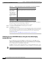
Deploying the Cisco CSR 1000V OVA Template to the VM 4-10
Deploying the OVA Template to the VM 4-10
Deploying the Cisco CSR 1000V Software Using the Cisco Build, Deploy, Execute OVF Tool
Editing the Cisco CSR 1000V Basic Properties Using the vSphere GUI 4-17
Adding Custom Properties for the Cisco CSR 1000V 4-19
4-14
Manually Creating the VM and Installing the Cisco CSR 1000V Software Using the .iso File (VMware
ESXi) 4-21
Overview of Tasks for Manually Creating the Cisco CSR 1000V VM 4-21
Manually Creating the Cisco CSR 1000V VM Using the .iso File (VMware ESXi) 4-23
Increasing Performance on VMWare ESXi Configurations
4-25
Cisco CSR 1000V Series Cloud Services Router Software Configuration Guide
iv
OL-27477-07
Contents
CHAPTER
5
Installing the Cisco CSR 1000V in
Citrix XenServer Environments 5-1
Citrix XenServer Support Information
5-1
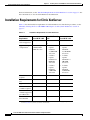
Installation Requirements for Citrix XenServer
5-2
Manually Creating the Cisco CSR 1000V VM Using the .iso File (Citrix XenServer)
5-3
5-4
CHAPTER
6
Installing the Cisco CSR 1000V in KVM Environments
Kernel Virtual Machine Support Information
KVM Support on OpenStack 6-1
Installation Requirements for KVM
6-1
6-1
6-2
Manually Creating the Cisco CSR 1000V VM Using the .iso File (KVM)
6-3
Creating the Cisco CSR 1000V KVM Instance on OpenStack Using the .qcow2 File
Creating the Instance Using the KVM Command 6-5
Creating the Instance Using the OpenStack Command Line Tool 6-6
Creating the Instance Using the OpenStack Dashboard 6-7
Increasing Performance on KVM Configurations
CHAPTER
7
6-8
Installing the Cisco CSR 1000V in Microsoft Hyper-V Environments
Microsoft Hyper-V Support Information
7-1
7-1
Installation Requirements for Microsoft Hyper-V
7-2
Manually Creating the Cisco CSR 1000V VM Using the .iso File (Microsoft Hyper-V)
Prerequisites 7-3
Configuring the Server Manager Settings 7-3
Creating the VM 7-3
Configuring the VM Settings 7-4
Launching the VM to Boot the Cisco CSR 1000V 7-6
CHAPTER
8
Booting the Cisco CSR 1000V and Accessing the Console
Booting the Cisco CSR 1000V as the VM
6-5
7-2
8-1
8-1
Accessing the Cisco CSR 1000V Console 8-3
Accessing the Cisco CSR 1000V Through the VM Console 8-3
Accessing the Cisco CSR 1000V Through the Virtual Serial Port 8-3
Creating Serial Console Access in VMware ESXi 8-4
Creating the Serial Console Access in KVM 8-5
Creating the Serial Console Access in Microsoft Hyper-V 8-5
Opening a Telnet Session to the Cisco CSR 1000V Console on the Virtual Serial Port
Changing the Console Port Access After Installation 8-6
8-5
Cisco CSR 1000V Series Cloud Services Router Software Configuration Guide
OL-27477-07
v
Contents
CHAPTER
9
Upgrading the Cisco IOS XE Software
9-1
Prerequisites for the Software Upgrade Process 9-1
Saving Backup Copies of Your Old System Image and Configuration
9-2
Using TFTP or Remote Copy Protocol to Copy the System Image into Boot Flash Memory
Loading the New System Image 9-5
Loading the New System Image from the Cisco IOS XE Software
Loading the New System Image from GRUB Mode 9-8
9-5
Saving Backup Copies of Your New System Image and Configuration
9-9
Rebooting the Cisco CSR 1000V
CHAPTER
10
9-4
9-11
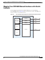
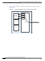
Mapping Cisco CSR 1000V Network Interfaces to VM Network Interfaces
10-1
Mapping the Router Network Interfaces to Virtual Network Interface Cards 10-1
Adding and Deleting Network Interfaces on the Cisco CSR 1000V 10-3
Cisco CSR 1000V Network Interfaces and VM Cloning 10-4
Mapping Cisco CSR 1000V Network Interfaces with vSwitch Interfaces
CHAPTER
11
Accessing and Using GRUB Mode
11-1
About GRUB Mode and the Configuration Register
Accessing GRUB Mode
11-2
Using the GRUB Menu
11-3
Modifying the Configuration Register (confreg)
Changing the Configuration Register Settings
12
11-6
Configuring Call Home for the Cisco CSR 1000V
Prerequisites for Call Home
11-1
11-3
Displaying the Configuration Register Settings
CHAPTER
10-5
11-6
12-1
12-1
Information About Call Home 12-2
Benefits of Using Call Home 12-2
Obtaining Smart Call Home Services
Anonymous Reporting 12-3
12-3
How to Configure Call Home 12-4
Configuring Smart Call Home (Single Command) 12-4
Configuring and Enabling Smart Call Home 12-6
Enabling and Disabling Call Home 12-6
Configuring Contact Information 12-7
Example 12-8
Configuring Destination Profiles 12-8
Cisco CSR 1000V Series Cloud Services Router Software Configuration Guide
vi
OL-27477-07
Contents
Creating a New Destination Profile 12-9
Copying a Destination Profile 12-11
Setting Profiles to Anonymous Mode 12-12
Subscribing to Alert Groups 12-13
Periodic Notification 12-15
Message Severity Threshold 12-16
Configuring Snapshot Command List 12-17
Configuring General email Options 12-18
Example 12-20
Specifying Rate Limit for Sending Call Home Messages 12-20
Specifying HTTP Proxy Server 12-21
Enabling AAA Authorization to Run IOS Commands for Call Home Messages 12-22
Configuring Syslog Throttling 12-23
Configuring Call Home Data Privacy 12-24
Sending Call Home Communications Manually 12-25
Sending a Call Home Test Message Manually 12-25
Sending Call Home Alert Group Messages Manually 12-26
Submitting Call Home Analysis and Report Requests 12-27
Manually Sending Command Output Message for One Command or a Command List
Configuring Diagnostic Signatures 12-30
Prerequisites for Diagnostic Signatures 12-30
Information About Diagnostic Signatures 12-30
Diagnostic Signatures Overview 12-31
Diagnostic Signature Downloading 12-31
Diagnostic Signature Workflow 12-32
Diagnostic Signature Events and Actions 12-32
Diagnostic Signature Event Detection 12-32
Diagnostic Signature Actions 12-33
Diagnostic Signature Variables 12-33
How to Configure Diagnostic Signatures 12-34
Configuring the Call Home Service for Diagnostic Signatures
Configuring Diagnostic Signatures 12-36
Configuration Examples for Diagnostic Signatures 12-37
Displaying Call Home Configuration Information
Examples 12-39
Default Settings
12-28
12-34
12-38
12-44
Alert Group Trigger Events and Commands
12-44
Message Contents 12-45
Sample Syslog Alert Notification in XML Format
12-48
Cisco CSR 1000V Series Cloud Services Router Software Configuration Guide
OL-27477-07
vii
Contents
CHAPTER
13
Managing Cisco CSR 1000V Licenses
13-1
Activating Cisco CSR 1000V Licenses
13-1
Managing Technology Package and Throughput Licenses 13-1
License Upgrade and Downgrade Scenarios 13-2
Changing the Technology Package License Boot Level (Cisco IOS XE Release 3.10S and Later)
Managing the Throughput Level Licenses 13-3
Changing the Maximum Throughput Level 13-4
License-Based Restriction on Aggregate Bandwidth 13-6
Managing Memory Upgrade Licenses (Cisco IOS XE Release 3.11S and Later) 13-7
Requesting a New Virtual UDI 13-8
CHAPTER
14
Configuring Support for Management Using the REST API
Introduction
14-1
14-1
Enabling REST API Support During Cisco CSR 1000V OVA Deployment
14-1
Enabling REST API Support Using the Cisco IOS XE CLI 14-3
Configuring the Management Interface to Support the REST API
(Cisco IOS XE Release 3.11S and Later) 14-3
Configuring HTTPS Support for the REST API Using the Cisco IOS XE CLI
Disabling REST API Support 14-7
Viewing the REST API Container Status 14-8
CHAPTER
15
13-2
14-6
Configuring Support for Remote Management by the Cisco Prime Network Services
Controller 15-1
Configuring the Management Interface to Support Remote Management by the Cisco Prime Network
Services Controller 15-1
Configuring Remote Management by Cisco Prime Network Services Controller 15-4
Enabling Remote Management by the Cisco Prime Network Services Controller Host 15-4
Disabling Remote Management by the Cisco Prime Network Services Controller Host 15-6
CHAPTER
16
Troubleshooting Cisco CSR 1000V VM Issues
16-1
Verifying the Cisco CSR 1000V Hardware and VM Requirements
Troubleshooting Network Connectivity Issues
Troubleshooting VM Performance Issues
APPENDIX
A
Rehosting the Cisco CSR 1000V License
16-1
16-2
16-2
A-1
Voluntarily Rehosting the License to a New VM
Obtaining a Rehost License if the System Fails
A-1
A-4
INDEX
Cisco CSR 1000V Series Cloud Services Router Software Configuration Guide
viii
OL-27477-07
Preface
This preface describes the objectives and organization of this document and explains how to find
additional information on related products and services. This preface contains the following sections:
•
Objectives, page v
•
Document Revision History, page vi
•
Organization, page vii
•
Related Documentation, page viii
•
Document Conventions, page viii
•
Obtaining Documentation and Submitting a Service Request, page ix
Objectives
This document provides an overview of software functionality that is specific to the Cisco CSR 1000V
Series Cloud Services Router. It is not intended as a comprehensive guide to all of the software features
that can be run using the Cisco CSR 1000V Series router, but only the software aspects that are specific
to this router.
For information on general software features that are also available on the Cisco CSR 1000V Series
router, see the Cisco IOS XE technology guides for that specific software feature.
Cisco CSR 1000V Series Cloud Services Router Software Configuration Guide
OL-27477-07
v
Preface
Document Revision History
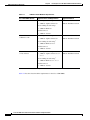
The Document Revision History records technical changes to this document. The table shows the
Cisco IOS XE software release number, the date of the change, and a brief summary of the change
Release
Date
Cisco IOS XE
Release 3.9S
April 1, 2013
Cisco IOS XE
Release 3.10S
Cisco IOS XE
Release 3.11S
Cisco IOS XE
Release 3.12S
July 30, 2013
November 21, 2013
March 28, 2014
Change Summary
•
Updates to Cisco IOS technology features
supported
•
Support for throughput-based licenses
•
Support for the Cisco Build, Deploy, Execute
OVF (BDEO) tool
•
Support for the VMXNET3 vNIC interface
type
•
Support for updating properties using the
vSphere GUI
•
Support for VMware ESXi 5.1
•
Support for the Citrix XenServer, version
6.0.2 hypervisor
•
Support for the Kernel Virtual Machine
(KVM) hypervisor
•
Support for technology-based licenses
•
Support for 1vCPU and 4vCPU
configurations (VMware ESXi only)
•
Initial support of REST API for selected
features
•
Removal of the GigabitEthernet 0 interface
•
Support added for 2 vCPU configurations
(VMware ESXi only)
•
Support added for 1vCPU and 4vCPU
configurations (Citrix XenServer and KVM)
•
Support for KVM using OpenStack
•
Support for VXLAN termination
•
Support for deploying the Cisco CSR 1000V
on Amazon Web Services
•
Support for additional REST APIs
•
Support for managing the router remotely
using Cisco Prime Network Services
Controller (PNSC)
•
Support for the Microsoft Hyper-V
hypervisor
•
Support for Cisco Call Home and Cisco Smart
Call Home
•
Support for additional REST APIs
Cisco CSR 1000V Series Cloud Services Router Software Configuration Guide
vi
OL-27477-07
Preface
Organization
Chapter
Title
Description
Chapter 1
“Cisco CSR 1000V Series Cloud
Services Router Overview”
Provides an overview of the Cisco CSR 1000V
Series Cloud Services Router.
Chapter 2
“Using Cisco IOS XE Software”
Provides an overview of Cisco IOS XE software.
Chapter 3
“Installation Overview”
Provides information on the Cisco CSR 1000V
installation options.
Chapter 4
“Installing the Cisco CSR 1000V in Describes how to install the Cisco CSR 1000V on
VMware ESXi Environments”
a VMware ESXi VM.
Chapter 5
“Installing the Cisco CSR 1000V in
Citrix XenServer Environments”
Chapter 6
“Installing the Cisco CSR 1000V in Describes how to install the Cisco CSR 1000V on
KVM Environments”
a Kernel Virtual Machine (KVM).
Chapter 7
“Installing the Cisco CSR 1000V in Describes how to install the Cisco CSR 1000V on
Microsoft Hyper-V Environments” a Microsoft Hyper-V VM.
Chapter 8
“Booting the Cisco CSR 1000V and Describes how to boot the Cisco CSR 1000V and
Accessing the Console”
access the console.
Chapter 9
“Upgrading the Cisco IOS XE
Software”
Chapter 10
Provides information on how to map the
“Mapping Cisco CSR 1000V
Network Interfaces to VM Network Cisco CSR 1000V router interfaces to the VM
Interfaces”
network interfaces.
Chapter 11
“Accessing and Using GRUB
Mode”
Describes how to access the GRUB interface and
how to change the configuration register settings.
Chapter 12
“Configuring Call Home for the
Cisco CSR 1000V”
Describes how to configure Call Home and Smart
Call Home.
Chapter 13
“Managing Cisco CSR 1000V
Licenses”
Provides information on managing software
licenses for the Cisco CSR 1000V.
Chapter 14
“Configuring Support for Manage- Provides information on how to configure the
ment Using the REST API”
Cisco CSR 1000V to enable management of the
router using the REST API.
Chapter 15
“Configuring Support for Remote
Management by the Cisco Prime
Network Services Controller”
Provides information on how to activate support for
Cisco Prime Network Services Controller (PNSC),
a GUI-based network management tool that can be
used to manage and provision the
Cisco CSR 1000V.
Chapter 16
“Troubleshooting Cisco CSR
1000V VM Issues”
Provides information on how to troubleshoot issues
related to VM and router performance.
Appendix A “Rehosting the Cisco CSR 1000V
License”
Describes how to install the Cisco CSR 1000V on
a Citrix XenServer VM.
Describes how to upgrade the Cisco IOS XE
software on the Cisco CSR 1000V.
Provides information on rehosting the
Cisco CSR 1000V license to another VM.
Cisco CSR 1000V Series Cloud Services Router Software Configuration Guide
OL-27477-07
vii
Preface
Related Documentation
This section refers you to other documentation that also might be useful as you configure your
Cisco CSR 1000V router. The documentation listed below is available online. The following documents
cover other important information for the Cisco CSR 1000V:
•
Cisco CSR 1000V Series Cloud Services Router Release Notes
•
Cisco CSR 1000V Series Cloud Services Router Deployment Guide for Amazon Web Services
•
Cisco CSR 1000V Series Cloud Services Router REST API Management Reference Guide
The Cisco IOS XE release documentation home page contains technology guides and feature
documentation:
http://www.cisco.com/en/US/products/ps11174/tsd_products_support_series_home.html
For information on commands, see one of the following resources:
•
Cisco IOS XE Software Command References
•
Command Lookup Tool (cisco.com login required)
Document Conventions
This documentation uses the following conventions:
Convention
Description
^ or Ctrl
The ^ and Ctrl symbols represent the Control key. For example, the key combination ^D or Ctrl-D means hold down the Control key while you press the D
key. Keys are indicated in capital letters but are not case sensitive.
string
A string is a nonquoted set of characters shown in italics. For example, when
setting an SNMP community string to public, do not use quotation marks around
the string or the string will include the quotation marks.
Command syntax descriptions use the following conventions:
Convention
Description
bold
Bold text indicates commands and keywords that you enter exactly as shown.
italics
Italic text indicates arguments for which you supply values.
[x]
Square brackets enclose an optional element (keyword or argument).
|
A vertical line indicates a choice within an optional or required set of keywords
or arguments.
[x | y]
Square brackets enclosing keywords or arguments separated by a vertical line
indicate an optional choice.
{x | y}
Braces enclosing keywords or arguments separated by a vertical line indicate a
required choice.
Cisco CSR 1000V Series Cloud Services Router Software Configuration Guide
viii
OL-27477-07
Preface
Nested sets of square brackets or braces indicate optional or required choices within optional or required
elements. For example:
Convention
Description
[x {y | z}]
Braces and a vertical line within square brackets indicate a required choice
within an optional element.
Examples use the following conventions:
Convention
Description
screen
Examples of information displayed on the screen are set in Courier font.
bold screen
Examples of text that you must enter are set in Courier bold font.
<
Angle brackets enclose text that is not printed to the screen, such as passwords.
>
!
[
An exclamation point at the beginning of a line indicates a comment line. (Exclamation points are also displayed by the Cisco IOS XE software for certain
processes.)
]
Square brackets enclose default responses to system prompts.
The following conventions are used to attract the attention of the reader:
Note
Caution
Means reader take note. Notes contain helpful suggestions or references to materials that may not be
contained in this manual.
Means reader be careful. In this situation, you might do something that could result in equipment
damage or loss of data.
Obtaining Documentation and Submitting a Service Request
For information on obtaining documentation, submitting a service request, and gathering additional
information, see What’s New in Cisco Product Documentation at:
http://www.cisco.com/c/en/us/td/docs/general/whatsnew/whatsnew.html
Subscribe to What’s New in Cisco Product Documentation, which lists all new and revised Cisco technical
documentation, as an RSS feed and deliver content directly to your desktop using a reader application. The
RSS feeds are a free service.
Cisco CSR 1000V Series Cloud Services Router Software Configuration Guide
OL-27477-07
ix
Preface
Cisco CSR 1000V Series Cloud Services Router Software Configuration Guide
x
OL-27477-07
CH A P T E R
1
Cisco CSR 1000V Series
Cloud Services Router Overview
•
Introduction
•
Virtual Machine Requirements
•
Cisco CSR 1000V Series Software License Overview
•
Cisco CSR 1000V Series Architecture Differences from Hardware Platforms
•
Supported Cisco IOS XE Technologies
•
Management Support
•
Finding Support Information for Platforms and Cisco Software Images
Introduction
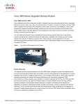
The Cisco CSR 1000V Series Cloud Services Router provides a cloud-based router that is deployed on
a virtual machine (VM) instance on x86 server hardware. The Cisco CSR 1000V provides selected
Cisco IOS XE features on a virtualization platform.
When the Cisco CSR 1000V virtual IOS XE software is deployed on a VM, the Cisco IOS XE software
functions just as if it were deployed on a traditional Cisco hardware platform. The Cisco CSR 1000V
includes a virtual Route Processor and a virtual Forwarding Processor (FP) as part of its architecture.
The Cisco CSR 1000V supports a subset of Cisco IOS XE software features and technologies. For more
information, see the “Supported Cisco IOS XE Technologies” section on page 1-13.
The Cisco CSR 1000V provides secure connectivity from the enterprise premise (such as a branch office
or data center) to the public or private cloud.
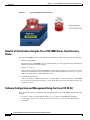
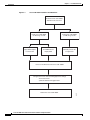
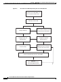
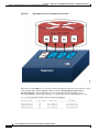
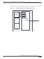
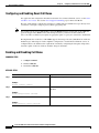
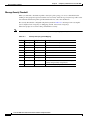
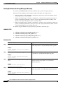
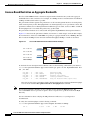
Figure 1-1 shows the basic virtual form factor for the Cisco CSR 1000V. The Cisco CSR 1000V is
deployed as a virtual machine on a hypervisor. Optionally, you can use a virtual switch (vSwitch),
depending on your deployment. You can use selected Cisco equipment for some components. The
supported components will depend on your software release.
Cisco CSR 1000V Series Cloud Services Router Software Configuration Guide
OL-27477-07
1-1
Chapter 1
Cisco CSR 1000V Series Cloud Services Router Overview
Introduction
Figure 1-1
Cisco CSR 1000V Virtual Form Factor
Benefits of Virtualization Using the Cisco CSR 1000V Series Cloud Services
Router
The Cisco CSR 1000V Series uses the benefits of virtualization in the cloud to provide the following:
•
Hardware independence
Because the Cisco CSR 1000V runs on a virtual machine, it can be supported on any x86 hardware
that the virtualization platform supports.
•
Sharing of resources
The resources used by the Cisco CSR 1000V are managed by the hypervisor, and resources can be
shared among VMs. The amount of hardware resources that the VM server allocates to a specific
VM can be reallocated to another VM on the server.
•
Flexibility in deployment
You can easily move a VM from one server to another. Thus, you can move the Cisco CSR 1000V
from a server in one physical location to a server in another physical location without moving any
hardware resources.
Software Configuration and Management Using the Cisco IOS XE CLI
You can perform software configuration and management of the Cisco CSR 1000V using the following
methods:
•
Provision a serial port in the VM and connect to access the Cisco IOS XE CLI commands.
•
Use the VM console or the console on the virtual serial port to access the Cisco IOS XE CLI
commands.
Cisco CSR 1000V Series Cloud Services Router Software Configuration Guide
1-2
OL-27477-07
Chapter 1
Cisco CSR 1000V Series Cloud Services Router Overview
Virtual Machine Requirements
A serial port can be used to manage a Cisco CSR 1000V VM only if the underlying hypervisor
supports associating a serial port with a VM. For example, the Citrix XenServer environment
does not support serial port association. See your hypervisor documentation for details.
Note
•
Use remote SSH/Telnet to access the Cisco IOS XE CLI commands.
The Cisco CSR 1000V also supports management and configuration using the following products:
•
Cisco CSR 1000V REST API
•
Cisco Prime Network Services Controller
For more information, see the “Management Support” section on page 1-20.
Router Interfaces
The Cisco CSR 1000V router interfaces perform the same functionality as those on hardware-based
Cisco routers. The Cisco CSR 1000V interfaces function as follows:
•
Interfaces are logically named as the Gigabit Ethernet (GE) interfaces.
•
The available interface numbering depends on the Cisco CSR 1000V version.
(Cisco IOS XE Release 3.11S and later) The interface numbering is as follows:
– Interface port numbering is from 1 and up to the number of interfaces supported.
– GigabitEthernet interface 0 is no longer supported beginning with this release.
– You can designate any interface as the management interface. You can change the management
interface when deploying the OVA template on first-time installation.
(Cisco IOS XE Release 3.10S and earlier) The interface numbering is as follows:
– Interface port numbering is from 0 and up to the number of interfaces supported.
– Gigabit Ethernet interface 0 is reserved for the management interface used for obtaining the
licenses and upgrading software.
•
Caution
At first boot, the Cisco CSR 1000V router interfaces are mapped to the vNIC interfaces on the VM
based on the vNIC enumeration to the Cisco CSR 1000V; on subsequent boot, the Cisco CSR 1000V
router interfaces are mapped to the vNIC MAC address
If upgrading to Cisco IOS XE Release 3.11S from an earlier release, Cisco recommends you update your
configuration to remove the GigabitEthernet 0 management interface before upgrading. Because the
GigabitEthernet 0 interface is no longer supported beginning with Cisco IOS XE Release 3.11S, you will
receive system errors if the upgraded configuration includes this interface.
For more information, see the “Mapping Cisco CSR 1000V Network Interfaces to VM Network
Interfaces” section on page 10-1.
Virtual Machine Requirements
The Cisco CSR 1000V runs only on a virtual machine. This section describes the virtual machine
requirements for the router.
Cisco CSR 1000V Series Cloud Services Router Software Configuration Guide
OL-27477-07
1-3
Chapter 1
Cisco CSR 1000V Series Cloud Services Router Overview
Virtual Machine Requirements
•
Virtual Machines
•
Hypervisor Support
•
Server Requirements
Virtual Machines
A virtual machine (VM) is a software implementation of a computing environment in which an operating
system (OS) or program can be installed and run. The VM typically emulates a physical computing
environment, but requests for CPU, memory, hard disk, network and other hardware resources are
managed by a virtualization layer which translates these requests to the underlying physical hardware.
You can deploy an Open Virtualization Archive (OVA) file. The OVA file package simplifies the process
of deploying a VM by providing a complete definition of the parameters and resource allocation
requirements for the new VM.
An OVA file consists of a descriptor (.ovf) file, a storage (.vmdk) file and a manifest (.mf) file.
•
ovf file—Descriptor file which is an xml file with extension .ovf which consists of all the metadata
about the package. It encodes all the product details, virtual hardware requirements and licensing.
•
vmdk file—File format that encodes a single virtual disk from a VM.
•
mf file—Optional file that stores the SHA key generated during packaging.
You can also install the Cisco CSR 1000V using an .iso file and manually create the VM in the
hypervisor.
For more information, see the “Cisco CSR 1000V Series Cloud Services Router Overview” section on
page 1-1.
Hypervisor Support
A hypervisor enables multiple operating systems to share a single hardware host machine. While each
operating system appears to have the dedicated use of the host's processor, memory, and other resources;
the hypervisor controls and allocates only needed resources to each operating system and ensures that
the operating systems (VMs) do not disrupt each other.
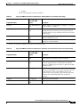
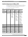
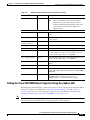
The Cisco CSR 1000V is supported for installation on selected hypervisors. The following table lists the
supported hypervisor versions for your software release.
Note
Beginning with Cisco IOS XE Release 3.11S, the Cisco CSR 1000V can also be deployed on Cisco
Amazon Web Services. For more information, see the Cisco CSR 1000V Series Cloud Services Router
Deployment Guide for Amazon Web Services.
Cisco CSR 1000V Series Cloud Services Router Software Configuration Guide
1-4
OL-27477-07
Chapter 1
Cisco CSR 1000V Series Cloud Services Router Overview
Virtual Machine Requirements
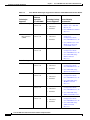
Table 1-1
Support Matrix for Hypervisor Versions
Cisco CSR 1000V
IOS XE Release
VMware
ESXi
Citrix
XenServer
Kernel Based Virtual
Machine (KVM)
Microsoft Hyper-V
3.9S
5.0
Not supported
Not supported
Not supported
3.10S
5.0
5.1
6.0.2
3.11S
3.12S
5.0
5.1
5.0
5.1
5.5
6.02
6.1
•
Linux KVM based on Not supported
Red Hat Enterprise
Linux 6.31
•
Red Hat Enterprise
Virtualization 3.1
•
Linux KVM based on Not supported
Red Hat Enterprise
Linux 6.31
•
Red Hat Enterprise
Virtualization 3.1
•
Ubuntu 12.04.03 LTS
Server 64 Bits2
•
Ubuntu 12.04.03 LTS Windows Server
2012 R2
Server 64 Bits2
•
KVM installation on
OpenStack using
.qcow2 file
1. Requires Kernel version 2.6.3.2 and QEMU 0.12.
2. Requires QEMU-x86_64 version 1.0 (qemu-kvm-1.0), Copyright (c) 2003-2008 Fabrice Bellard.
Hypervisor features may differ depending on the hypervisor, and not all features in a given hypervisor
version may be supported. The hypervisor versions listed are those officially tested and supported by the
Cisco CSR 1000V. See the following sections for more information:
•
VMware ESXi Support Information, page 4-1
•
Citrix XenServer Support Information, page 5-1
•
Kernel Virtual Machine Support Information, page 6-1
•
Microsoft Hyper-V Support Information, page 7-1
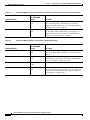
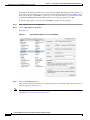
Hypervisor vNIC Requirements
Depending on the Cisco CSR 1000V release version, each of the hypervisors supports different virtual
network interface card (vNIC) types. The Cisco CSR 1000V also supports a different maximum number
of vNICs depending on the hypervisor. Some versions and hypervisors also support the ability to add
and remove vNICs without powering down the VM. This feature is known as vNIC Hot Add/Remove.
The following table lists the supported vNICs and the minimum and maximum number of vNICs
supported for each VM instance.
Cisco CSR 1000V Series Cloud Services Router Software Configuration Guide
OL-27477-07
1-5
Chapter 1
Cisco CSR 1000V Series Cloud Services Router Overview
Virtual Machine Requirements
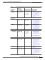
Table 1-2
Cisco CSR 1000V vNIC Support
Cisco IOS XE Release:
3.9S
3.10S, 3.11S
3.12S
NIC Types Supported
VMXNET3
VMXNET3
VMXNET3
Max. number of vNICs
per VM instance
10
10
10
vNIC Hot Add/Remove
Support
No
Yes
Yes
Single Root I/O
virtualization (SR-IOV)
Support
—
—
No
NIC Types Supported
—
VIF
VIF
Max. number of vNICs
per VM instance
—
7
7
vNIC Hot Add/Remove
Support
—
No
No
Single Root I/O
virtualization (SR-IOV)
Support1
—
—
Yes2
NIC Types Supported
—
Virtio
Virtio
Max. number of vNICs
per VM instance
—
10
26
vNIC Hot Add/Remove
Support
—
Yes3
Yes3
Single Root I/O
virtualization (SR-IOV)
Support1
—
—
Yes2
NIC Types Supported
—
—
HV NETVSC
Max. number of vNICs
per VM instance
—
—
3
vNIC Hot Add/Remove
Support
—
—
No
Single Root I/O
virtualization (SR-IOV)
Support
—
—
No
VMware ESXi:
Citrix XenServer:
KVM:
Microsoft Hyper-V:
1. Requires the host hardware to support the Intel VT-d or AMD IOMMU specification.
SR-IOV is not supported with Virtual LANs (VLANs).
2. Supported beginning with the Cisco IOS XE 3.12.1 release.
3. Requires the Cisco CSR 1000V to be reloaded.
Cisco CSR 1000V Series Cloud Services Router Software Configuration Guide
1-6
OL-27477-07
Chapter 1
Cisco CSR 1000V Series Cloud Services Router Overview
Virtual Machine Requirements
The VMXNET3, VIF and Virtio NIC types are para-virtualized NICs.
Note
vNIC Hot Remove requires reloading the Cisco CSR 1000V.
Cisco CSR 1000V and Hypervisor Limitations
This section describes performance limitations due to how the Cisco CSR 1000V integrates with the
supported hypervisors.
Cisco CSR 1000V and Hypervisor Limitations for Cisco IOS XE Release 3.12S
•
When the Cisco CSR 1000V is installed on Microsoft Hyper-V, the interface numbers can change
after Microsoft Hyper-V fails over to a new server, or restarts after a live migration.
– If the server is set to perform ungraceful failover, there is no workaround.
– If the server is set to perform graceful failover or restart, enter the clear platform software
vnic-if nvtable command before executing the failover or restart.
This issue is not seen if the maximum number of interfaces is configured.
•
When the Cisco CSR 1000V is installed on Microsoft Hyper-V, if you want to configure a VLAN,
you must configure the VLAN interfaces on Microsoft Hyper-V using the Hyper-V Power Shell CLI.
•
When the Cisco CSR 1000V is installed on Microsoft Hyper-V and an NSF-based virtual hard disk
is used, if there is a network connectivity issue between the Cisco CSR 1000V and the NSF server,
the Cisco CSR 1000V is unable to use the virtual hard disk even if the network connection is
restored. You must reboot the Cisco CSR 1000V to restore access to the virtual hard disk.
Cisco CSR 1000V and Hypervisor Limitations for Cisco IOS XE Release 3.10S
•
Configuring Network Based Application Recognition (NBAR), or Application Visibility and
Control (AVC) support on the Cisco CSR 1000V requires a minimum of 4GB of DRAM on the VM,
even when using the one vCPU configuration on the VM.
•
On the Cisco CSR 1000V, all the NICs are logically named as the Gigabit Ethernet interface. The
Cisco CSR 1000V does support the 10G IXGBE vNIC in passthrough mode; but that interface also
is also logically named as a Gigabit Ethernet interface. Note that with emulated devices like
VMXNET3/PV/VIRTIO from the hypervisor, the Cisco CSR 1000V is not aware of the underlying
interfaces. The vSwitch may be connected to a 10-GB physical NIC or 1-GB physical NICs or
multiple NICs (with NIC teaming on the hypervisor) as well.
•
The Cisco CSR 1000V supports an MTU range from 1500 to 9216 bytes. However, the maximum
MTU supported on your hypervisor version may be lower. The MTU value configured on the
Cisco CSR 1000V should not exceed the maximum MTU value supported on the hypervisor.
Cisco CSR 1000V and Hypervisor Limitations for Cisco IOS XE Release 3.9S
The following are the Cisco CSR 1000V and VMware ESXi limitations for Cisco IOS XE Release 3.9S:
•
The Cisco CSR 1000V interface bandwidth defaults to 1 GB, irrespective of the hypervisor’s
physical NIC bandwidth. The routing protocols (OSPF, EIGRP) use the Cisco CSR 1000V interface
bandwidth values for calculating the costs, not the physical NIC bandwidth.
Cisco CSR 1000V Series Cloud Services Router Software Configuration Guide
OL-27477-07
1-7
Chapter 1
Cisco CSR 1000V Series Cloud Services Router Overview
Cisco CSR 1000V Series Software License Overview
•
When a Cisco CSR 1000V interface is directly connected to a physical router, and that physical
router’s connecting interface goes down, the change is not reflected on the Cisco CSR 1000V. This
is because the Cisco CSR 1000V is actually connected to the hypervisor’s vSwitch and the vSwitch
uplink port is connected to the physical interface of the router. This behavior is expected.
•
The Cisco CSR 1000V provides an MTU range from 1500 to 9216 bytes. However, ESXi 5.0
supports only a maximum value of 9000 bytes.
Server Requirements
The server and processor requirements are different depending on the Cisco CSR 1000V release.
Table 1-3
Server Requirements
Cisco CSR 1000V Release Intel
AMD
Cisco IOS XE Release
3.9S
Intel Nehalem and
later-generation
processors are
supported.
Not supported
Cisco IOS XE Releases
3.10S, 3.11S, 3.12S
Intel processors prior
to the Nehalem
generation are
supported.
Supported
For more information, see the Cisco CSR 1000V Series Cloud Services Router Release Notes.
Note
In Cisco IOS XE Release 3.9S and earlier, the Cisco CSR 1000V uses instructions not supported on Intel
pre-Nehalem generation processors. The existence of the required Nehalem or later processor instruction
set is determined at boot time. If the required instructions are not present, the following message is
displayed:
%IOSXEBOOT-4-BOOT_HALT: (rp/0): Halted boot due to missing CPU feature
requirement(s)
For more information, see the “Installation Overview” section on page 3-1.
Cisco CSR 1000V Series Software License Overview
The Cisco CSR 1000V Series software supports the standard Cisco software licensing process in
Cisco IOS XE. The software activation process is similar to other Cisco router products, but there are
some differences and additional requirements.
The Cisco CSR 1000V supports the following license types depending on the software release:
•
Perpetual and subscription term licenses for 1, 3, and 5 years based on the following attributes:
– Cisco IOS XE technology packages (Standard, Advanced and Premium)
– Maximum supported throughput level (10, 25, 50, 100, 250, or 500 Mbps, and 1, 2.5 or 5 Gbps )
Cisco CSR 1000V Series Cloud Services Router Software Configuration Guide
1-8
OL-27477-07
Chapter 1
Cisco CSR 1000V Series Cloud Services Router Overview
Cisco CSR 1000V Series Software License Overview
•
Memory upgrade licenses (selected technology packages and throughput levels only)
•
60-day evaluation licenses
The following table lists the available license types for your release. See the Cisco CSR 1000V Series
Cloud Services Router Release Notes for the specific license SKUs and the Cisco CSR 1000V Router
Data Sheet.
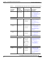
Table 1-4
Cisco CSR 1000V Software License Types
Cisco CSR 1000V Version
License Type
License Term
All
Evaluation
60 days
Cisco IOS XE Release 3.9S Base subscription technology package
1, 3, and 5 years
licenses (Standard, Advanced, and Premium)
for the following throughput maximums:
Cisco IOS XE Releases
3.10S, 3.11S
•
10 Mbps
•
25 Mbps
•
50 Mbps
Base subscription Standard technology
package licenses for the following throughput
maximums:
•
10 Mbps
•
50 Mbps
•
100 Mbps
•
250 Mbps
•
500 Mbps
•
1 Gbps
•
1 and 3 years
•
Perpetual
Base subscription Advanced and Premium
technology package licenses for the following
throughput maximums:
•
10 Mbps
•
50 Mbps
•
100 Mbps
•
250 Mbps
•
(Cisco IOS XE Release 3.11S and later)
License to add 8 GB of memory with
route reflector support1
Note
Selected licenses are available
through a Cisco service representative
only.
Cisco CSR 1000V Series Cloud Services Router Software Configuration Guide
OL-27477-07
1-9
Chapter 1
Cisco CSR 1000V Series Cloud Services Router Overview
Cisco CSR 1000V Series Software License Overview
Table 1-4
Cisco CSR 1000V Software License Types (continued)
Cisco CSR 1000V Version
License Type
Cisco IOS XE Release
3.12S
All of the licenses supported in Cisco IOS XE
Release 3.11S, plus the following licenses:
License Term
•
1 and 3 years
•
Perpetual
•
1 and 3 years
•
Perpetual
Base subscription Advanced and Premium
technology package licenses for the following
throughput maximum:
•
1 Gbps
Base subscription Standard, Advanced and
Premium technology package licenses for the
following throughput maximum:
•
2.5 Gbps
Base subscription Standard technology
package licenses for the following throughput
maximum:
•
Cisco IOS XE Release
3.12.1S
5 Gbps
New technology package licenses are
supported:
•
IPBase package license, with the same
feature set as the Standard package
•
Security package license, with the same
feature set as the Advanced package
•
AX package license, with the same
feature set as the Premium package
Cisco recommends using these technology
packages for compatibility with future
releases. All technology packages support the
same throughput maximums as feature sets in
earlier releases.
1. Available for the Premium package only. The additional memory is allocated to IOSD processes on the router only. The
memory upgrade license does not add available memory on the VM.
The supported performance indicates the maximum throughput supported by the Cisco CSR 1000V for
the license. If the throughput exceeds the supported performance, the router may experience dropped
packets and you will receive notification that the supported performance has been exceeded. The
Cisco CSR 1000V uses a performance limiter to regulate the throughput level. For more information, see
the “License-Based Restriction on Aggregate Bandwidth” section on page 13-6.
If additional performance is required, an additional license for a separate Cisco CSR 1000V VM must
be purchased. The Cisco CSR 1000V supports only one router instance per VM.
The Cisco CSR 1000V software licenses operate as follows:
•
Each software license can be used for only one VM.
•
You can install more than one license on a VM, but the multiple licenses can only apply to that VM.
Cisco CSR 1000V Series Cloud Services Router Software Configuration Guide
1-10
OL-27477-07
Chapter 1
Cisco CSR 1000V Series Cloud Services Router Overview
Cisco CSR 1000V Series Software License Overview
•
Similar to other Cisco hardware products, the software license is node-locked to the unique device
identifier (UDI) of that product. The Cisco CSR 1000V generates a Virtual UDI (vUDI) when first
installed on the VM, and licenses are node-locked to that vUDI. One license per VM instance is
required. Instances that are cloned from a repository must generate a new vUDI.
Note
When you clone the Cisco CSR 1000V, you will automatically get a new vUDI, and all the
licenses from the original VM should be removed.
•
You must purchase and install a new technology level license if you want to upgrade or downgrade
the technology level. For example, if you have a Premium technology package license and you want
to downgrade to the Standard technology package, you must purchase a new Standard technology
package license.
•
In Cisco IOS XE Release 3.10S, the default license will not enable advanced IPsec features and
MPLS.
•
The Cisco CSR 1000V does not provide or support Right-to-Use performance licenses.
•
You will receive warning notices that the subscription term license will expire beginning eight
weeks before license expiration.
The licenses must be activated in order for the Cisco CSR 1000V network ports to provide the supported
throughput.
When the Cisco CSR 1000V is first booted, the router operates in evaluation mode, and provides limited
feature support and is limited to a maximum throughput of 2.5 Mbps. To obtain the full feature support
and throughput provided by your license, you must do the following:
•
To access the features supported in your license, you must enter the license boot-level command
and set it to the level supported by your license (Standard, Advanced, or Premium).
•
To set the throughput level to match your license, you must enter the platform
hardware-throughput command.
•
You must then reboot the Cisco CSR 1000V for these settings to take effect.
If the throughput license expires or becomes invalid, the maximum throughput of the router reverts to
2.5 Mbps. When the 60-day evaluation license expires, the maximum throughput reverts to 2.5 Mbps and
to the limited feature set.
The subscription term begins on the day the license is issued.
For more information about license activation, see the “Managing Cisco CSR 1000V Licenses” section
on page 13-1.
If you rehost the Cisco CSR 1000V to a VM on another server, the following rules apply:
•
You must purchase a new rehost software license that lasts for the period remaining on the original
license.
•
If the original license was renewed, the rehosted software license will last for the period remaining
on the renewed license.
•
You have a 60-day grace period to remove the software license from the original server hardware
and activate it on the rehosted server hardware.
The Cisco CSR 1000V also supports Cisco License Manager and Cisco License Call Home. For more
information about the standard Cisco IOS XE software activation procedure, and information about
Cisco License Manager and Cisco License Call Home, see the Software Activation Configuration Guide,
Cisco IOS XE Release 3S.
Cisco CSR 1000V Series Cloud Services Router Software Configuration Guide
OL-27477-07
1-11
Chapter 1
Cisco CSR 1000V Series Cloud Services Router Overview
Cisco CSR 1000V Series Architecture Differences from Hardware Platforms
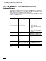
Cisco CSR 1000V Series Architecture Differences from
Hardware Platforms
Unlike traditional Cisco hardware router platforms, the Cisco CSR 1000V Series is a virtual router that
runs independently on an x86 machine. As a result, the Cisco CSR 1000V Series architecture has unique
attributes that differentiate it from hardware-based router platforms.
For example, Table 1-5 lists a comparison of some key areas where the Cisco CSR 1000V Series differs
from the Cisco ASR 1000 series routers.
Table 1-5
Cisco CSR 1000V Series Architecture Differences with Cisco ASR 1000 Series Routers
Feature
Cisco ASR 1000 Series
Cisco CSR 1000V Series
Hard Disk
Supported.
The Cisco CSR 1000V does not include
a hard disk. The software image is
stored on bootflash only (8 GB).
Physical resources
Managed by architecture of the
hardware platform.
Managed by the hypervisor. Physical
resources are shared among VMs.
Console types supported
Physical serial port.
•
VMware soft console
•
Network option (virtual terminal
server)
•
Named pipe option
•
Physical serial port on the ESXi or
KVM host
ROMMON
Supported.
The Cisco CSR 1000V does not include
ROMMON, but uses GRUB to provide
similar but more limited functionality.
Break Signal
Supported.
Not supported.
Port numbering
See the Cisco ASR1000
documentation.
Gigabit Ethernet x ports only.
ISSU
Supports In-Service Software
Upgrades (ISSU).
Not supported.
Subpackage upgrades
Supports installation of
subpackages for specific SPAs
and SIP SPAs.
Subpackages not supported. The
Cisco CSR 1000V does not support
SPAs.
Diagnostic mode
Supported.
Not supported.
Dynamic addition/deletion Supported.
of ports
Supported.1
1. Requires reload of the VM.
Cisco CSR 1000V Series Cloud Services Router Software Configuration Guide
1-12
OL-27477-07
Chapter 1
Cisco CSR 1000V Series Cloud Services Router Overview
Supported Cisco IOS XE Technologies
Supported Cisco IOS XE Technologies
The Cisco CSR 1000V Series Cloud Services Router supports selected Cisco IOS XE technologies. The
Cisco CSR 1000V supports a more limited set of functionality compared to other router platforms.
Table 1-6 lists the major Cisco IOS XE technologies the Cisco CSR 1000V supports. Technologies not
listed are not currently supported on the Cisco CSR 1000V. Not all features in a given technology may
be supported. To verify support for specific features, use Cisco Feature Navigator. For more information,
see the “Using Cisco Feature Navigator” section on page 1-22.
In Cisco IOS XE Release 3.9S, the Cisco CSR 1000V supports a maximum of 150 IPsec tunnels.
Beginning with Cisco IOS XE Release 3.10S, the number of IPSec tunnels depends on the installed
license. For more information, see the Cisco CSR 1000V Series Cloud Services Router Release Notes.
The information listed in this table applies only if using the Cisco IOS XE CLI. Support for Cisco IOS
XE technologies is more limited in the following scenarios:
•
When deploying the Cisco CSR 1000V on Amazon Web Services (AWS)
For more information, see the Cisco CSR 1000V Series Cloud Services Router Deployment Guide
for Amazon Web Services.
•
When using the REST API to manage the Cisco CSR 1000V
For more information, see the “Configuring Support for Management Using the REST API” section
on page 14-1. For information about Cisco IOS XE technologies supported by the REST API, see
the Cisco CSR 1000V Series Cloud Services Router REST API Management Reference Guide.
•
When using Cisco Prime Network Services Controller (PNSC) to remotely manage the
Cisco CSR 1000V
For more information on features supported, see the “Configuring Support for Remote Management
by the Cisco Prime Network Services Controller” section on page 15-1.
Note
The license technology packages available beginning with Cisco IOS XE release 3.12.1 support the same
sets of features as technology packages supported in previous releases. For example, the IPBase package
supports Standard package features, the Security package supports Advanced package features, and the
AX package supports the Premium package set of features.
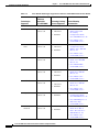
Table 1-6
Cisco IOS XE Technologies Supported on the Cisco CSR 1000V Cloud Services Router
Technologies
Supported
Minimum Cisco IOS
XE Release
Required for
Technology Package
Cisco CSR 1000V
Licenses Supported
See the Following
Documentation:
IP:
•
IPv4 Routing
•
IPv4
Fragmentation
and Reassembly
•
IPv6 Forwarding
Cisco IOS XE
Release 3.9S
•
Standard
•
Advanced
•
Premium
•
IP Addressing
Configuration Guide
Library, Cisco IOS XE
Release 3S
•
Cisco IOS IP Addressing
Services Command
Reference
Cisco CSR 1000V Series Cloud Services Router Software Configuration Guide
OL-27477-07
1-13
Chapter 1
Cisco CSR 1000V Series Cloud Services Router Overview
Supported Cisco IOS XE Technologies
Table 1-6
Cisco IOS XE Technologies Supported on the Cisco CSR 1000V Cloud Services Router
Technologies
Supported
•
•
•
IPv6 Routing
Minimum Cisco IOS
XE Release
Required for
Technology Package
Cisco CSR 1000V
Licenses Supported
Cisco IOS XE
Release 3.9S
Generic Routing Cisco IOS XE
Encapsulation
Release 3.9S
(GRE)
LISP
Cisco IOS XE
Release 3.9S
•
Standard
•
Advanced
•
Premium
•
Standard
•
Advanced
•
Premium
•
Premium
See the Following
Documentation:
•
IPv6 Configuration Guide
Library, Cisco IOS XE
Release 3S
•
Cisco IOS IPv6 Command
Reference
•
Interface and Hardware
Component
Configuration Guide,
Cisco IOS XE Release 3S
•
Cisco IOS Interface and
Hardware Component
Command Reference
•
IP Routing: LISP
Configuration Guide,
Cisco IOS XE Release 3S
•
Cisco IOS IP Routing:
LISP Command
Reference
•
IP Routing: BGP
Configuration Guide,
Cisco IOS XE Release 3S
•
Cisco IOS IP Routing:
BGP Command Reference
•
IP Routing: EIGRP
Configuration Guide,
Cisco IOS XE Release 3S
•
Cisco IOS IP Routing:
EIGRP Command
Reference
•
IP Routing: ISIS
Configuration Guide,
Cisco IOS XE Release 3S
•
Cisco IOS IP Routing:
ISIS Command Reference
•
IP Routing: OSPF
Configuration Guide,
Cisco IOS XE Release 3S
•
Cisco IOS IP Routing:
OSPF Command
Reference
Basic Routing:
•
•
•
•
BGP
EIGRP
ISIS
OSPF
Cisco IOS XE
Release 3.9S
Cisco IOS XE
Release 3.9S
Cisco IOS XE
Release 3.9S
Cisco IOS XE
Release 3.9S
•
Standard
•
Advanced
•
Premium
•
Standard
•
Advanced
•
Premium
•
Standard
•
Advanced
•
Premium
•
Standard
•
Advanced
•
Premium
Cisco CSR 1000V Series Cloud Services Router Software Configuration Guide
1-14
OL-27477-07
Chapter 1
Cisco CSR 1000V Series Cloud Services Router Overview
Supported Cisco IOS XE Technologies
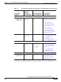
Table 1-6
Cisco IOS XE Technologies Supported on the Cisco CSR 1000V Cloud Services Router
Technologies
Supported
•
Performance
Routing
Minimum Cisco IOS
XE Release
Required for
Technology Package
Cisco CSR 1000V
Licenses Supported
Cisco IOS XE
Release 3.9S
•
Standard
•
Advanced
•
Premium
•
Advanced
•
Premium
See the Following
Documentation:
•
Performance Routing
Configuration Guide,
Cisco IOS XE Release 3S
•
Cisco IOS Performance
Routing Command
Reference
•
IP Multicast: IGMP
Configuration Guide,
Cisco IOS XE Release 3S
•
Cisco IOS IP Multicast
Command Reference
•
IP Multicast: PIM
Configuration Guide,
Cisco IOS XE Release 3S
•
Cisco IOS IP Multicast
Command Reference
•
IP Switching Cisco
Express Forwarding
Configuration Guide,
Cisco IOS XE Release 3S
•
Cisco IOS IP Switching
Command Reference
•
Wide-Area Networking
Configuration Guide:
Overlay Transport
Virtualization, Cisco IOS
XE Release 3S
•
Cisco IOS Wide-Area
Networking Command
Reference
IP Multicast:
•
•
IGMP
PIM
Cisco IOS XE
Release 3.9S
Cisco IOS XE
Release 3.9S
•
Advanced
•
Premium
IP Switching:
•
Cisco Express
Forwarding
Cisco IOS XE
Release 3.9S
•
Standard
•
Advanced
•
Premium
Wide Area Networking:
•
OTV
Cisco IOS XE
Release 3.10S
•
Premium
•
VxLAN
Cisco IOS XE
Release 3.11S
•
Premium
•
CSR 1000V VxLAN
Support
•
WCCPv2
Cisco IOS XE
Release 3.9S
•
Premium
•
IP Application Services
Configuration Guide,
Cisco IOS XE Release 3S
•
Cisco IOS IP Application
Services Command
Reference
Cisco CSR 1000V Series Cloud Services Router Software Configuration Guide
OL-27477-07
1-15
Chapter 1
Cisco CSR 1000V Series Cloud Services Router Overview
Supported Cisco IOS XE Technologies
Table 1-6
Technologies
Supported
Cisco IOS XE Technologies Supported on the Cisco CSR 1000V Cloud Services Router
Minimum Cisco IOS
XE Release
Required for
Technology Package
Cisco CSR 1000V
Licenses Supported
See the Following
Documentation:
VPN:
•
•
•
•
•
•
IPsec VPN
DMVPN
Easy VPN
FlexVPN
GETVPN
SSL VPN
Cisco IOS XE
Release 3.9S
•
Advanced
•
Premium
Cisco IOS XE
Release 3.9S
•
Advanced
•
Premium
Cisco IOS XE
Release 3.9S
•
Advanced
•
Premium
Cisco IOS XE
Release 3.9S
•
Advanced
•
Premium
Cisco IOS XE
Release 3.11S
•
Advanced
•
Premium
Cisco IOS XE
3.12.1S
•
Advanced
•
Premium
•
Secure Connectivity
Configuration Guide
Library, Cisco IOS XE
Release 3S
•
Cisco IOS Security
Command Reference
•
SSL VPN Configuration
Guide, Cisco IOS Release
15M&T
•
Cisco IOS Security
Command Reference
•
Multiprotocol Label
Switching Configuration
Guide Library, Cisco IOS
XE Release 3S
•
Cisco IOS Multiprotocol
Label Switching
Command Reference
•
Multiprotocol Label
Switching Configuration
Guide Library, Cisco IOS
XE Release 3S
•
Cisco IOS Multiprotocol
Label Switching
Command Reference
•
MPLS: Layer 3 VPNs
Configuration Guide,
Cisco IOS XE Release 3S
•
Cisco IOS Multiprotocol
Label Switching
Command Reference
MPLS:
•
•
•
MPLS
EoMPLS
VRF
Cisco IOS XE
Release 3.9S
Cisco IOS XE
Release 3.9S
Cisco IOS XE
Release 3.9S
•
•
Premium
Premium
•
Standard
•
Advanced
•
Premium
Cisco CSR 1000V Series Cloud Services Router Software Configuration Guide
1-16
OL-27477-07
Chapter 1
Cisco CSR 1000V Series Cloud Services Router Overview
Supported Cisco IOS XE Technologies
Table 1-6
Cisco IOS XE Technologies Supported on the Cisco CSR 1000V Cloud Services Router
Technologies
Supported
•
VPLS
Minimum Cisco IOS
XE Release
Required for
Technology Package
Cisco CSR 1000V
Licenses Supported
Cisco IOS XE
Release 3.10S
•
Premium
See the Following
Documentation:
•
MPLS Layer 2 VPNs
Configuration Guide,
Cisco IOS XE Release 3S
•
Cisco IOS Multiprotocol
Label Switching
Command Reference
•
SNMP Configuration
Guide, Cisco IOS XE
Release 3S
•
Cisco IOS Network
Management Command
Reference
•
Flexible NetFlow
Configuration Guide,
Cisco IOS XE Release 3S
•
Cisco IOS Network
Management Command
Reference
•
Secure Shell
Configuration Guide,
Cisco IOS XE Release 3S
•
Cisco IOS Security
Command Reference
•
Quality of Service
Solutions Configuration
Guide Library, Cisco IOS
XE Release 3S
•
Cisco IOS Quality of
Service Solutions
Command Reference
•
IP Addressing: NAT
Configuration Guide,
Cisco IOS XE Release 3S
•
Cisco IOS IP Addressing
Services Command
Reference
Network Management:
•
•
•
SNMP
Flexible
NetFlow
Secure Shell
(SSH)
Cisco IOS XE
Release 3.9S
Cisco IOS XE
Release 3.9S
Cisco IOS XE
Release 3.9S
•
Standard
•
Advanced
•
Premium
•
Standard
•
Advanced
•
Premium
•
Standard
•
Advanced
•
Premium
QoS:
•
QoS
Cisco IOS XE
Release 3.9S
Cisco IOS XE
Release 3.9S:
•
Premium
Cisco IOS XE
Release 3.10S and
later:
•
Advanced
•
Premium
•
Standard
•
Advanced
•
Premium
Services:
•
NAT
Cisco IOS XE
Release 3.9S
Cisco CSR 1000V Series Cloud Services Router Software Configuration Guide
OL-27477-07
1-17
Chapter 1
Cisco CSR 1000V Series Cloud Services Router Overview
Supported Cisco IOS XE Technologies
Table 1-6
Cisco IOS XE Technologies Supported on the Cisco CSR 1000V Cloud Services Router
Technologies
Supported
Minimum Cisco IOS
XE Release
Required for
Technology Package
Cisco CSR 1000V
Licenses Supported
See the Following
Documentation:
Access Control:
•
•
•
•
•
•
•
AAA
Access Control
Lists
IP SLA
RADIUS
TACACS+
Layer3 Firewall
Zone-Based
Firewall
Cisco IOS XE
Release 3.9S
Cisco IOS XE
Release 3.9S
Cisco IOS XE
Release 3.9S
Cisco IOS XE
Release 3.9S
Cisco IOS XE
Release 3.9S
Cisco IOS XE
Release 3.9S
Cisco IOS XE
Release 3.9S
•
Standard
•
Advanced
•
Premium
•
Standard
•
Advanced
•
Premium
•
Premium
•
Standard
•
Advanced
•
Premium
•
Standard
•
Advanced
•
Premium
•
Advanced
•
Premium
•
Advanced
•
Premium
•
Authentication
Authorization and
Accounting
Configuration Guide,
Cisco IOS XE Release 3S
•
Cisco IOS Security
Command Reference
•
Securing the Data Plane
Configuration Guide
Library, Cisco IOS XE
Release 3S
•
Cisco IOS Security
Command Reference
•
IP SLAs Configuration
Guide, Cisco IOS XE
Release 3S
•
Cisco IOS IP SLAs
Command Reference
•
RADIUS Configuration
Guide Cisco IOS XE
Release 3S
•
Cisco IOS Security
Command Reference
•
TACACS+ Configuration
Guide Cisco IOS XE
Release 3S
•
Cisco IOS Security
Command Reference
•
MPLS: Layer 3 VPNs
Configuration Guide,
Cisco IOS XE Release 3S
•
Cisco IOS Multiprotocol
Label Switching
Command Reference
•
Security Configuration
Guide: Zone-Based
Policy Firewall, Cisco
IOS XE Release 3S
•
Cisco IOS Security
Command Reference
Cisco CSR 1000V Series Cloud Services Router Software Configuration Guide
1-18
OL-27477-07
Chapter 1
Cisco CSR 1000V Series Cloud Services Router Overview
Supported Cisco IOS XE Technologies
Table 1-6
Cisco IOS XE Technologies Supported on the Cisco CSR 1000V Cloud Services Router
Technologies
Supported
Minimum Cisco IOS
XE Release
Required for
Technology Package
Cisco CSR 1000V
Licenses Supported
See the Following
Documentation:
Application Services:
•
•
Application
Visibility and
Control (AVC)
NBAR
Cisco IOS XE
Release 3.9S
Cisco IOS XE
Release 3.9S
•
•
Premium
Premium
•
Cisco AVC Solution
Guide for IOS XE Release
3.9
•
Cisco Application
Visibility and Control
User Guide for IOS XE
Release 3.10S
•
Cisco Application
Visibility and Control
User Guide for IOS
Release 15.4(1)T and IOS
XE Release 3.11S
•
NBAR Protocol Library,
Cisco IOS XE Release 3S
•
QoS: NBAR
Configuration Guide,
Cisco IOS XE Release 3S1
•
First Hop Redundancy
Protocols Configuration
Guide, Cisco IOS XE
Release 3S
•
Cisco IOS First Hop
Redundancy Protocols
Command Reference
•
Configuration Guide for
AppNav-XE for Cisco
Cloud Services Router
1000V Series
Redundancy:
•
HSRP
Cisco IOS XE
Release 3.9S
•
Standard
•
Advanced
•
Premium
WAAS:
•
Integrated
AppNav-XE
Cisco IOS XE
Release 3.9S
•
Premium
1. Download the NBAR2 protocol pack for your release on the Cisco CSR 1000V software download page. For more
information, see the “NBAR Protocol Pack” section of the QoS: NBAR Protocol Library, Cisco IOS XE Release 3S.
Cisco CSR 1000V Series Cloud Services Router Software Configuration Guide
OL-27477-07
1-19
Chapter 1
Cisco CSR 1000V Series Cloud Services Router Overview
Management Support
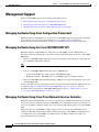
Management Support
The Cisco CSR 1000V supports the following management options:
•
Managing the Router Using Cisco Configuration Professional
•
Managing the Router Using the Cisco CSR 1000V REST API
•
Managing the Router Using Cisco Prime Network Services Controller
Managing the Router Using Cisco Configuration Professional
Beginning with Cisco IOS XE Release 3.12S, the Cisco CSR 1000V supports managing the router using
Cisco Configuration Professional. The minimum version required is Cisco Configuration
Professional 2.8. For more information, see the Cisco Configuration Professional documentation.
Managing the Router Using the Cisco CSR 1000V REST API
Beginning with Cisco IOS XE Release 3.10S, the Cisco CSR 1000V provides a REST API as an
alternative method of managing the router. The following requirements apply to the Cisco CSR 1000V
REST API:
•
Note
•
The Cisco CSR 1000V REST API supports only selected features and technologies compared to the
Cisco IOS XE command-line interface.
The Cisco CSR 1000V currently does not support IPv6 for the REST API.
The Cisco CSR 1000V REST API is supported over HTTPS only.
– In Cisco IOS XE Release 3.10S, you must enable HTTPS support.
– Beginning with Cisco IOS XE Release 3.11S, HTTPS support is enabled by default.
•
The Cisco CSR 1000V Amazon Machine Image (AMI) does not support management of the router
using the REST API.
For more information about configuring the router to support management using the REST API, see the
“Configuring Support for Management Using the REST API” section on page 14-1. For more
information about using the Cisco CSR 1000V REST API, see the Cisco CSR 1000V Series Cloud
Services Router REST API Management Reference Guide.
Managing the Router Using Cisco Prime Network Services Controller
Beginning with Cisco IOS XE Release 3.11S, you can use the Cisco Prime Network Services Controller
to provision, manage, and monitor the Cisco CSR 1000V. Cisco Prime Network Services Controller can
be used to streamline configuration when you are provisioning and managing many Cisco CSR 1000V
VMs.
If deploying the Cisco CSR 1000V on ESXi, support for remote management using PNSC can be
configured while deploying the OVA template. If deploying the Cisco CSR 1000V on other hypervisors,
or if launching the Cisco CSR 1000V on an AWS instance, the PNSC configuration settings are
performed using the Cisco IOS CLI.
Cisco CSR 1000V Series Cloud Services Router Software Configuration Guide
1-20
OL-27477-07
Chapter 1
Cisco CSR 1000V Series Cloud Services Router Overview
Management Support
For more information about configuring the Cisco CSR 1000V to enable remote management using
Cisco Prime Network Services Controller, see the “Configuring Support for Remote Management by the
Cisco Prime Network Services Controller” section on page 15-1. For more information about
configuring Cisco Prime Network Services Controller and using the GUI for remote management, see
the following documentation:
•
Cisco Prime Network Services Controller Quick Start Guide
•
Cisco Prime Network Services Controller User Guide
•
Cisco Prime Network Services Controller CLI Configuration Guide
Table 1-7 lists the Cisco Prime Network Services Controller versions compatible with the
Cisco CSR 1000V.
Table 1-7
Cisco CSR 1000V Compatibility with Cisco Prime Network Services Controller
Cisco IOS XE Release
for Cisco CSR 1000V
Cisco IOS XE Release
3.11S
Cisco IOS XE Release
3.12S
Cisco Prime Network
Services Controller
Version
Version 3.2
Version 3.2
Version 3.2.2
Hypervisors
Supported for
Implementation
•
VMware ESXi
•
KVM
Features Supported
•
Hostname, DNS, User
Credentials
•
Interfaces:
cloud-facing, externalfacing
•
Interface types: Gigabit
Ethernet, loopback
•
NAT, NTP
•
ACL, Firewall
•
Routing: BGP, OSPF,
static routes
•
Syslog
•
VMware ESXi
•
Sub-interface
•
KVM
•
IPSec VPN
•
DHCP Server/Relay
•
Routing: EIGRP
•
SNMP
•
NAT: Overload, PAT
Related Cisco Product Compatibility
•
Cisco Unified Computing System (UCS) Products
Cisco Unified Computing System (UCS) Products
Table 1-8 lists Cisco CSR 1000V compatibility with Cisco Unified Computing System (UCS) products.
Cisco CSR 1000V Series Cloud Services Router Software Configuration Guide
OL-27477-07
1-21
Chapter 1
Cisco CSR 1000V Series Cloud Services Router Overview
Finding Support Information for Platforms and Cisco Software Images
Table 1-8
Cisco CSR 1000V Compatibility with Cisco UCS Servers
Cisco IOS XE Release 3.9S/3.10S/3.11S/3.12S:
Cisco Unified
Computing System
(UCS) Products
The Cisco UCS server requirements are:
•
VMware-certified
•
4 or more cores configured
•
6 GB or more memory
•
VMware vCenter or standalone VMware vSphere client
installed to manage the ESXi server
See the Cisco UCS interoperability documentation to determine
the UCS hardware and software that is compatible with the
supported hypervisors.
See also the Cisco CSR 1000V Series Cloud Services Router
Release Notes for specific CPU requirements.
Finding Support Information for Platforms and Cisco Software
Images
Cisco software is packaged in feature sets consisting of software images that support specific platforms.
The feature sets available for a specific platform depend on which Cisco software images are included
in a release. To identify the set of software images available in a specific release or to find out if a feature
is available in a given Cisco IOS XE software image, you can use Cisco Feature Navigator, the Software
Advisor, or the software release notes.
Using Cisco Feature Navigator
Use Cisco Feature Navigator to find information about platform support and software image support.
Cisco Feature Navigator enables you to determine which Cisco IOS XE software images support a
specific software release, feature set, or platform. To access Cisco Feature Navigator, go to
http://www.cisco.com/go/cfn. An account on Cisco.com is not required.
Using the Software Advisor
To see if a feature is supported by a Cisco IOS XE release, to locate the software document for that
feature, or to check the minimum Cisco IOS XE software requirements with your router, Cisco maintains
the Software Advisor tool on Cisco.com at:
http://tools.cisco.com/Support/Fusion/FusionHome.do
You must be a registered user on Cisco.com to access this tool.
Cisco CSR 1000V Series Cloud Services Router Software Configuration Guide
1-22
OL-27477-07
Chapter 1
Cisco CSR 1000V Series Cloud Services Router Overview
Finding Support Information for Platforms and Cisco Software Images
Using the Software Release Notes
Cisco IOS XE software release notes provide the following information:
•
Platform support
•
Memory recommendations
•
New features
•
Open and resolved severity 1 and 2 caveats
Release notes are intended to be release-specific for the most current release, and the information
provided in these documents may not be cumulative in providing information about features that first
appeared in previous releases. See Cisco Feature Navigator for cumulative feature information.
For more information, see the Cisco CSR 1000V Series Cloud Services Router Release Notes.
Cisco CSR 1000V Series Cloud Services Router Software Configuration Guide
OL-27477-07
1-23
Chapter 1
Cisco CSR 1000V Series Cloud Services Router Overview
Finding Support Information for Platforms and Cisco Software Images
Cisco CSR 1000V Series Cloud Services Router Software Configuration Guide
1-24
OL-27477-07
CH A P T E R
2
Using Cisco IOS XE Software
This chapter provides information about the Cisco IOS XE software used to configure the
Cisco CSR 1000V Series Cloud Services Router. The Cisco CSR 1000V Series uses standard
Cisco IOS XE CLI commands and conventions.
Using Keyboard Shortcuts
Commands are not case sensitive. You can abbreviate commands and parameters if the abbreviations
contain enough letters to be different from any other currently available commands or parameters.
Table 2-1 lists the keyboard shortcuts for entering and editing commands.
Table 2-1
Keyboard Shortcuts
Keystrokes
Purpose
Ctrl-B or
the Left Arrow key
Move the cursor back one character.
Ctrl-F or
the Right Arrow key
Move the cursor forward one character.
Ctrl-A
Move the cursor to the beginning of the command line.
Ctrl-E
Move the cursor to the end of the command line.
Esc B
Move the cursor back one word.
Esc F
Move the cursor forward one word.
Using the History Buffer to Recall Commands
The history buffer stores the last 10 commands you entered. History substitution allows you to access
these commands without retyping them, by using special abbreviated commands.
Table 2-2 lists the history substitution commands.
Cisco CSR 1000V Series Cloud Services Router Software Configuration Guide
OL-27477-07
2-1
Chapter 2
Using Cisco IOS XE Software
Understanding the Command Modes
Table 2-2
History Substitution Commands
Command
Purpose
Ctrl-P or the Up Arrow key
Recall commands in the history buffer, beginning with the most
recent command. Repeat the key sequence to recall successively
older commands.
Ctrl-N or the Down Arrow key
Return to more recent commands in the history buffer after
recalling commands with Ctrl-P or the Up Arrow key.
Router# show history
While in EXEC mode, list the last several commands you have just
entered.
Understanding the Command Modes
The command modes available in the traditional Cisco IOS CLI are exactly the same as the command
modes available in Cisco IOS XE.
Use the CLI to access Cisco IOS XE software. Because the CLI is divided into many different modes,
the commands available to you at any given time depend on the mode that you are currently in. Entering
a question mark (?) at the CLI prompt allows you to obtain a list of commands available for each
command mode.
When you log in to the CLI, you are in user EXEC mode. User EXEC mode contains only a limited
subset of commands. To have access to all commands, you must enter privileged EXEC mode, normally
by using a password. From privileged EXEC mode, you can issue any EXEC command—user or
privileged mode—or you can enter global configuration mode. Most EXEC commands are one-time
commands. For example, show commands show important status information, and clear commands
clear counters or interfaces. The EXEC commands are not saved when the software reboots.
Configuration modes allow you to make changes to the running configuration. If you later save the
running configuration to the startup configuration, these changed commands are stored when the
software is rebooted. To enter specific configuration modes, you must start at global configuration mode.
From global configuration mode, you can enter interface configuration mode and a variety of other
modes, such as protocol-specific modes.
Table 2-3 describes how to access and exit various common command modes of the Cisco IOS XE
software. It also shows examples of the prompts displayed for each mode.
Table 2-3
Accessing and Exiting Command Modes
Command
Mode
Access Method
Prompt
Exit Method
User EXEC
Log in.
Router>
Use the logout command.
Privileged
EXEC
From user EXEC mode, use the enable EXEC Router#
command.
To return to user EXEC mode, use
the disable command.
Cisco CSR 1000V Series Cloud Services Router Software Configuration Guide
2-2
OL-27477-07
Chapter 2
Using Cisco IOS XE Software
Getting Help
Table 2-3
Accessing and Exiting Command Modes (continued)
Command
Mode
Access Method
Prompt
Exit Method
Global
configuration
From privileged EXEC mode, use the
configure terminal privileged EXEC
command.
Router(config)#
To return to privileged EXEC
mode from global configuration
mode, use the exit or end
command.
Interface
configuration
From global configuration mode, specify an
interface using an interface command.
Router(config-if)#
To return to global configuration
mode, use the exit command.
To return to privileged EXEC
mode, use the end command.
Getting Help
Entering a question mark (?) at the CLI prompt displays a list of commands available for each command
mode. You can also get a list of keywords and arguments associated with any command by using the
context-sensitive help feature.
To get help specific to a command mode, a command, a keyword, or an argument, use one of the
commands listed in Table 2-4:
Table 2-4
Help Commands and Purpose
Command
Purpose
help
Provides a brief description of the help system in any
command mode.
abbreviated-command-entry?
Provides a list of commands that begin with a particular
character string. (No space between command and question
mark.)
abbreviated-command-entry<Tab> Completes a partial command name.
?
Lists all commands available for a particular command mode.
command ?
Lists the keywords or arguments that you must enter next on
the command line. (Space between command and question
mark.)
Finding Command Options
This section provides an example of how to display syntax for a command. The syntax can consist of
optional or required keywords and arguments. To display keywords and arguments for a command, enter
a question mark (?) at the configuration prompt or after entering part of a command followed by a space.
The Cisco IOS XE software displays a list and brief description of available keywords and arguments.
For example, if you were in global configuration mode and wanted to see all the keywords or arguments
for the arap command, you would type arap ?.
The <cr> symbol in command help output stands for “carriage return.” On older keyboards, the carriage
return key is the Return key. On most modern keyboards, the carriage return key is the Enter key. The
<cr> symbol at the end of command help output indicates that you have the option to press Enter to
Cisco CSR 1000V Series Cloud Services Router Software Configuration Guide
OL-27477-07
2-3
Chapter 2
Using Cisco IOS XE Software
Getting Help
complete the command and that the arguments and keywords in the list preceding the <cr> symbol are
optional. The <cr> symbol by itself indicates that no more arguments or keywords are available and that
you must press Enter to complete the command.
Table 2-5 shows examples of how you can use the question mark (?) to assist you in entering commands.
Table 2-5
Finding Command Options
Command
Comment
Router> enable
Password: <password>
Router#
Enter the enable command and
password to access privileged EXEC
commands. You are in privileged
EXEC mode when the prompt changes
to a “#” from the “>”; for example,
Router> to Router#.
Router# configure terminal
Enter configuration commands, one per line. End with CNTL/Z.
Router(config)#
Enter the configure terminal
privileged EXEC command to enter
global configuration mode. You are in
global configuration mode when the
prompt changes to Router(config)#.
Router(config)# interface GigabitEthernet ?
<0-6>
GigabitEthernet interface number
Enter interface configuration mode by
specifying the serial Gigabit Ethernet
interface that you want to configure
using the interface GigabitEthernet
number global configuration command.
Router(config)# interface GigabitEthernet 1
Router(config-if)#
Enter ? to display what you must enter
next on the command line.
When the <cr> symbol is displayed,
you can press Enter to complete the
command.
You are in interface configuration mode
when the prompt changes to
Router(config-if)#.
Note
The Cisco CSR 1000V supports
only Gigabit Ethernet
interfaces.
Cisco CSR 1000V Series Cloud Services Router Software Configuration Guide
2-4
OL-27477-07
Chapter 2
Using Cisco IOS XE Software
Getting Help
Table 2-5
Finding Command Options (continued)
Command
Comment
Router(config-if)# ?
Interface configuration commands:
.
.
.
ip
Interface Internet Protocol config commands
keepalive
Enable keepalive
lan-name
LAN Name command
llc2
LLC2 Interface Subcommands
load-interval
Specify interval for load calculation for an
interface
locaddr-priority
Assign a priority group
logging
Configure logging for interface
loopback
Configure internal loopback on an interface
mac-address
Manually set interface MAC address
mls
mls router sub/interface commands
mpoa
MPOA interface configuration commands
mtu
Set the interface Maximum Transmission Unit (MTU)
netbios
Use a defined NETBIOS access list or enable
name-caching
no
Negate a command or set its defaults
nrzi-encoding
Enable use of NRZI encoding
ntp
Configure NTP
.
.
.
Router(config-if)#
Enter ? to display a list of all the
interface configuration commands
available for the Gigabit Ethernet
interface. This example shows only
some of the available interface
configuration commands.
Router(config-if)# ip ?
Interface IP configuration subcommands:
access-group
Specify access control for packets
accounting
Enable IP accounting on this interface
address
Set the IP address of an interface
authentication
authentication subcommands
bandwidth-percent
Set EIGRP bandwidth limit
bgp
BGP interface commands
broadcast-address
Set the broadcast address of an interface
cef
Cisco Express Forwarding interface commands
cgmp
Enable/disable CGMP
dhcp
Configure DHCP parameters for this interface
.
.
.
Router(config-if)# ip
Router(config-if)# ip address ?
A.B.C.D
IP address
dhcp
IP Address negotiated via DHCP
pool
IP Address autoconfigured from a local DHCP pool
Router(config-if)# ip address
Enter the command that you want to
configure for the interface. This
example uses the ip command.
Enter ? to display what you must enter
next on the command line. This
example shows only some of the
available interface IP configuration
commands.
Enter the command that you want to
configure for the interface. This
example uses the ip address command.
Enter ? to display what you must enter
next on the command line. In this
example, you must enter an IP address
or the negotiated keyword.
A carriage return (<cr>) is not
displayed; therefore, you must enter
additional keywords or arguments to
complete the command.
Cisco CSR 1000V Series Cloud Services Router Software Configuration Guide
OL-27477-07
2-5
Chapter 2
Using Cisco IOS XE Software
Using the no and default Forms of Commands
Table 2-5
Finding Command Options (continued)
Command
Comment
Router(config-if)# ip address 172.16.0.1 ?
A.B.C.D
IP subnet mask
Router(config-if)# ip address 172.16.0.1
Enter the keyword or argument that you
want to use. This example uses the
172.16.0.1 IP address.
Enter ? to display what you must enter
next on the command line. In this
example, you must enter an IP subnet
mask.
A <cr> is not displayed; therefore, you
must enter additional keywords or
arguments to complete the command.
Router(config-if)# ip address 172.16.0.1 255.255.255.0 ?
secondary
Make this IP address a secondary address
<cr>
Router(config-if)# ip address 172.16.0.1 255.255.255.0
Enter the IP subnet mask. This example
uses the 255.255.255.0 IP subnet mask.
Enter ? to display what you must enter
next on the command line. In this
example, you can enter the secondary
keyword, or you can press Enter.
A <cr> is displayed; you can press
Enter to complete the command, or
you can enter another keyword.
Router(config-if)# ip address 172.16.0.1 255.255.255.0
Router(config-if)#
In this example, Enter is pressed to
complete the command.
Using the no and default Forms of Commands
Almost every configuration command has a no form. In general, use the no form to disable a function.
Use the command without the no keyword to re-enable a disabled function or to enable a function that
is disabled by default. For example, IP routing is enabled by default. To disable IP routing, use the no
ip routing command; to re-enable IP routing, use the ip routing command. The Cisco IOS XE software
command reference publications provide the complete syntax for the configuration commands and
describe what the no form of a command does.
Many CLI commands also have a default form. By issuing the command default command-name, you
can configure the command to its default setting. The Cisco IOS XE software command reference
publications describe the function of the default form of the command when the default form performs
a different function than the plain and no forms of the command. To see what default commands are
available on your system, enter default ? in the appropriate command mode.
Saving Configuration Changes
Use the copy running-config startup-config command to save your configuration changes to the startup
configuration so that the changes will not be lost if the software reloads or a power outage occurs. For
example:
Router# copy running-config startup-config
Building configuration...
Cisco CSR 1000V Series Cloud Services Router Software Configuration Guide
2-6
OL-27477-07
Chapter 2
Using Cisco IOS XE Software
Managing Configuration Files
It might take a minute or two to save the configuration. After the configuration has been saved, the
following output appears:
[OK]
Router#
This task saves the configuration to NVRAM.
Managing Configuration Files
On the Cisco CSR 1000V, the startup configuration file is stored in the NVRAM partition. As a matter
of routine maintenance on any Cisco router, users should backup the startup configuration file by
copying the startup configuration file from NVRAM onto one of the router’s other file systems and,
additionally, onto a network server. Backing up the startup configuration file provides an easy method
of recovering the startup configuration file in the event the startup configuration file in NVRAM
becomes unusable for any reason.
The copy command can be used to backup startup configuration files. The following examples show the
startup configuration file in NVRAM being backed up:
Example 1: Copying a Startup Configuration File to Bootflash
Router# dir bootflash:
Directory of bootflash:/
11
drwx
16384
Jan 24 2012 04:53:55 -05:00
lost+found
12
-rw289243620 Jan 24 2012 04:54:55 -05:00
308257 drwx
4096
Jan 24 2012 04:57:06 -05:00
core
876097 drwx
4096
Jan 24 2012 04:57:07 -05:00
.prst_sync
63277 drwx
4096
Jan 24 2012 04:57:10 -05:00 .rollback_timer
13
-rw0
Jan 24 2012 04:57:19 -05:00
tracelogs.
csr1000v-adventerprisek9.2012-01-23_12.39.SSA.bin
Router# copy nvram:startup-config bootflash:
Destination filename [startup-config]?
3517 bytes copied in 0.647 secs (5436 bytes/sec)
Directory of bootflash:/
11
drwx
16384
Jan 24 2012 04:53:55 -05:00
lost+found
12
-rw289243620 Jan 24 2012 04:54:55 -05:00
308257 drwx
4096
Jan 24 2012 04:57:06 -05:00
core
876097 drwx
4096
Jan 24 2012 04:57:07 -05:00
.prst_sync
632737 drwx
4096
Jan 24 2012 04:57:10 -05:00 .rollback_timer
13
-rw0
Jan 24 2012 04:57:19 -05:00
tracelogs.
csr1000v-adventerprisek9.2012-01-23_12.39.SSA.bin
14 -rw7516
Jul 2 2012 15:01:39 -07:00
startup-config
Example 2: Copying a Startup Configuration File to a TFTP Server
Router# copy bootflash:startup-config tftp:
Address or name of remote host []? 172.17.16.81
Destination filename [pe24_asr-1002-confg]? /auto/tftp-users/user/startup-config
!!
3517 bytes copied in 0.122 secs (28828 bytes/sec)
For more detailed information on managing configuration files, see the “Managing Configuration Files”
section in the Configuration Fundamentals Configuration Guide, Cisco IOS XE Release 3S.
Cisco CSR 1000V Series Cloud Services Router Software Configuration Guide
OL-27477-07
2-7
Chapter 2
Using Cisco IOS XE Software
Filtering the Output of show and more Commands
NVRAM File Security
The Cisco CSR 1000V encrypts some of the disk partitions internal to the VM to provide extra security
around sensitive data that may be stored on the router. For example, information in NVRAM is encrypted
so that it is not visible to administrative entities with access to the physical hard disk that the
Cisco CSR 1000V is stored on.
Filtering the Output of show and more Commands
You can search and filter the output of show and more commands. This functionality is useful if you
need to sort through large amounts of output or if you want to exclude output that you need not see.
To use this functionality, enter a show or more command followed by the “pipe” character ( | ); one of
the keywords begin, include, or exclude; and a regular expression on which you want to search or filter
(the expression is case sensitive):
show command | {append | begin | exclude | include | redirect | section | tee} regular-expression
The output matches certain lines of information in the configuration file.
Powering Off the Cisco CSR 1000V
To power off the Cisco CSR 1000V, you must power off the VM the router is installed on. For
information about powering off the VM, see your VM vendor documentation.
Cisco CSR 1000V Series Cloud Services Router Software Configuration Guide
2-8
OL-27477-07
CH A P T E R
3
Installation Overview
•
Introduction
•
Obtaining the Cisco CSR 1000V Software
•
Where to Go Next
Introduction
Cisco hardware routers are normally shipped with the Cisco IOS XE software pre-installed. Because the
Cisco CSR 1000V Series Cloud Services Router is not hardware-based, you must download the
Cisco IOS XE software from Cisco.com and install it directly onto the virtual machine. However, as part
of the initial installation process, you must first provision the attributes of the VM so that the
Cisco CSR 1000V software can install and boot.
Note
This document does not provide procedures for deploying the Cisco CSR 1000V in an Amazon Web
Services environment. For more information, see the Cisco CSR 1000V Series Cloud Services Router
Deployment Guide for Amazon Web Services.
Figure 3-1 shows the high-level tasks required to install the Cisco CSR 1000V on the VM. The different
installation options are dependent on the hypervisor being used. See the following sections for more
information.
Cisco CSR 1000V Series Cloud Services Router Software Configuration Guide
OL-27477-07
3-1
Chapter 3
Installation Overview
Introduction
Figure 3-1
Cisco CSR 1000V Installation Task Workflow
Download Cisco CSR 1000V
Software from Cisco.com
Install Cisco CSR 1000V
on VM using .ova File
Deploy OVA Template
to Create VM
Use BDEO Tool to
Deploy OVA
Install Cisco CSR 1000V
on VM using .iso File
Manually Create VM
on Hypervisor
Power on the VM to Boot the Cisco CSR 1000V
Configure the license level and throughput level settings:
- license boot level
- platform hardware throughput level
360887
Reboot the Cisco CSR 1000V
Cisco CSR 1000V Series Cloud Services Router Software Configuration Guide
3-2
OL-27477-07
Chapter 3
Installation Overview
Obtaining the Cisco CSR 1000V Software
Obtaining the Cisco CSR 1000V Software
Step 1
Go to the product page for Cisco Routers at
http://www.cisco.com/en/US/partner/products/hw/routers/index.html
Step 2
Navigate to the Cisco CSR 1000V Cloud Services Router product page.
Step 3
Click the “Download Software” link.
Step 4
Select the Cisco IOS XE release package and click Download Now or Add to Cart.
Follow the instructions for downloading the software.
Cisco CSR 1000V Installation Files
The following file types are included in the Cisco CSR 1000V software image package and are used to
install the Cisco CSR 1000V on the supported hypervisors.
•
.ova
Used for deploying the OVA template on the VM (in TAR format)
•
.iso
Used for installing the software image on the VM (requires manually creating the VM)
•
.qcow2
Used for installing the software image in KVM OpenStack environments.
•
.bin
Used for upgrading and downgrading the software only. For more information, see the “Upgrading
the Cisco IOS XE Software” section on page 9-1.
Note
The .bin upgrade file cannot be used to upgrade AMIs obtained from Amazon Web Services. You
must create a new AMI instance and migrate your configuration and license(s).
Cisco CSR 1000V Installation Options
The Cisco CSR 1000V supports the following installation options:
•
Deploy the OVA template on the VM.
Uses the .ova file. This template creates a VM using recommended preset values. See the
“Deploying the Cisco CSR 1000V OVA Template to the VM” section on page 4-10.
The .ova file can be used only for first-time installation. It cannot be used for upgrading the
Cisco IOS XE software version.
•
Deploy the .ova file on the VM using the Cisco Build, Deploy, Execute OVF (BDEO) configurator.
Uses the BDEO application included in your file package. Using the BDEO tool, you can customize
the VM values and easily deploy the custom VM as part of the Cisco CSR 1000V installation
process. See the “Deploying the Cisco CSR 1000V Software Using the Cisco Build, Deploy,
Execute OVF Tool” section on page 4-14.
Cisco CSR 1000V Series Cloud Services Router Software Configuration Guide
OL-27477-07
3-3
Chapter 3
Installation Overview
Obtaining the Cisco CSR 1000V Software
•
Manually configure the VM using the .iso file.
Uses the .iso file. You can install the .iso file on your host and manually create the VM using your
hypervisor software. For example, if you are installing the Cisco CSR 1000V on VMware, you
would install the .iso file on the VMware ESXi host, and manually create the VM using the vSphere
GUI.
See the following sections:
– Manually Creating the Cisco CSR 1000V VM Using the .iso File (VMware ESXi), page 4-23.
– Manually Creating the Cisco CSR 1000V VM Using the .iso File (Citrix XenServer), page 5-3
– Manually Creating the Cisco CSR 1000V VM Using the .iso File (KVM), page 6-3
– Manually Creating the Cisco CSR 1000V VM Using the .iso File (Microsoft Hyper-V), page 7-2
•
Create the Cisco CSR 1000V instance in KVM using OpenStack
Uses the .qcow2 file. The qcow2 (QEMU Copy on Write) image format is used to create the
Cisco CSR 1000V tenant in the KVM OpenStack cloud environment. See the “Creating the Cisco
CSR 1000V KVM Instance on OpenStack Using the .qcow2 File” section on page 6-5.
For information about upgrading the Cisco IOS XE software, see the “Upgrading the Cisco IOS XE
Software” section on page 9-1.
The following table lists the installation options for the supported hypervisors and the minimum
Cisco IOS XE software release required.
Table 3-1
Cisco CSR 1000V Supported Installation Options
Citrix XenServer
KVM
Microsoft
Hyper-V
Deploy OVA Template 3.9S
Using OVA Wizard
Not supported
Not supported
Not supported
Deploy OVA Using
BDEO
3.9S
Not supported
Not supported
Not supported
Manually Configure
VM Using .iso File
3.9S
3.10S
3.10S
3.12S
NA
3.12S
NA
Installation Option
VMware ESXi
Create the KVM
NA
instance on OpenStack
Using .qcow2 File
Guidelines and Limitations
Be aware of the following general guidelines and restrictions before installing the Cisco CSR 1000V in
your network:
•
If the hypervisor does not support vNIC Hot Add/Remove, do not make any changes to the VM
hardware (memory, CPUs, hard drive size, and so on) while the VM is powered on.
•
(Cisco IOS XE Release 3.11S and later) The GigabitEthernet0 interface is no longer available. You
can designate any interface as the management interface.
•
Cisco IOS XE Release 3.10S and earlier) The GigabitEthernet0 interface is the default management
port and cannot be changed.
Cisco CSR 1000V Series Cloud Services Router Software Configuration Guide
3-4
OL-27477-07
Chapter 3
Installation Overview
Where to Go Next
•
Note
The Cisco IOS XE CLI can be accessed either through the virtual console or on a serial port console.
The console can be selected from GRUB mode during the first-time installation, or it can be changed
using the Cisco IOS XE platform console command after the router boots. For more information,
see the “Booting the Cisco CSR 1000V and Accessing the Console” section on page 8-1.
Some hypervisors may not support serial console access. Verify support using your hypervisor
documentation.
ROMMON and the Cisco CSR 1000V
The Cisco CSR 1000V does not include a ROMMON image similar to what is included in many Cisco
hardware-based routers. During the initial bootloader process, the installation script creates a clean
version of the Cisco CSR 1000V software image known as the Golden Image and places it in a
non-accessible partition. This clean version can be used if the software image is not working properly
or is not bootable.
Note that although the Cisco CSR 1000V does not include ROMMON, the platform does include a GNU
GRand Unified Bootloader (GRUB)-based bootloader. The GRUB function on the Cisco CSR 1000V
provides more limited functionality compared to the ROMMON available on other Cisco platforms.
Note that although ROMMON is not present on the Cisco CSR 1000V, some Cisco IOS XE commands
such as show version may show references to ROMMON in the command output.
Note
After the Cisco CSR 1000V completes the first-time installation, you can configure the router to
automatically enter GRUB mode when the router is booted. For more information, see the “Managing
Cisco CSR 1000V Licenses” section on page 13-1.
Where to Go Next
See the following sections for detailed information on installing the Cisco CSR 1000V in different
hypervisor environments:
•
Installing the Cisco CSR 1000V in VMware ESXi Environments
•
Installing the Cisco CSR 1000V in Citrix XenServer Environments
•
Installing the Cisco CSR 1000V in KVM Environments
•
Installing the Cisco CSR 1000V in Microsoft Hyper-V Environments
Cisco CSR 1000V Series Cloud Services Router Software Configuration Guide
OL-27477-07
3-5
Chapter 3
Installation Overview
Where to Go Next
Cisco CSR 1000V Series Cloud Services Router Software Configuration Guide
3-6
OL-27477-07
CH A P T E R
4
Installing the Cisco CSR 1000V in VMware ESXi
Environments
•
VMware ESXi Support Information
•
Installation Requirements for VMware ESXi
•
Deploying the Cisco CSR 1000V OVA Template to the VM
•
Manually Creating the VM and Installing the Cisco CSR 1000V Software Using the .iso File
(VMware ESXi)
VMware ESXi Support Information
The Cisco CSR 1000V runs on the VMware ESXi hypervisor. You can use the same VMware vSphere
hypervisor to run several VMs. Use the VMware vSphere Client GUI to create and manage VMs.
The VMware vSphere Client is an application for creating, configuring, and managing VMs on the
VMware vCenter Server. The Cisco CSR 1000V can boot from a virtual disk located on the data store.
You can perform basic administration tasks such as starting and stopping the Cisco CSR 1000V using
the VMware vSphere Client.
VMware vCenter Server manages the vSphere environment and provides unified management of all the
hosts and VMs in the data center from a single console.
Table 4-1 lists the VMware virtual machine vendor tools supported for the Cisco CSR 1000V.
Cisco CSR 1000V Series Cloud Services Router Software Configuration Guide
OL-27477-07
4-1
Chapter 4
Installing the Cisco CSR 1000V in VMware ESXi Environments
VMware ESXi Support Information
Table 4-1
VMware Virtual Machine Requirements
Cisco CSR 1000V Version
Supported Tools and Requirements
Cisco IOS XE Release 3.9S PC running the following:
•
Supported vSwitch
VMware standard switch
VMware vSphere Client 5.0
VMware distributed switch
Server running the following:1
•
VMware ESXi 5.0
Installation Tool:
•
Cisco IOS XE Release
3.10S and 3.11S
VMware vCenter
PC running the following:
•
VMware vSphere Client 5.0
Server running the following:
•
VMware standard switch
VMware distributed switch
1
VMware ESXi 5.0 or 5.1
Installation Tool:
•
Cisco IOS XE Release
3.12S, and later
VMware vCenter
PC running the following:
•
VMware vSphere Client 5.0, 5.1,
or 5.5
VMware standard switch
VMware distributed switch
Server running the following:1
•
VMware ESXi 5.0, 5.1, or 5.5
Installation Tool:
•
VMware vCenter
1. For more information about server requirements, see the Cisco CSR 1000V Series Cloud Services Router Release Notes.
Table 4-2 lists the virtual machine requirements for the Cisco CSR 1000V.
Cisco CSR 1000V Series Cloud Services Router Software Configuration Guide
4-2
OL-27477-07
Chapter 4
Installing the Cisco CSR 1000V in VMware ESXi Environments
VMware ESXi Support Information
Table 4-2
VMware Requirements for Cisco CSR 1000V
Cisco CSR 1000V Release
Cisco IOS XE Release 3.9S
VM Configuration Requirements
•
VMware ESXi 5.0
•
Single hard disk
Note
Cisco IOS XE Release 3.10S
Multiple hard disk drives on a VM are not supported.
•
8 GB virtual disk
•
4 virtual CPUs
•
4 GB of RAM
•
3 or more virtual network interface cards
•
VMware ESXi 5.0 or 5.1
•
Single hard disk
Note
Multiple hard disk drives on a VM are not supported.
•
8 GB virtual disk
•
The following virtual CPU configurations are supported:
– 1 virtual CPU, requiring 2.5 GB minimum of RAM
– 4 virtual CPUs, requiring 4 GB minimum of RAM
•
3 or more virtual network interface cards
Cisco CSR 1000V Series Cloud Services Router Software Configuration Guide
OL-27477-07
4-3
Chapter 4
Installing the Cisco CSR 1000V in VMware ESXi Environments
VMware ESXi Support Information
Table 4-2
VMware Requirements for Cisco CSR 1000V
Cisco CSR 1000V Release
Cisco IOS XE Release 3.11S
VM Configuration Requirements
•
VMware ESXi 5.0 or 5.1
•
Single hard disk
Note
Multiple hard disk drives on a VM are not supported.
•
8 GB virtual disk
•
The following virtual CPU configurations are supported:
– 1 virtual CPU, requiring 2.5 GB minimum of RAM
– 2 virtual CPUs, requiring 2.5 GB minimum of RAM
– 4 virtual CPUs, requiring 4 GB minimum of RAM
Cisco IOS XE Release 3.12S
•
3 or more virtual network interface cards
•
VMware ESXi 5.0, 5.1, or 5.5
•
Single hard disk
Note
Multiple hard disk drives on a VM are not supported.
•
8 GB virtual disk
•
The following virtual CPU configurations are supported:
– 1 virtual CPU, requiring 2.5 GB minimum of RAM
– 2 virtual CPUs, requiring 2.5 GB minimum of RAM
– 4 virtual CPUs, requiring 4 GB minimum of RAM
– 8 virtual CPUs, requiring 4 GB minimum of RAM
•
3 or more virtual network interface cards
Supported VMware Features and Operations
VMware supports various features and operations that allow you to manage your virtual applications and
perform operations such as cloning, migration, shutdown and resume.
Some of these operations cause the runtime state of the VM to be saved and then restored upon restarting.
If the runtime state includes traffic-related state, then on resumption or replaying the runtime state,
additional errors, statistics, or messages are displayed on the user console. If the saved state is just
configuration driven, you can use these features and operations without a problem.
Table 4-7 lists the VMware features and operations that are supported on the Cisco CSR 1000V. For more
information about VMware features and operations, see the VMware Documentation.
The following VM features and operations are not supported in all versions of the Cisco CSR 1000V, but
can still be used or performed on non-supported versions at the risk of encountering dropped packets,
dropped connections, and other error statistics:
•
Distributed Resource Scheduling (DRS)
•
Fault Tolerance
•
Resume
•
Snapshot
Cisco CSR 1000V Series Cloud Services Router Software Configuration Guide
4-4
OL-27477-07
Chapter 4
Installing the Cisco CSR 1000V in VMware ESXi Environments
VMware ESXi Support Information
•
Suspend
See the following table for more information.
Table 4-3
Supported VMware Features and Operations: General Features (for vCenter Server Only)
Supported Entities
First Supported
Cisco CSR 1000V
Release
Description
Cloning
Cisco IOS XE Release Enables cloning a virtual machine or template, or cloning a
3.9S1
virtual machine to a template.
Migrating
Cisco IOS XE Release The entire state of the virtual machine as well as its
3.9S
configuration file, if necessary, is moved to the new host
even while the data storage remains in the same location on
shared storage.
vMotion
Cisco IOS XE Release Enables moving the VM from one physical server to another
3.9S
while the VM remains active.
Template
Cisco IOS XE Release Uses templates to create new virtual machines by cloning the
3.9S
template as a virtual machine.
1. This release is a Controlled Availability release limited to selected customers only.
Table 4-4
Supported VMware Features and Operations: Operations (for Both vCenter Server and vSphere Client)
Supported Entities
First Supported
Cisco CSR 1000V
Release
Description
Power On
Cisco IOS XE Release Powers on the virtual machine and boots the guest operating
3.9S
system if the guest operating system is installed.
Power Off
Cisco IOS XE Release Stops the virtual machine until it is powered back. The
3.9S
power off option performs a “hard” power off, which is
analogous to pulling the power cable on a physical machine
and always works.
Shut Down
Not supported.
Shut Down, or “soft” power off, leverages VMware Tools to
perform a graceful shutdown of a guest operating system. In
certain situations, such as when VMware Tools is not
installed or the guest operating system is hung, shut down
might not succeed and using the Power off option is
necessary.
Suspend
Not supported
Suspends the virtual machine.
Reset/Restart
Cisco IOS XE Release Stops the virtual machine and restarts (reboots) it.
3.9S
Cisco CSR 1000V Series Cloud Services Router Software Configuration Guide
OL-27477-07
4-5
Chapter 4
Installing the Cisco CSR 1000V in VMware ESXi Environments
VMware ESXi Support Information
Table 4-4
Supported VMware Features and Operations: Operations (for Both vCenter Server and vSphere Client)
Supported Entities
First Supported
Cisco CSR 1000V
Release
Description
OVF Creation
Cisco IOS XE Release An OVF package captures the state of a virtual machine into
3.9S
a self-contained package. The disk files are stored in a
compressed, sparse format. You can create the OVF file by
exporting it to your local computer.
OVA Creation
Cisco IOS XE Release Single file (OVA) to package the OVF template into a single
3.9S
.ova file. This enables distributing the OVF package as a
single file if it needs to be explicitly downloaded from a
website or moved around using a USB key.
Table 4-5
Supported VMware Features and Operations: Networking Features
Supported Entities
First Supported
Cisco CSR 1000V
Release
Description
Custom MAC address
Cisco IOS XE Release From both vCenter Server and vSphere Client. Allows you
3.9S
to set up the MAC address manually for a virtual network
adapter.
Distributed VSwitch
Cisco IOS XE Release From vCenter Server only. A vSphere distributed switch on
3.9S
a vCenter Server data center can handle networking traffic
for all associated hosts on the data center.
Distributed Resources Scheduler
Cisco IOS XE Release Provides automatic load balancing across hosts.
3.10S
NIC Load Balancing
Cisco IOS XE Release From both vCenter Server and vSphere Client. Load
3.9S
balancing and failover policies allow you to determine how
network traffic is distributed between adapters and how to
reroute traffic if an adapter fails.
Cisco CSR 1000V Series Cloud Services Router Software Configuration Guide
4-6
OL-27477-07
Chapter 4
Installing the Cisco CSR 1000V in VMware ESXi Environments
VMware ESXi Support Information
Table 4-5
Supported VMware Features and Operations: Networking Features (continued)
Supported Entities
NIC Teaming
First Supported
Cisco CSR 1000V
Release
Description
Cisco IOS XE Release From both vCenter Server and vSphere Client. Allows you
3.9S
to set up an environment where each virtual switch connects
to two uplink adapters that form a NIC team. The NIC teams
can then either share the load of traffic between physical and
virtual networks among some or all of its members, or
provide passive failover in the event of a hardware failure or
a network outage.
Note
vSwitch
Table 4-6
NIC Teaming can cause a large number of ARP
packets to flood the Cisco CSR 1000V and overload
the CPU. To avoid this situation, reduce the number
of ARP packets and implement NIC Teaming as
Active-Standby rather than Active-Active.
Cisco IOS XE Release From both vCenter Server and vSphere Client. A vSwitch is
3.9S
a virtualized version of a Layer 2 physical switch. A vSwitch
can route traffic internally between virtual machines and link
to external networks. You can use vSwitches to combine the
bandwidth of multiple network adapters and balance
communications traffic among them. You can also configure
a vSwitch to handle a physical NIC failover.
Supported VMware Features and Operations: High Availability
Supported Entities
VM-Level High Availability
First Supported
Cisco CSR 1000V
Release
Description
Cisco IOS XE Release To monitor operating system failures, VM-Level High
3.9S
Availability monitors heartbeat information in the VMware
High Availability cluster. Failures are detected when no
heartbeat is received from a given virtual machine within a
user-specified time interval. VM-Level High Availability is
enabled by creating a resource pool of VMs using VMware
vCenter Server.
Cisco CSR 1000V Series Cloud Services Router Software Configuration Guide
OL-27477-07
4-7
Chapter 4
Installing the Cisco CSR 1000V in VMware ESXi Environments
VMware ESXi Support Information
Table 4-6
Supported VMware Features and Operations: High Availability (continued)
First Supported
Cisco CSR 1000V
Release
Supported Entities
Description
Host-Level High Availability
Cisco IOS XE Release To monitor physical servers, an agent on each server
3.9S
maintains a heartbeat with the other servers in the resource
pool such that a loss of heartbeat automatically initiates the
restart of all affected virtual machines on other servers in the
resource pool. Host-Level High Availability is enabled by
creating a resource pool of servers or hosts, and enabling
high availability in vSphere.
Fault Tolerance
Cisco IOS XE Release Using high availability, fault tolerance is enabled on the
3.10S
ESXi host. When you enable fault tolerance on the VM
running the Cisco CSR 1000V, a secondary VM on another
host in the cluster is created. If the primary host goes down,
then the VM on the secondary host will take over as the
primary VM for the Cisco CSR 1000V.
Note
Table 4-7
The Cisco CSR 1000V does not use or support Cisco IOS-based high availability. High Availability is
supported on the VM host only.
Supported VMware Features and Operations: Storage Options (for Both vCenter Server and vSphere
Client)
Supported Entities
First Supported
Cisco CSR 1000V
Release
Description
Storage Options (for both vCenter Server and vSphere Client)
Local Storage
Cisco IOS XE Release Local storage is in the internal hard disks located inside your
3.9S
ESXi host. Local storage devices do not support sharing
across multiple hosts. A datastore on a local storage device
can be accessed by only one host.
External Storage Target
Cisco IOS XE Release You can deploy the Cisco CSR 1000V on external storage,
3.9S
that is, a Storage Area Network (SAN).
Mount or Pass Through of USB
Storage
Cisco IOS XE Release You can connect USB sticks to the Cisco CSR 1000V and
3.9S
use them as storage devices. In ESXi, you need to add a USB
controller and then assign the disk devices to the
Cisco CSR 1000V.
•
Cisco CSR 1000V supports USB disk hot-plug.
•
You can use only two USB disk hot-plug devices at a
time.
•
USB hub is not supported.
Cisco CSR 1000V Series Cloud Services Router Software Configuration Guide
4-8
OL-27477-07
Chapter 4
Installing the Cisco CSR 1000V in VMware ESXi Environments
Installation Requirements for VMware ESXi
Installation Requirements for VMware ESXi
Before starting your installation of the Cisco CSR 1000V, you must first set up your VMware
environment, including the necessary host and client software. For example, if you are installing the
Cisco CSR 1000V in a VMware ESXi environment, you must first install the vSphere Client.
Table 4-8 lists the installation requirements for VMware ESXi.
Table 4-8
Installation Requirements for VMware ESXi
VMware ESXi
Requirement
Cisco IOS XE
Release 3.9S
VMware ESXi
5.0
version(s) supported
Supported vCPU
configurations1
Virtual CPU cores
required3
1 vCPU: requires
minimum 4 GB
RAM allocation
1
Cisco IOS XE
Release 3.10S
Cisco IOS XE
Release 3.11S
Cisco IOS XE
Release 3.12S
5.0, 5.1
5.0, 5.1
5.0, 5.1, 5.5
•
1 vCPU:
requires
minimum
2.5 GB RAM
allocation2
•
1 vCPU:
requires
minimum
2.5 GB RAM
allocation2
•
1 vCPU:
requires
minimum
2.5 GB RAM
allocation2
•
4 vCPUs:
requires
minimum
4 GB RAM
allocation
•
2 vCPUs:
requires
minimum
2.5 GB RAM
allocation
•
2 vCPUs:
requires
minimum
2.5 GB RAM
allocation
•
4 vCPUs:
requires
minimum
4 GB RAM
allocation
•
4 vCPUs:
requires
minimum
4 GB RAM
allocation
•
8 vCPUs:
requires
minimum
4 GB RAM
allocation
1
1
1
Virtual hard disk size 8 GB minimum
8 GB minimum
8 GB minimum
8 GB minimum
Supported vNICs
VMXNET3
VMXNET3
VMXNET3
Minimum number of 3
vNICs required4
3
3
3
Maximum number of 10
vNICs supported
10
10
10
Default video, SCSI
controller set
Required
Required
Required
Required
Virtual CD/DVD
drive installed
Required
Required
Required
Required
VMXNET3
Cisco CSR 1000V Series Cloud Services Router Software Configuration Guide
OL-27477-07
4-9
Chapter 4
Installing the Cisco CSR 1000V in VMware ESXi Environments
Deploying the Cisco CSR 1000V OVA Template to the VM
1. The required vCPU configuration depends on the throughput license and technology package installed. For more information, see
the data sheet for your release.
2. Not automatically supported when deploying the OVA. If configuring Cisco Network Based Application Recognition (NBAR), or
Cisco Application Visibility and Control (AVC), a 4-GB RAM allocation is required.
3. Requires a 64-bit processor with Virtualization Technology (VT) enabled in the BIOS setup of the host machine.
4. When deploying the OVA, three vNICs are automatically created. You can manually add vNICs to the VM after the Cisco CSR
1000V has booted.
Deploying the Cisco CSR 1000V OVA Template to the VM
You can use the provided CSR 1000V OVA file package to easily deploy the Cisco CSR 1000V to the
VM. The OVA package includes an .ovf file that contains a default VM configuration based on the
Cisco IOS XE release and the supported hypervisor. See the “Guidelines and Limitations” section of the
installation configuration that is included in the OVA file.
Note
•
Deploying the OVA Template to the VM
•
Deploying the Cisco CSR 1000V Software Using the Cisco Build, Deploy, Execute OVF Tool
•
Editing the Cisco CSR 1000V Basic Properties Using the vSphere GUI
•
Adding Custom Properties for the Cisco CSR 1000V
The Citrix XenServer, KVM and Microsoft Hyper-V implementations do not support deploying the VM
using the .ova file. You must manually install the VM using the .iso file.
Deploying the OVA Template to the VM
The following restrictions apply to deploying the OVA template to the VM:
•
(Cisco IOS XE Releases 3.10S and 3.11S) The OVA package only creates a VM with 4 virtual CPUs.
To change to the 1 or 2 virtual CPU configuration, you must first deploy the OVA template, and then
use vSphere to change the virtual CPU configuration and the required RAM allocation.
If the virtual CPU configuration is changed, the Cisco CSR 1000V must be rebooted. Changing the
RAM allocation does not require rebooting the Cisco CSR 1000V. Beginning with Cisco IOS XE
3.12S, the OVA package provides an option to select the virtual CPU configuration.
Note
When deploying the OVA package, the VM requires two virtual CD/DVD drives, one for the
OVF environment file and one for the .iso file.
Cisco CSR 1000V Series Cloud Services Router Software Configuration Guide
4-10
OL-27477-07
Chapter 4
Installing the Cisco CSR 1000V in VMware ESXi Environments
Deploying the Cisco CSR 1000V OVA Template to the VM
Perform the following steps in VMware vSphere Client:
Step 1
Log in to the VMware vSphere Client.
Step 2
From the vSphere Client Menu Bar, choose File > Deploy OVF Template.
Step 3
In the OVA Wizard, point the source to the Cisco CSR 1000V OVA to be deployed. Click Next.
The OVF Template Details displays, showing information about the OVA file. Click Next.
Step 4
Under Name and Inventory Location, specify the name for the VM and click Next.
Step 5
(Cisco IOS XE Release 3.12S and later): Under Deployment Configuration, select the desired hardware
configuration profile from the drop-down menu and click Next.
Step 6
Under Storage, select the Datastore to use for the VM. Click Next.
Step 7
Under Disk Format, select the disk format option:
•
Thick Provision Lazy Zeroed
•
Thick Provision Eager Zeroed
Note
The Thin Provision option is not supported. The Thick Provision Eager Zeroed option takes
longer to install but provides better performance.
Click Next.
Step 8
Under Network Mapping, allocate one or more virtual network interface card (vNIC) on the destination
network using the drop-down list. The options for mapping the vNICs differ depending on the release
version:
•
(Cisco IOS XE Release 3.11S and later): Select the network mappings for the 3 default vNICs
created during the OVA deployment. You can choose which vNIC will map to the router’s
management interface when setting the bootstrap properties (see Table 4-10).
•
(Cisco IOS XE Release 3.10S and earlier) The vNIC allocated in this step is mapped to the
GigabitEthernet0 management interface on the router.
Select the vNIC to connect at Power On. Click Next.
When the Cisco CSR 1000V installation using the OVA template is complete, two additional vNICS are
allocated. The Cisco CSR 1000V supports up to ten vNICs; additional vNICs must be manually created
on the VM.
The Properties screen displays.
Step 9
Configure the properties for the VM.
The available properties differ depending on the Cisco IOS XE release that you are using. See Table 4-9
for Cisco IOS XE Release 3.9S and 3.10S and Table 4-10 for Cisco IOS XE Release 3.11S and later.
Note
The bootstrap properties are optional when creating the VM. You can set these properties to easily
provision the VM before starting it up.
Cisco CSR 1000V Series Cloud Services Router Software Configuration Guide
OL-27477-07
4-11
Chapter 4
Installing the Cisco CSR 1000V in VMware ESXi Environments
Deploying the Cisco CSR 1000V OVA Template to the VM
Table 4-9
OVA Bootstrap Properties for Cisco IOS XE Release 3.9S and 3.10S
Property
Description
Bootstrap Properties
Login Username
Sets the login username for the router.
Login Password
Sets the login password for the router.
Management IPv4
Address/Mask
Sets the management gateway address/mask in IPv4 format
for the GigabitEthernet0 management interface.
Management IPv4
Default Gateway
Sets the default management gateway IP address in IPv4
format for the GigabitEthernet0 management interface.
Router name
Configures the hostname of the router.
Features
Enable HTTP Server
(Cisco IOS XE Release 3.9S only) Enables an HTTP server
for system configuration and administration via a web
browser.
Enable HTTPS Server (Cisco IOS XE Release 3.10S only) Enables an HTTPS
server for system configuration and administration via a web
browser. Required if using the REST API to perform system
configuration.
Note
Enable SSH Login
The HTTPS server is enabled by default beginning in
Cisco IOS XE Release 3.11S. This field was
removed.
Enables remote login using SSH and disables remote login
via Telnet. Requires that the login username and password
are set.
Additional Configuration Properties
Enable Password
Configures the password for privileged (enable) access.
Domain Name
Configures the network domain name.
Table 4-10
OVA Bootstrap Properties for Cisco IOS XE Release 3.11S and Later
Property
Description
Bootstrap Properties
Login Username
Sets the login username for the router.
Login Password
Sets the login password for the router.
Management
Interface
Designates the management interface for the
Cisco CSR 1000V. The format must be GigabitEthernetx or
GigabitEthernetx.xxx.
Note
The GigabitEthernet0 interface is no longer
supported beginning in Cisco IOS XE Release 3.11S.
Cisco CSR 1000V Series Cloud Services Router Software Configuration Guide
4-12
OL-27477-07
Chapter 4
Installing the Cisco CSR 1000V in VMware ESXi Environments
Deploying the Cisco CSR 1000V OVA Template to the VM
Table 4-10
OVA Bootstrap Properties for Cisco IOS XE Release 3.11S and Later (continued)
Property
Description
Management vLAN
Configures the dot1Q VLAN interface. Requires the
management interface to be configured using the
GigabitEthernetx.xxx format.
Management
Interface IPv4
Address/Mask
Configures the IPv4 address and subnet mask for the
management interface.
Management IPv4
Default Gateway
(Cisco IOS XE
Release 3.11S)
Configures the IPv4 management default gateway address. If
using DHCP, enter “dhcp” in the field.
Management IPv4
Gateway (Cisco IOS
XE Release 3.12S)
Configures the IPv4 management default gateway address. If
using DHCP, enter “dhcp” in the field.
Management IPv4
Network (Cisco IOS
XE Release 3.12S)
Configures the IPv4 Network (such as “192.168.2.0/24” or
“192.168.2.0 255.255.255.0”) that the management gateway
should route to. If a default route (0.0.0.0/0) is desired, this
may be left blank.
Remote Management
IPv4 Address
(Optional) Configures the IP address used for remote
management of the Cisco CSR 1000V by the REST API or by
the Cisco Prime Network Services Controller. The address
must be in the same subnet as the management interface
address.
PNSC IPv4 Address
Configures the IP address of the Cisco Prime Network
Services Controller.
This setting is used if you plan to remotely manage the
Cisco CSR 1000V using the Cisco Prime Network Services
Controller.
PNSC Agent Local
Port
(Optional) Configures the Cisco Prime Network Services
Controller service agent SSL port on the local Cisco
CSR 1000V to receive policies from the service manager.
This setting is used if you plan to remotely manage the
Cisco CSR 1000V using the Cisco Prime Network Services
Controller.
PNSC Shared Secret
Key
Configures the Cisco Prime Network Services Controller
shared secret key for the Cisco Prime Network Services
Controller agent to set the SSL certificate from the controller.
This setting is used if you plan to remotely manage the
Cisco CSR 1000V using the Cisco Prime Network Services
Controller.
Router name
Configures the hostname of the router.
Features
Enable SCP Server
Enables the IOS SCP feature.
Cisco CSR 1000V Series Cloud Services Router Software Configuration Guide
OL-27477-07
4-13
Chapter 4
Installing the Cisco CSR 1000V in VMware ESXi Environments
Deploying the Cisco CSR 1000V OVA Template to the VM
Table 4-10
OVA Bootstrap Properties for Cisco IOS XE Release 3.11S and Later (continued)
Property
Description
Enable SSH Login
(Cisco IOS XE
Release 3.11S)
Enables remote login using SSH and disables remote login
via Telnet. Requires that the login username and password
are set.
Enable SSH Login
and Disable Telnet
Login (Cisco IOS XE
Release 3.12S and
later)
Additional Configuration Properties
Enable Password
Configures the password for privileged (enable) access.
Domain Name
Configures the network domain name.
When finished configuring the router properties, click Next. The Ready to Complete screen displays,
showing the settings to be used when the template is deployed.
You can also configure advanced properties after the router boots. See the .
Step 10
Select Power on after deployment to automatically power on the VM.
Step 11
Click Finish to deploy the OVA.
The OVA deploys the .iso file and, if the “Power on after deployment” setting is selected, automatically
powers on the VM. Once the VM is powered on, the Cisco CSR 1000V begins the installation and boot
process. If a bootstrap configuration file was included in the OVA, the router configuration will
automatically be enabled.
See the “Booting the Cisco CSR 1000V and Accessing the Console” section on page 8-1.
Deploying the Cisco CSR 1000V Software Using the Cisco Build, Deploy,
Execute OVF Tool
The Cisco Build, Deploy, Execute OVF (BDEO) tool included in the Cisco CSR 1000V software
package is a Linux-based application that enables you to create attributes for one or more VMs and
quickly deploy the VMs with the cloud services router software pre-installed. This tool can speed the
process of deploying the Cisco CSR 1000V on multiple VMs.
The BDEO tool provides a simple command-line interface to enter the VM attributes into the .ova file.
The BDEO tool can be run either in a LINUX shell or on Solaris, and VMware ovftools must be installed.
Note
The BDEO tool is provided without official Cisco support and is to be used at your risk.
Cisco CSR 1000V Series Cloud Services Router Software Configuration Guide
4-14
OL-27477-07
Chapter 4
Installing the Cisco CSR 1000V in VMware ESXi Environments
Deploying the Cisco CSR 1000V OVA Template to the VM
The following restrictions apply to the BDEO tool:
•
You can deploy the .ova file directly onto an ESXi host. The BDEO tool is not supported for
Citrix XenServer, KVM, or Microsoft Hyper-V environments.
•
Beginning with Cisco IOS XE Release 3.12S, the CSR 1000V OVA provides the option to select
multiple user-selectable hardware configuration profiles. The BDEO tool has not been extended to
construct an enhanced OVA of this type; if using the BDEO tool to create a custom OVA, the
resulting OVA will only define a single hardware profile.
•
The customization options under the “Virtual Machine Hardware”, “Virtual Machine Description”,
and “Cisco IOS XE Configuration” are only used when constructing a new OVA with an .iso file as
input (-i csr1000v.iso). The BDEO tool does not support modifying existing OVAs, so if an OVA is
provided as input (-i csr1000v.ova), all options under these three heading categories will be silently
ignored by the BDEO tool.
While the following procedure provides general guidance for how to deploy the Cisco CSR 1000V, the
exact steps that you need to perform may vary depending on the characteristics of your VMware
environment and setup.
Step 1
Download the .ova file from the Cisco CSR 1000V software installation image package:
Step 2
Extract the BDEO shell script tool from the OVA package.
For example, you could use the following Linux command:
tar xvf [file.ova] bdeo.sh README-BDEO.txt
Step 3
Run the BDEO shell script with the command-line parameters that you wish to use. You can run it with
“-h” in order to get a listing of supported parameters, or refer to the following table.
All of the commands below are optional except for the -i | -image command.
Note
The default values may vary depending on the Cisco CSR 1000V version.
Table 4-11
BDEO Command-Line Bootstrap Properties
Command Name
Parameters
Description
path
Enters one of the following:
Input/Output Options
-i | -image
•
The ISO image filename used to create the OVA from.
•
The .ova file to deploy to the ESXi server
-o | -output
path
Enters the destination output directory of the OVF
package, and/or the OVA file.
-n | -name
[name]
Creates a unique OVF or OVA name with a different name
than the image. If you don’t specify a name, then the
default .ova filename is used.
-format
[ovf | ova | zip]
Generates the package in the given format(s). Use a
comma-separated list for more than one format. The
default format is ova.
Virtual Machine Hardware Options
-c | -cpus
cpus
Enters the number of CPUs to provision.
Cisco CSR 1000V Series Cloud Services Router Software Configuration Guide
OL-27477-07
4-15
Chapter 4
Installing the Cisco CSR 1000V in VMware ESXi Environments
Deploying the Cisco CSR 1000V OVA Template to the VM
Table 4-11
BDEO Command-Line Bootstrap Properties (continued)
Command Name
Parameters
Description
-m | -memory
MB
Enters the amount of memory to provision on the VM. The
Cisco CSR 1000V requires 4096 MB.
-ds | -disksize
Not supported.
-ns | -nics
nics
Enters the number of Ethernet NICs to provision. The
Cisco CSR 1000V requires a minimum of three vNICs.
-ea | -eth_adapter
string
Enters the vNIC Ethernet adapter type. Valid values are
the following:
•
-nw | -network
string
VMXNET3
Enters the VM network name for all vNICs or a
comma-separated list of one name per vNIC.
Virtual Machine Description Options
-p | -product
string
Enters the description of the product:
Cisco CSR 1000V Cloud Services Router
-v | -vendor
string
Enters the name of the vendor:
Cisco Systems, Inc.
-vs | -version_short
string
Enters the short version string.
-vl | -version_long
string
Enters the long version string.
-pu | -product_url
url
Enters the URL of the product:
http://www.cisco.com/en/US/products/ps12559/index.ht
ml.
-vu | -vendor_url
<URL>
url
Enters the URL of the vendor: http://www.cisco.com.
ESXi/vSphere Deploy Options
-d | -deploy
url
Deploys the OVA to the specified ESXi host.
-u | -username
string
Enters the ESXi login username.
-pw | -password
string
Enters the ESXi login password.
-s | -store
string
Enters the name of the datastore where the OVA will be
deployed.
-dm | -diskmode
option
Enters the disk mode type for the VM. Supported options
are:
-pm | -port_map
list
•
thick
•
eagerZeroedThick
Enters a comma-separated list of port-map names to use
for each VM network from the -network option.
If not specified, the tool will assume this value is the same
as the -network value.
-nv | -nooverwrite
If this value is set, then it instructs the tool to not overwrite
an existing VM with the same name.
Cisco CSR 1000V Series Cloud Services Router Software Configuration Guide
4-16
OL-27477-07
Chapter 4
Installing the Cisco CSR 1000V in VMware ESXi Environments
Deploying the Cisco CSR 1000V OVA Template to the VM
Table 4-11
BDEO Command-Line Bootstrap Properties (continued)
Command Name
Parameters
-po | -poweron
Description
Enters the instruction to automatically power-on the VM.
Note
Cisco recommends you do not set the VM to
automatically power-on because you need to
manually edit the new VM settings for the serial
console before powering up the VM on the
vSphere Client.
Cisco IOS XE Configuration Options
-iu | -ios_username
string
Enters the Cisco IOS XE username (required for remote
login).
-ipw | -ios_password
string
Enters the Cisco IOS XE IOS password (required for
remote login).
-epw |
-enable_password
string
Enters the Cisco IOS XE IOS enable password.
-ipd | -ip_domain
string
Enters the IP domain name
-hn | -hostname
string
Enters the hostname.
-ip | -ip_address
address/mask
Enters the address/mask for management interface, such
as “10.1.1.1/24” or “10.1.1.1 255.255.255.0”. You can
also specify the string “dhcp” to use DHCP.
-mg | -mgmt_gateway
address
Enters the default gateway for management VRF. You can
also specify the string “dhcp” to use DHCP.
-ssh
If set, enables Secure Shell (SSH) login (and disables
Telnet).
-http
If set, enables the HTTP server.
-https
If set, enables the HTTPS server. Required in Cisco IOS
Release XE 3.10S if implementing the Cisco CSR 1000V
REST API.
-b | -bootstrap
path
Enters the Cisco IOS bootstrap configuration file (such as
NVRAM output) to add to bootstrap, for any
configurations not covered by the above options.
Editing the Cisco CSR 1000V Basic Properties Using the vSphere GUI
When deploying the OVA template, you have the option to set basic router properties using the vSphere
GUI prior to booting, as described in the “Deploying the OVA Template to the VM” section on
page 4-10. You can also set custom properties matched to Cisco IOS XE CLI commands. See the
“Adding Custom Properties for the Cisco CSR 1000V” section on page 4-19.
Note
The functionality described in this chapter works only when using the vSphere GUI to connect to a
vCenter server. If connecting directly to a host, these options are not available.
Cisco CSR 1000V Series Cloud Services Router Software Configuration Guide
OL-27477-07
4-17
Chapter 4
Installing the Cisco CSR 1000V in VMware ESXi Environments
Deploying the Cisco CSR 1000V OVA Template to the VM
If the VM was manually created from the .iso file, then the vSphere GUI will not provide options to set
basic router properties. However, you can still set custom properties as described in the “Adding Custom
Properties for the Cisco CSR 1000V” section on page 4-19. If you wish to do so, you will need to add a
second virtual CD/DVD drive to the VM for vCenter to pass these properties into the VM.
To edit the vApp options to set basic Cisco CSR 1000V properties, do the following:
Step 1
In the vSphere GUI, select the Options tab.
Step 2
Choose vApp Options > Properties.
See Figure 4-1.
Figure 4-1
Step 3
vApp Advanced Options for Cisco CSR 1000V
Click on the Properties button.
A new window opens that provides access to the properties that can be edited. The properties shown are
the basic properties. See Figure 4-2.
Note
These properties can also be set using selected steps of the procedure described in the “Deploying the
OVA Template to the VM” section on page 4-10.
Cisco CSR 1000V Series Cloud Services Router Software Configuration Guide
4-18
OL-27477-07
Chapter 4
Installing the Cisco CSR 1000V in VMware ESXi Environments
Deploying the Cisco CSR 1000V OVA Template to the VM
Figure 4-2
Cisco CSR 1000V Advanced Property Configuration Screen
See Table 4-9 and Table 4-10 for the basic Cisco CSR 1000V properties that can be edited in the vSphere
vApps GUI.
Step 4
Select the property to be edited and click Edit.
Step 5
Once you have edited the property, click OK to close.
Adding Custom Properties for the Cisco CSR 1000V
You can add custom properties to the Cisco CSR 1000V based on Cisco IOS XE CLI commands using
the vSphere GUI. You can add these properties either before or after your boot the Cisco CSR 1000V. If
you set these custom properties after the Cisco CSR 1000V has booted, you will need to reload the router
or power-cycle the VM for the properties settings to take effect.
To edit the vApp options to add custom Cisco CSR 1000V properties, do the following:
Step 1
In the vSphere GUI, select the Options tab.
Step 2
Choose vApp Options > Advanced.
See Figure 4-1 on page 4-18.
Step 3
Click on the Properties button.
Step 4
Click New to add a property.
The Edit Property Settings window appears. See Figure 4-3.
Cisco CSR 1000V Series Cloud Services Router Software Configuration Guide
OL-27477-07
4-19
Chapter 4
Installing the Cisco CSR 1000V in VMware ESXi Environments
Deploying the Cisco CSR 1000V OVA Template to the VM
Figure 4-3
Step 5
Enter the information to create the new custom property based on a Cisco IOS XE CLI command:
Note
Step 6
Edit Property Settings Window
Before adding a custom property, make sure that the Cisco IOS XE command that it is based on
is supported on the Cisco CSR 1000V in your release.
a.
(Optional) Enter the label. This is a descriptive string for the property.
b.
Enter the class ID as “com.cisco.csr1000v”.
c.
Assign the property an ID of “ios-config-xxxx” where xxxx is a sequence number from 0001 to 9999
that determines the order in which the custom properties are applied.
d.
(Optional) Enter a description for the property.
e.
Enter the property type as “string”. This is the only type supported.
f.
Enter the default value as the Cisco IOS XE CLI command the custom property is based on.
When finished, click OK.
Figure 4-4 shows an example of the properties screen after the custom property has been added. The
added custom property is highlighted in the figure.
Cisco CSR 1000V Series Cloud Services Router Software Configuration Guide
4-20
OL-27477-07
Chapter 4
Installing the Cisco CSR 1000V in VMware ESXi Environments
Manually Creating the VM and Installing the Cisco CSR 1000V Software Using the .iso File (VMware ESXi)
Figure 4-4
Example of Custom Property Added
Step 7
Click OK.
Step 8
Reboot the Cisco CSR 1000V.
The router must reboot in order for the new or edited properties to take effect.
Manually Creating the VM and Installing the Cisco CSR 1000V
Software Using the .iso File (VMware ESXi)
•
Overview of Tasks for Manually Creating the Cisco CSR 1000V VM
•
Manually Creating the Cisco CSR 1000V VM Using the .iso File (VMware ESXi)
Overview of Tasks for Manually Creating the Cisco CSR 1000V VM
Figure 4-5 shows the typical high-level tasks required to manually create the Cisco CSR 1000V VM. The
specific procedures, terminology and the order the steps are performed may differ depending on the
hypervisor being used. See the sections following for detailed steps for creating the VM.
Note
If you manually create the VM and you plan to use the Cisco CSR 1000V REST API, you must configure
the HTTPS port using the Cisco IOS XE CLI.
Cisco CSR 1000V Series Cloud Services Router Software Configuration Guide
OL-27477-07
4-21
Chapter 4 Installing the Cisco CSR 1000V in VMware ESXi Environments
Manually Creating the VM and Installing the Cisco CSR 1000V Software Using the .iso File (VMware ESXi)
Figure 4-5
Task Overview for Manually Creating the Cisco CSR 1000V VM
Install the Cisco CSR 1000V .iso
file on a local or remote server
Manually create the VM
Configure VM name
Select .iso file as the boot source
and specify the install method
Configure vCPU and
RAM allocation
Configure the required
VM hard disk size
Create the vNICs
(Optional) Create a serial port
to access the router console
(Optional)
Select serial console when
Cisco CSR 1000V first boots
360888
Power on the VM to boot the Cisco CSR 1000V
Cisco CSR 1000V Series Cloud Services Router Software Configuration Guide
4-22
OL-27477-07
Chapter 4
Installing the Cisco CSR 1000V in VMware ESXi Environments
Manually Creating the VM and Installing the Cisco CSR 1000V Software Using the .iso File (VMware ESXi)
Manually Creating the Cisco CSR 1000V VM Using the .iso File (VMware ESXi)
The following steps are performed using VMware VSphere.
While the following procedure provides general guidance for how to deploy the Cisco CSR 1000V, the
exact steps that you need to perform may vary depending on the characteristics of your VMware
environment and setup. The steps and screen displays in this procedure are based on VMware ESXi 5.0.
Step 1
Download the CSR1000_esxi.iso file from the Cisco CSR 1000V software installation image package
and copy it onto the VM Datastore.
Step 2
In the VSphere client, select Create a New Virtual Machine option.
Step 3
Under Configuration, select the option to create a Custom configuration, and click Next.
Step 4
Under Name and Location, specify the name for the VM and click Next.
Step 5
Under Storage, select the datastore to use for the VM. Click Next.
Step 6
Under Virtual Machine Version, select Virtual Machine Version 8. Click Next.
Note
The Cisco CSR 1000V is not compatible with ESXi Server versions prior to 5.0.
Step 7
Under Guest Operating System, select Linux and the “Other 2.6x Linux (64-bit) setting” from the
drop-down menu. Click Next.
Step 8
Under CPUs, select the following settings:
•
Number of virtual sockets (virtual CPUs)
•
Number of cores per virtual socket
See the “Installation Requirements for VMware ESXi” section on page 4-9 for the supported number of
virtual CPUs and the corresponding required RAM allocation for your release.
Click Next.
Step 9
Under Memory, configure the supported memory size for your Cisco CSR 1000V release. See the
“Installation Requirements for VMware ESXi” section on page 4-9 for the supported number of virtual
CPUs and the corresponding required RAM allocation for your release.
Click Next.
Step 10
Under Network, allocate at least three virtual network interface cards (vNICs).
a.
Note
b.
Select the number of vNICs that you want to connect from the drop-down menu.
The VMware ESXi 5.0 interface only allows the creation of 4 vNICS during the initial VM
creation. You can add more vNICs after the VM is created and the Cisco CSR 1000V is first
booted.
Add the vNICs.
– Select a different network for each vNIC.
– Select the adapter type from the drop-down menu. See the requirements table in the “Installation
Requirements for VMware ESXi” section on page 4-9 for the supported adapter type in your
release.
c.
Select all vNICs to connect at power-on.
Cisco CSR 1000V Series Cloud Services Router Software Configuration Guide
OL-27477-07
4-23
Chapter 4 Installing the Cisco CSR 1000V in VMware ESXi Environments
Manually Creating the VM and Installing the Cisco CSR 1000V Software Using the .iso File (VMware ESXi)
d.
Click Next.
Note
(Cisco IOS XE Release 3.10S and earlier) The first vNIC added is mapped to the GigabitiEthernet0
management interface on the Cisco CSR 1000V. All remaining vNICs are mapped to the Cisco CSR
1000V network interfaces when the VM is powered on and the router boots for the first time. For more
information about how the vNICs on the VM map to the network interfaces on the router, see the
“Mapping Cisco CSR 1000V Network Interfaces to VM Network Interfaces” section on page 10-1.
Note
You can add vNICs into the VM using vSphere while the Cisco CSR 1000V is running. For more
information about adding vNICS to an existing VM, see the vSphere documentation.
Step 11
Under SCSI Controller, select LSI Logic Parallel. Click Next.
Step 12
Under Select a Disk, click Create a new virtual disk.
Step 13
Under Create a Disk, select the following:
•
Capacity: Disk Size
See the “Installation Requirements for VMware ESXi” section on page 4-9 for the virtual hard disk
size required in your release.
•
Disk Provisioning: select one of the following:
– Thick Provision Lazy Zeroed
– Thick Provision Eager Zeroed
Note
•
The Thin Provision option is not supported. The Thick Provision Eager Zeroed option takes
longer to install but provides better performance.
Location: Store with the virtual machine
Click Next.
Step 14
Under Advanced Options, select SCSI (0:0) for the virtual device node.
Step 15
On the Ready to Complete screen, click the Edit the virtual machine settings before completion. Click
Continue checkbox.
Step 16
In the Hardware tab, click New CD/DVD Drive.
a.
Select the Device Type that the VM will boot from:
Select the Datastore ISO file option to boot from the Cisco CSR 1000V .iso file. Browse to the
location of the .iso file on the datastore set in Step 1.
Step 17
b.
In the Device Status field, select the Connect at power on checkbox.
c.
Select the Virtual Device Node CD/DVD drive on the host that the VM will boot from.
In the Resources tab, click the CPU setting:
Set the Resource Allocation setting to Unlimited.
Step 18
Click OK.
Step 19
Click Finish.
Cisco CSR 1000V Series Cloud Services Router Software Configuration Guide
4-24
OL-27477-07
Chapter 4
Installing the Cisco CSR 1000V in VMware ESXi Environments
Increasing Performance on VMWare ESXi Configurations
The VM is now configured for the Cisco CSR 1000V and is ready to boot. The Cisco CSR 1000V is
booted when the VM is powered on. See the “Booting the Cisco CSR 1000V and Accessing the Console”
section on page 8-1.
Note
To access and configure the Cisco CSR 1000V from the serial port on the ESXi host instead of the VM
console, provision the VM to use this setting before powering on the VM and booting the router. For
more information, see the “Booting the Cisco CSR 1000V and Accessing the Console” section on
page 8-1.
Increasing Performance on VMWare ESXi Configurations
You can improve performance on VMware ESXi configurations by performing the following:
•
Disable VMware ESXi power management.
Choose the High Performance setting to disable power management in VMware ESXi 5.0, 5.1 or
5.5. For more information, see the VMware Documentation.
Cisco CSR 1000V Series Cloud Services Router Software Configuration Guide
OL-27477-07
4-25
Chapter 4
Installing the Cisco CSR 1000V in VMware ESXi Environments
Increasing Performance on VMWare ESXi Configurations
Cisco CSR 1000V Series Cloud Services Router Software Configuration Guide
4-26
OL-27477-07
CH A P T E R
5
Installing the Cisco CSR 1000V in
Citrix XenServer Environments
•
Citrix XenServer Support Information
•
Installation Requirements for Citrix XenServer
•
Manually Creating the Cisco CSR 1000V VM Using the .iso File (Citrix XenServer)
Citrix XenServer Support Information
The Cisco CSR 1000V installation on Citrix XenServer requires the manual creation of a VM and
installation using the .iso file. Deploying the OVA template into a Citrix XenServer environment is not
supported in this release.
The Cisco CSR 1000V supports the VIF vNIC type on the Citrix XenServer implementation.
The following Citrix XenServer features are supported:
•
Virtual machine power-cycle
•
Interface add and delete
Note
This operation requires the Cisco CSR 1000V to be restarted to take effect.
•
NIC bonding
•
Virtual machine cloning
Only cold cloning is supported, meaning the VM must be powered down when the cloning takes
place.
•
Taking, restoring and deleting snapshots
Using Citrix XenServer, you can take a snapshot of the current state of the VM. Snapshots are
supported when the Cisco CSR 1000V VM is either powered up or powered down.
Note
•
Remote storage
•
Performance monitoring (CPU, network and disk)
The Cisco CSR 1000V does not support XenTools. The XenMotion operation is not supported on the
Cisco CSR 1000V because it requires XenTools.
Cisco CSR 1000V Series Cloud Services Router Software Configuration Guide
OL-27477-07
5-1
Chapter 5
Installing the Cisco CSR 1000V in Citrix XenServer Environments
Installation Requirements for Citrix XenServer
For more information, see the “Installation Requirements for Citrix XenServer” section on page 5-2. For
more information, see also the Citrix XenServer documentation.
Installation Requirements for Citrix XenServer
Table 5-1 lists the installation requirements for Citrix XenServer. For installation procedures, see the
“Manually Creating the Cisco CSR 1000V VM Using the .iso File (Citrix XenServer)” section on
page 5-3.
Table 5-1
Installation Requirements for Citrix XenServer
Citrix XenServer
Requirements
Cisco IOS XE 3.10S
Cisco IOS XE 3.11S,
3.12S
Cisco IOS XE 3.13S
Citrix XenServer
version supported
6.0.2
6.0.2
6.2
Supported vCPU
configurations1
4 vCPUs: requires
4 GB minimum
RAM allocation
6.1
•
1 vCPU:
requires
minimum
2.5 GB RAM
allocation
•
1 vCPU:
requires
minimum
2.5 GB RAM
allocation
•
2 vCPUs:
requires
minimum 2.5
GB RAM
allocation
•
2 vCPUs:
requires
minimum 2.5
GB RAM
allocation
•
4 vCPUs:
requires
minimum
4 GB RAM
allocation
•
4 vCPUs:
requires
minimum
4 GB RAM
allocation
Virtual CPU cores
required
1
1
1
Virtual hard disk
size
8 GB minimum
8 GB minimum
8 GB minimum
Supported vNICs
VIF
VIF
VIF
Minimum number
of vNICs required
3
3
3
Maximum number 7
of vNICs supported
per VM instance
7
7
Virtual CD/DVD
drive Installed
Required
Required
Required
1. The required vCPU configuration depends on the throughput license and technology package installed.
See the data sheet for your release for more information.
Cisco CSR 1000V Series Cloud Services Router Software Configuration Guide
5-2
OL-27477-07
Chapter 5
Installing the Cisco CSR 1000V in Citrix XenServer Environments
Manually Creating the Cisco CSR 1000V VM Using the .iso File (Citrix XenServer)
Manually Creating the Cisco CSR 1000V VM Using the .iso File
(Citrix XenServer)
While the following procedure provides a general guideline for how to manually create the VM for the
Cisco CSR 1000V, the exact steps that you need to perform may vary depending on the characteristics
of your Citrix XenServer environment and setup. For more information, see the Citrix XenServer
documentation.
See Table 5-1 on page 5-2 for the requirements to install the Cisco CSR 1000V on a Citrix XenServer
VM.
Note
The Cisco CSR 1000V does not support deploying the OVA file in KVM environments.
The following steps are performed using the Citrix XenCenter console.
Step 1
Download the .iso file from the Cisco CSR 1000V software installation image package and copy it onto
a local or network device.
Step 2
In the Citrix XenCenter console, to create a new VM, select the server, and click New VM.
The Select a VM template screen displays.
Step 3
Click Template. Scroll through the templates and select Other Install Media.
Click Next.
Step 4
In the Name field, enter the name of the VM.
Step 5
When prompted for the installation media, choose from one of the following:
•
Install from the ISO library or DVD drive
•
Boot from network
Click Next.
Step 6
Select the server where the VM will be placed.
Select the checkbox for Place the VM on the server. Click Next.
Step 7
Enter the number of vCPUs and memory settings.
See Table 5-1 on page 5-2 for the supported number of vCPUs and memory requirements for your
release.
Click Next.
Step 8
Add the virtual disks by inputting the following fields:
•
Enter the description (optional).
•
Select the virtual disk size from the pull-down menu. See Table 5-1 on page 5-2 for the required disk
size for your release.
•
Enter the location of the virtual disk.
Click Add and then click Next.
Step 9
On the Networking screen, select the networks that will connect to the Cisco CSR 1000V through the
vNICs.
Cisco CSR 1000V Series Cloud Services Router Software Configuration Guide
OL-27477-07
5-3
Chapter 5
Installing the Cisco CSR 1000V in Citrix XenServer Environments
See Table 5-1 on page 5-2 for the supported number of vNICs for your release.
Note
Step 10
a.
Select a network and click Add Network.
b.
Select External and click Next.
c.
Type in the network name. Click Next.
d.
Select the NIC to use, the VLAN, and set the MTU value.
(Cisco IOS XE 3.10S Release and earlier) The network added to NIC0 maps to the Gigabit Ethernet 0
management interface on the Cisco CSR 1000V.
Click Finish.
The new network is added. Repeat the procedure in the previous step for each vNIC.
For more information about booting the VM, see the Citrix XenServer documentation. When the VM is
booted, the Cisco CSR 1000V begins the first-time boot process. See the “Booting the Cisco CSR 1000V
and Accessing the Console” section on page 8-1 to continue the boot process.
Cisco CSR 1000V Series Cloud Services Router Software Configuration Guide
5-4
OL-27477-07
CH A P T E R
6
Installing the Cisco CSR 1000V in KVM
Environments
•
Kernel Virtual Machine Support Information
•
Installation Requirements for KVM
•
Manually Creating the Cisco CSR 1000V VM Using the .iso File (KVM)
•
Creating the Cisco CSR 1000V KVM Instance on OpenStack Using the .qcow2 File
•
Increasing Performance on KVM Configurations
Kernel Virtual Machine Support Information
Red Hat Enterprise Linux (RHEL), an enterprise virtualization product produced by Red Hat based on
the Kernel-based Virtual Machine (KVM), is an open source, full virtualization solution for Linux on
x86 hardware containing virtualization extensions. It consists of a loadable kernel module, kvm.ko that
provides the core virtualization infrastructure and a processor-specific module, kvm-intel.ko or
kvm-amd.ko.
The Cisco CSR 1000V also supports Red Hat Enterprise Virtualization, Red Hat’s commercially
packaged virtualization platform. Beginning with Cisco IOS XE Release 3.11S, Ubuntu is also supported
for KVM environments. For more information on the KVM products and versions supported, see the next
section.
The Cisco CSR 1000V installation on KVM requires the manual creation of a VM and installation using
the .iso file. Deploying the OVA template into a KVM environment is not supported.
The Cisco CSR 1000V supports the Virtio vNIC type on the KVM implementation. KVM supports a
maximum of 10 vNICs.
KVM Support on OpenStack
Beginning with Cisco IOS XE 3.12S, the Cisco CSR 1000V supports installation of a KVM in the
OpenStack environment. OpenStack support requires the .qcow2 installation file available on the
Cisco.com download page. For more information, see the “Creating the Cisco CSR 1000V KVM
Instance on OpenStack Using the .qcow2 File” section on page 6-5.
Cisco CSR 1000V Series Cloud Services Router Software Configuration Guide
OL-27477-07
6-1
Chapter 6
Installing the Cisco CSR 1000V in KVM Environments
Installation Requirements for KVM
Installation Requirements for KVM
Table 6-1 lists the installation requirements for KVM environments. For installation procedures, see the
“Manually Creating the Cisco CSR 1000V VM Using the .iso File (KVM)” section on page 6-3.
Table 6-1
KVM
Requirements
KVM versions
supported
Installation Requirements for KVM Environments
Cisco IOS XE
Release 3.10S
Cisco IOS XE Release Cisco IOS XE Release
3.11S
3.12S
•
Linux KVM
based on Red
Hat Enterprise
Linux 6.31
•
Linux KVM
based on Red Hat
Enterprise Linux
6.31
•
Red Hat
Enterprise
Virtualization
3.1
•
Red Hat
Enterprise
Virtualization 3.1
•
Ubuntu 12.04.03
LTS Server 64
Bits2
Supported vCPU 4 vCPUs: requires
4 GB RAM
configurations3
minimum
allocation
•
Virtual CPU
cores required
1
•
Ubuntu 12.04.04
LTS Server 64
Bits2
1 vCPU:
requires
minimum 2.5 GB
RAM allocation
•
1 vCPU:
requires
minimum 2.5 GB
RAM allocation
•
2 vCPUs:
requires
minimum 2.5 GB
RAM allocation
•
2 vCPUs:
requires
minimum 2.5 GB
RAM allocation
•
4 vCPUs:
requires
minimum 4 GB
RAM allocation
•
4 vCPUs:
requires
minimum 4 GB
RAM allocation
1
1
Virtual hard disk 8 GB minimum
size
8 GB minimum
8 GB minimum4
Supported
vNICs
Virtio
Virtio
Minimum
3
number of vNICs
required
3
3
26
Maximum
number of vNICs
supported per
VM instance
26
26
Virtual CD/DVD Required
drive installed
Required
Required
Virtio
1. Requires Kernel version 2.6.3.2 and QEMU 0.12.1.2.
Cisco CSR 1000V Series Cloud Services Router Software Configuration Guide
6-2
OL-27477-07
Chapter 6
Installing the Cisco CSR 1000V in KVM Environments
Manually Creating the Cisco CSR 1000V VM Using the .iso File (KVM)
2. Requires QEMU-x86_64 version 1.0 (qemu-kvm-1.0), Copyright (c) 2003-2008 Fabrice Bellard
3. The required vCPU configuration depends on the throughput license and technology package installed.
See the data sheet for your release for more information.
4. Applies only to creating the VM using the .iso file. If using the .qcow2 file to install in an OpenStack
environment, the hard disk size must be set to 0.
Manually Creating the Cisco CSR 1000V VM Using the .iso File
(KVM)
Although the following procedure provides a general guideline for how to manually create the VM for
the Cisco CSR 1000V, the exact steps that you need to perform may vary depending on the characteristics
of your KVM environment and setup. For more information, see the Red Hat Linux documentation.
See Table 6-1 on page 6-2 for the requirements to install the Cisco CSR 1000V on a VM in a KVM
environment.
Note
The Cisco CSR 1000V does not support deploying the OVA file in KVM environments.
The following steps are performed using the KVM console on your server.
Step 1
Download the .iso file from the Cisco CSR 1000V software installation image package and copy it onto
a local or network device.
Step 2
Access the KVM console.
Step 3
Choose Application > System Tools.
Step 4
Open the VM Manager. Select the New VM screen to create a new VM.
Step 5
Enter the name of the VM.
Step 6
Select the method of installation based on where you copied the Cisco CSR 1000V .iso file:
•
Note
Local install media (ISO image or CD-ROM)
If you plan to install from the CD-ROM, you must also map the .iso file image to the virtual
CD-ROM.
•
Network install
•
Network boot (PXE)
Click Forward.
Step 7
On the next screen, locate the install media by selecting from the following:
•
Use CD-ROM or DVD.
Enter the CD-ROM name that the .iso file was mapped to.
•
Use ISO image
Browse to the .iso file image location. Select the image and click Open.
Step 8
Use the OS Type and Version for the .iso file that is displayed.
Click Forward.
Cisco CSR 1000V Series Cloud Services Router Software Configuration Guide
OL-27477-07
6-3
Chapter 6
Installing the Cisco CSR 1000V in KVM Environments
Manually Creating the Cisco CSR 1000V VM Using the .iso File (KVM)
Step 9
Enter the memory and CPU settings.
See Table 6-1 on page 6-2 for the memory requirements and supported number of CPUs for your release.
Click Forward.
Step 10
On the next screen, select the checkbox to enable storage for the VM.
Step 11
Choose the method for storing the VM:
•
Create a disk image on the computer’s hard drive. Select the memory allocation. For the required
memory allocation in your software version, see Table 6-1 on page 6-2.
•
Select the managed or other existing storage by browsing to the storage location.
Click Forward. The Ready to Begin Installation screen for the selected VM displays.
Step 12
Click Advanced options.
Step 13
On the Overview screen, add a description to the VM.
Note
While this step is optional, adding a description is recommended if you will create multiple VMs
on your host.
Click Apply.
Step 14
Verify that the processor, memory, and boot option settings are correct.
Step 15
Under Processor, do the following:
•
Verify the CPU configuration and enter the values for the current allocation and maximum
allocation. The following is the required CPU configuration:
– Sockets = 4
– Cores = 1
– Threads = 1
•
Note
Select the Configuration option, and then select the Model from the drop-down menu. The Nehalem
model is required for the Cisco CSR 1000V.
Select the “Nehalem” option to obtain the minimum set of features supported, although newer
models can be selected. Cisco recommends to choose the “Copy host CPU configuration” option
to ensure that more advanced features of newer processors are used.
Click Apply.
Step 16
Under Boot Options, you can select the boot device order, to determine which device to boot from first,
and which devices to boot from subsequently.
Step 17
Under NIC, configure the first vNIC for the VM.
Step 18
For the Device Model, select Virtio.
This is the only vNIC type supported on the Cisco CSR 1000V for the KVM-based hypervisor.
Note
(Cisco IOS XE Release 3.10S and earlier) This first vNIC created is mapped to the Gigabit
Ethernet 0 management interface on the Cisco CSR 1000V.
Cisco CSR 1000V Series Cloud Services Router Software Configuration Guide
6-4
OL-27477-07
Chapter 6
Installing the Cisco CSR 1000V in KVM Environments
Creating the Cisco CSR 1000V KVM Instance on OpenStack Using the .qcow2 File
Step 19
Step 20
To create additional vNICs before installing the VM, click the Add Hardware button. All vNICs must
be the Virtio Disk device type.
Note
You can add more vNICs after the VM is installed and the Cisco CSR 1000V has booted. You
do not need to power down the VM or the router to add vNICs. See Table 6-1 on page 6-2 for
the number of vNICs supported on the hypervisor for your release.
Note
You can also create a serial port interface before creating the VM if you want to access the
Cisco CSR 1000V using a serial console. See the “Booting the Cisco CSR 1000V and Accessing
the Console” section on page 8-1. You must select the option to use the serial console when
booting the Cisco CSR 1000V.
Click the Begin Installation button to create the VM.
The VM is created. Once the VM is created, the Cisco CSR 1000V begins the first-time boot process.
See the “Booting the Cisco CSR 1000V and Accessing the Console” section on page 8-1 to continue the
bootup.
Creating the Cisco CSR 1000V KVM Instance on OpenStack
Using the .qcow2 File
•
Creating the Instance Using the KVM Command
•
Creating the Instance Using the OpenStack Command Line Tool
•
Creating the Instance Using the OpenStack Dashboard
Creating the Instance Using the KVM Command
Although the following procedure provides a general guideline for how to create the Cisco CSR 1000V
tenant instance, the exact steps that you need to perform may vary depending on the characteristics of
your KVM environment and setup. For more information, see the OpenStack documentation.
The following steps are performed using the Nova (OpenStack Compute) console on your server.
Note
To configure the KVM to run with config-drive, you must use the procedure described in the “Creating
the Instance Using the OpenStack Command Line Tool ” section on page 6-6.
Step 1
Download the .qcow2 file from the Cisco CSR 1000V software installation image package and copy it
onto a local or network device.
Step 2
In the Nova console, create the Cisco CSR 1000V KVM instance where you specify the parameters for
the instance, as shown in the following example:
Cisco CSR 1000V Series Cloud Services Router Software Configuration Guide
OL-27477-07
6-5
Chapter 6
Installing the Cisco CSR 1000V in KVM Environments
Creating the Cisco CSR 1000V KVM Instance on OpenStack Using the .qcow2 File
/usr/bin/kvm -S -M pc-1.0 -enable -kvm -m 2560 -smp 1,sockets=4,cores=1,threads=1 -nographic
-nodefconfig -nodefaults -no-shutdown -boot order=c,menu=on -device
lsi,id=scsi0,bus=pci.0,addr=0x6 -drive file=csr.qcow2,if=none,id=drive-ide0-0-0,format=qcow2
-serial telnet: 127.0.0.1:3548,server,nowait
See Table 6-1 on page 6-2 for the installation requirements. The disk size should be set to 0 for the
Cisco CSR 1000V to boot.
Make sure to specify the installation file name, and that the format is set to “qcow2”. You can configure
the vNICs when you enter the command above before booting the Cisco CSR 1000V, or you can
configure the vNICs later. For information about other options for configuring the KVM instance, see
the KVM documentation.
Step 3
When you have configured the parameters for the KVM instance, you can boot the instance using the
boot command. Use the -serial option to set the serial console access.
See the “Booting the Cisco CSR 1000V and Accessing the Console” section on page 8-1.
Creating the Instance Using the OpenStack Command Line Tool
Although the following procedure provides a general guideline for how to create the Cisco CSR 1000V
tenant instance, the exact steps that you need to perform may vary depending on the characteristics of
your KVM environment and setup. For more information, see the OpenStack documentation. See
Table 6-1 on page 6-2 for the requirements to install the Cisco CSR 1000V on a VM in a KVM
environment.
The following steps are performed using the Nova (OpenStack Compute) console on your server.
Step 1
Download the .qcow2 file from the Cisco CSR 1000V software installation image package and copy it
onto a local or network device.
Step 2
Create the Nova flavor using the following command syntax:
nova flavor-create <flavor_name> <flavor_id> <ram size MB> <disk size GB> <num_ vCPUs>
See Table 6-1 on page 6-2 for the installation requirements. The disk size should be set to 0 for the
Cisco CSR 1000V to boot. The following command example creates a KVM instance with 4096 MB
RAM, a disk size of 0 and 2 vCPUs configured:
nova flavor-create csr_flavor 6 4096 0 2
Step 3
Enter the nova flavor-list command to verify that the nova flavor created the previous step is available.
Step 4
Using the glance command, create the OpenStack image using the following syntax:
glance image-create --name <image_name> --disk-format qcow2 --container-format bare --file
<Location-of-img-file>
The following example creates an OpenStack image using the Cisco CSR 1000V installation file:
glance image-create --namecsr_image --disk-format qcow2 --container-format bare --file
/opt/stack/csr/files/images/csr1000v-universalk9.03.12.00.S.154-2.S-std.qcow2
Step 5
Using the nova boot command, create the instance and boot using the following syntax:
nova boot <instance_name> --image <image_id> --flavor <flavor_id> --nic net-id=<uuid>
--config-drive=<true/false> --file<configuration_file_name>
Cisco CSR 1000V Series Cloud Services Router Software Configuration Guide
6-6
OL-27477-07
Chapter 6
Installing the Cisco CSR 1000V in KVM Environments
Creating the Cisco CSR 1000V KVM Instance on OpenStack Using the .qcow2 File
The --config-drive option can be used to specify that the configuration is loaded on the
Cisco CSR 1000V when it comes up. Set the --config-drive option to “true” and specify the
configuration file name. The configuration file can either use the “ovf-env.xml” file using the OVF
format, or the “iosxe_config.txt” file in which you enter the router configuration to be booted.
Note
These file names are hard-coded and required for the config-drive settings to boot.
The following example boots the Cisco CSR 1000V image on OpenStack with the “ovf-env.xml” file
containing the router configuration:
nova boot csr_instance --image csr_image --flavor 6 --nic
net-id=546af738-bc0f-43cf-89f2-1e2c747d1764 --config-drive=true --file
ovf-env.xml=/opt/stack/csr/files/ovf-env.xml
The following example boots the Cisco CSR 1000V image on OpenStack with the “iosxe_config.txt” file
containing the router configuration:
nova boot csr_instance --image csr_image --flavor 6 --nic
net-id=546af738-bc0f-43cf-89f2-1e2c747d1764 --config-drive=true --file
iosxe_config.txt=/opt/stack/iosxe_config.txt
The Cisco CSR 1000V begins the boot process. See the “Booting the Cisco CSR 1000V and Accessing
the Console” section on page 8-1.
After the OpenStack image is created, you can access the instance on your OpenStack dashboard.
Creating the Instance Using the OpenStack Dashboard
Perform the following steps to create the instance using the OpenStack dashboard.
Note
To configure the KVM to run with config-drive, you must use the procedure described in the “Creating
the Instance Using the OpenStack Command Line Tool ” section on page 6-6.
Step 1
Download the .qcow2 file from the Cisco CSR 1000V software installation image package and copy it
onto a local or network device.
Step 2
From the OpenStack dashboard, access the OpenStack console.
Step 3
Login as the admin onto the OpenStack console.
Step 4
Create a new flavor using the Flavor Create tab on the screen, and specify the <flavor_name>
<flavor_id> <ram size MB> <disk size GB> <num_ vCPUs>.
See Table 6-1 on page 6-2 for the installation requirements. The disk size should be set to 0 for the
Cisco CSR 1000V to boot. as in the tables 6-1 and 6-2.
Select the System Panel > Flavors tab. The flavor should show up in the list of flavors displayed on the
screen.
Step 5
Create a new image using the Image Create tab on the screen.
Specify the location of the image, the disk format (qcow2) and container-format (raw).
Select the System Panel > Images tab. The image should show up on the list of images shown on the
screen.
Step 6
Create a new instance using the Instance Create tab on the screen.
Cisco CSR 1000V Series Cloud Services Router Software Configuration Guide
OL-27477-07
6-7
Chapter 6
Installing the Cisco CSR 1000V in KVM Environments
Increasing Performance on KVM Configurations
Specify the image, the flavor, and the appropriate network interfaces to be attached to the instance.
Select the System Panel > Instances tab. The instance should show up on the list of instances shown on
the screen, and you should be able to access the console by clicking on the instance name.
Step 7
To launch the instance, select the instance and select Launch Instance.
Click the Details tab. Review the instance information to ensure it is correct. When you ready to launch
the instance, click the Launch button.
The instance is launched and the Cisco CSR 1000V begins the boot process. See the “Booting the Cisco
CSR 1000V and Accessing the Console” section on page 8-1.
Increasing Performance on KVM Configurations
Beginning with Cisco IOS XE Release 3.11S, you can increase the performance for a Cisco CSR 1000V
in a KVM environment by changing settings on the KVM host. These settings are independent of the
Cisco IOS XE configuration settings on the Cisco CSR 1000V. This option is available in Red Hat
Enterprise Linux 6.3 KVM environment running Kernel version 2.6.32 and QEMU version 0.12.1.2.
Note
The Cisco CSR 1000V does not support jumbo packets larger than 1518 bytes for KVM on a Virtio
interface in Cisco IOS XE Release 3.11S. Packets larger than that are dropped.
You can improve performance on KVM configurations by performing the following:
•
Enabling CPU Pinning
To increase performance for KVM environments, you can use the KVM CPU Affinity option to
assign a virtual machine to a specific processor. To use this option, you configure CPU pinning on
the KVM host.
In the KVM host environment, verify the host topology to find out how many vCPUs are available
for pinning by using the following command:
virsh nodeinfo
Use the following command to verify the available vCPU numbers:
virsh capabilities
Use the following command to pin the virtual CPUs to sets of processor cores:
virsh vcpupin <vmname> <vcpu#> <host core#>
This KVM command must be executed for each vCPU on your Cisco CSR 1000V. The following
example pins virtual CPU 1 to host core 3:
virsh vcpupin csr1000v 1 3
The following example shows the KVM commands needed if you have a Cisco CSR 1000V
configuration with four vCPUs and the host has eight cores:
virsh vcpupin csr1000v 0 2
virsh vcpupin csr1000v 1 3
virsh vcpupin csr1000v 2 4
virsh vcpupin csr1000v 3 5
The host core number can be any number from 0 to 7. For more information, see the KVM
documentation.
Cisco CSR 1000V Series Cloud Services Router Software Configuration Guide
6-8
OL-27477-07
Chapter 6
Installing the Cisco CSR 1000V in KVM Environments
Increasing Performance on KVM Configurations
Note
•
When configuring CPU pinning, carefully consider the CPU topology of the host server. If using
a Cisco CSR 1000V configured with multiple cores, do not configure CPU pinning across
multiple sockets.
Enabling the vhost-net Driver
To improve performance in KVM environments, Cisco recommends that you enable the LINUX
vhost-net driver. Make sure the vhost-net driver is loaded by entering the following command on the
KVM host:
modprobe vhost-net
For more information, see the KVM documentation.
Note
The vhost-net setting is enabled by default on KVM Ubuntu installations. If using Red Hat
Enterprise Linux, you must specify which devices will use the XML definition file.
Cisco CSR 1000V Series Cloud Services Router Software Configuration Guide
OL-27477-07
6-9
Chapter 6
Installing the Cisco CSR 1000V in KVM Environments
Increasing Performance on KVM Configurations
Cisco CSR 1000V Series Cloud Services Router Software Configuration Guide
6-10
OL-27477-07
CH A P T E R
7
Installing the Cisco CSR 1000V in Microsoft
Hyper-V Environments
•
Microsoft Hyper-V Support Information
•
Installation Requirements for Microsoft Hyper-V
•
Manually Creating the Cisco CSR 1000V VM Using the .iso File (Microsoft Hyper-V)
Microsoft Hyper-V Support Information
Beginning with Cisco IOS XE Release 3.12S, the Cisco CSR 1000V supports installation on the
Microsoft Hyper-V hypervisor using Windows Server 2012 R2.
The Cisco CSR 1000V installation on Microsoft Hyper-V requires the manual creation of a VM and
installation using the .iso file. Deploying the OVA template into a Microsoft Hyper-V environment is not
supported.
The following Microsoft Hyper-V features are supported:
•
Live Migration
•
Snapshot
•
Move
•
Export
•
Hyper-V Replica
For more information, see the “Installation Requirements for Microsoft Hyper-V” section on page 7-2.
For more information about Microsoft Hyper-V, see the Microsoft Windows Server 2012 R2
documentation.
Cisco CSR 1000V Series Cloud Services Router Software Configuration Guide
OL-27477-07
7-1
Chapter 7
Installing the Cisco CSR 1000V in Microsoft Hyper-V Environments
Installation Requirements for Microsoft Hyper-V
Installation Requirements for Microsoft Hyper-V
Table 7-1 lists the installation requirements for Microsoft HyperV.
Table 7-1
Installation Requirements for Microsoft Hyper-V
Microsoft Hyper-V
Requirements
Cisco IOS XE 3.12S
Microsoft Hyper-V version
supported
Supported vCPU
configurations1
Virtual CPU cores required
Virtual hard disk size
2
Supported vNICs
Windows Server 2012 R2
•
1 vCPU: requires minimum
2.5 GB RAM allocation
•
2 vCPUs: requires minimum
2.5 GB RAM allocation
•
4 vCPUs: requires minimum
4 GB RAM allocation
1
8 GB
HV driver
Minimum number of vNICs 3
required
Maximum number of vNICs 8
supported per VM instance
Virtual CD/DVD drive
Installed
Required
1. The required vCPU configuration depends on the throughput license and
technology package installed. See the data sheet for your release for more
information.
2. The VHD format is supported only. The VHDX format is not supported.
Manually Creating the Cisco CSR 1000V VM Using the .iso File
(Microsoft Hyper-V)
•
Prerequisites
•
Configuring the Server Manager Settings
•
Creating the VM
•
Launching the VM to Boot the Cisco CSR 1000V
Cisco CSR 1000V Series Cloud Services Router Software Configuration Guide
7-2
OL-27477-07
Chapter 7
Installing the Cisco CSR 1000V in Microsoft Hyper-V Environments
Manually Creating the Cisco CSR 1000V VM Using the .iso File (Microsoft Hyper-V)
Prerequisites
While the following procedure provides a general guideline for how to manually create the VM for the
Cisco CSR 1000V, the exact steps that you need to perform may vary depending on the characteristics
of your Microsoft Hyper-V environment and setup. For more information, see Microsoft Windows
Server 2012 R2 documentation.
Note
The Cisco CSR 1000V does not support deploying the OVA file in Microsoft Hyper-V environments.
Before installing the Cisco CSR 1000V on a Microsoft Hyper-V VM, the following must be installed on
the host:
•
Hyper-V Manager
•
Failover Cluster Manager
•
Virtual Switch
Although not required, it is recommended that you create the Virtual Switch prior to creating the
VM for the Cisco CSR 1000V.
Configuring the Server Manager Settings
The following steps are performed on Server Manager on the host.
Step 1
On the Server Manager, select Dashboard to configure the local server.
Step 2
Select Manager from the top right, and then select Add Roles and Features from the drop-down menu.
The Add Roles and Features Wizard opens.
Step 3
Click Next.
Step 4
Select Server Roles. In the Roles list, select the following options by clicking on the checkbox:
Step 5
•
File and Storage Services
•
Hyper-V
Select Features. In the Features list, select the following option by clicking on the checkbox:
•
Failover Clustering
Failover clustering is required. It is not automatically installed, so you must make sure this option
is checked. This feature requires that Failover Cluster Manager is installed.
Step 6
Click Next.
Creating the VM
To create the VM, perform the following steps:
Step 1
In Hyper-V Manager, click on the host.
Step 2
Select New > Virtual Machine.
Cisco CSR 1000V Series Cloud Services Router Software Configuration Guide
OL-27477-07
7-3
Chapter 7
Manually Creating the Cisco CSR 1000V VM Using the .iso File (Microsoft Hyper-V)
Step 3
Installing the Cisco CSR 1000V in Microsoft Hyper-V Environments
Click Specify Name and Location.
•
Enter the name of the VM.
•
(Optional) Click the checkbox to store the VM in a different location.
Click Next.
Step 4
On the Assign Memory screen, enter the Startup Memory value.
The Cisco CSR 1000V requires 4096 MB for the startup memory.
Click Next.
Step 5
On the Configure Networking screen, select a network connection to the virtual switch that was
previously created.
The network adapter selected in this step will become the first interface for the Cisco CSR 1000V once
the VM is launched and the router boots. The other vNICs for the VM are created in the next procedure
Click Next.
Step 6
On the Connect Virtual Hard Disk Screen, select the following option:
•
Note
Attach a virtual hard disk later.
The New Virtual Machine Wizard only supports creating a virtual hard disk using the .vhdx format. The
Cisco CSR 1000V requires that the hard disk uses the .vhd format. You will create the virtual hard disk
after the VM has been created.
Click Next. The Summary screen displays.
Step 7
Review the VM settings, and if correct, click Finish.
The new VM is created.
Configuring the VM Settings
To configure the VM settings before launching the VM, perform the following steps:
Step 1
In Hyper-V Manager, select the host, and then right-click on the VM that was created in the previous
steps.
Step 2
Select Settings.
Step 3
Specify the number of virtual processors, also known as virtual CPU’s (vCPU’s) for the VM.
See Table 7-1 on page 7-2 for the supported configurations.
Step 4
Under IDE Controller 0, select the Hard Drive.
Click the Virtual Hard Disk checkbox and click New to create a new virtual hard disk.
The New Virtual Hard Disk Wizard opens. Click Next.
a.
Note
b.
On the Choose Disk Format screen, click the VHD checkbox to create the virtual hard disk using
the .vhd format. Click Next.
The Cisco CSR 1000V does not support the VHDX format.
On the Choose Disk Type screen, click on the Fixed Size option. Click Next.
Cisco CSR 1000V Series Cloud Services Router Software Configuration Guide
7-4
OL-27477-07
Chapter 7
Installing the Cisco CSR 1000V in Microsoft Hyper-V Environments
Manually Creating the Cisco CSR 1000V VM Using the .iso File (Microsoft Hyper-V)
The Cisco CSR 1000V does not support the other disk type options.
c.
Specify the Name and Location for the virtual hard disk. Click Next.
d.
On the Configure Disk screen, click the option to create a new blank virtual hard disk. For the size,
specify 8 GB.
e.
Click Next to view the Summary of the virtual hard disk settings.
f.
Click Finish to create the new virtual hard disk.
When the new hard disk has been created, continue configuring the VM settings with the next step.
Step 5
Under IDE Controller1, select the DVD Drive.
The DVD Drive screen displays.
For the Media setting, click the Image File checkbox, and browse to the Cisco CSR 1000V .iso file that
you downloaded from Cisco.com.
Click OK.
Step 6
Select Network Adapter to verify that the network connection to the virtual switch is configured.
Step 7
Select Com 1 to configure the serial port.
This port provides access to the Cisco CSR 1000V console.
Note
Step 8
Telnet access to the Cisco CSR 1000V console is not supported for Microsoft Hyper-V. You must use a
Putty session to access the console.
Select Hardware > Add Hardware to add the network interfaces (vNICs) to the VM.
a.
Select Network Adapter and click Add.
Microsoft Hyper-V adds the network adapter and highlights that hardware with the status Virtual
Switch “Not Connected”.
b.
Select a virtual switch on the drop-down menu to place the network adapter onto it.
Repeat these steps for each vNIC added. The Cisco CSR 1000V supports only the HV NETVSC vNIC
type. The maximum number of vNICs supported is 8.
Note
The hot-add of vNICs is not supported with Microsoft Hyper-V, so the network interfaces need to be
added before launching the VM.
After the Cisco CSR 1000V boots, you can verify the vNICs and how they are mapped to the interfaces
using the show platform software vnic-if interface-mapping command. See the “Mapping Cisco CSR
1000V Network Interfaces to VM Network Interfaces” section on page 10-1.
Step 9
Click BIOS to verify the boot sequence for the VM.
The VM should be set to boot from the CD.
Cisco CSR 1000V Series Cloud Services Router Software Configuration Guide
OL-27477-07
7-5
Chapter 7
Manually Creating the Cisco CSR 1000V VM Using the .iso File (Microsoft Hyper-V)
Installing the Cisco CSR 1000V in Microsoft Hyper-V Environments
Launching the VM to Boot the Cisco CSR 1000V
To launch the VM, perform the following steps:
Step 1
Select the virtual switch.
Step 2
Select the VM and click Start.
The Hyper-V Manager connects to the VM, and starts the launch process. Once the VM is launched, the
Cisco CSR 1000V starts the boot process. See the “Installing the Cisco CSR 1000V in Microsoft
Hyper-V Environments” section on page 7-1 for the booting process.
Cisco CSR 1000V Series Cloud Services Router Software Configuration Guide
7-6
OL-27477-07
CH A P T E R
8
Booting the Cisco CSR 1000V and Accessing the
Console
•
Booting the Cisco CSR 1000V as the VM
•
Accessing the Cisco CSR 1000V Console
Booting the Cisco CSR 1000V as the VM
The Cisco CSR 1000V boots when the VM is powered on. Depending on your configuration, you can
monitor the installation process on the VM console or the console on the virtual serial port.
Note
If you want to access and configure the Cisco CSR 1000V from the serial port on the hypervisor instead
of the VM console, you should provision the VM to use this setting before powering on the VM and
booting the router. For more information, see the “Accessing the Cisco CSR 1000V Through the Virtual
Serial Port” section on page 8-3.
Step 1
Power-up the VM.
Step 2
Within 5 seconds of powering on the VM, choose which console to use to view the router bootup and to
access the Cisco CSR 1000V CLI:
•
Virtual Console: Choose this option to use the VMware VM console. This is the default setting and
the Cisco CSR 1000V will boot using the virtual console if the serial console is not selected within
the 5-second timeframe.
If you choose to use the VMware VM console, the rest of the steps in this procedure do not apply.
See the VMware documentation.
•
Serial Console: Choose this option to use the virtual serial port console on the VM (not supported
on Citrix XenServer VMs).
The virtual serial port must already be present on the VM for this option to work.
– If you are installing on VMware ESXi, see the “Creating Serial Console Access in VMware
ESXi” section on page 8-4.
– If you are installing in KVM environments, see the “Creating the Serial Console Access in
KVM” section on page 8-5.
– If you are installing in Microsoft Hyper-V environments, see the “Creating the Serial Console
Access in Microsoft Hyper-V” section on page 8-5.
Cisco CSR 1000V Series Cloud Services Router Software Configuration Guide
OL-27477-07
8-1
Chapter 8
Booting the Cisco CSR 1000V and Accessing the Console
Booting the Cisco CSR 1000V as the VM
Note
The option to select the console port during the boot process is available only the first time the
Cisco CSR 1000V boots. To change the console port access after the Cisco CSR 1000V has first
booted, see the “Changing the Console Port Access After Installation” section on page 8-6.
The Cisco CSR 1000V starts the boot process.
Step 3
Telnet to the VM using the following command:
•
telnet://esxi-host-ipaddress:portnumber
or, from a UNIX xTerm terminal:
•
telnet esxi-host-ipaddress portnumber
The following example shows the Cisco CSR 1000V initial boot output on the VM:
%IOSXEBOOT-4-BOOT_SRC: (rp/0): CD-ROM Boot
%IOSXEBOOT-4-BOOT_CDROM: (rp/0): Installing GRUB
%IOSXEBOOT-4-BOOT_CDROM: (rp/0): Copying super package
vxeultra-adventerprisek9.2011-10-20_13.09.SSA.bin
%IOSXEBOOT-4-BOOT_CDROM: (rp/0): Creating /boot/grub/menu.lst
%IOSXEBOOT-4-BOOT_CDROM: (rp/0): CD-ROM Installation finished
%IOSXEBOOT-4-BOOT_CDROM: (rp/0): Ejecting CD-ROM tray
The system first calculates the SHA-1, which may take a few minutes.
Once the SHA-1 is calculated, the kernel is brought up. Once the initial installation process is complete,
the .iso package file is removed from the virtual CD-ROM, and the VM is rebooted. This enables the
Cisco CSR 1000V to boot normally off the virtual Hard Drive.
Note
The system reboots during first-time installation only.
The time required for the Cisco CSR 1000V to boot may vary depending on the release and the
hypervisor used.
Step 4
When the system is finished booting, the system presents a screen showing the main software image and
the Golden Image, with an instruction that the highlighted entry is booted automatically in three seconds.
Do not select the option for Golden Image and allow the main software image to boot.
Note
The Cisco CSR 1000V does not include a ROMMON image similar to what is included in many Cisco
hardware-based routers. During installation, a “backup” copy of the installed version is stored in a
backup partition. This copy can be selected to boot from in case you upgraded your boot image, deleted
the original boot image, or somehow corrupted your disk. Booting from the backup copy is equivalent
to booting a different image from ROMMON.
For more information on changing the configuration register settings to access GRUB mode, see the
“Accessing and Using GRUB Mode” section on page 11-1.
You can now enter the router configuration environment by entering the standard commands enable and
then configure terminal. The following should be noted for the initial installation:
•
When the Cisco CSR 1000V is booted for the first time, the router boots in evaluation mode and
only limited throughput and feature support are available.
– To enable the features supported in your technology license, you must configure the license
boot level command for your technology license level.
Cisco CSR 1000V Series Cloud Services Router Software Configuration Guide
8-2
OL-27477-07
Chapter 8
Booting the Cisco CSR 1000V and Accessing the Console
Accessing the Cisco CSR 1000V Console
– To enable the throughput level supported by your license, you must configure the platform
hardware throughput level command.
Once these settings are configured, you must reboot the router. For more information about
managing technology and throughput licenses, see the “Managing Cisco CSR 1000V Licenses”
section on page 13-1.
•
(VMware ESXi only) If you manually created the VM using the .iso file, then you need to configure
the basic router properties. You can use either the Cisco IOS XE CLI commands or you can manually
configure the properties in the vSphere GUI. For more information, see the “Editing the Cisco CSR
1000V Basic Properties Using the vSphere GUI” section on page 4-17.
Accessing the Cisco CSR 1000V Console
•
Accessing the Cisco CSR 1000V Through the VM Console
•
Accessing the Cisco CSR 1000V Through the Virtual Serial Port
•
Changing the Console Port Access After Installation
Accessing the Cisco CSR 1000V Through the VM Console
When installing the Cisco CSR 1000V software image, the default setting is to use the VM console. If
you don’t change the console setting during the bootup process, then no other configuration changes are
required to access the Cisco CSR 1000V CLI through the VM console.
Accessing the Cisco CSR 1000V Through the Virtual Serial Port
By default, the Cisco CSR 1000V is accessed using the VM console. You can configure the VM to use
the virtual serial port as the console port for the Cisco CSR 1000V. See the following sections to
configure the virtual serial port on your hypervisor:
Note
•
Creating Serial Console Access in VMware ESXi
•
Creating the Serial Console Access in KVM
•
Creating the Serial Console Access in Microsoft Hyper-V
•
Opening a Telnet Session to the Cisco CSR 1000V Console on the Virtual Serial Port
The Citrix XenServer does not support access through a serial console.
Cisco CSR 1000V Series Cloud Services Router Software Configuration Guide
OL-27477-07
8-3
Chapter 8
Booting the Cisco CSR 1000V and Accessing the Console
Accessing the Cisco CSR 1000V Console
Creating Serial Console Access in VMware ESXi
Perform the following steps using VMware VSphere. For more information, refer to the VMware
VSphere documentation.
Step 1
Power-down the VM.
Step 2
Select the VM and configure the virtual serial port settings.
a.
Choose Edit Settings > Add.
b.
Choose Device Type > Serial port.
Click Next.
c.
Choose Select Port Type.
– Select the Connect via Network option.
– Click Next.
Step 3
Choose the Select Network Backing option.
– Select the Server (VM listens for connection) option.
– Enter the Port URI using the following syntax:
telnet://esxi-host-ipaddress:portnumber
where portnumber is the port number for the virtual serial port.
– Under I/O mode, select the option to Yield CPU on poll.
– Click Next.
Step 4
Power on the VM.
Step 5
When the VM is powered on, access the virtual serial port console.
Step 6
Configure the security settings for the virtual serial port.
a.
Select the ESXi host for the virtual serial port.
b.
Click the Configuration tab and click Security Profile.
c.
In the Firewall section, click Properties, and then select the VM serial port connected over
Network value.
You can now access the Cisco IOS XE console using the Telnet port URI. When you configure the
virtual serial port, the CSR 1000V is no longer accessible from the VMware ESXi console. See the
“Opening a Telnet Session to the Cisco CSR 1000V Console on the Virtual Serial Port” section on
page 8-5.
Note
To use these settings, the Serial Console option in the GRUB menu must have been selected
during the Cisco CSR 1000V bootup. If you have already installed the Cisco CSR 1000V
software using the VM console, you must configure the Cisco IOS XE platform console serial
command and reload the VM for the console access through the virtual serial port to work. See
the “Changing the Console Port Access After Installation” section on page 8-6.
Cisco CSR 1000V Series Cloud Services Router Software Configuration Guide
8-4
OL-27477-07
Chapter 8
Booting the Cisco CSR 1000V and Accessing the Console
Accessing the Cisco CSR 1000V Console
Creating the Serial Console Access in KVM
Perform the following steps using the KVM console on your server. For more information, refer to the
KVM documentation.
Step 1
Power off the VM.
Step 2
Click on Add Hardware.
Step 3
Select Serial to add a serial device.
Step 4
Under Character Device, choose the TCP Net Console (tcp) device type from the drop-down menu.
Step 5
Under Device Parameters, choose the mode from the drop-down menu.
Step 6
Under Host, enter 0.0.0.0 so that the console accepts a Telnet connection from any host.
Step 7
Choose the port from the drop-down menu.
Step 8
Choose the Use Telnet option.
Step 9
Click Finish.
You can now access the Cisco IOS XE console using the Telnet port URI. See the “Opening a Telnet
Session to the Cisco CSR 1000V Console on the Virtual Serial Port” section on page 8-5.
Note
To use these settings, the Serial Console option in the GRUB menu must have been selected while the
Cisco CSR 1000V booted. If you have already installed the Cisco CSR 1000V software using the VM
console, you must configure the Cisco IOS XE platform console serial command and reload the VM in
order for the console access through the virtual serial port to work. See the “Changing the Console Port
Access After Installation” section on page 8-6.
Creating the Serial Console Access in Microsoft Hyper-V
The console port access for Microsoft Hyper-V is created when configuring the VM settings. For more
information, see the “Configuring the VM Settings” section on page 7-4.
Note
Telnet access to the Cisco CSR 1000V console is not supported for Microsoft Hyper-V. You must use a
Putty session to access the console.
Opening a Telnet Session to the Cisco CSR 1000V Console on the Virtual Serial Port
Perform the following steps using the Cisco IOS XE CLI commands:
Step 1
Open a Telnet session to the Cisco CSR 1000V console on the virtual serial port. In VMware ESXi and
KVM environments, use the same address as configured for the Telnet Port URI.
telnet://host_ipaddress:portnumber
Step 2
At the Cisco CSR 1000V IOS XE password prompt, enter your login password. The following example
shows entry of the password mypass:
User Access Verification
Cisco CSR 1000V Series Cloud Services Router Software Configuration Guide
OL-27477-07
8-5
Chapter 8
Booting the Cisco CSR 1000V and Accessing the Console
Accessing the Cisco CSR 1000V Console
Password: mypass
Note
Step 3
If no password has been configured, press Return.
From user EXEC mode, enter the enable command as shown in the following example:
Router> enable
Step 4
At the password prompt, enter your system password. The following example shows entry of the
password enablepass:
Password: enablepass
Step 5
When the enable password is accepted, the privileged EXEC mode prompt appears:
Router#
Step 6
You now have access to the CLI in privileged EXEC mode and you can enter the necessary commands
to complete your desired tasks.
Step 7
To exit the Telnet session, use the exit or logout command as shown in the following example:
Router# logout
Changing the Console Port Access After Installation
After the Cisco CSR 1000V has booted successfully, you can change the console port access to the router
using Cisco IOS XE commands. After you change the console port access, you must reload or
power-cycle the router.
Step 1
Command or Action
Purpose
enable
Enables privileged EXEC mode.
•
Enter your password if prompted.
Example:
Router> enable
Step 2
configure terminal
Enters global configuration mode.
Example:
Router# configure terminal
Step 3
platform console virtual
Example:
Specifies that the Cisco CSR 1000V is accessed through the
hypervisor VM console. This is the default setting during
the initial installation boot process.
Router(config)# platform console virtual
or
platform console serial
Example:
Router(config)# platform console serial
Specifies that the Cisco CSR 1000V is accessed through the
serial port on the VM.
Note
Use this option only if your hypervisor supports
serial port console access.
Cisco CSR 1000V Series Cloud Services Router Software Configuration Guide
8-6
OL-27477-07
Chapter 8
Booting the Cisco CSR 1000V and Accessing the Console
Accessing the Cisco CSR 1000V Console
Step 4
Command or Action
Purpose
end
Exits configuration mode.
Example:
Router(config)# end
Step 5
copy system:running-config nvram:startup-config
Copies the running configuration to the NVRAM startup
configuration.
Example:
Router# copy system:running-config
nvram:startup-config
Step 6
reload
Reloads the operating system.
Example:
Router# reload
Cisco CSR 1000V Series Cloud Services Router Software Configuration Guide
OL-27477-07
8-7
Chapter 8
Booting the Cisco CSR 1000V and Accessing the Console
Accessing the Cisco CSR 1000V Console
Cisco CSR 1000V Series Cloud Services Router Software Configuration Guide
8-8
OL-27477-07
CH A P T E R
9
Upgrading the Cisco IOS XE Software
This chapter describes how to upgrade the Cisco IOS XE software image on the Cisco CSR 1000V Cloud
Services Router.
•
Prerequisites for the Software Upgrade Process
•
Using TFTP or Remote Copy Protocol to Copy the System Image into Boot Flash Memory
•
Loading the New System Image
•
Saving Backup Copies of Your New System Image and Configuration
•
Rebooting the Cisco CSR 1000V
Prerequisites for the Software Upgrade Process
This section describes how to upgrade the Cisco IOS XE software for an existing Cisco CSR 1000V
installation on a VM. For information on installing a new Cisco CSR 1000V, see the “Installation
Overview” section on page 3-1.
This procedure is for upgrading to a new software version of the Cisco CSR 1000V on the same VM
only. It does not describe how to install or rehost an existing CSR 1000V running the same or upgraded
software version on a different VM.
Caution
If upgrading to Cisco IOS XE Release 3.11S from an earlier release, Cisco recommends that you update
your configuration to remove the GigabitEthernet0 management interface before upgrading. Because the
GigabitEthernet0 interface is no longer supported beginning with Cisco IOS XE Release 3.11S, you will
receive system errors if the upgraded configuration includes this interface.
If downgrading from Cisco IOS XE Release 3.11S to an earlier release, note also that the management
interface will need to change to GigabitEthernet0 for the earlier release.
Note
The Cisco CSR 1000V does not support In-Service Software Upgrade (ISSU).
Note
The .bin upgrade file cannot be used to upgrade AMIs obtained from Amazon Web Services. You must
create a new AMI instance and migrate your configuration and license(s).
Cisco CSR 1000V Series Cloud Services Router Software Configuration Guide
OL-27477-07
9-1
Chapter 9
Upgrading the Cisco IOS XE Software
Prerequisites for the Software Upgrade Process
Be sure to complete the following prerequisites for upgrading the Cisco IOS XE version of the
Cisco CSR 1000V software image:
•
Read the Cisco CSR 1000V Series Cloud Services Router Release Notes to verify the following:
– Compatibility with the hypervisor vendor and version that you are using
If you want to upgrade to a new hypervisor version not supported on your current
Cisco CSR 1000V version, you need to upgrade the Cisco CSR 1000V version before upgrading
to the new hypervisor version.
– System requirements for the x86 hardware that may be different from the Cisco CSR 1000V
version you are currently running
– Memory requirements on the VM for the Cisco CSR 1000V software image
Note
If the new Cisco CSR 1000V version requires more memory than your previous version, you
must increase the memory allocation on the VM before beginning the upgrade process.
– Software features supported on the upgraded Cisco IOS XE version
– Any upgrade restrictions
•
Obtain the Cisco CSR 1000V software image from Cisco.com.
See the “Obtaining the Cisco CSR 1000V Software” section on page 3-3.
Note
You must use the .bin file to upgrade or downgrade your software. The .iso and .ova files are used for
first-time installation only.
Saving Backup Copies of Your Old System Image and Configuration
To avoid unexpected downtime in the event you encounter serious problems using a new system image
or startup configuration, we recommend that you save backup copies of your current startup
configuration file and Cisco IOS software system image file on a server.
For more detailed information, see the “Managing Configuration Files” chapter in the Managing
Configuration Files Configuration Guide, Cisco IOS XE Release 3S.
To save backup copies of the startup configuration file and the system image file, complete the following
steps.
Step 1
Command or Action
Purpose
enable
Enables privileged EXEC mode.
•
Enter your password if prompted.
Example:
Router> enable
Step 2
copy nvram:startup-config {ftp: | rcp: | tftp:}
Example:
Copies the startup configuration file to a server.
•
The configuration file copy can serve as a backup copy.
•
Enter the destination URL when prompted.
Router# copy nvram:startup-config ftp:
Cisco CSR 1000V Series Cloud Services Router Software Configuration Guide
9-2
OL-27477-07
Chapter 9
Upgrading the Cisco IOS XE Software
Prerequisites for the Software Upgrade Process
Step 3
Command or Action
Purpose
dir bootflash:
Displays the layout and contents of a bootflash memory file
system. bootflash: is aliased onto flash:.
•
Example:
Learn the name of the system image file.
Router# dir bootflash:
Step 4
copy bootflash: {ftp: | rcp: | tftp:}
Copies a file from bootflash memory to a server.
•
Copy the system image file to a server. This file can
serve as a backup copy.
•
Enter the bootflash memory partition number if
prompted.
•
Enter the filename and destination URL when
prompted.
Example:
Router# copy bootflash: ftp:
The following example shows the startup configuration being copied to a TFTP server:
Router# copy nvram:startup-config tftp:
Remote host[]? 192.0.2.1
Name of configuration file to write [rtr2-confg]? rtr2-config-b4upgrade
Write file rtr2-confg-b4upgrade on host 192.0.0.1?[confirm] <cr>
![OK]
The following example uses the dir bootflash: command in privileged EXEC mode to learn the name
of the system image file and the copy bootflash: tftp: command in privileged EXEC mode to copy the
system image to a TFTP server. The router uses the default username and password.
Router#
Router# dir bootflash:
Directory of bootflash:/
1 -rw48311224
Mar 2 1901 11:32:50 +00:00
csr1000v-universalk9-mz.SSA.XFR_20090407
2 -rw983 Feb 14 2021 12:41:52 +00:00 running-config
260173824 bytes total (211668992 bytes free)
Router# copy bootflash: tftp:
Source filename [running-config]?
Address or name of remote host []? 192.0.2.1
Destination filename [router-confg]? running-config
983 bytes copied in 0.048 secs (20479 bytes/sec)
Router#
Cisco CSR 1000V Series Cloud Services Router Software Configuration Guide
OL-27477-07
9-3
Chapter 9
Upgrading the Cisco IOS XE Software
Using TFTP or Remote Copy Protocol to Copy the System Image into Boot Flash Memory
Using TFTP or Remote Copy Protocol to Copy the System Image
into Boot Flash Memory
The following details the logistics of upgrading the system image:
•
Install a TFTP server or an RCP server application on a TCP/IP-ready workstation or PC. Many
third-party vendors provide free TFTP server software, which you can find by searching for “TFTP
server” in a web search engine.
If you use TFTP:
– Configure the TFTP application to operate as a TFTP server, not a TFTP client.
– Specify the outbound file directory to which you will download and store the system image.
•
Download the new Cisco IOS software image into the workstation or PC.
•
Verify that the TFTP or RCP server has IP connectivity to the router. If you cannot successfully ping
between the TFTP or RCP server and the router, do one of the following:
– Configure a default gateway on the router.
– Make sure that the server and the router each have an IP address in the same network or subnet.
Step 1
enable
Use this command to enter privileged EXEC mode. Enter your password if prompted:
Router> enable
Password: <password>
Router#
Step 2
copy tftp bootflash:
or
copy rcp bootflash
Use one of these commands to copy a file from a server to bootflash memory:
Router# copy tftp bootflash:
Step 3
When prompted, enter the IP address of the TFTP or RCP server:
Address or name of remote host []? 10.10.10.2
Step 4
When prompted, enter the filename of the Cisco IOS software image to be installed:
Source filename []? csr1000v-universalk9.03.10.00.S.153-3.S-ext.SPA.bin
Note
Step 5
The filename is case sensitive.
When prompted, enter the filename as you want it to appear on the router. Typically, the same filename
is entered as was used in Step 4:
Destination filename []? csr1000v-universalk9.03.10.00.S.153-3.S-ext.SPA.bin
Cisco CSR 1000V Series Cloud Services Router Software Configuration Guide
9-4
OL-27477-07
Chapter 9
Upgrading the Cisco IOS XE Software
Loading the New System Image
Step 6
If an error message appears that says, “Not enough space on device,” do the following:
•
If you are certain that all the files in bootflash memory should be erased, enter y when prompted
twice to confirm that bootflash memory will be erased before copying:
Accessing tftp://10.10.10.2/csr1000v-universalk9.03.10.00.S.153-3.S-ext.SPA.bin...
Erase bootflash: before copying? [confirm] y
Erasing the flash filesystem will remove all files! Continue? [confirm] y
Erasing device...
•
Step 7
If you are not certain that all files in bootflash memory should be erased, press Ctrl-Z.
If the error message does not appear, enter no when prompted to erase the bootflash memory before
copying:
Accessing tftp://10.10.10.2/csr1000v-universalk9.03.10.00.S.153-3.S-ext.SPA.bin...
Erase bootflash: before copying? [confirm] no
Loading the New System Image
•
Loading the New System Image from the Cisco IOS XE Software
•
Loading the New System Image from GRUB Mode
Loading the New System Image from the Cisco IOS XE Software
Step 1
dir bootflash:
Use this command to display a list of all files and directories in bootflash memory:
Router# dir bootflash:
Directory of bootflash:/
3
1580
-rw-rw-
6458388
6462268
Mar 01 1993 00:00:58 csr1000v.tmp
Mar 06 1993 06:14:02 csr1000v-ata
63930368 bytes total (51007488 bytes free)
Step 2
configure terminal
Use this command to enter global configuration mode:
Router# configure terminal
Router(config)#
Step 3
no boot system
Use this command to delete all entries in the bootable image list, which specifies the order in which the
router attempts to load the system images at the next system reload or power cycle:
Router(config)# no boot system
Cisco CSR 1000V Series Cloud Services Router Software Configuration Guide
OL-27477-07
9-5
Chapter 9
Upgrading the Cisco IOS XE Software
Loading the New System Image
Step 4
Note
boot system bootflash:system-image-filename.bin
If the new system image is the first file or the only file displayed in the dir bootflash: command output
in Step 1, you do not need to perform this step.
Use this command to load the new system image after the next system reload or power cycle. For
example:
Router(config)# boot system bootflash:csr1000v-universalk9.03.10.00.S.153-3.S-ext.SPA.bin
Step 5
(Optional) Repeat Step 4 to specify the order in which the router should attempt to load any backup
system images.
Step 6
exit
Use this command to exit global configuration mode:
Router(config)# exit
Router#
Step 7
write
or
write memory
Router# write memory
Note
Step 8
This step is required beginning with Cisco IOS XE Release 3.9S if upgrading to a later version. Entering
the write or write memory command updates the GRUB menu list of images available on the bootflash
disk.
show version
Use this command to display the configuration register setting:
Router# show version
Cisco Internetwork Operating System Software
.
.
.
Configuration register is 0x0
Router#
Step 9
If the last digit in the configuration register is 0 or 1, proceed to Step 10. However, if the last digit in the
configuration register is between 2 and F, proceed to Step 13.
Step 10
configure terminal
Use this command to enter global configuration mode:
Router# configure terminal
Router(config)#
Step 11
config-register 0x2102
Use this command to set the configuration register so that, after the next system reload or power cycle,
the router loads a system image from the boot system commands in the startup configuration file:
Router(config)# config-register 0x2102
Cisco CSR 1000V Series Cloud Services Router Software Configuration Guide
9-6
OL-27477-07
Chapter 9
Upgrading the Cisco IOS XE Software
Loading the New System Image
Note
Step 12
The 0x2102 value is the default configuration register setting. If you didn’t change this setting from the
default, this step is not required.
exit
Use this command to exit global configuration mode:
Router(config)# exit
Router#
Step 13
copy running-config startup-config
Use this command to copy the running configuration to the startup configuration:
Router# copy running-config startup-config
Step 14
write
or
write memory
Router# write memory
Note
Step 15
This step is required beginning with Cisco IOS XE Release 3.9S if upgrading to a later version. Entering
the write or write memory command updates the GRUB menu list of images available on the bootflash
disk.
reload
Use this command to reload the operating system:
Router# reload
Step 16
When prompted to save the system configuration, enter no:
System configuration has been modified. Save? [yes/no]: no
Step 17
When prompted to confirm the reload, enter y:
Proceed with reload? [confirm] y
Step 18
show version
Use this command to verify that the router loaded the proper system image:
Router# show version
00:22:25: %SYS-5-CONFIG_I: Configured from console by console
Cisco Internetwork Operating System Software
.
.
.
System returned to ROM by reload
System image file is "bootflash:csr1000v-universalk9.03.10.00.S.153-3.S-ext.SPA.bin"
Cisco CSR 1000V Series Cloud Services Router Software Configuration Guide
OL-27477-07
9-7
Chapter 9
Upgrading the Cisco IOS XE Software
Loading the New System Image
Loading the New System Image from GRUB Mode
To load the new system image from the GNU GRand Unified Bootloader (GRUB) mode, follow these
steps beginning in EXEC mode.
Step 1
dir bootflash:
Use this command to display a list of all files and directories in bootflash memory:
Router# dir bootflash:
Directory of bootflash:/
3
1580
-rw-rw-
6458388
6462268
Mar 01 1993 00:00:58 csr1000v.tmp
Mar 06 1993 06:14:02 csr1000v-ata
63930368 bytes total (51007488 bytes free)
Step 2
configure terminal
Use this command to enter global configuration mode:
Router# configure terminal
Router(config)#
Step 3
Note
boot system bootflash:system-image-filename.bin
If the new system image is the first file or the only file displayed in the dir bootflash: command output
in Step 1, you do not need to perform this step.
Use this command to load the new system image after the next system reload or power cycle. For
example:
Router(config)# boot system bootflash:csr1000v-universalk9.03.10.00.S.153-3.S-ext.SPA.bin
Step 4
do write
or
do write memory
Router(config)# do write memory
Note
Step 5
This step is required beginning with Cisco IOS XE Release 3.9S if upgrading to a later version. Entering
the do write or do write memory command updates the GRUB menu list of images available on the
bootflash disk.
config-register 0x0000
Use this command to enter GRUB mode.
The following shows an example of entering GRUB mode.
Router(config)# config-register 0x0000
GNU GRUB
version 0.97
(638K lower / 3143616K upper memory)
[ Minimal BASH-like line editing is supported. For the first word, TAB
lists possible command completions. Anywhere else TAB lists the possible
completions of a device/filename. ESC at any time exits to menu. ]
Cisco CSR 1000V Series Cloud Services Router Software Configuration Guide
9-8
OL-27477-07
Chapter 9
Upgrading the Cisco IOS XE Software
Saving Backup Copies of Your New System Image and Configuration
grub> help
[ Minimal BASH-like line editing is supported. For the first word, TAB
lists possible command completions. Anywhere else TAB lists the possible
completions of a device/filename. ESC at any time exits to menu. ]
confreg [VALUE]
help [--all] [PATTERN ...]
grub>
Step 6
At the grub> prompt, enter ESC to access the GRUB menu.
The GRUB menu displays, showing the images that are available to boot.
GNU GRUB
version 0.97
(638K lower / 3143616K upper memory)
+-------------------------------------------------------------------------+
| CSR1000v - csr1000v-universalk9.03.10.00.S.153-3.S-ext.SPA.bin
|
| CSR1000v - packages.conf
|
| CSR1000v - GOLDEN IMAGE
|
|
|
|
|
|
|
|
|
|
|
|
|
|
|
|
|
|
|
+-------------------------------------------------------------------------+
Use the ^ and v keys to select which entry is highlighted.
Press enter to boot the selected OS, or 'c' for a command-line.
Select the image to boot the router from using the up and down arrow key. To return to the GRUB prompt,
enter the letter c.
Step 7
Select the .bin file to upgrade the software image on the router to the new version.
Step 8
Press Enter to boot the selected image to begin the upgrade process.
Saving Backup Copies of Your New System Image and
Configuration
To aid file recovery and to minimize downtime in the event of file corruption, we recommend that you
save backup copies of the startup configuration file and the Cisco IOS software system image file on a
server.
Tip
Do not erase any existing backup copies of your configuration and system image that you saved before
upgrading your system image. If you encounter serious problems using your new system image or startup
configuration, you can quickly revert to the previous working configuration and system image.
To save backup copies of the startup configuration file and the system image file, complete the following
steps.
Cisco CSR 1000V Series Cloud Services Router Software Configuration Guide
OL-27477-07
9-9
Chapter 9
Upgrading the Cisco IOS XE Software
Saving Backup Copies of Your New System Image and Configuration
Step 1
Command or Action
Purpose
enable
Enables privileged EXEC mode.
•
Enter your password if prompted.
Example:
Router> enable
Step 2
copy nvram:startup-config {ftp: | rcp: | tftp:}
Example:
Copies the startup configuration file to a server.
•
The configuration file copy serves as a backup copy.
•
Enter the destination URL when prompted.
Router# copy nvram:startup-config ftp:
Step 3
dir bootflash:
Displays the layout and contents of a bootflash memory file
system.
•
Example:
Write down the name of the system image file.
Router# dir bootflash:
Step 4
copy bootflash: {ftp: | rcp: | tftp:}
Copies a file from bootflash memory to a server.
•
Copy the system image file to a server to serve as a
backup copy.
•
Enter the bootflash memory partition number if
prompted.
•
Enter the filename and destination URL when
prompted.
Example:
Router# copy bootflash: ftp:
The following example shows the startup configuration being copied to a TFTP server:
Router# copy nvram:startup-config tftp:
Remote host[]? 172.16.101.101
Name of configuration file to write [rtr2-confg]? <cr>
Write file rtr2-confg on host 172.16.101.101?[confirm] <cr>
![OK]
The following example uses the dir bootflash: privileged EXEC command to obtain the name of the
system image file and the copy bootflash: tftp: privileged EXEC command to copy the system image
to a TFTP server. The router uses the default username and password.
Router# dir bootflash:
System flash directory:
File Length Name/status
1 4137888 csr1000v-universalk9.03.10.00.S.153-3.S-ext.SPA.bin
[4137952 bytes used, 12639264 available, 16777216 total]
16384K bytes of processor board System flash (Read/Write)\
Router# copy bootflash: tftp:
IP address of remote host [255.255.255.255]? 192.0.2.1
filename to write on tftp host? csr1000v-advernterprisek9-mz
writing csr1000v-universalk9.03.10.00.S.153-3.S-ext.SPA!!!!...
successful ftp write.
Cisco CSR 1000V Series Cloud Services Router Software Configuration Guide
9-10
OL-27477-07
Chapter 9
Upgrading the Cisco IOS XE Software
Rebooting the Cisco CSR 1000V
Rebooting the Cisco CSR 1000V
Once you have copied the new system image into bootflash memory, loaded the new system image and
saved a backup copy of the new system image and configuration, you need to reboot the VM. The
Cisco CSR 1000V reboots with the new system image and Cisco IOS XE software version installed.
See your VM vendor documentation for more information.
Cisco CSR 1000V Series Cloud Services Router Software Configuration Guide
OL-27477-07
9-11
Chapter 9
Upgrading the Cisco IOS XE Software
Rebooting the Cisco CSR 1000V
Cisco CSR 1000V Series Cloud Services Router Software Configuration Guide
9-12
OL-27477-07
CH A P T E R
10
Mapping Cisco CSR 1000V Network Interfaces to VM
Network Interfaces
•
Mapping the Router Network Interfaces to Virtual Network Interface Cards
•
Mapping Cisco CSR 1000V Network Interfaces with vSwitch Interfaces
Mapping the Router Network Interfaces to Virtual Network
Interface Cards
The Cisco CSR 1000V maps the GigabitEthernet network interfaces to the logical virtual network
interface card (vNIC) name assigned by the VM. The VM in turn maps the logical vNIC name to a
physical MAC address.
When the Cisco CSR 1000V is booted for the first time, the router interfaces are mapped to the logical
vNIC interfaces that were added when the VM was created. Figure 10-1 shows the relationship between
the vNICs and the Cisco CSR 1000V router interfaces.
Note
In Cisco IOS XE Release 3.10S and earlier, the first vNIC added is automatically mapped to the
GigabitEthernet0 management interface. All subsequent vNICs added are mapped to router interfaces.
Support for the GigabitEthernet0 interface was removed in Cisco IOS XE Release 3.11S.
Cisco CSR 1000V Series Cloud Services Router Software Configuration Guide
OL-27477-07
10-1
Chapter 10
Mapping the Router Network Interfaces to Virtual Network Interface Cards
Figure 10-1
Mapping Cisco CSR 1000V Network Interfaces to VM Network Interfaces
vNICs Mapped to Cisco CSR 1000V Router Interfaces
After the Cisco CSR 1000V boots, you need to display the mapping between the logical interface on the
router with the vNIC and the vNIC MAC address using the show platform software vnic-if
interface-mapping command. The display for this command is different depending on your
Cisco IOS XE release version. The following is a sample display for Cisco IOS XE Release 3.9S:
Router# show platform software vnic-if interface-mapping
-------------------------------------------------------------------------Interface Name
Short Name
vNIC Name
Mac Addr
-------------------------------------------------------------------------GigabitEthernet0
Gi0
eth0 (vmxnet3)
000c.2946.3f4d
GigabitEthernet2
Gi2
eth2 (vmxnet3)
0050.5689.0034
GigabitEthernet1
Gi1
eth1 (vmxnet3)
0050.5689.000b
--------------------------------------------------------------------------
Cisco CSR 1000V Series Cloud Services Router Software Configuration Guide
10-2
OL-27477-07
Chapter 10
Mapping Cisco CSR 1000V Network Interfaces to VM Network Interfaces
Mapping the Router Network Interfaces to Virtual Network Interface Cards
Note
The vNIC name shown in the display is a logical interface that the Cisco CSR 1000V uses to map to the
interface on the hypervisor. It does not always map to the corresponding NIC name added during the VM
installation. For example, the logical “eth1” vNIC name in the display may not necessarily map to
“NIC1” as added in the VM installation process.
The following is a sample display for Cisco IOS XE Release 3.10S:
Router# show platform software vnic-if interface-mapping
----------------------------------------------------------------------Interface Name
Driver Name
Mac Addr
----------------------------------------------------------------------GigabitEthernet0
vmxnet3
000c.2946.3f4d
GigabitEthernet2
vmxnet3
0050.5689.0034
GigabitEthernet1
vmxnet3
0050.5689.000b
-----------------------------------------------------------------------
Note that beginning with Cisco IOS XE Release 3.11S, the GigabitEthernet0 interface is no longer
supported.
Caution
It is important that you verify the interface mapping before you begin configuring the Gigabit Ethernet
network interfaces on the Cisco CSR 1000V. This ensures that the network interface configuration will
apply to the correct physical MAC address interface on the VM host.
If you reboot the router and do not add or delete any vNICs, the interface mapping will remain the same.
If you delete vNICs, special care must be taken to ensure that the configuration for the remaining
interfaces remains intact. For more information, see the “Adding and Deleting Network Interfaces on the
Cisco CSR 1000V” section on page 10-3.
Adding and Deleting Network Interfaces on the Cisco CSR 1000V
The Cisco CSR 1000V maps the router GigabitEthernet interfaces to the logical vNIC name assigned by
the VM, which in turn is mapped to a MAC address on the VM host. You can add or delete vNICs on the
VM to add or delete GigabitEthernet interfaces on the Cisco CSR 1000V. You can add vNICs while the
router is active.
To delete a vNIC from the VM, you must first power down the VM. If you delete any vNICs, the router
must be rebooted. For more information about adding and deleting vNICs, see the VMware
Documentation.
Caution
Cisco recommends using caution before removing any existing vNICs on the Cisco CSR 1000 VM. If
you remove a vNIC without first updating the Cisco CSR 1000V network interface configuration, you
risk a configuration mismatch when the router reboots. When the router reboots and a vNIC has been
removed, the remaining logical vNIC names could get reassigned to different MAC addresses. As a
result, the GigabitEthernet network interfaces on the Cisco CSR 1000V could get reassigned to different
physical interfaces on the hypervisor.
Before you add or delete network interfaces, first verify the interface-to-vNIC mapping using the show
platform software vnic-if interface-mapping command.
Cisco CSR 1000V Series Cloud Services Router Software Configuration Guide
OL-27477-07
10-3
Chapter 10
Mapping the Router Network Interfaces to Virtual Network Interface Cards
Mapping Cisco CSR 1000V Network Interfaces to VM Network Interfaces
csr1000v# show platform software vnic-if interface-mapping
-------------------------------------------------------------------------Interface Name
Driver Name
Mac Addr
-------------------------------------------------------------------------GigabitEthernet3
vmxnet3
000c.2946.3f4d
GigabitEthernet2
vmxnet3
0050.5689.0034
GigabitEthernet1
vmxnet3
0050.5689.000b
GigabitEthernet0
vmxnet3
000c.2946.3f4d
--------------------------------------------------------------------------
After adding or deleting network interfaces on the VM, always verify the new interface-to-vNIC
mapping before making configuration changes to the network interfaces. The following example shows
the interface mapping after a new vNIC has been added.
csr1000v# show platform software vnic-if interface-mapping
-------------------------------------------------------------------------Interface Name
Driver Name
Mac Addr
-------------------------------------------------------------------------GigabitEthernet4
vmxnet3
0010.0d40.37ff
GigabitEthernet3
vmxnet3
000c.2946.3f4d
GigabitEthernet2
vmxnet3
0050.5689.0034
GigabitEthernet1
vmxnet3
0050.5689.000b
GigabitEthernet0
vmxnet3
000c.2946.3f4d
--------------------------------------------------------------------------
The updated display shows the new vNIC that maps to the GigabitEthernet4 network interface on the
Cisco CSR 1000V.
Cisco CSR 1000V Network Interfaces and VM Cloning
When first installed, the Cisco CSR 1000V creates a database that maps the vNIC name to the MAC
address. This database is used to maintain a persistent mapping between the router interfaces and the
vNIC-to-MAC address mapping in case vNICs are added or deleted. The interfaces are mapped to the
stored Universal Unique Identification (UUID) maintained by VMware.
The mapping between the router network interfaces and the vNICs only applies to the current VM that
the Cisco CSR 1000V is installed on. If the VM is cloned, then the stored UUID will not match the
current UUID and the interface mapping will not match the router configuration.
To prevent the interface mapping from becoming mis-matched, you need to perform the following steps
on the original VM before cloning:
Step 1
Make sure the original VM includes the number of configured vNICs required on the cloned VM before
beginning the cloning process.
Step 2
Enter the clear platform software vnic-if-nvtable command on the original VM.
This command clears the persistent interface database on the original VM and updates the interface
mapping to the hypervisor.
Step 3
Reboot the Cisco CSR 1000V.
Step 4
On the cloned VM, verify the interface mapping using the show platform software vnic-if
interface-mapping command.
Step 5
Configure the router interfaces on the cloned VM accordingly.
If you follow these steps, the router configuration on the cloned VM should match the configuration of
the original VM.
Cisco CSR 1000V Series Cloud Services Router Software Configuration Guide
10-4
OL-27477-07
Chapter 10
Mapping Cisco CSR 1000V Network Interfaces to VM Network Interfaces
Mapping Cisco CSR 1000V Network Interfaces with vSwitch Interfaces
Mapping Cisco CSR 1000V Network Interfaces with vSwitch
Interfaces
You can configure the network interfaces in ESXi in different ways to accommodate the
Cisco CSR 1000V interfaces. Figure 10-2 shows an example where each Cisco CSR 1000V router
interface is mapped to one host Ethernet interface.
Figure 10-2
Cisco CSR 1000V Interfaces Mapped to Individual ESXi Host Ethernet Interfaces
Gig 0
Cisco
CSR 1000V
on VM
Gig 1
Gig 2
vmnic0
vSwitch0
vmnic1
vSwitch1
vmnic2
vSwitch2
VM
vmnic3
vSwitch3
VMware
ESXi
285524
VM
Cisco CSR 1000V Series Cloud Services Router Software Configuration Guide
OL-27477-07
10-5
Chapter 10
Mapping Cisco CSR 1000V Network Interfaces with vSwitch Interfaces
Mapping Cisco CSR 1000V Network Interfaces to VM Network Interfaces
Figure 10-3 shows an example with multiple Cisco CSR 1000V interfaces sharing one host ESXi
Ethernet interface.
Figure 10-3
Cisco CSR 1000V Interfaces Sharing One ESXi Host Ethernet Interface
Gig 0
Cisco
CSR 1000V
on VM
Gig 1
Gig 2
VM
VLAN 18
VLAN 151
VLAN 152
vSwitch
Trunk vmnic0
VMware
ESXi
285525
VM
Cisco CSR 1000V Series Cloud Services Router Software Configuration Guide
10-6
OL-27477-07
Chapter 10
Mapping Cisco CSR 1000V Network Interfaces to VM Network Interfaces
Mapping Cisco CSR 1000V Network Interfaces with vSwitch Interfaces
Figure 10-4 shows one Cisco CSR 1000V interfaces mapped directly to a trunk interface on the vSwitch.
Figure 10-4
Cisco CSR 1000V Interfaces Directly Mapped to vSwitch Trunk
Gig 0
Cisco
CSR 1000V
on VM
Gig 1
Gig 2
VM
VLAN 18
VLAN 151
Trunk
vSwitch
Trunk vmnic0
VMware
ESXi
285526
VM
Cisco CSR 1000V Series Cloud Services Router Software Configuration Guide
OL-27477-07
10-7
Chapter 10
Mapping Cisco CSR 1000V Network Interfaces with vSwitch Interfaces
Mapping Cisco CSR 1000V Network Interfaces to VM Network Interfaces
Cisco CSR 1000V Series Cloud Services Router Software Configuration Guide
10-8
OL-27477-07
CH A P T E R
11
Accessing and Using GRUB Mode
•
About GRUB Mode and the Configuration Register
•
Accessing GRUB Mode
•
Using the GRUB Menu
•
Modifying the Configuration Register (confreg)
•
Changing the Configuration Register Settings
•
Displaying the Configuration Register Settings
About GRUB Mode and the Configuration Register
The Cisco CSR 1000V has a 16-bit configuration register in NVRAM. Each bit has value 1 (on or set)
or value 0 (off or clear), and each bit setting affects the router behavior upon the next reload power cycle.
The Cisco CSR 1000V GRUB mode supports a subset of configuration register options compared to
ROMMON options on other Cisco routers.
You can use the configuration register to:
•
Force the router to boot into the GRUB (bootstrap program)
•
Select a boot source and default boot filename
•
Recover a lost password
Table 11-1 describes the configuration register bits.
Table 11-1
Bit
Number
00–03
Configuration Register Bit Descriptions
Hexadecimal
Meaning
0x0000–0x000F Boot field. The boot field setting determines whether the router loads an
operating system and where it obtains the system image.
See Table 11-2 for details.
06
0x0040
Causes the system software to ignore the contents of NVRAM. This can
be used for password recovery.
Cisco CSR 1000V Series Cloud Services Router Software Configuration Guide
OL-27477-07
11-1
Chapter 11
Accessing and Using GRUB Mode
Accessing GRUB Mode
Table 11-2 describes the boot field, which is the lowest four bits of the configuration register (bits 3, 2,
1, and 0). The boot field setting determines whether the router loads an operating system.
Table 11-2
Boot Field Configuration Register Bit Descriptions
Boot Field
(Bits 3, 2, 1, and 0)
0000
(0x0)
Meaning
At the next power cycle or reload, the router boots to the GRUB (bootstrap
program).
In GRUB mode, you must manually boot the system image or any other image by
using the boot command.
0001 - 1111
(0x01 - 0x0F)
At the next power cycle or reload, the router sequentially processes each boot
system command in global configuration mode that is stored in the configuration
file until the system boots successfully.
If no boot system commands are stored in the configuration file, or if executing
those commands is unsuccessful, then the router attempts to boot the first image
file in flash memory.
Note
Use the 0x000 setting to configure the Cisco CSR 1000V to automatically enter GRUB mode when the
router boots.
Accessing GRUB Mode
Perform the following step to access GRUB mode:
SUMMARY STEPS
1.
enable
2.
config-register 0x0000
DETAILED STEPS
Step 1
Command or Action
Purpose
enable
Enables privileged EXEC mode.
•
Enter your password if prompted.
Example:
Router> enable
Step 2
config-register 0x0000
Enters the GRUB mode by entering the “0000” value
(0x0).
Example:
Router# config-register 0x0000
Cisco CSR 1000V Series Cloud Services Router Software Configuration Guide
11-2
OL-27477-07
Chapter 11
Accessing and Using GRUB Mode
Using the GRUB Menu
The following shows an example of entering GRUB mode.
Router(config)# config-register 0x0000
GNU GRUB
version 0.97
(638K lower / 3143616K upper memory)
[ Minimal BASH-like line editing is supported. For the first word, TAB
lists possible command completions. Anywhere else TAB lists the possible
completions of a device/filename. ESC at any time exits to menu. ]
grub> help
[ Minimal BASH-like line editing is supported. For the first word, TAB
lists possible command completions. Anywhere else TAB lists the possible
completions of a device/filename. ESC at any time exits to menu. ]
confreg [VALUE]
help [--all] [PATTERN ...]
grub>
If you enter a question mark at the grub> prompt, the system shows you the two options available, for
either viewing the system help or for entering the confreg command.
Using the GRUB Menu
The GRUB menu is used to display the software images loaded on the router, and to select which image
to boot from. To access the GRUB menu, enter ESC at the GRUB prompt. The following shows the
GRUB menu display.
GNU GRUB
version 0.97
(638K lower / 3143616K upper memory)
+-------------------------------------------------------------------------+
| CSR1000v - csr1000v-universalk9.03.10.00.S.153-3.S-ext.SPA.bin
|
| CSR1000v - packages.conf
|
| CSR1000v - GOLDEN IMAGE
|
|
|
|
|
|
|
|
|
|
|
|
|
|
|
|
|
|
|
+-------------------------------------------------------------------------+
Use the ^ and v keys to select which entry is highlighted.
Press enter to boot the selected OS, or 'c' for a command-line.
Select the image to boot the router from using the up and down arrow key. To return to the GRUB prompt,
enter the letter c.
Modifying the Configuration Register (confreg)
This section describes how to modify the configuration register by using the confreg GRUB command.
This command is similar to the confreg ROMMON command on other Cisco hardware routers. Because
the Cisco CSR 1000V does not include a ROMMON mode, the similar functionality is handled in the
GRUB command mode.
You can also modify the configuration register setting from the Cisco IOS CLI by using the
config-register command in global configuration mode.
Cisco CSR 1000V Series Cloud Services Router Software Configuration Guide
OL-27477-07
11-3
Chapter 11
Accessing and Using GRUB Mode
Modifying the Configuration Register (confreg)
Note
The modified configuration register value is automatically written into NVRAM, but the new value does
not take effect until you reset or power-cycle the router.
SUMMARY STEPS
1.
confreg [value]
DETAILED STEPS
Step 1
Command or Action
Purpose
confreg [value]
Changes the configuration register settings while in
GRUB command mode.
Example:
•
Optionally, enter the new hexadecimal value for
the configuration register. The value range is
from 0x0 to 0xFFFF.
•
If you do not enter the value, the router prompts
for each bit of the 16-bit configuration register.
grub> confreg 0x2102
The following shows an example of entering GRUB mode and using the configuration register. You
access the GRUB mode by entering the Cisco IOS XE config-register command and specifying the
value as “0000”.
Router(config)# config-register 0x0000
GNU GRUB
version 0.97
(638K lower / 3143616K upper memory)
[ Minimal BASH-like line editing is supported. For the first word, TAB
lists possible command completions. Anywhere else TAB lists the possible
completions of a device/filename. ESC at any time exits to menu. ]
grub> help
[ Minimal BASH-like line editing is supported. For the first word, TAB
lists possible command completions. Anywhere else TAB lists the possible
completions of a device/filename. ESC at any time exits to menu. ]
confreg [VALUE]
help [--all] [PATTERN ...]
grub> confreg
Configuration Summary
(Virtual Configuration Register: 0x0)
enabled are:
boot: the boot loader
do you wish to change the configuration? y/n [n]:
ignore system config info? y/n [n]:
automatically boot default system image? y/n [n]:
Configuration Register: 0x0
grub> confreg
Configuration Summary
(Virtual Configuration Register: 0x0)
enabled are:
boot: the boot loader
Cisco CSR 1000V Series Cloud Services Router Software Configuration Guide
11-4
OL-27477-07
Chapter 11
Accessing and Using GRUB Mode
Modifying the Configuration Register (confreg)
do you wish to change the configuration? y/n [n]:
ignore system config info? y/n [n]:
automatically boot default system image? y/n [n]:
Configuration Register: 0x42
grub> confreg 0x2102
Configuration Register: 0x2102
grub> confreg
Configuration Summary
(Virtual Configuration Register: 0x2102)
enabled are:
boot: default image
do you wish to change the configuration? y/n [n]:
grub>
grub>
GNU GRUB
version 0.97
(638K lower / 3143616K upper memory)
------------------------------------------------------------------0: CSR1000v - packages.conf
1: CSR1000v - csr100v-packages-universalk9
2: CSR1000v - GOLDEN IMAGE
------------------------------------------------------------------Use the ^ and v keys to select which entry is highlighted.
Press enter to boot the selected OS, or 'c' for a command-line.
Highlighted entry is 0:
Booting 'CSR1000v - packages.conf'
root (hd0,0)
Filesystem type is ext2fs, partition type 0x83
kernel /packages.conf rw root=/dev/ram console=ttyS1,9600 max_loop=64 HARDWARE=
virtual SR_BOOT=harddisk:packages.conf
Calculating SHA-1 hash...done
SHA-1 hash:
calculated
817e1716:e8e62778:7dd0b806:32db2bdd:13e51407
expected
817e1716:e8e62778:7dd0b806:32db2bdd:13e51407
package header rev 1 structure detected
Calculating SHA-1 hash...done
SHA-1 hash:
calculated
d4eaba99:34cbda63:26151233:9d0e9aa4:9c625302
expected
d4eaba99:34cbda63:26151233:9d0e9aa4:9c625302
Package type:0x7531, flags:0x0
[Linux-bzImage, setup=0x2e00, size=0x2c18c00]
[isord @ 0x7e6d0000, 0x191f000 bytes]
Cisco CSR 1000V Series Cloud Services Router Software Configuration Guide
OL-27477-07
11-5
Chapter 11
Accessing and Using GRUB Mode
Changing the Configuration Register Settings
Changing the Configuration Register Settings
You can change the configuration register settings from either the GRUB or the Cisco IOS XE CLI. This
section describes how to modify the configuration register settings from the Cisco IOS XE CLI.
To change the configuration register settings from the Cisco IOS XE CLI, complete the following steps:
Step 1
Power on the router.
Step 2
If you are asked whether you would like to enter the initial dialog, answer no:
Would you like to enter the initial dialog? [yes]: no
After a few seconds, the user EXEC prompt (Router>) appears.
Step 3
Enter privileged EXEC mode by typing enable and, if prompted, enter your password:
Router> enable
Password: password
Router#
Step 4
Enter global configuration mode:
Router# configure terminal
Enter configuration commands, one per line.
Edit with DELETE, CTRL/W, and CTRL/U; end with CTRL/Z
Step 5
To change the configuration register settings, enter the config-register value command, where value is
a hexadecimal number preceded by 0x:
Router(config)# config-register 0xvalue
Step 6
Exit global configuration mode:
Router(config)# end
Router#
Step 7
Save the configuration changes to NVRAM:
Router# copy running-config startup-config
The new configuration register settings are saved to NVRAM, but they do not take effect until the next
router reload or power cycle.
Displaying the Configuration Register Settings
To display the configuration register settings that are currently in effect and the settings that will be used
at the next router reload, enter the show version command in privileged EXEC mode.
The configuration register settings are displayed in the last line of the show version command output:
Configuration register is 0x142 (will be 0x142 at next reload)
Cisco CSR 1000V Series Cloud Services Router Software Configuration Guide
11-6
OL-27477-07
CH A P T E R
12
Configuring Call Home for the Cisco CSR 1000V
•
Prerequisites for Call Home
•
Information About Call Home
•
How to Configure Call Home
•
Displaying Call Home Configuration Information
•
Default Settings
•
Alert Group Trigger Events and Commands
•
Message Contents
Prerequisites for Call Home
The Call Home feature provides email-based and web-based notification of critical system events. A
versatile range of message formats are available for optimal compatibility with pager services, standard
email, or XML-based automated parsing applications. Common uses of this feature may include direct
paging of a network support engineer, email notification to a network operations center, XML delivery
to a support website, and use of Cisco Smart Call Home services for direct case generation with the Cisco
Systems Technical Assistance Center (TAC).
Note
The Cisco CSR 1000V supports the Call Home feature beginning with Cisco IOS XE Release 3.12S.
Information to consider before you configure Call Home:
•
Contact email address (required for full registration with Smart Call Home, optional if Call Home
is enabled in anonymous mode), phone number (optional), and street address information (optional)
should be configured so that the receiver can determine the origin of messages received.
•
At least one destination profile (predefined or user-defined) must be configured. The destination
profile you use depends on whether the receiving entity is a pager, an email address, or an automated
service such as Cisco Smart Call Home.
– If the destination profile uses email message delivery, you must specify a Simple Mail Transfer
Protocol (SMTP) server.
– Configuring the trustpoint CA is not required for HTTPS server connection since the trustpool
feature enabled by default.
•
Router must have IP connectivity to an email server or the destination HTTP(S) server.
Cisco CSR 1000V Series Cloud Services Router Software Configuration Guide
OL-27477-07
12-1
Chapter 12
Configuring Call Home for the Cisco CSR 1000V
Information About Call Home
•
If Cisco Smart Call Home is used, an active service contract covering the device is required to
provide full SCH service.
Information About Call Home
The Call Home feature can deliver alert messages containing information on configuration, inventory,
syslog, snapshot, and crash events. It provides these alert messages as either email-based or web-based
messages. Multiple message formats are available, allowing for compatibility with pager services,
standard email, or XML-based automated parsing applications. This feature can deliver alerts to multiple
recipients, referred to as Call Home destination profiles, each with configurable message formats and
content categories. A predefined destination profile is provided for sending alerts to the Cisco Smart Call
Home server. The predefined profile defines both the email address and the HTTP(S) URL; the transport
method configured in the profile determines whether the email address or the HTTP(S) URL is used.
Flexible message delivery and format options make it easy to integrate specific support requirements.
This section contains the following subsections:
•
Benefits of Using Call Home
•
Obtaining Smart Call Home Services
Benefits of Using Call Home
The Call Home feature offers the following benefits:
•
Multiple message-format options
– Short Text—Suitable for pagers or printed reports.
– Long Text—Full formatted message information suitable for human reading.
– XML—Machine-readable format using XML. The XML format enables communication with
the Cisco TAC.
•
Multiple concurrent message destinations
•
Multiple message categories including configuration, inventory, syslog, snapshot, and crash events
•
Filtering of messages by severity and pattern matching
•
Scheduling of periodic message sending
Cisco CSR 1000V Series Cloud Services Router Software Configuration Guide
12-2
OL-27477-07
Chapter 12
Configuring Call Home for the Cisco CSR 1000V
Information About Call Home
Obtaining Smart Call Home Services
If you have a service contract directly with Cisco, you can register for the Smart Call Home service.
Smart Call Home analyzes Call Home messages and provides background information and
recommendations. For critical issues, Automatic Service Requests are generated with the Cisco TAC.
Smart Call Home offers the following features:
•
Continuous device health monitoring and real-time alerts.
•
Analysis of Smart Call Home messages and, if needed, Automatic Service Request generation
routed to the correct TAC team, including detailed diagnostic information to speed problem
resolution.
•
Secure message transport directly from your device or through an HTTP proxy server or a
downloadable Transport Gateway (TG). You can use a TG aggregation point to support multiple
devices or in cases where security dictates that your devices may not be connected directly to the
Internet.
•
Web-based access to Smart Call Home messages and recommendations, inventory, and
configuration information for all Smart Call Home devices provides access to associated field
notices, security advisories, and end-of-life information.
You need the following items to register for Smart Call Home:
•
SMARTnet contract number for your router
•
Your email address
•
Your Cisco.com username
For detailed information on Smart Call Home, see www.cisco.com/go/smartcallhome/index.html.
Anonymous Reporting
Smart Call Home is a service capability included with many Cisco service contracts and is designed to
assist customers resolve problems more quickly. In addition, the information gained from crash
messages helps Cisco understand equipment and issues occurring in the field. If you decide not to use
Smart Call Home, you can still enable Anonymous Reporting to allow Cisco to securely receive minimal
error and health information from the device. If you enable Anonymous Reporting, your customer
identity will remain anonymous, and no identifying information is sent.
Note
When you enable Anonymous Reporting, you acknowledge your consent to transfer the specified data
to Cisco or to vendors operating on behalf of Cisco (including countries outside the United States). Cisco
maintains the privacy of all customers. For information about how Cisco treats personal information, see
the Cisco Privacy Statement at http://www.cisco.com/web/siteassets/legal/privacy.html.
When Call Home is configured in an anonymous way, only crash, inventory, and test messages are sent
to Cisco. No identifying information is sent.
For more information about what is sent in these messages, see the “Alert Group Trigger Events and
Commands” section on page 12-44.
Cisco CSR 1000V Series Cloud Services Router Software Configuration Guide
OL-27477-07
12-3
Chapter 12
Configuring Call Home for the Cisco CSR 1000V
How to Configure Call Home
How to Configure Call Home
The following section shows how you can configure Call Home using a single command:
•
Configuring Smart Call Home (Single Command)
•
Configuring and Enabling Smart Call Home
The following sections show detailed or optional configurations:
•
Enabling and Disabling Call Home
•
Configuring Contact Information
•
Configuring Destination Profiles
•
Subscribing to Alert Groups
•
Configuring General email Options
•
Specifying Rate Limit for Sending Call Home Messages
•
Specifying HTTP Proxy Server
•
Enabling AAA Authorization to Run IOS Commands for Call Home Messages
•
Configuring Syslog Throttling
•
Configuring Call Home Data Privacy
•
Sending Call Home Communications Manually
Configuring Smart Call Home (Single Command)
To enable all Call Home basic configurations using a single command, perform the following steps:
SUMMARY STEPS
1.
configure terminal
2.
call-home reporting {anonymous | contact-email-addr email-address} [http-proxy
{ipv4-address | ipv6-address | name} port port-number]
Cisco CSR 1000V Series Cloud Services Router Software Configuration Guide
12-4
OL-27477-07
Chapter 12
Configuring Call Home for the Cisco CSR 1000V
How to Configure Call Home
DETAILED STEPS
Step 1
Command or Action
Purpose
configure terminal
Enters global configuration mode.
Example:
Router# configure terminal
Step 2
call-home reporting {anonymous | contact-email-addr
email-address} [http-proxy {ipv4-address | ipv6-address |
name} port port-number]
Enables all Call Home basic configurations using a
single command.
•
anonymous—Enables Call-Home TAC profile
to only send crash, inventory, and test messages
and send the messages in an anonymous way.
•
contact-email-addr—Enables Smart Call
Home service full reporting capability and
sends a full inventory message from Call-Home
TAC profile to Smart Call Home server to start
full registration process.
•
http-proxy {ipv4-address | ipv6-address |
name}—An ipv4 or ipv6 address or server
name. Maximum length is 64.
•
port port-number—Port number. Range is 1 to
65535.
Example:
Router(config)# call-home reporting
contact-email-addr [email protected]
Note
HTTP proxy option allows you to make use
of your own proxy server to buffer and
secure internet connections from your
devices.
Note
After successfully enabling Call Home
either in anonymous or full registration
mode using the call-home reporting
command, an inventory message is sent out.
If Call Home is enabled in anonymous
mode, an anonymous inventory message is
sent out. If Call Home is enabled in full
registration mode, a Full Inventory message
for full registration mode is sent. For more
information about what is sent in these
messages, see the “Alert Group Trigger
Events and Commands” section on
page 12-44.
Cisco CSR 1000V Series Cloud Services Router Software Configuration Guide
OL-27477-07
12-5
Chapter 12
Configuring Call Home for the Cisco CSR 1000V
How to Configure Call Home
Configuring and Enabling Smart Call Home
For application and configuration information about the Cisco Smart Call Home service, see the Smart
Call Home User Guide. See also the Cisco Support Community page for Smart Call Home.
The user guide includes configuration examples for sending Smart Call Home messages directly from
your device or through a transport gateway (TG) aggregation point.
Note
For security reasons, we recommend that you use the HTTPS transport options, due to the additional
payload encryption that HTTPS offers. The Transport Gateway software is downloadable from
Cisco.com and is available if you require an aggregation point or a proxy for connection to the Internet.
The implementation on the Cisco CSR 1000V supports the trustpool feature (embedded CA certificates
in IOS images). The trustpool feature simplifies configuration to enable Smart Call Home service on
configured devices. It eliminates the requirement of manually configuring the trustpoint and provides
automatic update of the CA certificate should it change in the future.
Enabling and Disabling Call Home
SUMMARY STEPS
1.
configure terminal
2.
service call-home
3.
no service call-home
DETAILED STEPS
Step 1
Command or Action
Purpose
configure terminal
Enters global configuration mode.
Example:
Router# configure terminal
Step 2
service call-home
Enables the Call Home feature. By default, Call Home is
disabled.
Example:
Router(config)# service call-home
Step 3
no service call-home
Disables the Call Home feature.
Example:
Router(config)# no service call-home
Cisco CSR 1000V Series Cloud Services Router Software Configuration Guide
12-6
OL-27477-07
Chapter 12
Configuring Call Home for the Cisco CSR 1000V
How to Configure Call Home
Configuring Contact Information
Each router must include a contact email address (except if Call Home is enabled in anonymous mode).
You can optionally include a phone number, street address, contract ID, customer ID, and site ID.
To assign the contact information, perform the following steps:
SUMMARY STEPS
1.
configure terminal
2.
call-home
3.
contact-email-addr email-address
4.
phone-number +phone-number
5.
street-address street-address
6.
customer-id text
7.
site-id text
8.
contract-id text
DETAILED STEPS
Step 1
Command or Action
Purpose
configure terminal
Enters global configuration mode.
Example:
Router# configure terminal
Step 2
call-home
Enters the Call Home configuration submode.
Example:
Router(config)# call-home
Step 3
contact-email-addr email-address
Designates your email address. Enter up to 200 characters
in email address format with no spaces.
Example:
Router(cfg-call-home)# contact-email-addr
[email protected]
Step 4
phone-number +phone-number
(Optional) Assigns your phone number.
Note
Example:
Router(cfg-call-home)# phone-number
+1-800-555-4567
Step 5
street-address street-address
Example:
Router(cfg-call-home)# street-address “1234
Picaboo Street, Any city, Any state, 12345“
The number must begin with a plus (+) prefix and
may contain only dashes (-) and numbers. Enter up
to 17 characters. If you include spaces, you must
enclose your entry in quotes (“”).
(Optional) Assigns your street address where RMA
equipment can be shipped. Enter up to 200 characters. If
you include spaces, you must enclose your entry in quotes
(“”).
Cisco CSR 1000V Series Cloud Services Router Software Configuration Guide
OL-27477-07
12-7
Chapter 12
Configuring Call Home for the Cisco CSR 1000V
How to Configure Call Home
Step 6
Command or Action
Purpose
customer-id text
(Optional) Identifies customer ID. Enter up to 64
characters. If you include spaces, you must enclose your
entry in quotes (“”).
Example:
Router(cfg-call-home)# customer-id Customer1234
Step 7
site-id text
(Optional) Identifies customer site ID. Enter up to 200
characters. If you include spaces, you must enclose your
entry in quotes (“”).
Example:
Router(cfg-call-home)# site-id Site1ManhattanNY
Step 8
contract-id text
(Optional) Identifies your contract ID for the router. Enter
up to 64 characters. If you include spaces, you must enclose
your entry in quotes (“”).
Example:
Router(cfg-call-home)# contract-id Company1234
Example
The following example shows the configuration of contact information:
Router# configure terminal
Enter configuration commands, one per line. End with CNTL/Z.
Router(config)# call-home
Router(cfg-call-home)# contact-email-addr [email protected]
Router(cfg-call-home)# phone-number +1-800-555-4567
Router(cfg-call-home)# street-address “1234 Any Street, Any city, Any state, 12345”
Router(cfg-call-home)# customer-id Customer1234
Router(cfg-call-home)# site-id Site1ManhattanNY
Router(cfg-call-home)# contract-id Company1234
Router(cfg-call-home)# end
Configuring Destination Profiles
A destination profile contains the required delivery information for an alert notification. At least one
destination profile is required. You can configure multiple destination profiles of one or more types.
You can create and define a new destination profile or copy and use the predefined destination profile.
If you define a new destination profile, you must assign a profile name.
Note
If you use the Cisco Smart Call Home service, the destination profile must use the XML message format.
You can configure the following attributes for a destination profile:
•
Profile name—String that uniquely identifies each user-defined destination profile. The profile
name is limited to 31 characters and is not case-sensitive. You cannot use all as a profile name.
•
Transport method—Transport mechanism, either email or HTTP (including HTTPS), for delivery of
alerts.
– For both the CiscoTAC-1 profile and user-defined destination profiles, email is the default, and
you can enable either or both transport mechanisms. If you disable both methods, email is
enabled.
Cisco CSR 1000V Series Cloud Services Router Software Configuration Guide
12-8
OL-27477-07
Chapter 12
Configuring Call Home for the Cisco CSR 1000V
How to Configure Call Home
– For the predefined CiscoTAC-1 profile, you can enable either transport mechanism, but not
both.
•
Destination address—The actual address related to the transport method by which the alert should
be sent.
In this version of the Call Home feature, you can change the destination of the CiscoTAC-1 profile.
•
Message formatting—The message format used for sending the alert. The format options for a
user-defined destination profile are long-text, short-text, or XML. The default is XML. For the
predefined CiscoTAC-1 profile, only XML is allowed.
•
Message size—The maximum destination message size. The valid range is 50 to 3,145,728 bytes.
The default is 3,145,728 bytes.
•
Reporting method—You can choose which data to report for a profile. You can enable reporting of
Smart Call Home data.
•
Anonymous reporting—You can choose for your customer identity to remain anonymous, and no
identifying information is sent.
•
Subscribing to interesting alert-groups—You can choose to subscribe to alert-groups highlighting
your interests.
This section contains the following subsections:
•
Creating a New Destination Profile, page 12-9
•
Copying a Destination Profile, page 12-11
•
Setting Profiles to Anonymous Mode, page 12-12
Creating a New Destination Profile
To create and configure a new destination profile, perform the following steps:
SUMMARY STEPS
1.
configure terminal
2.
call-home
3.
profile name
4.
[no] destination transport method {email | http}
5.
destination address {email email-address | http url}
6.
destination preferred-msg-format {long-text | short-text | xml}
7.
destination message-size-limit bytes
8.
active
9.
end
10. show call-home profile {name | all}
Cisco CSR 1000V Series Cloud Services Router Software Configuration Guide
OL-27477-07
12-9
Chapter 12
Configuring Call Home for the Cisco CSR 1000V
How to Configure Call Home
DETAILED STEPS
Step 1
Command or Action
Purpose
configure terminal
Enters global configuration mode.
Example:
Router# configure terminal
Step 2
call-home
Enters the Call Home configuration submode.
Example:
Router(config)# call-home
Step 3
profile name
Example:
Enters the Call Home destination profile configuration
submode for the specified destination profile. If the
specified destination profile does not exist, it is created.
Router(config-call-home)# profile profile1
Step 4
[no] destination transport-method {email | http}
(Optional) Enables the message transport method. The no
option disables the method.
Example:
Router(cfg-call-home-profile)# destination
transport-method email
Step 5
destination address {email email-address | http url} Configures the destination email address or URL to which
Call Home messages are sent.
Example:
Router(cfg-call-home-profile)# destination
address email [email protected]
Step 6
destination preferred-msg-format {long-text |
short-text | xml}
Note
When entering a destination URL, include either
http:// or https://, depending on whether the server
is a secure server.
(Optional) Configures a preferred message format. The
default is XML.
Example:
Router(cfg-call-home-profile)# destination
preferred-msg-format xml
Step 7
destination message-size-limit bytes
(Optional) Configures a maximum destination message size
for the destination profile.
Example:
Router(cfg-call-home-profile)# destination
message-size-limit 3145728
Step 8
active
Enables the destination profile. By default, the profile is
enabled when it is created.
Example:
Router(cfg-call-home-profile)# active
Cisco CSR 1000V Series Cloud Services Router Software Configuration Guide
12-10
OL-27477-07
Chapter 12
Configuring Call Home for the Cisco CSR 1000V
How to Configure Call Home
Step 9
Command or Action
Purpose
end
Returns to privileged EXEC mode.
Example:
Router(cfg-call-home-profile)# end
Step 10
show call-home profile {name | all}
Displays the destination profile configuration for the
specified profile or all configured profiles.
Example:
Router# show call-home profile profile1
Copying a Destination Profile
To create a new destination profile by copying an existing profile, perform the following steps:
SUMMARY STEPS
1.
configure terminal
2.
call-home
3.
copy profile source-profile target-profile
DETAILED STEPS
Step 1
Command or Action
Purpose
configure terminal
Enters configuration mode.
Example:
Router# configure terminal
Step 2
call-home
Enters the Call Home configuration submode.
Example:
Router(config)# call-home
Step 3
copy profile source-profile target-profile
Creates a new destination profile with the same
configuration settings as the existing destination profile.
Example:
Router(cfg-call-home)# copy profile profile1
profile2
Cisco CSR 1000V Series Cloud Services Router Software Configuration Guide
OL-27477-07
12-11
Chapter 12
Configuring Call Home for the Cisco CSR 1000V
How to Configure Call Home
Setting Profiles to Anonymous Mode
To set an anonymous profile, perform the following steps:
SUMMARY STEPS
1.
configure terminal
2.
call-home
3.
profile name
4.
anonymous-reporting-only
DETAILED STEPS
Step 1
Command or Action
Purpose
configure terminal
Enters global configuration mode.
Example:
Router# configure terminal
Step 2
call-home
Enters Call Home configuration submode.
Example:
Router(config)# call-home
Step 3
profile name
Enables profile configuration mode.
Example:
Router(cfg-call-home) profile CiscoTAC-1
Step 4
anonymous-reporting-only
Sets the profile to anonymous mode.
Note
Example:
Router(cfg-call-home-profile)#
anonymous-reporting-only
By default, the profile sends a full report of all types
of events subscribed in the profile. When
anonymous-reporting-only is set, only crash,
inventory, and test messages are sent.
Cisco CSR 1000V Series Cloud Services Router Software Configuration Guide
12-12
OL-27477-07
Chapter 12
Configuring Call Home for the Cisco CSR 1000V
How to Configure Call Home
Subscribing to Alert Groups
An alert group is a predefined subset of Call Home alerts supported in all routers. Different types of Call
Home alerts are grouped into different alert groups depending on their type. The following alert groups
are available:
•
Configuration
•
Inventory
•
Syslog
•
Crash
•
Snapshot
This section contains the following subsections:
•
Periodic Notification, page 12-15
•
Message Severity Threshold, page 12-16
•
Configuring Snapshot Command List, page 12-17
The triggering events for each alert group are listed in the “Alert Group Trigger Events and Commands”
section on page 12-44, and the contents of the alert group messages are listed in the “Message Contents”
section on page 12-45.
You can select one or more alert groups to be received by a destination profile.
Note
A Call Home alert is sent only to destination profiles that have subscribed to the alert group containing
that Call Home alert. In addition, the alert group must be enabled.
To subscribe a destination profile to one or more alert groups, perform the following steps:
SUMMARY STEPS
1.
configure terminal
2.
call-home
3.
alert-group {all | configuration | inventory | syslog | crash | snapshot}
4.
profile name
5.
subscribe-to-alert-group configuration [periodic {daily hh:mm | monthly date hh:mm | weekly
day hh:mm}]
6.
subscribe-to-alert-group inventory [periodic {daily hh:mm | monthly date hh:mm | weekly day
hh:mm}]
7.
subscribe-to-alert-group syslog [severity {catastrophic | disaster | fatal | critical | major | minor
| warning | notification | normal | debugging}] [pattern string]
8.
subscribe-to-alert-group crash
9.
subscribe-to-alert-group snapshot [periodic {daily hh:mm | hourly mm | interval mm | monthly
date hh:mm | weekly day hh:mm}]
10. end
Cisco CSR 1000V Series Cloud Services Router Software Configuration Guide
OL-27477-07
12-13
Chapter 12
Configuring Call Home for the Cisco CSR 1000V
How to Configure Call Home
DETAILED STEPS
Step 1
Command or Action
Purpose
configure terminal
Enters global configuration mode.
Example:
Router# configure terminal
Step 2
call-home
Enters Call Home configuration submode.
Example:
Router(config)# call-home
Step 3
alert-group {all | configuration |
environment | inventory | syslog | crash | snapshot}
Enables the specified alert group. Use the keyword all to
enable all alert groups. By default, all alert groups are
enabled.
Example:
Router(cfg-call-home)# alert-group all
Step 4
profile name
Enters Call Home destination profile configuration
submode for the specified destination profile.
Example:
Router(cfg-call-home)# profile profile1
Step 5
subscribe-to-alert-group configuration
[periodic {daily hh:mm | monthly date hh:mm |
weekly day hh:mm}]
Subscribes this destination profile to the Configuration alert
group. The Configuration alert group can be configured for
periodic notification, as described in the “Periodic
Notification” section on page 12-15.
Example:
Router(cfg-call-home-profile)#
subscribe-to-alert-group configuration
periodic daily 12:00
Step 6
subscribe-to-alert-group inventory [periodic {daily Subscribes this destination profile to the Inventory alert
hh:mm | monthly date hh:mm | weekly day hh:mm}] group. The Inventory alert group can be configured for
periodic notification, as described in the “Periodic
Notification” section on page 12-15.
Example:
Router(cfg-call-home-profile)#
subscribe-to-alert-group inventory periodic
monthly 1 12:00
Step 7
subscribe-to-alert-group syslog
[severity {catastrophic | disaster |
fatal | critical | major | minor | warning |
notification | normal | debugging}]
[pattern string]
Example:
Router(cfg-call-home-profile)#
subscribe-to-alert-group syslog severity major
Subscribes this destination profile to the Syslog alert group.
The Syslog alert group can be configured to filter messages
based on severity, as described in the “Message Severity
Threshold” section on page 12-16.
You can specify a text pattern to be matched within each
syslog message. If you configure a pattern, a Syslog alert
group message is sent only if it contains the specified
pattern and meets the severity threshold. If the pattern
contains spaces, you must enclose it in quotes (“”). You can
specify up to five patterns for each destination profile.
Cisco CSR 1000V Series Cloud Services Router Software Configuration Guide
12-14
OL-27477-07
Chapter 12
Configuring Call Home for the Cisco CSR 1000V
How to Configure Call Home
Step 8
Command or Action
Purpose
subscribe-to-alert-group crash
Subscribes to the Crash alert group in user profile. By
default, the CiscoTAC-1 profile subscribes to the Crash
alert group and cannot be unsubscribed.
Example:
Router(cfg-call-home-profile)#
subscribe-to-alert-group crash
Step 9
subscribe-to-alert-group snapshot [periodic {daily
hh:mm | hourly mm | interval mm | monthly date
hh:mm | weekly day hh:mm}]
Subscribes this destination profile to the Snapshot alert
group. The Snapshot alert group can be configured for
periodic notification, as described in the “Periodic
Notification” section on page 12-15.
Example:
By default, the Snapshot alert group has no command to
run. You can add commands into the alert group, as
described in the “Configuring Snapshot Command List”
section on page 12-17. In doing so, the output of the
commands added in the Snapshot alert group will be
included in the snapshot message.
Router(cfg-call-home-profile)#
subscribe-to-alert-group snapshot periodic
daily 12:00
Step 10
end
Exits configuration mode.
Example:
Router(cfg-call-home-profile)# end
Note
As an alternative to subscribing to individual alert groups, you can subscribe to all alert groups by
entering the subscribe-to-alert-group all command. However, entering this command causes a large
number of syslog messages to generate. Cisco recommends subscribing to alert groups individually,
using appropriate severity levels and patterns when possible.
Periodic Notification
When you subscribe a destination profile to the Configuration, Inventory, or Snapshot alert group, you
can choose to receive the alert group messages asynchronously or periodically at a specified time. The
sending period can be one of the following:
Note
•
Daily—Specifies the time of day to send, using an hour:minute format hh:mm, with a 24-hour clock
(for example, 14:30).
•
Weekly—Specifies the day of the week and time of day in the format day hh:mm, where the day of
the week is spelled out (for example, Monday).
•
Monthly—Specifies the numeric date, from 1 to 31, and the time of day, in the format date hh:mm.
•
Interval—Specifies the interval at which the periodic message is sent, from 1 to 60 minutes.
•
Hourly—Specifies the minute of the hour at which the periodic message is sent, from 0 to 59
minutes.
Hourly and by interval periodic notifications are available for the Snapshot alert group only.
Cisco CSR 1000V Series Cloud Services Router Software Configuration Guide
OL-27477-07
12-15
Chapter 12
Configuring Call Home for the Cisco CSR 1000V
How to Configure Call Home
Message Severity Threshold
When you subscribe a destination profile to the Syslog alert group, you can set a threshold for the
sending of alert group messages based on the level of severity of the message. Any message with a value
lower than the destination profile specified threshold is not sent to the destination.
The severity threshold is configured using the keywords in Table 12-1 and ranges from catastrophic
(level 9, highest level of urgency) to debugging (level 0, lowest level of urgency).
Other alert groups do not allow setting a threshold for severity.
Note
Call Home severity levels are not the same as system message logging severity levels.
Table 12-1
Severity and Syslog Level Mapping
Level
Keyword
Syslog Level
Description
9
catastrophic
—
Network-wide catastrophic failure.
8
disaster
—
Significant network impact.
7
fatal
Emergency (0)
System is unusable.
6
critical
Alert (1)
Critical conditions, immediate attention needed.
5
major
Critical (2)
Major conditions.
4
minor
Error (3)
Minor conditions.
3
warning
Warning (4)
Warning conditions.
2
notification
Notice (5)
Basic notification and informational messages.
Possibly independently insignificant.
1
normal
Information (6)
Normal event signifying return to normal state.
Cisco CSR 1000V Series Cloud Services Router Software Configuration Guide
12-16
OL-27477-07
Chapter 12
Configuring Call Home for the Cisco CSR 1000V
How to Configure Call Home
Configuring Snapshot Command List
To configure the snapshot command list, perform the following steps:
SUMMARY STEPS
1.
configure terminal
2.
call-home
3.
[no | default] alert-group-config snapshot
4.
[no | default] add-command command string
5.
end
DETAILED STEPS
Step 1
Command or Action
Purpose
configure terminal
Enters global configuration mode.
Example:
Router# configure terminal
Step 2
call-home
Enters Call Home configuration submode.
Example:
Router(config)# call-home
Step 3
[no | default] alert-group-config snapshot
Enters snapshot configuration mode.
Example:
The no or default command will remove
all snapshot command.
Router(cfg-call-home)# alert-group-config snapshot
Step 4
[no | default] add-command command string
Example:
Router(cfg-call-home-snapshot)# add-command “show version”
Step 5
end
Adds the command to the Snapshot alert
group. The no or default command will
remove the corresponding command.
•
command string—IOS command.
Maximum length is 128.
Exits and saves the configuration.
Example:
Router(cfg-call-home-snapshot)# end
Cisco CSR 1000V Series Cloud Services Router Software Configuration Guide
OL-27477-07
12-17
Chapter 12
Configuring Call Home for the Cisco CSR 1000V
How to Configure Call Home
Configuring General email Options
To use the email message transport, you must configure at least one Simple Mail Transfer Protocol
(SMTP) email server address. You can configure the from and reply-to email addresses, and you can
specify up to four backup email servers.
Note the following guidelines when configuring general email options:
•
Backup email servers can be defined by repeating the mail-server command using different priority
numbers.
•
The mail-server priority number parameter can be configured from 1 to 100. The server with the
highest priority (lowest priority number) is tried first.
To configure general email options, perform the following steps:
SUMMARY STEPS
1.
configure terminal
2.
call-home
3.
mail-server {[ipv4-address | ipv6-address] | name} priority number
4.
sender from email-address
5.
sender reply-to email-address
6.
source-interface interface-name
7.
source-ip-address ipv4/ipv6 address
8.
vrf vrf-name
DETAILED STEPS
Step 1
Command or Action
Purpose
configure terminal
Enters global configuration mode.
Example:
Router# configure terminal
Step 2
call-home
Enters Call Home configuration submode.
Example:
Router(config)# call-home
Step 3
mail-server {[ipv4-address | ipv6-address] | name}
priority number
Assigns an email server address and its relative priority
among configured email servers.
Provide either of these:
Example:
•
The email server’s IP address or
Router(cfg-call-home)# mail-server
stmp.example.com priority 1
•
The email server’s fully qualified domain name
(FQDN) of 64 characters or less.
Assign a priority number between 1 (highest priority) and
100 (lowest priority).
Cisco CSR 1000V Series Cloud Services Router Software Configuration Guide
12-18
OL-27477-07
Chapter 12
Configuring Call Home for the Cisco CSR 1000V
How to Configure Call Home
Step 4
Command or Action
Purpose
sender from email-address
(Optional) Assigns the email address that appears in the
from field in Call Home email messages. If no address is
specified, the contact email address is used.
Example:
Router(cfg-call-home)# sender from
[email protected]
Step 5
sender reply-to email-address
(Optional) Assigns the email address that appears in the
reply-to field in Call Home email messages.
Example:
Router(cfg-call-home)# sender reply-to
[email protected]
Step 6
source-interface interface-name
Assigns the source interface name to send call-home
messages.
•
Example:
Router(cfg-call-home)# source-interface
loopback1
Step 7
source-ip-address ipv4/ipv6 address
Note
interface-name—Source interface name. Maximum
length is 64.
For HTTP messages, use the ip http client
source-interface interface-name command in
global configuration mode to configure the source
interface name. This allows all HTTP clients on the
device to use the same source interface.
Assigns source IP address to send call-home messages.
•
Example:
ipv4/ipv6 address—Source IP (ipv4 or ipv6) address.
Maximum length is 64.
Router(cfg-call-home)# source-ip-address
209.165.200.226
Step 8
vrf vrf-name
Example:
Router(cfg-call-home)# vrf vpn1
(Optional) Specifies the VRF instance to send call-home
email messages. If no vrf is specified, the global routing
table is used.
Note
For HTTP messages, if the source interface is
associated with a VRF, use the ip http client
source-interface interface-name command in
global configuration mode to specify the VRF
instance that will be used for all HTTP clients on the
device.
Cisco CSR 1000V Series Cloud Services Router Software Configuration Guide
OL-27477-07
12-19
Chapter 12
Configuring Call Home for the Cisco CSR 1000V
How to Configure Call Home
Example
The following example shows the configuration of general email parameters, including a primary and
secondary email server:
Router# configure terminal
Enter configuration commands, one per line. End with CNTL/Z.
Router(config)# call-home
Router(cfg-call-home)# mail-server smtp.example.com priority 1
Router(cfg-call-home)# mail-server 192.168.0.1 priority 2
Router(cfg-call-home)# sender from [email protected]
Router(cfg-call-home)# sender reply-to [email protected]
Router(cfg-call-home)# source-interface america
Router(cfg-call-home)# source-ip-address 209.165.200.231
Router(cfg-call-home)# vrf vpn2
Router(cfg-call-home)# end
Router(config)#
Specifying Rate Limit for Sending Call Home Messages
To specify the rate limit for sending Call Home messages, perform the following steps:
SUMMARY STEPS
1.
configure terminal
2.
call-home
3.
rate-limit number
DETAILED STEPS
Step 1
Command or Action
Purpose
configure terminal
Enters global configuration mode.
Example:
Router# configure terminal
Step 2
call-home
Enters Call Home configuration submode.
Example:
Router(config)# call-home
Step 3
rate-limit number
Example:
Specifies a limit on the number of messages sent
per minute.
•
Router(cfg-call-home)# rate-limit 40
number—Range is 1 to 60. The default is
20.
Cisco CSR 1000V Series Cloud Services Router Software Configuration Guide
12-20
OL-27477-07
Chapter 12
Configuring Call Home for the Cisco CSR 1000V
How to Configure Call Home
Specifying HTTP Proxy Server
To specify an HTTP proxy server for sending Call Home HTTP(S) messages to a destination, perform
the following steps:
SUMMARY STEPS
1.
configure terminal
2.
call-home
3.
http-proxy {ipv4-address | ipv6-address | name} port port-number
DETAILED STEPS
Step 1
Command or Action
Purpose
configure terminal
Enters global configuration mode.
Example:
Router# configure terminal
Step 2
call-home
Enters Call Home configuration submode.
Example:
Router(config)# call-home
Step 3
http-proxy {ipv4-address | ipv6-address | name} port
port-number
Specifies the proxy server for the HTTP request.
Example:
Router(cfg-call-home)# http-proxy 1.1.1.1 port 1
Cisco CSR 1000V Series Cloud Services Router Software Configuration Guide
OL-27477-07
12-21
Chapter 12
Configuring Call Home for the Cisco CSR 1000V
How to Configure Call Home
Enabling AAA Authorization to Run IOS Commands for Call Home Messages
To enable AAA authorization to run IOS commands that enable the collection of output for a Call Home
message, perform the following steps:
SUMMARY STEPS
1.
configure terminal
2.
call-home
3.
aaa-authorization
4.
aaa-authorization [username username]
DETAILED STEPS
Step 1
Command or Action
Purpose
configure terminal
Enters global configuration mode.
Example:
Router# configure terminal
Step 2
call-home
Enters Call Home configuration submode.
Example:
Router(config)# call-home
Step 3
aaa-authorization
Enables AAA authorization.
By default, AAA authorization is
disabled for Call Home.
Note
Example:
Router(cfg-call-home)# aaa-authorization
Step 4
aaa-authorization [username username]
Specifies the username for authorization.
•
Example:
username username—Default username is
callhome. Maximum length is 64.
Router(cfg-call-home)# aaa-authorization
username user
Cisco CSR 1000V Series Cloud Services Router Software Configuration Guide
12-22
OL-27477-07
Chapter 12
Configuring Call Home for the Cisco CSR 1000V
How to Configure Call Home
Configuring Syslog Throttling
To enable or disable Call Home syslog message throttling and avoid sending repetitive Call Home syslog
messages, perform the following steps:
SUMMARY STEPS
1.
configure terminal
2.
call-home
3.
[no] syslog-throttling
DETAILED STEPS
Step 1
Command or Action
Purpose
configure terminal
Enters configuration mode.
Example:
Router# configure terminal
Step 2
call-home
Enters Call Home configuration submode.
Example:
Router(config)# call-home
Step 3
[no] syslog-throttling
Example:
Router(cfg-call-home)# syslog-throttling
Enables or disables Call Home syslog message
throttling and avoids sending repetitive Call
Home syslog messages. Repeating syslog
messages will only display after 24 hours. By
default, syslog message throttling is enabled.
Note
Debug level syslogs like debug trace are
not throttled.
Cisco CSR 1000V Series Cloud Services Router Software Configuration Guide
OL-27477-07
12-23
Chapter 12
Configuring Call Home for the Cisco CSR 1000V
How to Configure Call Home
Configuring Call Home Data Privacy
The data-privacy command scrubs data, such as IP addresses, from running configuration files to
protect the privacy of customers. Enabling the data-privacy command can affect CPU utilization when
scrubbing a large amount of data. Currently, show command output is not being scrubbed except for
configuration messages in the show running-config all and show startup-config data.
SUMMARY STEPS
1.
configure terminal
2.
call-home
3.
data-privacy {level {normal | high} | hostname}
DETAILED STEPS
Step 1
Command or Action
Purpose
configure terminal
Enters configuration mode.
Example:
Router# configure terminal
Step 2
call-home
Enters the Call Home configuration submode.
Example:
Router(config)# call-home
Step 3
data-privacy {level {normal | high} | hostname}
Scrubs data from running configuration file to protect the
privacy of the user. The default data-privacy level is normal.
Example:
Note
Router(cfg-call-home)# data-privacy level high
Enabling the data-privacy command can affect CPU
utilization when scrubbing a large amount of data.
•
normal—Scrubs all normal-level commands.
•
high—Scrubs all normal-level commands plus the IP
domain name and IP address commands.
•
hostname—Scrubs all high-level commands plus the
hostname command.
Note
Scrubbing the hostname from configuration
messages can cause Smart Call Home processing
failure on some platforms.
Cisco CSR 1000V Series Cloud Services Router Software Configuration Guide
12-24
OL-27477-07
Chapter 12
Configuring Call Home for the Cisco CSR 1000V
How to Configure Call Home
Sending Call Home Communications Manually
You can manually send several types of Call Home communications. To send Call Home
communications, perform the tasks in this section. This section contains the following subsections:
•
Sending a Call Home Test Message Manually, page 12-25
•
Sending Call Home Alert Group Messages Manually, page 12-26
•
Submitting Call Home Analysis and Report Requests, page 12-27
•
Manually Sending Command Output Message for One Command or a Command List, page 12-28
Sending a Call Home Test Message Manually
You can use the call-home test command to send a user-defined Call Home test message.
To manually send a Call Home test message, perform the following step:
SUMMARY STEPS
1.
call-home test [“test-message”] profile name
DETAILED STEPS
Step 1
Command or Action
Purpose
call-home test [“test-message”] profile name
Sends a test message to the specified destination profile.
The user-defined test message text is optional but must be
enclosed in quotes (“”) if it contains spaces. If no
user-defined message is configured, a default message is
sent.
Example:
Router# call-home test profile profile1
Cisco CSR 1000V Series Cloud Services Router Software Configuration Guide
OL-27477-07
12-25
Chapter 12
Configuring Call Home for the Cisco CSR 1000V
How to Configure Call Home
Sending Call Home Alert Group Messages Manually
You can use the call-home send command to manually send a specific alert group message.
Note the following guidelines when manually sending a Call Home alert group message:
•
Only the snapshot, crash, configuration, and inventory alert groups can be sent manually. Syslog
alert groups cannot be sent manually.
•
When you manually trigger a snapshot, configuration, or inventory alert group message and you
specify a destination profile name, a message is sent to the destination profile regardless of the
profile’s active status, subscription status, or severity setting.
•
When you manually trigger a snapshot, configuration, or inventory alert group message and do not
specify a destination profile name, a message is sent to all active profiles that have either a normal
or periodic subscription to the specified alert group.
To manually trigger Call Home alert group messages, perform the following steps:
SUMMARY STEPS
1.
call-home send alert-group snapshot [profile name]
2.
call-home send alert-group crash [profile name]
3.
call-home send alert-group configuration [profile name]
4.
call-home send alert-group inventory [profile name]
DETAILED STEPS
Command or Action
Step 1
Purpose
call-home send alert-group snapshot [profile name] Sends a snapshot alert group message to one destination
profile if specifed or to all subscribed destination profiles.
Example:
Router# call-home send alert-group snapshot
profile profile1
Step 2
call-home send alert-group crash[profile name]
Sends a crash alert group message to one destination profile
if specified or to all subscribed destination profiles.
Example:
Router# call-home send alert-group crash
profile profile1
Step 3
call-home send alert-group configuration [profile
name]
Sends a configuration alert group message to one
destination profile if specified or to all subscribed
destination profiles.
Example:
Router# call-home send alert-group
configuration profile profile1
Step 4
call-home send alert-group inventory [profile name] Sends an inventory alert group message to one destination
profile if specified or to all subscribed destination profiles.
Example:
Router# call-home send alert-group inventory
profile profile1
Cisco CSR 1000V Series Cloud Services Router Software Configuration Guide
12-26
OL-27477-07
Chapter 12
Configuring Call Home for the Cisco CSR 1000V
How to Configure Call Home
Submitting Call Home Analysis and Report Requests
You can use the call-home request command to submit information about your system to Cisco to
receive helpful analysis and report information specific to your system. You can request a variety of
reports, including security alerts, known bugs, best practices, and command references.
Note the following guidelines when manually sending Call Home analysis and report requests:
•
If a profile name is specified, the request is sent to the profile. If no profile is specified, the request
is sent to the CiscoTAC-1 profile. The recipient profile does not need to be enabled for the call-home
request. The profile should specify the email address where the transport gateway is configured so
that the request message can be forwarded to the CiscoTAC-1 profile and the user can receive the
reply from the Smart Call Home service.
•
The ccoid user-id is the registered identifier of the Smart Call Home user. If the user-id is specified,
the response is sent to the email address of the registered user. If no user-id is specified, the response
is sent to the contact email address of the device.
•
Based on the keyword specifying the type of report requested, the following information is returned:
– config-sanity—Information on best practices as related to the current running configuration.
– bugs-list—Known bugs in the running version and in the currently applied features.
– command-reference—Reference links to all commands in the running configuration.
– product-advisory—Product Security Incident Response Team (PSIRT) notices, End of Life
(EOL) or End of Sales (EOS) notices, or field notices (FN) that may affect devices in your
network.
To submit a request for analysis and report information from the Cisco Output Interpreter tool, perform
the following steps:
SUMMARY STEPS
1.
call-home request output-analysis “show-command” [profile name] [ccoid user-id]
2.
call-home request {config-sanity | bugs-list | command-reference | product-advisory} [profile
name] [ccoid user-id]
DETAILED STEPS
Command or Action
Step 1
Purpose
call-home request output-analysis “show-command” Sends the output of the specified show command for
[profile name] [ccoid user-id]
analysis. The show command must be contained in quotes
(“”).
Example:
Router# call-home request output-analysis “show
diag” profile TG
Step 2
call-home request {config-sanity | bugs-list |
command-reference | product-advisory} [profile
name] [ccoid user-id]
Example:
Router# call-home request config-sanity profile
TG
Sends the output of a predetermined set of commands such
as the show running-config all, show version or show
module commands, for analysis. In addition, the call home
request product-advisory subcommand includes all
inventory alert group commands. The keyword specified
after request specifies the type of report requested.
Cisco CSR 1000V Series Cloud Services Router Software Configuration Guide
OL-27477-07
12-27
Chapter 12
Configuring Call Home for the Cisco CSR 1000V
How to Configure Call Home
Example
The following example shows a request for analysis of a user-specified show command:
Router# call-home request output-analysis “show diag” profile TG
Manually Sending Command Output Message for One Command or a Command List
You can use the call-home send command to execute an IOS command or a list of IOS commands and
send the command output through HTTP or email protocol.
Note the following guidelines when sending the output of a command:
•
The specified IOS command or list of IOS commands can be any run command, including
commands for all modules. The command must be contained in quotes (“”).
•
If the email option is selected using the “email” keyword and an email address is specified, the
command output is sent to that address.
•
If neither the email nor the HTTP option is specified, the output is sent in long-text format with the
specified service request number to the Cisco TAC ([email protected]).
•
If neither the “email” nor the “http” keyword is specified, the service request number is required for
both long-text and XML message formats and is provided in the subject line of the email.
•
If the HTTP option is specified, the CiscoTAC-1 profile destination HTTP or HTTPS URL is used
as the destination. The destination email address can be specified so that Smart Call Home can
forward the message to the email address. The user must specify either the destination email address
or an SR number but they can also specify both.
To execute a command and send the command output, perform the following step:
SUMMARY STEPS
1.
call-home send {cli command | cli list} [email email msg-format {long-text | xml} | http
{destination-email-address email}] [tac-service-request SR#]
Cisco CSR 1000V Series Cloud Services Router Software Configuration Guide
12-28
OL-27477-07
Chapter 12
Configuring Call Home for the Cisco CSR 1000V
How to Configure Call Home
DETAILED STEPS
Step 1
Command or Action
Purpose
call-home send {cli command | cli list} [email email
msg-format {long-text | xml} | http
{destination-email-address email}]
[tac-service-request SR#]
Executes the CLI or CLI list and sends output via email or
HTTP.
•
{cli command | cli list}—Specifies the IOS command
or list of IOS commands (separated by ‘;’). It can be any
run command, including commands for all modules.
The commands must be contained in quotes (“”).
•
email email msg-format {long-text | xml}—If the
email option is selected, the command output will be
sent to the specified email address in long-text or XML
format with the service request number in the subject.
The email address, the service request number, or both
must be specified. The service request number is
required if the email address is not specified (default is
[email protected] for long-text format and
[email protected] for XML format).
•
http {destination-email-address email}—If the http
option is selected, the command output will be sent to
Smart Call Home backend server (URL specified in the
CiscoTAC-1 profile) in XML format.
destination-email-address email can be specified so
that the backend server can forward the message to the
email address. The email address, the service request
number, or both must be specified.
•
tac-service-request SR#—Specifies the service
request number. The service request number is required
if the email address is not specified.
Example:
Router# call-home send “show version;show
running-config;show inventory” email
[email protected] msg-format xml
Example
The following example shows how to send the output of a command to a user-specified email address:
Router# call-home send “show diag” email [email protected]
The following example shows the command output sent in long-text format to [email protected], with
the SR number specified:
Router# call-home send “show version; show run” tac-service-request 123456
The following example shows the command output sent in XML message format to
[email protected]:
Router# call-home send “show version; show run” email [email protected] msg-format xml
Cisco CSR 1000V Series Cloud Services Router Software Configuration Guide
OL-27477-07
12-29
Chapter 12
Configuring Call Home for the Cisco CSR 1000V
Configuring Diagnostic Signatures
The following example shows the command output sent in XML message format to the Cisco TAC
backend server, with the SR number specified:
Router# call-home send “show version; show run” http tac-service-request 123456
The following example shows the command output sent to the Cisco TAC backend server through the
HTTP protocol and forwarded to a user-specified email address:
Router# call-home send “show version; show run” http destination-email-address
[email protected]
Configuring Diagnostic Signatures
The Diagnostic Signatures feature downloads digitally signed signatures to devices. Diagnostic
Signatures (DS) files are formatted files that collate knowledge of diagnostic events and provide methods
to troubleshoot them without a need to upgrade the Cisco software. The aim of DS is to deliver flexible
intelligence that can detect and collect troubleshooting information that can be used to resolve known
problems in customers networks.
•
Prerequisites for Diagnostic Signatures
•
Information About Diagnostic Signatures
•
How to Configure Diagnostic Signatures
Prerequisites for Diagnostic Signatures
Before you download and configure diagnostic signatures (DSs) on a device, you must ensure that the
following conditions are met:
•
You must assign one or more DSs to the device. See the “Diagnostic Signature Downloading”
section on page 12-31 for more information on how to assign DSs to devices.
•
HTTP/Secure HTTP (HTTPS) transport is required for downloading DS files. You must install the
certification authority (CA) certificate to enable the authentication of the destination HTTPS server.
Note
If you configure the trustpool feature, the CA certificate is not required.
Information About Diagnostic Signatures
•
Diagnostic Signatures Overview
•
Diagnostic Signature Downloading
•
Diagnostic Signature Workflow
•
Diagnostic Signature Events and Actions
•
Diagnostic Signature Event Detection
•
Diagnostic Signature Actions
•
Diagnostic Signature Variables
Cisco CSR 1000V Series Cloud Services Router Software Configuration Guide
12-30
OL-27477-07
Chapter 12
Configuring Call Home for the Cisco CSR 1000V
Configuring Diagnostic Signatures
Diagnostic Signatures Overview
Diagnostic signatures (DS) for the Call Home system provides a flexible framework that allows the
defining of new events and corresponding CLIs that can analyze these events without upgrading the
Cisco software.
DSs provide the ability to define more types of events and trigger types than the standard Call Home
feature supports. The DS subsystem downloads and processes files on a device as well as handles
callbacks for diagnostic signature events.
The Diagnostic Signature feature downloads digitally signed signatures that are in the form of files to
devices. DS files are formatted files that collate the knowledge of diagnostic events and provide methods
to troubleshoot these events.
DS files contain XML data to specify the event description, and these files include CLI commands or
scripts to perform required actions. These files are digitally signed by Cisco or a third party to certify
their integrity, reliability, and security.
The structure of a DS file can be one of the following formats:
•
Metadata-based simple signature that specifies the event type and contains other information that
can be used to match the event and perform actions such as collecting information by using the CLI.
The signature can also change configurations on the device as a workaround for certain bugs.
•
Embedded Event Manager (EEM) Tool Command Language (Tcl) script-based signature that
specifies new events in the event register line and additional action in the Tcl script.
•
Combination of both the formats above.
The following basic information is contained in a DS file:
•
ID (unique number): unique key that represents a DS file that can be used to search a DS.
•
Name (ShortDescription): unique description of the DS file that can be used in lists for selection.
•
Description: long description about the signature.
•
Revision: version number, which increments when the DS content is updated.
•
Event & Action: defines the event to be detected and the action to be performed after the event
happens.
Diagnostic Signature Downloading
To download the diagnostic signature (DS) file, you require the secure HTTP (HTTPS) protocol. If you
have already configured an email transport method to download files on your device, you must change
your assigned profile transport method to HTTPS to download and use DS.
Cisco software uses a PKI Trustpool Management feature, which is enabled by default on devices, to
create a scheme to provision, store, and manage a pool of certificates from known certification
authorities (CAs). The trustpool feature installs the CA certificate automatically. The CA certificate is
required for the authentication of the destination HTTPS servers.
There are two types of DS update requests to download DS files: regular and forced-download. Regular
download requests DS files that were recently updated. You can trigger a regular download request either
by using a periodic configuration or by initiating an on-demand CLI. The regular download update
happens only when the version of the requested DS is different from the version of the DS on the device.
Periodic download is only started after there is any DS assigned to the device from DS web portal. After
the assignment happens, the response to the periodic inventory message from the same device will
Cisco CSR 1000V Series Cloud Services Router Software Configuration Guide
OL-27477-07
12-31
Chapter 12
Configuring Call Home for the Cisco CSR 1000V
Configuring Diagnostic Signatures
include a field to notify device to start its periodic DS download/update. In a DS update request
message, the status and revision number of the DS is included such that only a DS with the latest revision
number is downloaded.
Forced-download downloads a specific DS or a set of DSes. You can trigger the forced-download update
request only by initiating an on-demand CLI. In a force-download update request, the latest version of
the DS file is downloaded irrespective of the current DS file version on the device.
The DS file is digitally signed, and signature verification is performed on every downloaded DS file to
make sure it is from a trusted source.
Diagnostic Signature Workflow
The diagnostic signature feature is enabled by default in Cisco software. The following is the workflow
for using diagnostic signatures:
1.
Find the DS(es) you want to download and assign them to the device. This step is mandatory for
regular periodic download, but not required for forced download.
2.
The device downloads all assigned DS(es) or a specific DS by regular periodic download or by
on-demand forced download.
3.
The device verifies the digital signature of every single DS. If verification passes, the device stores
the DS file into a non-removable disk, such as bootflash or hard disk, so that DS files can be read
after the device is reloaded. On the Cisco CSR 1000V, the DS file is stored in the bootflash:/call
home directory.
4.
The device continues sending periodic regular DS download requests to get the latest revision of DS
and replace the older one in device.
5.
The device monitors the event and executes the actions defined in the DS when the event happens.
Diagnostic Signature Events and Actions
The events and actions sections are the key areas used in diagnostic signatures. The event section defines
all event attributes that are used for event detection. The action section lists all actions which should be
performed after the event happens, such as collecting show command outputs and sending them to Smart
Call Home to parse.
Diagnostic Signature Event Detection
Event detection in a DS is defined in two ways: single event detection and multiple event detection.
Single Event Detection
In single event detection, only one event detector is defined within a DS. The event specification format
is one of the following two types:
•
DS event specification type: syslog, periodic, configuration, Online Insertion Removal (OIR)
immediate, and call home are the supported event types, where “immediate” indicates that this type
of DS does not detect any events, its actions are performed once it is downloaded, and the call-home
type modifies the current CLI commands defined for existing alert-group.
•
The Embedded Event Manager (EEM) specification type: supports any new EEM event detector
without having to modify the Cisco software.
Cisco CSR 1000V Series Cloud Services Router Software Configuration Guide
12-32
OL-27477-07
Chapter 12
Configuring Call Home for the Cisco CSR 1000V
Configuring Diagnostic Signatures
Other than using EEM to detect events, a DS is triggered when a Tool Command Language (Tcl)
script is used to specify event detection types.
Multiple Event Detection
Multiple event detection involves defining two or more event detectors, two ore more corresponding
tracked object states, and a time period for the events to occur. The specification format for multiple
event detection can include complex event correlation for tracked event detectors. For example, three
event detectors (syslog, OIR, and IPSLA) are defined during the creation of a DS file. The correlation
that is specified for these event detectors is that the DS will execute its action if both syslog and OIR
events are triggered simultaneously, or if IPSLA is triggered alone.
Diagnostic Signature Actions
The diagnostic signature (DS) file consists of various actions that must be initiated when an event occurs.
The action type indicates the kind of action that will be initiated in response to a certain event.
Variables are elements within a DS that are used to customize the files.
DS actions are categorized into the following four types:
•
call-home
•
command
•
emailto
•
script
DS action types call-home and emailto collect event data and send a message to call-home servers or to
the defined email addresses. The message uses “diagnostic-signature” as its message type and DS ID as
the message sub-type.
The commands defined for the DS action type initiate CLI commands that can change configuration of
the device, collect show command outputs, or run any EXEC command on the device. The DS action
type script executes Tcl scripts.
Diagnostic Signature Variables
Variables are referenced within a DS and are used to customize the DS file. All DS variable names have
the prefix ds_ to separate them from other variables. The following are the supported DS variable types:
•
System variable: variables assigned automatically by the device without any configuration changes.
The Diagnostic Signatures feature supports two system variables: ds_hostname and ds_signature_id.
•
Environment variable: values assigned manually by using the environment variable-name
variable-value command in call-home diagnostic-signature configuration mode. Use the show
call-home diagnostic-signature command to display the name and value of all DS environment
variables. If the DS file contains unresolved environment variables, this DS will stay in pending
status until the variable gets resolved.
•
Prompt variable: values assigned manually by using the call-home diagnostic-signature install
ds-id command in privileged EXEC mode. If you do not set this value, the status of the DS indicates
pending.
•
Regular expression variable: values assigned from a regular expression pattern match with
predefined CLI command outputs. The value is assigned during the DS run.
Cisco CSR 1000V Series Cloud Services Router Software Configuration Guide
OL-27477-07
12-33
Chapter 12
Configuring Call Home for the Cisco CSR 1000V
Configuring Diagnostic Signatures
•
Syslog event variable: values assigned during a syslog event detection in the DS file. This variable
is valid only for syslog event detection.
How to Configure Diagnostic Signatures
•
Configuring the Call Home Service for Diagnostic Signatures
•
Configuring Diagnostic Signatures
•
Configuration Examples for Diagnostic Signatures
Configuring the Call Home Service for Diagnostic Signatures
Configure the Call Home Service feature to set attributes such as the contact email address where
notifications related with diagnostic signatures (DS) are sent and destination HTTP/secure HTTP
(HTTPS) URL to download the DS files from.
You can also create a new user profile, configure correct attributes and assign it as the DS profile. For
periodic downloads, the request is sent out just following full inventory message. By changing the
inventory periodic configuration, the DS periodic download also gets rescheduled.
Note
The predefined CiscoTAC-1 profile is enabled as a DS profile by default and Cisco recommends using
it. If used, you only need to change the destination transport-method to the http setting.
SUMMARY STEPS
1.
configure terminal
2.
service call-home
3.
call-home
4.
contact-email-addr email-address
5.
mail-server {ipv4-addr | name} priority number
6.
profile profile-name
7.
destination transport-method {email | http}
8.
destination address {email address | http url}
9.
subscribe-to-alert-group inventory [periodic {daily hh:mm | monthly day hh:mm | weekly day
hh:mm}]
10. exit
Cisco CSR 1000V Series Cloud Services Router Software Configuration Guide
12-34
OL-27477-07
Chapter 12
Configuring Call Home for the Cisco CSR 1000V
Configuring Diagnostic Signatures
DETAILED STEPS
Step 1
Command or Action
Purpose
configure terminal
Enters global configuration mode.
Example:
Router# configure terminal
Step 2
service call-home
Enables Call Home service on a device.
Example:
Router(config)# service call-home
Step 3
call-home
Enters call-home configuration mode for the configuration
of Call Home settings.
Example:
Router(config)# call-home
Step 4
contact-email-addr email-address
(Optional) Assigns an email address to be used for Call
Home customer contact.
Example:
Router(cfg-call-home)# contact-email-addr
[email protected]
Step 5
mail-server {ipv4-addr | name} priority number
Example:
Router(cfg-call-home)# mail-server 10.1.1.1
priority 4
Step 6
profile profile-name
(Optional) Configures a Simple Mail Transfer Protocol
(SMTP) email server address for Call Home. This command
is only used when sending email is part of the actions
defined in any DS.
Configures a destination profile for Call Home and enters
call-home profile configuration mode.
Example:
Router(cfg-call-home)# profile user1
Step 7
destination transport-method {email | http}
Specifies a transport method for a destination profile in the
Call Home.
Example:
Step 8
Router(cfg-call-home-profile)# destination
transport-method http
Note
destination address {email address | http url}
Configures the address type and location to which
call-home messages are sent.
To configure diagnostic signatures, you must use
the http option.
Example:
Router(cfg-call-home-profile)# destination
address http
https://tools.cisco.com/its/service/oddce/servi
ces/DDCEService
Note
To configure diagnostic signatures, you must use
the http option.
Cisco CSR 1000V Series Cloud Services Router Software Configuration Guide
OL-27477-07
12-35
Chapter 12
Configuring Call Home for the Cisco CSR 1000V
Configuring Diagnostic Signatures
Command or Action
Step 9
Purpose
subscribe-to-alert-group inventory [periodic {daily Configures a destination profile to send messages for the
hh:mm | monthly day hh:mm | weekly day hh:mm}]
Inventory alert group for Call Home.
•
Example:
This command is used only for the periodic
downloading of DS files.
Router(cfg-call-home-profile)#
subscribe-to-alert-group inventory periodic
daily 14:30
Step 10
exit
Exits call-home profile configuration mode and returns to
call-home configuration mode.
Example:
Router(cfg-call-home-profile)# exit
What to Do Next
Set the profile configured in the previous procedure as the DS profile and configure other DS parameters.
Configuring Diagnostic Signatures
Before You Begin
Configure the Call Home feature to set attributes for the Call Home profile. You can either use the default
CiscoTAC-1 profile or use the newly-created user profile.
SUMMARY STEPS
1.
call-home
2.
diagnostic-signature
3.
profile ds-profile-name
4.
environment ds_env-var-name ds-env-var-value
5.
end
6.
call-home diagnostic-signature {{deinstall | download} {ds-id | all} | install ds-id}
7.
show call-home diagnostic-signature [ds-id [actions | events | prerequisite | prompt | variables]
| failure | statistics [download]]
DETAILED STEPS
Step 1
Command or Action
Purpose
call-home
Enters call-home configuration mode for the configuration
of Call Home settings.
Example:
Router(config)# call-home
Step 2
diagnostic-signature
Enters call-home diagnostic signature mode.
Example:
Router(cfg-call-home)# diagnostic-signature
Cisco CSR 1000V Series Cloud Services Router Software Configuration Guide
12-36
OL-27477-07
Chapter 12
Configuring Call Home for the Cisco CSR 1000V
Configuring Diagnostic Signatures
Step 3
Command or Action
Purpose
profile ds-profile-name
Specifies the destination profile on a device that DS uses.
Example:
Router(cfg-call-home-diag-sign)# profile user1
Step 4
environment ds_env-var-name ds-env-var-value
Sets the environment variable value for DS on a device.
Example:
Router(cfg-call-home-diag-sign)# environment
ds_env1 envarval
Step 5
end
Exits call-home diagnostic signature mode and returns to
privileged EXEC mode.
Example:
Router(cfg-call-home-diag-sign)# end
Step 6
call-home diagnostic-signature {{deinstall |
download} {ds-id | all} | install ds-id}
Downloads, installs, and uninstalls diagnostic signature
files on a device.
Example:
Router# call-home diagnostic-signature download
6030
Step 7
show call-home diagnostic-signature [ds-id [actions Displays the call-home diagnostic signature information.
| events | prerequisite | prompt | variables] | failure
| statistics [download]]
Example:
Router# show call-home diagnostic-signature
actions
Configuration Examples for Diagnostic Signatures
The following example shows how to enable the periodic downloading request for diagnostic signature
(DS) files. This configuration will send download requests to the service call-home server daily at 2:30
p.m. to check for updated DS files. The transport method is set to HTTP.
Router> enable
Router# configure terminal
Router(config)# service call-home
Router(config)# call-home
Router(cfg-call-home)# contact-email-addr [email protected]
Router(cfg-call-home)# mail-server 10.1.1.1 priority 4
Router(cfg-call-home)# profile user-1
Router(cfg-call-home-profile)# destination transport-method http
Router(cfg-call-home-profile)# destination address http
https://tools.cisco.com/its/service/oddce/services/DDCEService
Router(cfg-call-home-profile)# subscribe-to-alert-group inventory periodic daily 14:30
Router(cfg-call-home-profile)# exit
Router(cfg-call-home)# diagnostic-signature
Router(cfg-call-home-diag-sign)# profile user1
Router(cfg-call-home-diag-sign)# environment ds_env1 envarval
Router(cfg-call-home-diag-sign)# end
Cisco CSR 1000V Series Cloud Services Router Software Configuration Guide
OL-27477-07
12-37
Chapter 12
Configuring Call Home for the Cisco CSR 1000V
Displaying Call Home Configuration Information
The following is sample output from the show call-home diagnostic-signature command for the
configuration displayed above:
Router# show call-home diagnostic-signature
Current diagnostic-signature settings:
Diagnostic-signature: enabled
Profile: user1 (status: ACTIVE)
Environment variable:
ds_env1: abc
Downloaded DSes:
DS ID
DS Name
-------- ------------------------------6015
CronInterval
6030
ActCH
6032
MultiEvents
6033
PureTCL
Revision
-------1.0
1.0
1.0
1.0
Status
---------registered
registered
registered
registered
Last Update (GMT+00:00)
------------------2013-01-16 04:49:52
2013-01-16 06:10:22
2013-01-16 06:10:37
2013-01-16 06:11:48
Displaying Call Home Configuration Information
You can use variations of the show call-home command to display Call Home configuration
information.
SUMMARY STEPS
1.
show call-home
2.
show call-home detail
3.
show call-home alert-group
4.
show call-home mail-server status
5.
show call-home profile {all | name}
6.
show call-home statistics [detail | profile profile-name]
DETAILED STEPS
Step 1
Command or Action
Purpose
show call-home
Displays the Call Home configuration in summary.
Example:
Router# show call-home
Step 2
show call-home detail
Displays the Call Home configuration in detail.
Example:
Router# show call-home detail
Step 3
show call-home alert-group
Displays the available alert groups and their status.
Example:
Router# show call-home alert-group
Cisco CSR 1000V Series Cloud Services Router Software Configuration Guide
12-38
OL-27477-07
Chapter 12
Configuring Call Home for the Cisco CSR 1000V
Displaying Call Home Configuration Information
Step 4
Command or Action
Purpose
show call-home mail-server status
Checks and displays the availability of the configured email
server(s).
Example:
Router# show call-home mail-server status
Step 5
show call-home profile {all | name}
Displays the configuration of the specified destination
profile. Use the all keyword to display the configuration of
all destination profiles.
Example:
Router# show call-home profile all
Step 6
show call-home statistics [detail | profile
profile-name]
Displays the statistics of Call Home events.
Example:
Router# show call-home statistics
Examples
Examples 1 to 7 show sample output when using different options of the show call-home command.
Example 1
Call Home Information in Summary
Router# show call-home
Current call home settings:
call home feature : enable
call home message's from address: [email protected]
call home message's reply-to address: [email protected]
vrf for call-home messages: Not yet set up
contact person's email address: [email protected]
contact person's phone number: +1-408-555-1234
street address: 1234 Picaboo Street, Any city, Any state, 12345
customer ID: ExampleCorp
contract ID: X123456789
site ID: SantaClara
source ip address: Not yet set up
source interface: GigabitEthernet1
Mail-server[1]: Address: 192.168.2.1 Priority: 1
Mail-server[2]: Address: 209.165.254.254 Priority: 2
http proxy: 192.168.1.1:80
aaa-authorization: disable
aaa-authorization username: callhome (default)
data-privacy: normal
syslog throttling: enable
Rate-limit: 20 message(s) per minute
Snapshot command[0]: show version
Snapshot command[1]: show clock
Available alert groups:
Cisco CSR 1000V Series Cloud Services Router Software Configuration Guide
OL-27477-07
12-39
Chapter 12
Configuring Call Home for the Cisco CSR 1000V
Displaying Call Home Configuration Information
Keyword
-----------------------configuration
crash
inventory
snapshot
syslog
State
------Enable
Enable
Enable
Enable
Enable
Description
------------------------------configuration info
crash and traceback info
inventory info
snapshot info
syslog info
Profiles:
Profile Name: campus-noc
Profile Name: CiscoTAC-1
Example 2
Call Home Information in Detail
Router# show call-home detail
Current call home settings:
call home feature : enable
call home message's from address: [email protected]
call home message's reply-to address: [email protected]
vrf for call-home messages: Not yet set up
contact person's email address: [email protected]
contact person's phone number: +1-408-555-1234
street address: 1234 Picaboo Street, Any city, Any state, 12345
customer ID: ExampleCorp
contract ID: X123456789
site ID: SantaClara
source ip address: Not yet set up
source interface: GigabitEthernet1
Mail-server[1]: Address: 192.168.2.1 Priority: 1
Mail-server[2]: Address: 209.165.254.254 Priority: 2
http proxy: 192.168.1.1:80
aaa-authorization: disable
aaa-authorization username: callhome (default)
data-privacy: normal
syslog throttling: enable
Rate-limit: 20 message(s) per minute
Snapshot command[0]: show version
Snapshot command[1]: show clock
Available alert groups:
Keyword
-----------------------configuration
crash
inventory
snapshot
syslog
State
------Enable
Enable
Enable
Enable
Enable
Description
------------------------------configuration info
crash and traceback info
inventory info
snapshot info
syslog info
Profiles:
Profile Name: campus-noc
Profile status: ACTIVE
Preferred Message Format: xml
Message Size Limit: 3145728 Bytes
Transport Method: email
Email address(es): [email protected]
HTTP address(es): Not yet set up
Cisco CSR 1000V Series Cloud Services Router Software Configuration Guide
12-40
OL-27477-07
Chapter 12
Configuring Call Home for the Cisco CSR 1000V
Displaying Call Home Configuration Information
Alert-group
-----------------------configuration
crash
inventory
Severity
-----------normal
normal
normal
Syslog-Pattern
-----------------------.*CALL_LOOP.*
Severity
-----------debug
Profile Name: CiscoTAC-1
Profile status: INACTIVE
Profile mode: Full Reporting
Preferred Message Format: xml
Message Size Limit: 3145728 Bytes
Transport Method: email
Email address(es): [email protected]
HTTP address(es): https://tools.cisco.com/its/service/oddce/services/DDCEService
Periodic configuration info message is scheduled every 14 day of the month at 11:12
Periodic inventory info message is scheduled every 14 day of the month at 10:57
Alert-group
-----------------------crash
Severity
-----------normal
Syslog-Pattern
-----------------------.*CALL_LOOP.*
Severity
-----------debug
Example 3
Available Call Home Alert Groups
Router# show call-home alert-group
Available alert groups:
Keyword
State
------------------------ ------configuration
Enable
crash
Enable
inventory
Enable
snapshot
Enable
syslog
Enable
Example 4
Description
------------------------------configuration info
crash and traceback info
inventory info
snapshot info
syslog info
email Server Status Information
Router# show call-home mail-server status
Please wait. Checking for mail server status ...
Mail-server[1]: Address: 192.168.2.1 Priority: 1 [Not Available]
Mail-server[2]: Address: 209.165.254.254 Priority: 2 [Available]
Example 5
Information for All Destination Profiles
Router# show call-home profile all
Profile Name: campus-noc
Profile status: ACTIVE
Preferred Message Format: xml
Message Size Limit: 3145728 Bytes
Transport Method: email
Email address(es): [email protected]
HTTP address(es): Not yet set up
Cisco CSR 1000V Series Cloud Services Router Software Configuration Guide
OL-27477-07
12-41
Chapter 12
Configuring Call Home for the Cisco CSR 1000V
Displaying Call Home Configuration Information
Alert-group
-----------------------configuration
crash
inventory
Severity
-----------normal
normal
normal
Syslog-Pattern
-----------------------.*CALL_LOOP.*
Severity
-----------debug
Profile Name: CiscoTAC-1
Profile status: INACTIVE
Profile mode: Full Reporting
Preferred Message Format: xml
Message Size Limit: 3145728 Bytes
Transport Method: email
Email address(es): [email protected]
HTTP address(es): https://tools.cisco.com/its/service/oddce/services/DDCEService
Periodic configuration info message is scheduled every 14 day of the month at 11:12
Periodic inventory info message is scheduled every 14 day of the month at 10:57
Alert-group
-----------------------crash
Severity
-----------normal
Syslog-Pattern
-----------------------.*CALL_LOOP.*
Severity
-----------debug
Example 6
Information for a User-Defined Destination Profile
Router# show call-home profile campus-noc
Profile Name: campus-noc
Profile status: ACTIVE
Preferred Message Format: xml
Message Size Limit: 3145728 Bytes
Transport Method: email
Email address(es): [email protected]
HTTP address(es): Not yet set up
Alert-group
-----------------------configuration
crash
inventory
Severity
-----------normal
normal
normal
Syslog-Pattern
-----------------------.*CALL_LOOP.*
Severity
-----------debug
Cisco CSR 1000V Series Cloud Services Router Software Configuration Guide
12-42
OL-27477-07
Chapter 12
Configuring Call Home for the Cisco CSR 1000V
Displaying Call Home Configuration Information
Example 7
Call Home Statistics
Router# show call-home statistics
Message Types
Total
-------------------------------Total Success
3
Config
3
Crash
0
Inventory
0
Snapshot
0
SysLog
0
Test
0
Request
0
Send-CLI
0
Email
-------------------3
3
0
0
0
0
0
0
0
HTTP
-----------------0
0
0
0
0
0
0
0
0
Total In-Queue
Config
Crash
Inventory
Snapshot
SysLog
Test
Request
Send-CLI
0
0
0
0
0
0
0
0
0
0
0
0
0
0
0
0
0
0
0
0
0
0
0
0
0
0
0
Total Failed
Config
Crash
Inventory
Snapshot
SysLog
Test
Request
Send-CLI
0
0
0
0
0
0
0
0
0
0
0
0
0
0
0
0
0
0
0
0
0
0
0
0
0
0
0
Total Ratelimit
-dropped
Config
Crash
Inventory
Snapshot
SysLog
Test
Request
Send-CLI
0
0
0
0
0
0
0
0
0
0
0
0
0
0
0
0
0
0
0
0
0
0
0
0
0
0
0
Last call-home message sent time: 2011-09-26 23:26:50 GMT-08:00
Cisco CSR 1000V Series Cloud Services Router Software Configuration Guide
OL-27477-07
12-43
Chapter 12
Configuring Call Home for the Cisco CSR 1000V
Default Settings
Default Settings
Table 12-2 lists the default Call Home settings.
Table 12-2
Default Call Home Settings
Parameters
Default
Call Home feature status
Disabled
User-defined profile status
Active
Predefined CiscoTAC-1 profile status
Inactive
Transport method
email
Message format type
XML
Alert group status
Enabled
Call Home message severity threshold
Debug
Message rate limit for messages per minute
20
AAA authorization
Disabled
Call Home syslog message throttling
Enabled
Data privacy level
Normal
Alert Group Trigger Events and Commands
Call Home trigger events are grouped into alert groups, with each alert group assigned commands to
execute when an event occurs. The command output is included in the transmitted message. Table 12-3
lists the trigger events included in each alert group, including the severity level of each event and the
executed commands for the alert group.
Table 12-3
Call Home Alert Groups, Events, and Actions
Alert Group
Call Home
Trigger Event
Crash
SYSTEM_
CRASH
Syslog Event
Severity Description and Commands Executed
—
—
Events related to system crash.
Commands executed:
show version
show logging
show region
show stack
—
TRACEBACK
—
—
Detects software traceback events.
Commands executed:
show version
show logging
show region
show stack
Cisco CSR 1000V Series Cloud Services Router Software Configuration Guide
12-44
OL-27477-07
Chapter 12
Configuring Call Home for the Cisco CSR 1000V
Message Contents
Table 12-3
Call Home Alert Groups, Events, and Actions (continued)
Alert Group
Call Home
Trigger Event
Syslog Event
Severity Description and Commands Executed
Configuration
—
—
—
User-generated request for configuration or
configuration change event.
Commands executed:
show platform
show running-config all
show startup-config
show version
Inventory
—
—
—
User-generated request for inventory event.
Commands executed:
show diag all eeprom detail | include MAC
show license all
show platform
show platform hardware qfp active infrastructure
chipset 0 capabilities
show platform software vnic-if interface-mapping
show version
Syslog
—
—
—
User-generated Syslog event.
Commands executed:
show logging
Message Contents
The following tables display the content formats of alert group messages:
•
Table 12-4 shows the content fields of a short text message.
•
Table 12-5 shows the content fields that are common to all long text and XML messages. The fields
specific to a particular alert group message are inserted at a point between the common fields. The
insertion point is identified in the table.
This section also includes the following subsections that provide sample messages:
•
Sample Syslog Alert Notification in XML Format, page 12-48
•
Sample Syslog Alert Notification in XML Format, page 12-48
Table 12-4
Format for a Short Text Message
Data Item
Description
Device identification
Configured device name
Date/time stamp
Time stamp of the triggering event
Error isolation message
Plain English description of triggering event
Alarm urgency level
Error level such as that applied to a system message
Cisco CSR 1000V Series Cloud Services Router Software Configuration Guide
OL-27477-07
12-45
Chapter 12
Configuring Call Home for the Cisco CSR 1000V
Message Contents
Table 12-5
Common Fields for All Long Text and XML Messages
Data Item
Description
(Plain Text and XML) (Plain Text and XML)
Call-Home Message Tag
(XML Only)
Time stamp
CallHome/EventTime
Date and time stamp of event in ISO time notation:
YYYY-MM-DD HH:MM:SS GMT+HH:MM.
Message name
Name of message. Specific event names are listed in the
“Alert Group Trigger Events and Commands” section on
page 12-44.
For short text message only
Message type
Specifically “Call Home”.
CallHome/Event/Type
Message subtype
Specific type of message: full, delta, test
CallHome/Event/SubType
Message group
Specifically “reactive”. Optional because default is
“reactive”.
For long-text message only
Severity level
Severity level of message (see Table 12-1).
Body/Block/Severity
Source ID
Product type for routing through the workflow engine. This For long-text message only
is typically the product family name.
Device ID
Unique device identifier (UDI) for end device generating
message. This field should be empty if the message is
nonspecific to a fabric switch. The format is
type@Sid@serial.
•
type is the product model number from backplane
IDPROM.
•
@ is a separator character.
•
Sid is C, identifying the serial ID as a chassis serial
number.
•
serial is the number identified by the Sid field.
CallHome/CustomerData/
ContractData/DeviceId
Example: CISCO3845@C@12345678
Customer ID
Optional user-configurable field used for contract
information or other ID by any support service.
CallHome/CustomerData/
ContractData/CustomerId
Contract ID
Optional user-configurable field used for contract
information or other ID by any support service.
CallHome/CustomerData/
ContractData/ContractId
Site ID
Optional user-configurable field used for Cisco-supplied site CallHome/CustomerData/
ID or other data meaningful to alternate support service.
ContractData/SiteId
Server ID
If the message is generated from the fabric switch, this is the For long text message only
unique device identifier (UDI) of the switch.
The format is type@Sid@serial.
•
type is the product model number from backplane
IDPROM.
•
@ is a separator character.
•
Sid is C, identifying the serial ID as a chassis serial
number.
•
serial is the number identified by the Sid field.
Example: CISCO3845@C@12345678
Cisco CSR 1000V Series Cloud Services Router Software Configuration Guide
12-46
OL-27477-07
Chapter 12
Configuring Call Home for the Cisco CSR 1000V
Message Contents
Table 12-5
Common Fields for All Long Text and XML Messages (continued)
Data Item
Description
(Plain Text and XML) (Plain Text and XML)
Call-Home Message Tag
(XML Only)
Message description Short text describing the error.
CallHome/MessageDescription
Device name
Node that experienced the event. This is the host name of the CallHome/CustomerData/
device.
SystemInfo/NameName
Contact name
Name of person to contact for issues associated with the
node experiencing the event.
CallHome/CustomerData/
SystemInfo/Contact
Contact email
email address of person identified as contact for this unit.
CallHome/CustomerData/
SystemInfo/ContactEmail
Contact phone
number
Phone number of the person identified as the contact for this CallHome/CustomerData/
unit.
SystemInfo/ContactPhoneNumber
Street address
Optional field containing street address for RMA part
shipments associated with this unit.
Model name
Model name of the router. This is the “specific model as part CallHome/Device/Cisco_Chassis/
of a product family name.
Model
Serial number
Chassis serial number of the unit.
CallHome/Device/Cisco_Chassis/
SerialNumber
System object ID
System Object ID that uniquely identifies the system.
CallHome/Device/Cisco_Chassis/
AdditionalInformation/AD@name=
“sysObjectID”
System description
System description for the managed element.
CallHome/Device/Cisco_Chassis/
AdditionalInformation/AD@name=
“sysDescr”
CallHome/CustomerData/
SystemInfo/StreetAddress
Cisco CSR 1000V Series Cloud Services Router Software Configuration Guide
OL-27477-07
12-47
Chapter 12
Configuring Call Home for the Cisco CSR 1000V
Message Contents
Table 12-6
Inserted Fields Specific to a Particular Alert Group Message
Data Item
Description
(Plain Text and XML) (Plain Text and XML)
Call-Home Message Tag
(XML Only)
The following fields may be repeated if multiple commands are executed for this alert group.
Command output
name
Exact name of the issued command.
/aml/Attachments/Attachment/Name
Attachment type
Attachment type. Usually “inline”.
/aml/Attachments/Attachment@type
MIME type
Normally “text” or “plain” or encoding type.
/aml/Attachments/Attachment/
Data@encoding
Command output
text
Output of command automatically executed (see
Table 12-3).
/mml/attachments/attachment/atdata
Sample Syslog Alert Notification in XML Format
<?xml version="1.0" encoding="UTF-8"?>
<soap-env:Envelope xmlns:soap-env="http://www.w3.org/2003/05/soap-envelope">
<soap-env:Header>
<aml-session:Session xmlns:aml-session="http://www.cisco.com/2004/01/aml-session"
soap-env:mustUnderstand="true"
soap-env:role="http://www.w3.org/2003/05/soap-envelope/role/next">
<aml-session:To>http://tools.cisco.com/neddce/services/DDCEService</aml-session:To>
<aml-session:Path>
<aml-session:Via>http://www.cisco.com/appliance/uri</aml-session:Via>
</aml-session:Path>
<aml-session:From>http://www.cisco.com/appliance/uri</aml-session:From>
<aml-session:MessageId>M8:9S1NMSF22DW:51AEAC68</aml-session:MessageId>
</aml-session:Session>
</soap-env:Header>
<soap-env:Body>
<aml-block:Block xmlns:aml-block="http://www.cisco.com/2004/01/aml-block">
<aml-block:Header>
<aml-block:Type>http://www.cisco.com/2005/05/callhome/syslog</aml-block:Type>
<aml-block:CreationDate>2013-06-05 03:11:36 GMT+00:00</aml-block:CreationDate>
<aml-block:Builder>
<aml-block:Name>CSR1000v</aml-block:Name>
<aml-block:Version>2.0</aml-block:Version>
</aml-block:Builder>
<aml-block:BlockGroup>
<aml-block:GroupId>G9:9S1NMSF22DW:51AEAC68</aml-block:GroupId>
<aml-block:Number>0</aml-block:Number>
<aml-block:IsLast>true</aml-block:IsLast>
<aml-block:IsPrimary>true</aml-block:IsPrimary>
<aml-block:WaitForPrimary>false</aml-block:WaitForPrimary>
</aml-block:BlockGroup>
<aml-block:Severity>2</aml-block:Severity>
</aml-block:Header>
<aml-block:Content>
<ch:CallHome xmlns:ch="http://www.cisco.com/2005/05/callhome" version="1.0">
<ch:EventTime>2013-06-05 03:11:36 GMT+00:00</ch:EventTime> <ch:MessageDescription>*Jun
03:11:36.041: %CLEAR-5-COUNTERS: Clear counter on all interfaces by
console</ch:MessageDescription> <ch:Event> <ch:Type>syslog</ch:Type>
<ch:SubType></ch:SubType> <ch:Brand>Cisco Systems</ch:Brand> <ch:Series>CSR1000v Cloud
Services Router</ch:Series> </ch:Event> <ch:CustomerData> <ch:UserData>
<ch:Email>[email protected]</ch:Email>
</ch:UserData>
5
Cisco CSR 1000V Series Cloud Services Router Software Configuration Guide
12-48
OL-27477-07
Chapter 12
Configuring Call Home for the Cisco CSR 1000V
Message Contents
<ch:ContractData>
<ch:CustomerId></ch:CustomerId>
<ch:SiteId></ch:SiteId>
<ch:ContractId></ch:ContractId>
<ch:DeviceId>CSR1000V@C@9S1NMSF22DW</ch:DeviceId>
</ch:ContractData>
<ch:SystemInfo>
<ch:Name>qiang-vm</ch:Name>
<ch:Contact></ch:Contact>
<ch:ContactEmail>[email protected]</ch:ContactEmail>
<ch:ContactPhoneNumber></ch:ContactPhoneNumber>
<ch:StreetAddress></ch:StreetAddress>
</ch:SystemInfo>
<ch:CCOID></ch:CCOID>
<ch:IdToken></ch:IdToken>
</ch:CustomerData>
<ch:Device>
<rme:Chassis xmlns:rme="http://www.cisco.com/rme/4.0">
<rme:Model>CSR1000V</rme:Model>
<rme:HardwareVersion></rme:HardwareVersion>
<rme:SerialNumber>9S1NMSF22DW</rme:SerialNumber>
<rme:AdditionalInformation>
<rme:AD name="PartNumber" value="" />
<rme:AD name="SoftwareVersion" value="15.4(20130604:093915)" /> <rme:AD
name="SystemObjectId" value="1.3.6.1.4.1.9.1.1537" /> <rme:AD name="SystemDescription"
value="Cisco IOS Software, CSR1000V Software (X86_64_LINUX_IOSD-ADVENTERPRISEK9-M),
Experimental Version 15.4(20130604:093915) [mcp_dev-qiazhou-ultra_ut 100] Copyright (c)
1986-2013 by Cisco Systems, Inc.
Compiled Tue 04-Jun-13 02:39 by jsmith" /> <rme:AD name="ServiceNumber" value="" />
<rme:AD name="ForwardAddress" value="" /> </rme:AdditionalInformation> </rme:Chassis>
</ch:Device> </ch:CallHome> </aml-block:Content> <aml-block:Attachments>
<aml-block:Attachment type="inline"> <aml-block:Name>show logging</aml-block:Name>
<aml-block:Data encoding="plain"> <![CDATA[show logging Syslog logging: enabled (0
messages dropped, 1 messages rate-limited, 0 flushes, 0 overruns, xml disabled, filtering
disabled)
No Active Message Discriminator.
No Inactive Message Discriminator.
Console logging: level debugging, 391 messages logged, xml disabled,
filtering disabled
Monitor logging: level debugging, 0 messages logged, xml disabled,
filtering disabled
Buffer logging: level debugging, 391 messages logged, xml disabled,
filtering disabled
Exception Logging: size (4096 bytes)
Count and timestamp logging messages: disabled
Persistent logging: disabled
No active filter modules.
Trap logging: level informational, 56 message lines logged
Logging Source-Interface:
VRF Name:
Log Buffer (4096 bytes):
*Jun 5 03:11:18.295: %SYS-5-CONFIG_I: Configured from console by console
qiang-vm#]]></aml-block:Data> </aml-block:Attachment> </aml-block:Attachments>
</aml-block:Block> </soap-env:Body> </soap-env:Envelope>
Cisco CSR 1000V Series Cloud Services Router Software Configuration Guide
OL-27477-07
12-49
Chapter 12
Configuring Call Home for the Cisco CSR 1000V
Message Contents
Cisco CSR 1000V Series Cloud Services Router Software Configuration Guide
12-50
OL-27477-07
CH A P T E R
13
Managing Cisco CSR 1000V Licenses
•
Activating Cisco CSR 1000V Licenses
•
Managing Technology Package and Throughput Licenses
Activating Cisco CSR 1000V Licenses
When the Cisco CSR 1000V first boots, the router boots in evaluation mode. The network interfaces are
activated but throughput is limited to 2.5 Mbps and the feature support is limited. You need to activate
the software licenses to obtain the throughput and feature support provided by the license. For
information about the available licenses in your software version, see the Cisco CSR 1000V Series Cloud
Services Router Release Notes.The Cisco CSR 1000V supports the following option to activate the
software licenses:
•
Cisco Software Licensing (CSL)
The procedure for installing the Cisco CSR 1000V licenses using Cisco Software Licensing (CSL)
is similar to other Cisco router platforms. For information on obtaining and installing
Cisco CSR 1000V licenses using the standard Cisco software activation procedures, see the
Software Activation Configuration Guide, Cisco IOS XE Release 3S and the Cisco IOS Software
Activation Command Reference.
Managing Technology Package and Throughput Licenses
•
License Upgrade and Downgrade Scenarios
•
Changing the Technology Package License Boot Level (Cisco IOS XE Release 3.10S and Later)
•
Managing the Throughput Level Licenses
•
Changing the Maximum Throughput Level
•
License-Based Restriction on Aggregate Bandwidth
•
Managing Memory Upgrade Licenses (Cisco IOS XE Release 3.11S and Later)
•
Requesting a New Virtual UDI
Cisco CSR 1000V Series Cloud Services Router Software Configuration Guide
OL-27477-07
13-1
Chapter 13
Managing Cisco CSR 1000V Licenses
Managing Technology Package and Throughput Licenses
License Upgrade and Downgrade Scenarios
The Cisco CSR 1000V licenses are based on both technology packages and maximum supported
throughput levels. Depending on the licenses installed, different upgrades and downgrades are possible.
•
If you want to change the technology package, you must install a new license.
For example, if you are running the Premium technology package but want to change to the Standard
technology package that supports fewer features, you must purchase and install a Standard
technology package license.
•
If you want to increase the maximum throughput supported on the Cisco CSR 1000V beyond what
the current license supports, you must install a new license with the increased throughput. The
license must be for the same technology package.
For example, if you are running a license that supports a maximum throughput of 50 Mbps and you
want to increase it to 100 Mbps, you must purchase and install a 100-Mbps throughput license.
•
If you want to reduce the maximum throughput on the router, you can use the platform hardware
throughput level command to do so. You can increase the maximum throughput back to the level
supported by the license. Rebooting the router is not required.
For more information, see the “Managing the Throughput Level Licenses” section on page 13-3. For
more information about how the maximum throughput is regulated, see the “License-Based
Restriction on Aggregate Bandwidth” section on page 13-6.
Changing the Technology Package License Boot Level (Cisco IOS XE Release
3.10S and Later)
The Cisco CSR 1000V supports three levels of technology package licenses that provide different levels
of feature support. For more information, see the “Cisco CSR 1000V Series Software License Overview”
section on page 1-8. You can change the technology package license boot level in the following
situations:
•
When using an evaluation license, the license boot level command is required to activate the
evaluation license. You will be prompted to accept the EULA. Once the EULA is accepted, the
evaluation license is enabled.
•
When using an evaluation license, you can use the license boot level command to change the boot
level for evaluating the different technology packages.
•
When multiple technology package licenses are installed on the same VM.
For example, if both a Standard and a Premium license are installed on the same VM. If you want
the router to boot using the Standard package the next time the router is reloaded, you must use the
license boot level command to change the boot level. If multiple licenses are installed on the same
VM, the router boots to the highest technology license package level that is installed.
In all cases, the change in the technology package level takes effect the next time the router is rebooted.
Caution
If you downgrade to a lower technology package level, the configuration for those features not supported
by the lower technology package level will be rejected when the router reboots. If you do a write or copy
running configuration startup-configuration operation, the configuration will be erased.
Cisco CSR 1000V Series Cloud Services Router Software Configuration Guide
13-2
OL-27477-07
Chapter 13
Managing Cisco CSR 1000V Licenses
Managing Technology Package and Throughput Licenses
SUMMARY STEPS
1.
enable
2.
configure terminal
3.
license boot level {standard | advanced | premium}
DETAILED STEPS
Step 1
Command or Action
Purpose
enable
Enables privileged EXEC mode.
•
Enter your password if prompted.
Example:
Router> enable
Step 2
configure terminal
Enters global configuration mode.
Example:
Router# configure terminal
Step 3
license boot level {standard | advanced | premium}
Example:
Router(config)# license boot level premium
Changes the technology package level. You must
reboot the Cisco CSR 1000V for the technology
package level change to take effect.
Note
In Cisco IOS XE 3.12.1S, use the standard
option for the IPBase feature set, the
advanced option for the Security feature set,
and the premium option for the AX feature
set.
Managing the Throughput Level Licenses
When you first install the Cisco CSR 1000V, the network ports are active, but the throughput is limited
to 2.5 Mbps. Once you have installed and activated the base performance license (including accepting
the EULA), the throughput on the network ports will increase to the supported level.
Note
If your license expires or becomes invalid, the maximum throughput automatically reverts to the
2.5-Mbps default.
For information about installing and activating the software licenses using Cisco Software Licensing
(CSL), see the Software Activation Configuration Guide, Cisco IOS XE Release 3S. For the list of
available license SKUs, see the Cisco CSR 1000V Series Cloud Services Router Release Notes.
Depending on the configuration and the licenses installed, you may need to manually increase or
decrease the maximum throughput level on the Cisco CSR 1000V. The default maximum throughput on
the router before the license is activated, or if the license is invalidated, is 2.5 Mbps. When you install
the base subscription license and accept the EULA, the maximum throughput on the Cisco CSR 1000V
will increase to the level allowed by the license.
You may need to manually change the maximum throughput level in the following cases:
Cisco CSR 1000V Series Cloud Services Router Software Configuration Guide
OL-27477-07
13-3
Chapter 13
Managing Cisco CSR 1000V Licenses
Managing Technology Package and Throughput Licenses
•
If you are using an evaluation license, the maximum throughput is initially limited to 2.5 Mbps. You
must enter the platform hardware throughput level command to increase the maximum
throughput to the supported level. When the 60-day evaluation license expires, the maximum
throughput level reverts to 2.5 Mbps.
Once activated, the evaluation license provides a default maximum throughput of 50 Mbps.
Note
(Cisco IOS XE Release 3.10S and higher) You must enter the license boot level command to
enable the evaluation license. See the “Changing the Technology Package License Boot Level
(Cisco IOS XE Release 3.10S and Later)” section on page 13-2.
•
If you want to reduce the maximum throughput level from the maximum permitted by the installed
licenses. For example, if you have the 50-Mbps license installed and you want to reduce the
maximum throughput to 25 Mbps. You must enter the platform hardware throughput level
command to reduce the maximum throughput.
•
If you previously changed the maximum throughput using the platform hardware throughput
level command. When you enter the command, it becomes part of the configuration file. You must
enter the command again to change the maximum throughput level.
When changing the maximum throughput level, you do not need to reboot the Cisco CSR 1000V for the
change to take effect. If you try to increase the throughput level higher than what the installed license
supports, you will receive an error message. For more information on the maximum throughput level and
how the router limits throughput based on the installed license, see the “License-Based Restriction on
Aggregate Bandwidth” section on page 13-6.
Note that changing the maximum throughput level for a license is limited to the technology package
license that is installed. For example, if you have a Standard technology license, you can increase the
maximum throughput level to another Standard technology license only.
Changing the Maximum Throughput Level
The license must be activated and the EULA accepted before changing the maximum throughput level.
SUMMARY STEPS
1.
enable
2.
show platform hardware throughput level
3.
configure terminal
4.
Choose one of the following:
Cisco IOS XE Release 3.10S and later (throughput options vary by release version):
platform hardware throughput level MB
{10 | 100 | 1000 | 250 | 2500 | 50 | 500 | 5000}
Cisco IOS XE Release 3.9S:
platform hardware throughput level
{10000 | 25000 | 50000 | eval-only}
5.
exit
6.
show platform hardware throughput level
Cisco CSR 1000V Series Cloud Services Router Software Configuration Guide
13-4
OL-27477-07
Chapter 13
Managing Cisco CSR 1000V Licenses
Managing Technology Package and Throughput Licenses
DETAILED STEPS
Step 1
Command or Action
Purpose
enable
Enables privileged EXEC mode.
•
Enter your password if prompted.
Example:
Router> enable
Step 2
show platform hardware throughput level
Displays the current maximum hardware throughput
level.
Example:
Verify the current settings.
Router# show platform hardware throughput level
The current throughput level is 50000 kb/s
Step 3
configure terminal
Enters global configuration mode.
Example:
Router# configure terminal
Step 4
Cisco IOS XE Release 3.10S and later:
platform hardware throughput level MB
{10 | 100 | 1000 | 250 | 2500 | 50 | 500 | 5000}
Changes the maximum throughput level for the
Cisco CSR 1000V. The available throughput options
varies depending on the release version.
Note
Cisco IOS XE Release 3.9S:
platform hardware throughput level
{10000 | 25000 | 50000 | eval-only}
In Cisco IOS XE Release 3.9S, the
throughput level values are expressed in
Kbps. If you select eval-only, the system
will check only the evaluation license.
Example:
Router(config)# platform hardware throughput level
500
Step 5
exit
Exits configuration mode.
Example:
Router(config)# exit
Step 6
show platform hardware throughput level
Displays the current maximum hardware throughput
level.
Example:
Verify that the maximum throughput level has been
updated.
Router# show platform hardware throughput level
The current throughput level is 50000 kb/s
Cisco CSR 1000V Series Cloud Services Router Software Configuration Guide
OL-27477-07
13-5
Chapter 13
Managing Cisco CSR 1000V Licenses
Managing Technology Package and Throughput Licenses
License-Based Restriction on Aggregate Bandwidth
The Cisco CSR 1000V includes a license-based performance limiter that may restrict the aggregate
bandwidth of the router’s interfaces. For example, if a 50 Mbps license is installed, then a maximum of
25 Mbps of bidirectional traffic is possible.
The performance limiter regulates the performance on all non-management interfaces for both priority
traffic and non-priority traffic. Throughput limits are checked globally, not on a per-interface basis. The
performance limiter does not distinguish between different types of traffic, such as for IPSec or NAT. If
the throughput level is exceeded, then packets may get discarded.
The performance limiter does not affect traffic through the GigabitEthernet 0 management interface.
Figure 13-1 shows how the performance limiter, also known as a traffic shaper, works. In this example,
the four interfaces on the Cisco CSR 1000V are passing an aggregated traffic level of 60 Mbps. Because
this exceeds the 50 Mbps license-enforced maximum throughput, 10 Mbps of traffic is discarded.
Figure 13-1
Cisco CSR 1000V Performance-Based Limiter Example
15 Mbps
G1 --> G3: 15
Cisco CSR 1000V
G1
10 Mbps
G3
G2 --> G4: 20
SHAPER
(50)
G3 --> G2: 10
20 Mbps
15 Mbps
G2
G4 --> G3: 15
G4
360467
Total: 60 Mbps
10 Mbps (60-50)
To check the license-based performance limiter value, use the following command for your interface:
Router# show platform hardware qfp active feature qos queue out int GigabitEthernet1 hier
det | inc max:
orig_max
orig_max
orig_max
orig_max
orig_max
:
:
:
:
:
0
0
0
0
0
,
,
,
,
,
max:
max:
max:
max:
max:
33333
500000
1050000000
2500000
10000000000
child policy-map
parent policy-map
interface rate limiter
license performance limiter
entry for ROOT/SIP infra (ignore rate)
The value for the license performance limiter field should match the current maximum throughput
level as shown with the show platform hardware throughput level command.
Note
The license-based limiter includes an extra scheduler node in the default HQF hierarchy. The
Cisco CSR 1000V does not provide an option to detect congestion for a particular node in the HQF
hierarchy.
For more information about verifying the VM performance indicators, see your hypervisor
documentation.
To verify the actual throughput, use the following command:
Router# show platform hardware qfp active datapath utilization summary
CPP 0:
5 secs
1 min
5 min
60 min
Cisco CSR 1000V Series Cloud Services Router Software Configuration Guide
13-6
OL-27477-07
Chapter 13
Managing Cisco CSR 1000V Licenses
Managing Technology Package and Throughput Licenses
Total (pps)
(bps)
Output: Total (pps)
(bps)
Processing: Load (pct)
Input:
59232
58757104
48839
50011264
33
59234
58757824
48835
50012072
34
59237
58760840
48833
50009312
34
59234
58757880
48833
498768736
34
In the example, the input rate shown in bold is close to 60 Mbps. The output rate shown in bold is close
to 50 Mbps. In this case, the input rate exceeds 50 Mbps, the maximum license rate allowed.
The following command displays the number of packages dropped when the maximum throughput is
exceeded:
Router# show platform hardware qfp active statistics drop clear | exc _0_
------------------------------------------------------------------------Global Drop Stats
Packets
Octets
------------------------------------------------------------------------TailDrop
2018258
256333010
When the actual throughput level approaches the maximum allowed by the installed license, you will
receive an alert message similar to the following (the message may differ depending on the release
version):
Dec 13 22:00:29.699: %BW_LICENSE-3-THROUGHPUT_THRESHOLD_LEVEL: F0: cpp_ha: Average
throughput rate exceeded 95 percent of licensed bandwidth 3 times, sample period 300
seconds, in last 24 hours
When the throughput exceeds the maximum allowed bandwidth set by the license, you will receive an
alert message similar to the following (Cisco IOS XE 3.12S and later):
*Dec 13 22:00:29.699: %BW_LICENSE-4-THROUGHPUT_MAX_LEVEL: F0: cpp_ha: Average throughput
rate exceeded the total licensed bandwidth 50000000 bps and dropped 7 times, sample period
300 seconds, in last 24 hours
You can configure the QoS policies at the interface level to guarantee that high-priority traffic is not
dropped. For more information, see the Quality of Service Solutions Configuration Guide Library,
Cisco IOS XE Release 3S.
Managing Memory Upgrade Licenses (Cisco IOS XE Release 3.11S and Later)
Beginning with Cisco IOS XE Release 3.11S, memory upgrade licenses can be used to add available
memory to the Cisco CSR 1000V. The additional memory is allocated to IOSD, an internal processing
component on the router, to increase scalability. The memory upgrade license does not add memory for
the VM itself. The actual memory added to IOSD depends on the available system memory.
The memory upgrade license is available only through a Cisco service representative, and can be used
only if you have selected licenses already installed.
You can upgrade the memory by installing the memory upgrade license using the standard license
installation procedure. You must reboot the Cisco CSR 1000V to increase the maximum memory
supported.
Cisco CSR 1000V Series Cloud Services Router Software Configuration Guide
OL-27477-07
13-7
Chapter 13
Managing Cisco CSR 1000V Licenses
Managing Technology Package and Throughput Licenses
Requesting a New Virtual UDI
The Cisco CSR 1000V license is node-locked to the vUDI. If you clone the Cisco CSR 1000V to a new
VM instance, the vUDI is in most cases automatically updated when the router first boots up on the
cloned machine. However, if the vUDI is not automatically updated, you must manually request a new
vUDI on the cloned VM instance.
Caution
Requesting a new vUDI will invalidate the existing license. If you later need to rehost the license due to
a system failure, you may need to perform additional steps on the Cisco Software Licensing portal. For
more information on rehosting the Cisco CSR 1000V license, see Appendix A, “Rehosting the Cisco
CSR 1000V License.”.
Perform the following step in EXEC mode:
SUMMARY STEPS
1.
request license new-udi
DETAILED STEPS
Step 1
Command or Action
Purpose
request license new-udi
Requests that a new virtual UDI be assigned to the
Cisco CSR 1000V VM instance.
Example:
Router# request license new-udi
Once you enter the request license new-udi command, you will be prompted to confirm, and then you
will receive a series of system messages confirming the request:
Executing this command will invalidate the existing license,
proceed with generating new-udi?[confirm]
New udi CSR1000V:9MF19951DMU
Router#
*Aug 21 11:24:27.275: found an eval license info: csr1kv_medium
*Aug 21 11:24:27.276: Step 3. deletion of NOT-in-use licenses
*Aug 21 11:24:27.276: Step 4. deletion of in-use licenses
*Aug 21 11:24:27.440: %LICENSE-2-UDI_CHANGED: UDI of this instance changed from OLD:
CSR1000V:9YA3086B993 to New: CSR1000V:9MF19951DMU
To display the UDI history of the Cisco CSR 1000V feature license, including previous virtual UDIs,
enter the show license udi history command. The following example displays the UDI history of the
feature license:
Router# show license udi history
SlotID
PID
SN
UDI
-------------------------------------------------------------------------------*
CSR1000V
9MF19951DMU
CSR1000V:9MF19951DMU
Invalidated UDIs:
-----------------------------------------------------------1. CSR1000V : 9YA3086B993
Cisco CSR 1000V Series Cloud Services Router Software Configuration Guide
13-8
OL-27477-07
CH A P T E R
14
Configuring Support for Management Using the
REST API
•
Introduction
•
Enabling REST API Support During Cisco CSR 1000V OVA Deployment
•
Enabling REST API Support Using the Cisco IOS XE CLI
Introduction
You can use the REST API to manage the Cisco CSR 1000V as an alternative to configuring and
managing selected features on the router using the Cisco IOS XE CLI. This chapter describes how to
configure the Cisco CSR 1000V to enable management using the REST API. For detailed information
about using the REST API, see the Cisco CSR 1000V Series Cloud Services Router REST API
Management Reference Guide.
Enabling REST API Support During Cisco CSR 1000V OVA
Deployment
If you are deploying the Cisco CSR 1000V OVA template, support for REST API is configured in the
Bootstrap Properties screen of the OVA Wizard. The required fields are different depending on the
Cisco IOS XE release. Table 14-1 and Table 14-2 list the fields required to enable REST API support
when deploying the OVA template.
For more information on deploying the OVA template, see the “Deploying the Cisco CSR 1000V OVA
Template to the VM” section on page 4-10.
Cisco CSR 1000V Series Cloud Services Router Software Configuration Guide
OL-27477-07
14-1
Chapter 14
Configuring Support for Management Using the REST API
Enabling REST API Support During Cisco CSR 1000V OVA Deployment
Table 14-1
Cisco CSR 1000V OVA Template Bootstrap Properties Required for REST API Support
(Cisco IOS XE Release 3.10S)
Property
Description
Management IPv4 Address/Mask
Sets the management gateway address and mask in IPv4
format for the GigabitEthernet0 management interface.
Management IPv4 Default Gateway
Sets the default management gateway IP address in IPv4
format for the GigabitEthernet0 management interface.
Note
Enable HTTPS Server
Table 14-2
The GigabitEthernet0 interface is no longer
supported beginning in Cisco IOS XE
Release 3.11S.
Enables an HTTPS server for system configuration and
administration via a web browser. Required if using the
REST API to perform system management in Cisco IOS
XE Release 3.10S.
Cisco CSR 1000V OVA Template Bootstrap Properties Required for REST API Support
(Cisco IOS XE Release 3.11S)
Property
Description
Management Interface
Designates the management interface for the Cisco CSR
1000V. The format must be GigabitEthernetx or
GigabitEthernetx.xxx.
Management Interface IPv4
Address/Mask
Configures the IPv4 address and subnet mask for the
management interface.
Management IPv4 Default Gateway
Configures the IPv4 management default gateway address.
If using DHCP, enter “dhcp” in the field.
Remote Management IPv4 Address
Configures the IP address used for remote management of
the Cisco CSR 1000V by the REST API or by
Cisco PNSC. The address must be in the same subnet as
the management interface address.
Table 14-3
Cisco CSR 1000V OVA Template Bootstrap Properties Required for REST API Support
(Cisco IOS XE Release 3.12S and Later)
Property
Description
Management
Interface
Designates the management interface for the
Cisco CSR 1000V. The format must be
GigabitEthernetx or GigabitEthernetx.xxx.
Management
Interface IPv4
Address/Mask
Configures the IPv4 address and subnet mask for the
management interface.
Cisco CSR 1000V Series Cloud Services Router Software Configuration Guide
14-2
OL-27477-07
Chapter 14
Configuring Support for Management Using the REST API
Enabling REST API Support Using the Cisco IOS XE CLI
Table 14-3
Cisco CSR 1000V OVA Template Bootstrap Properties Required for REST API Support
(Cisco IOS XE Release 3.12S and Later) (continued)
Property
Description
Management IPv4
Gateway (Cisco IOS
XE Release 3.12S)
Configures the IPv4 management default gateway
address. If using DHCP, enter “dhcp” in the field.
Management IPv4
Network (Cisco IOS
XE Release 3.12S)
Configures the IPv4 Network (such as
“192.168.2.0/24” or “192.168.2.0 255.255.255.0”)
that the management gateway should route to. If a
default route (0.0.0.0/0) is desired, this may be left
blank.
Enabling REST API Support Using the Cisco IOS XE CLI
•
Configuring the Management Interface to Support the REST API (Cisco IOS XE Release 3.11S and
Later)
•
Configuring HTTPS Support for the REST API Using the Cisco IOS XE CLI
•
Disabling REST API Support
•
Viewing the REST API Container Status
Configuring the Management Interface to Support the REST API
(Cisco IOS XE Release 3.11S and Later)
You need to configure the management interface to support REST API using the Cisco IOS XE CLI in
the following situations:
Note
•
If you installed the Cisco CSR 1000V using the .iso file.
•
If you deployed the Cisco CSR 1000V using an Amazon Machine Image (AMI).
If upgrading a REST API configuration from Cisco IOS XE Release 3.10S to Cisco IOS XE
Release 3.11S, you must add your REST API configuration to the IOS configuration.
SUMMARY STEPS
1.
enable
2.
configure terminal
3.
interface mgmt-interface
4.
ip address mgmt-ipv4-addr
5.
no shutdown
6.
exit
7.
interface virtualportgroup virtual-port-group-number
8.
ip unnumbered management-interface
Cisco CSR 1000V Series Cloud Services Router Software Configuration Guide
OL-27477-07
14-3
Chapter 14
Configuring Support for Management Using the REST API
Enabling REST API Support Using the Cisco IOS XE CLI
9.
no shutdown
10. exit
11. virtual-service csr_mgmt
12. vnic gateway virtualportgroup virtual-port-group-number
13. guest ip address remote-mgmt-ipv4-addr
14. activate
15. ip route ip-address subnet-mask virtualportgroup virtual-port-group-number
DETAILED STEPS
Step 1
Command or Action
Purpose
enable
Enables privileged EXEC mode.
•
Enter your password if prompted.
Example:
Router> enable
Step 2
configure terminal
Enters global configuration mode.
Example:
Router# configure terminal
Step 3
interface mgmt-interface
Enters interface configuration mode for the
management interface.
Example:
Router(config)# interface gigabitethernet1
Step 4
ip address mgmt-ipv4-addr subnet-mask
Configures the IP address for the management
interface.
Example:
Router(config-if)# ip address 172.25.29.235
255.255.255.128
Step 5
no shutdown
Enables the management interface.
Example:
Router(config-if)# no shutdown
Step 6
exit
Exits interface configuration mode.
Example:
Router(config-if)# exit
Step 7
interface virtualportgroup virtualportgroup-number
Creates a virtual port group and enters virtual port
group interface configuration mode.
Example:
Router(config)# interface virtualportgroup 0
Cisco CSR 1000V Series Cloud Services Router Software Configuration Guide
14-4
OL-27477-07
Chapter 14
Configuring Support for Management Using the REST API
Enabling REST API Support Using the Cisco IOS XE CLI
Step 8
Command or Action
Purpose
ip unnumbered management-interface
Enables IP processing on an interface without
assigning it an explicit IP address.
Example:
router(config-if)# ip unnumbered gigabitethernet1
Step 9
no shutdown
Enables the virtual port group interface.
Example:
router(config-if)# no shutdown
Step 10
exit
Exits virtual port group interface mode.
Example:
router(config-if)# exit
Step 11
virtual-service csr_mgmt
Configures the csr_mgmt virtual services container
and enters virtual services configuration mode.
Example:
router(config)# virtual-service csr_mgmt
Step 12
vnic gateway virtualportgroup virtualportgroup_number
Example:
Creates a vNIC gateway interface for the virtual
services container and maps it to the virtual port
group.
router(config-virt-serv)# vnic virtualportgroup 0
Step 13
guest ip address remote-mgmt-ipv4-addr
Configures the remote-management IP address for
the vNIC gateway interface for the virtual services
container.
Example:
router(config-virt-serv-intf)# guest ip address
172.25.29.500
Step 14
exit
Exits virtual services interface configuration mode
and enters virtual services configuration mode.
Example:
router(config-virt-serv-intf)# exit
Step 15
activate
Activates the csr_mgmt virtual services container.
Example:
router(config-virt-serv)# activate
Step 16
end
Exits virtual services configuration mode and enters
global configuration mode.
Example:
router(config-virt-serv)# end
Step 17
ip route ipaddress subnetmask virtualportgroup
virtualportgroupnumber
Creates an IP route that maps to the virtual port
group. Use the same IP address that was configured
using the guest ip address command.
Example:
router(config)# ip route 172.25.29.500
255.255.255.255 VirtualPortGroup0
Cisco CSR 1000V Series Cloud Services Router Software Configuration Guide
OL-27477-07
14-5
Chapter 14
Configuring Support for Management Using the REST API
Enabling REST API Support Using the Cisco IOS XE CLI
Configuring HTTPS Support for the REST API Using the Cisco IOS XE CLI
The Cisco CSR 1000V REST API requires HTTPS server support. Beginning with Cisco IOS XE
Release 3.11S, HTTPS server support is enabled by default and no additional configuration is required.
However, if using Cisco IOS XE Release 3.10S, you must manually configure HTTPS support for the
REST API in the following situations:
Note
•
If you did not specify the Enable HTTPS Server option when deploying the OVA.
•
If you installed the Cisco CSR 1000V using the .iso file.
The HTTPS session must have an identity certificate. For more information, see the “HTTPS-HTTP
Server and Client with SSL 3.0” section of the HTTP Services Configuration Guide, Cisco IOS XE
Release 3S.
SUMMARY STEPS
1.
enable
2.
configure terminal
3.
ip http secure-server
4.
transport-map type persistent webui transport-map-name
5.
secure-server
6.
transport type persistent webui input transport-map-name
DETAILED STEPS
Step 1
Command or Action
Purpose
enable
Enables privileged EXEC mode.
•
Enter your password if prompted.
Example:
router> enable
Step 2
configure terminal
Enters global configuration mode.
Example:
router# configure terminal
Step 3
ip http secure-server
Example:
Enables HTTPS on port 443 (the default HTTPS
port). A self-signed identity certificate is
automatically generated.
router(config)# ip http secure-server
Step 4
transport-map type persistent webui transport-map-name Creates and names a persistent web user interface
transport map.
Example:
router(config)# transport-map type persistent webui
https-webui
Cisco CSR 1000V Series Cloud Services Router Software Configuration Guide
14-6
OL-27477-07
Chapter 14
Configuring Support for Management Using the REST API
Enabling REST API Support Using the Cisco IOS XE CLI
Step 5
Command or Action
Purpose
secure-server
Enables the secure HTTPS server.
Example:
router(config)# secure-server
Step 6
transport type persistent webui input transport-map-name Enables the transport map to support HTTPS.
Example:
router(config)# transport type persistent webui
input https-webui
Disabling REST API Support
Beginning with Cisco IOS XE Release 3.11S, you can disable REST API support on the remote
management interface. Support for the REST API is enabled by default.
SUMMARY STEPS
1.
enable
2.
configure terminal
3.
remote-management
4.
no restful-api
5.
end
DETAILED STEPS
Step 1
Command or Action
Purpose
enable
Enables privileged EXEC mode.
•
Enter your password if prompted.
Example:
router> enable
Step 2
configure terminal
Enters global configuration mode.
Example:
router# configure terminal
Step 3
remote-management
Enters remote-management configuration mode.
Example:
router(config)# remote-management
Cisco CSR 1000V Series Cloud Services Router Software Configuration Guide
OL-27477-07
14-7
Chapter 14
Configuring Support for Management Using the REST API
Enabling REST API Support Using the Cisco IOS XE CLI
Step 4
Command or Action
Purpose
no restful-api
Disables support for the REST API.
Example:
router(cfg-remote-mgmt)# no restful-api
Step 5
end
Exits remote-management configuration mode and
enters configuration mode.
Example:
router(cfg-remote-mgmt)# end
Note
When REST API support is disabled using the no restful-api command, the REST API PUT, POST and
DELETE operations are disabled. However, the GET operation is still available.
Viewing the REST API Container Status
The following example shows the enabled status of the REST API container, along with the detailed
guest status with a list of processes, status showing when these processes are up and running, and the
number of restarts:
Router# show virtual-service detail
Virtual service csr_mgmt detail
State
: Activated
Package information
Name
: csrmgmt.1_2_1.20131010_134115.ova
Path
: bootflash:/csrmgmt.1_2_1.20131010_134115.ova
Application
Name
: csr_mgmt
Installed version : 1.2.1
Description
: CSR-MGMT
Signing
Key type
: Cisco development key
Method
: SHA-1
Licensing
Name
: Not Available
Version
: Not Available
Detailed guest status
---------------------------------------------------------------------Process
Status
Uptime
# of restarts
---------------------------------------------------------------------nginx
UP
0Y 0W 0D 0: 1: 1
0
climgr
UP
0Y 0W 0D 0: 1: 1
0
restful_api
UP
0Y 0W 0D 0: 1: 1
0
fcgicpa
UP
0Y 0W 0D 0: 0:13
0
pnscag
UP
0Y 0W 0D 0: 0:13
0
pnscdme
UP
0Y 0W 0D 0: 0:12
0
---------------------------------------------------------------------Feature
Status
Configuration
---------------------------------------------------------------------Restful API
Enabled, UP
port: 443
(GET only)
auto-save-timer: 8 seconds
socket: unix:/usr/local/nginx/csrapi-fcgi.sock;
Cisco CSR 1000V Series Cloud Services Router Software Configuration Guide
14-8
OL-27477-07
Chapter 14
Configuring Support for Management Using the REST API
Enabling REST API Support Using the Cisco IOS XE CLI
PNSC
Enabled, UP
Network stats:
eth0: RX packets:38, TX
eth1: RX packets:87, TX
host: 172.25.223.233
port: 8443
socket: unix:/usr/local/cpa-fcgi.sock;
packets:6
packets:80
Coredump file(s):
Activated profile name:
Resource reservation
Disk
:
Memory
:
CPU
:
None
540 MB
512 MB
30% system CPU
Attached devices
Type
Name
Alias
--------------------------------------------Serial/Trace
serial3
Serial/Syslog
serial2
Serial/aux
serial1
Serial/shell
serial0
Disk
/opt/var
Disk
_rootfs
NIC
dp_2_0
net2
NIC
ieobc_2
ieobc
Network interfaces
MAC address
Attached to interface
-----------------------------------------------------00:1E:BD:DE:F8:BA
VirtualPortGroup0
54:0E:00:0B:0C:03
ieobc_2
Guest interface
--Interface: eth1
ip address: 172.25.223.147/25
--Guest routes
--Address/Mask
Next Hop
Intf.
------------------------------------------------------------------------------0.0.0.0/0
172.25.223.137
eth1
--Resource admission (without profile) : passed
Disk space
: 540MB
Memory
: 512MB
CPU
: 30% system CPU
VCPUs
: Not specified
Cisco CSR 1000V Series Cloud Services Router Software Configuration Guide
OL-27477-07
14-9
Chapter 14
Configuring Support for Management Using the REST API
Enabling REST API Support Using the Cisco IOS XE CLI
Cisco CSR 1000V Series Cloud Services Router Software Configuration Guide
14-10
OL-27477-07
CH A P T E R
15
Configuring Support for Remote Management by
the Cisco Prime Network Services Controller
•
Configuring the Management Interface to Support Remote Management by the Cisco Prime
Network Services Controller
•
Configuring Remote Management by Cisco Prime Network Services Controller
Configuring the Management Interface to Support Remote
Management by the Cisco Prime Network Services Controller
You can use the Cisco Prime Network Services Controller to provision, manage and monitor the Cisco
CSR 1000V. For information on feature support, see the “Managing the Router Using Cisco Prime
Network Services Controller” section on page 1-20. This procedure configures the Cisco CSR 1000V
management interface to support remote management using the Cisco Prime Network Services
Controller.
SUMMARY STEPS
1.
enable
2.
configure terminal
3.
interface mgmt-interface
4.
ip address mgmt-ipv4-addr
5.
no shutdown
6.
exit
7.
interface virtualportgroup virtual-port-group-number-number
8.
ip unnumbered management-interface
9.
no shutdown
10. exit
11. virtual-service csr_mgmt
12. vnic gateway virtualportgroup virtual-port-group-number-number
13. guest ip address remote-mgmt-ipv4-addr
14. exit
Cisco CSR 1000V Series Cloud Services Router Software Configuration Guide
OL-27477-07
15-1
Chapter 15 Configuring Support for Remote Management by the Cisco Prime Network Services Controller
Configuring the Management Interface to Support Remote Management by the Cisco Prime Network Services
15. activate
16. end
17. ip route ip-address subnet-mask virtualportgroup virtual-port-group-number
DETAILED STEPS
Step 1
Command or Action
Purpose
enable
Enables privileged EXEC mode.
•
Enter your password if prompted.
Example:
Router> enable
Step 2
configure terminal
Enters global configuration mode.
Example:
Router# configure terminal
Step 3
interface mgmt-interface
Enters interface configuration mode for the
management interface.
Example:
Router(config)# interface gig1
Step 4
ip address mgmt-ipv4-addr subnet-mask
Configures the IP address for the management
interface.
Example:
Router(config-if)# ip address 172.25.29.235
255.255.255.128
Step 5
no shutdown
Enables the management interface.
Example:
Router(config-if)# no shutdown
Step 6
exit
Exits interface configuration mode.
Example:
Router(config-if)# exit
Step 7
interface virtualportgroup
virtual-port-group-number-number
Creates a virtual port group and enters virtual port
group interface configuration mode.
Example:
Router(config)# interface virtuaportgroup 0
Step 8
ip unnumbered management-interface
Enables IP processing on an interface without
assigning it an explicit IP address.
Example:
Router(config-if)# ip unnumbered gigabitethernet1
Cisco CSR 1000V Series Cloud Services Router Software Configuration Guide
15-2
OL-27477-07
Chapter 15
Step 9
Configuring Support for Remote Management by the Cisco Prime Network Services Controller
Configuring the Management Interface to Support Remote Management by the Cisco Prime Network Services
Command or Action
Purpose
no shutdown
Enables the management interface.
Example:
Router(config-if)# no shutdown
Step 10
exit
Exits virtual port group interface mode.
Example:
Router(config-if)# exit
Step 11
virtual-service csr_mgmt
Configures the csr_mgmt virtual services container
and enters virtual services configuration mode.
Example:
Router(config)# virtual-service csr_mgmt
Step 12
vnic gateway virtualportgroup virtual-port-group-number Creates a vNIC gateway interface for the virtual
services container and maps the vNIC gateway
interface to the virtual port group.
Example:
Router(config-virt-serv)# vnic gateway
virtualportgroup 0
Step 13
guest ip address remote-mgmt-ipv4-addr
Configures the remote-management IP address for
the vNIC gateway interface for the virtual services
container.
Example:
Router(config-virt-serv-intf) guest ip address
60.60.60.60
Step 14
exit
Exits virtual services interface configuration mode
and enters virtual services configuration mode.
Example:
Router(config-virt-serv-intf)# exit
Step 15
activate
Activates the csr_mgmt virtual services container.
Example:
Router(config-virt-serv)# activate
Step 16
end
Exits virtual services configuration mode and enters
global configuration mode.
Example:
Router(config-virt-serv)# end
Step 17
ip route ip-address subnet-mask virtualportgroup
virtual-port-group-number
Creates an IP route that maps to the virtual port
group. Use the same IP address that was configured
using the guest ip address command.
Example:
Router(config)# ip route 172.25.29.500
255.255.255.255 VirtualPortGroup0
Cisco CSR 1000V Series Cloud Services Router Software Configuration Guide
OL-27477-07
15-3
Chapter 15 Configuring Support for Remote Management by the Cisco Prime Network Services Controller
Configuring Remote Management by Cisco Prime Network Services Controller
Configuring Remote Management by Cisco Prime Network
Services Controller
•
Enabling Remote Management by the Cisco Prime Network Services Controller Host
•
Disabling Remote Management by the Cisco Prime Network Services Controller Host
Enabling Remote Management by the Cisco Prime Network Services Controller
Host
The Cisco Prime Network Services Controller control point agent (CPA) is used to manage the interface
between the Cisco CSR 1000V and the Cisco Prime Network Services Controller host. The Cisco Prime
Network Services Controller CPA must be activated on the Cisco CSR 1000V before Cisco Prime
Network Services Controller can be used to remotely manage the router.
You must use the Cisco IOS XE CLI to manually activate the Cisco Prime Network Services Controller
CPA in the following situations:
•
If you did not enable Cisco Prime Network Services Controller support through bootstrap when you
deployed the OVA.
•
If you are manually configuring the Cisco CSR 1000V when it is up and running.
For more information about installing the Cisco CSR 1000V by deploying the OVA, see the “Deploying
the Cisco CSR 1000V OVA Template to the VM” section on page 4-10.
SUMMARY STEPS
1.
enable
2.
configure terminal
3.
remote-management
4.
pnsc host ipv4-addr local-port number shared-secret string
Note
When remote management by Cisco Prime Network Services Controller is enabled using this
command, the REST API PUT, POST, and DELETE operations are disabled. However, the GET
operation is still available.
5.
end
6.
show remote-management status
Cisco CSR 1000V Series Cloud Services Router Software Configuration Guide
15-4
OL-27477-07
Chapter 15
Configuring Support for Remote Management by the Cisco Prime Network Services Controller
Configuring Remote Management by Cisco Prime Network Services Controller
DETAILED STEPS
Step 1
Command or Action
Purpose
enable
Enables privileged EXEC mode.
•
Enter your password if prompted.
Example:
Router> enable
Step 2
configure terminal
Enters global configuration mode.
Example:
Router# configure terminal
Step 3
remote-management
Enters remote-management configuration mode.
Example:
Router(config)# remote-management
Step 4
pnsc host ipv4-addr local-port number shared-secret string Enables remote management by Cisco Prime
Network Services Controller and sets up the access
to the Cisco Prime Network Services Controller
Example:
host.
Router(cfg-remote-mgmt)# pnsc host 172.25.29.234
local-port 8443 shared-secret ********
•
The ipvr-address represents the IP address of
the Cisco Prime Network Services Controller
host.
•
The local-port is the TCP port number for
receiving the HTTPS requests from Cisco Prime
Network Services Controller. The valid range is
from 1 to 65535. There is no default port
number. The local-port number should not be
the same port number configured with the ip
http port command.
•
The shared-secret configured in this step
should match the shared-secret configured on
Cisco Prime Network Services Controller. Once
configured, only the encrypted version of the
shared secret is displayed.
Note
When remote management by Cisco Prime
Network Services Controller is enabled
using this command, the REST API PUT,
POST, and DELETE operations are
disabled. However, the GET operation is
still available.
Cisco CSR 1000V Series Cloud Services Router Software Configuration Guide
OL-27477-07
15-5
Chapter 15 Configuring Support for Remote Management by the Cisco Prime Network Services Controller
Configuring Remote Management by Cisco Prime Network Services Controller
Step 5
Command or Action
Purpose
end
Exits configuration mode and enters privileged
EXEC mode.
Example:
Router(config-remote-mgmt)# end
Step 6
show remote-management status
Displays the Cisco CSR 1000V remote management
settings.
Example:
Router# show remote-management status
RESTful-API: enabled
https port: 443
PNSC CPA: enabled
Host 172.27.208125 port 8443 shared-secret
*******
Once remote management by Cisco Prime Network Services Controller is enabled, the following
warning is displayed when entering the Cisco IOS XE CLI mode directly on the router:
WARNING: This device is managed by Prime Network Services Controller. RESTful API is read
only. Changing configuration using CLI is not recommended.
See the Cisco Prime Network Services Controller documentation for more information.
Disabling Remote Management by the Cisco Prime Network Services
Controller Host
SUMMARY STEPS
1.
enable
2.
configure terminal
3.
remote-management
4.
no pnsc host ipv4-addr local-port number shared-secret string
Note
When remote management by Cisco Prime Network Services Controller is disabled using this
command, the REST API PUT, POST, and DELETE operations are enabled.
5.
end
6.
show remote-management status
Cisco CSR 1000V Series Cloud Services Router Software Configuration Guide
15-6
OL-27477-07
Chapter 15
Configuring Support for Remote Management by the Cisco Prime Network Services Controller
Configuring Remote Management by Cisco Prime Network Services Controller
DETAILED STEPS
Step 1
Command or Action
Purpose
enable
Enables privileged EXEC mode.
•
Enter your password if prompted.
Example:
Router> enable
Step 2
configure terminal
Enters global configuration mode.
Example:
Router# configure terminal
Step 3
remote-management
Enters remote-management configuration mode.
Example:
Router(config)# remote-management
Step 4
no pnsc host ipv4-addr local-port number shared-secret
string
Disables remote management by Cisco Prime
Network Services Controller.
Note
Example:
Router(cfg-remote-mgmt)# no pnsc host 172.25.29.234
local-port 8443 shared-secret ********
Step 5
end
When remote management by Cisco Prime
Network Services Controller is disabled
using this command, the REST API PUT,
POST and DELETE operations are enabled.
Exits configuration mode and enters privileged
EXEC mode.
Example:
Router(cfg-remote-mgmt)# end
Step 6
show remote-management status
Displays the Cisco CSR 1000V remote management
settings.
Example:
Router# show remote-management status
RESTful-API: enabled
https port: 443
PNSC CPA: disabled
Host 172.27.208.125 port 8443 shared-secret
*******
Cisco CSR 1000V Series Cloud Services Router Software Configuration Guide
OL-27477-07
15-7
Chapter 15 Configuring Support for Remote Management by the Cisco Prime Network Services Controller
Configuring Remote Management by Cisco Prime Network Services Controller
Cisco CSR 1000V Series Cloud Services Router Software Configuration Guide
15-8
OL-27477-07
CH A P T E R
16
Troubleshooting Cisco CSR 1000V VM Issues
•
Verifying the Cisco CSR 1000V Hardware and VM Requirements
•
Troubleshooting Network Connectivity Issues
•
Troubleshooting VM Performance Issues
Verifying the Cisco CSR 1000V Hardware and VM Requirements
To help troubleshoot issues with the Cisco CSR 1000V, make sure that the router is installed on
supported hardware and that the VM requirements are being met:
•
Verify that the server hardware is supported by the hypervisor vendor.
If using VMware, verify that the server is listed on the VMware Hardware Compatibility List. See
the VMware documentation for more information.
•
Verify that the I/O devices (for example, FC, iSCSI, SAS) being used are supported by the VM
vendor.
•
Verify that sufficient RAM is allocated on the server for the VMs and the hypervisor host.
If using VMware, make sure the server has enough RAM to support both the VMs and ESXi.
•
Verify the hypervisor version is supported by the Cisco CSR 1000V.
•
Verify that the correct VM settings for the amount of memory, number of CPUs, and disk size are
configured.
•
Verify that the vNICs are configured using a supported network driver. See the “Installation
Overview” section on page 3-1.
See the “Cisco CSR 1000V Series Cloud Services Router Overview” section on page 1-1, and the Cisco
CSR 1000V Series Cloud Services Router Release Notes.
Cisco CSR 1000V Series Cloud Services Router Software Configuration Guide
OL-27477-07
16-1
Chapter 16
Troubleshooting Cisco CSR 1000V VM Issues
Troubleshooting Network Connectivity Issues
Troubleshooting Network Connectivity Issues
To troubleshoot network connectivity issues for the Cisco CSR 1000V, do the following:
•
Verify that there is an active and unexpired license installed on the VM.
Enter the show license command. The License State should be shown as “Active, In Use”.
•
Verify that the vNIC for the VMs are connected to the correct physical NIC, or to the proper
vSwitch.
•
If using virtual LANS (VLANs), make sure the vSwitch is configured with the correct VLAN.
•
If using static MAC addresses, or VMs that are cloned, make sure there are no duplicate MAC
addresses.
Duplicate MAC addresses can cause the Cisco CSR 1000V feature license to become invalidated,
which will disable the router interfaces.
Troubleshooting VM Performance Issues
The Cisco CSR 1000V operates within a set of supported VM parameters and settings to provide certain
levels of performance that have been tested by Cisco.
Use vSphere Client to view data to troubleshoot VM performance. If you’re using vCenter, you can view
historical data. If you’re not using vCenter, you can view live data from the host.
Do the following to troubleshoot performance issues:
•
Verify that the router is configured for the correct MTU setting.
By default, the maximum MTU setting on the router is set to 1500. To support jumbo frames, you
need to edit the default VMware vSwitch settings. For more information, see the VMware vSwitch
documentation.
Note
ESXi 5.0 supports a maximum MTU size of 9000, even if jumbo frames are enabled on the
router.
•
The Cisco CSR 1000V does not support memory sharing between VMs. On the ESXi host, check
the memory counters to find out how much used memory and shared memory is on the VM. Verify
that the balloon and swap used counters are zero.
•
If a given VM does not have enough memory to support the Cisco CSR 1000V, increase the size of
the VM’s memory. Insufficient memory on the VM or the host can cause the Cisco CSR 1000V
console to hang and be non-responsive.
Note
When troubleshooting performance issues, note that other VMs on the same host as the
Cisco CSR 1000V can impact the performance of the Cisco CSR 1000V VM. Verify that
other VMs on the host are not causing memory issues that are impacting the Cisco CSR
1000V VM.
•
Verify that no network packets are being dropped. On the ESXi host, check the network performance
and view the counters to measure the number of receive packets and transmit packets dropped.
•
Verify the current maximum throughput level with the show platform hardware throughput level
command.
Cisco CSR 1000V Series Cloud Services Router Software Configuration Guide
16-2
OL-27477-07
A P P E N D I X
A
Rehosting the Cisco CSR 1000V License
The process for rehosting a license on the Cisco CSR 1000V is different than for other Cisco platforms.
Because the license is not mapped to a Cisco hardware device, additional steps may be necessary for
rehosting the license.
•
Voluntarily Rehosting the License to a New VM
•
Obtaining a Rehost License if the System Fails
Voluntarily Rehosting the License to a New VM
If you plan to voluntarily rehost the Cisco CSR 1000V to a new VM and the router is operating properly,
you can use the self-service rehosting process on the Cisco Software Licensing Tool.
Note
Step 1
The self-service rehosting process is only available for permanent licenses on the Cisco CSR 1000V. If
you have subscription term licenses installed, you must contact [email protected] for assistance.
Access the Cisco Software Licensing portal at the following URL:
https://tools.cisco.com/SWIFT/LicensingUI/Home
Step 2
Click Continue to Product License Registration.
Step 3
On the Product License Registration page, choose Transfer > License for Transfer - Initiate.
See Figure A-1.
Cisco CSR 1000V Series Cloud Services Router Software Configuration Guide
OL-27477-07
A-1
Appendix A
Rehosting the Cisco CSR 1000V License
Voluntarily Rehosting the License to a New VM
Figure A-1
Step 4
License to Initiate-Transfer Screen
Specify the Source License.
Select the license with the original node-locked UDI for your system. See Figure A-2.
Note
If you changed the virtual UDI on the Cisco CSR 1000V using the request license new-udi command,
the original node-locked UDI is invalidated on the router. Use the show license udi history command
to obtain the node-locked UDI for your license that is stored in the Cisco Software Licensing Tool
records. You can also verify the original node-locked UDI with the Cisco email confirmation you
received when the license was purchased.
Click Next.
Figure A-2
Source Rehost License Screen
Cisco CSR 1000V Series Cloud Services Router Software Configuration Guide
A-2
OL-27477-07
Appendix A
Rehosting the Cisco CSR 1000V License
Voluntarily Rehosting the License to a New VM
Step 5
Specify the Target and Options for the rehost license.
See Figure A-3. Click Next.
Note
When specifying the Target rehost license, use the new vUDI.
Figure A-3
Step 6
License Rehost Target and Options
Review the license rehost information for accuracy. If the license information is valid, click Submit.
See Figure A-4.
Figure A-4
License Reshot Review Screen
Cisco CSR 1000V Series Cloud Services Router Software Configuration Guide
OL-27477-07
A-3
Appendix A
Rehosting the Cisco CSR 1000V License
Obtaining a Rehost License if the System Fails
The license portal processes the license request. You will receive an email confirming the new rehost
licenses.
Obtaining a Rehost License if the System Fails
There may be cases when the Cisco CSR 1000V is not accessible due to a system failure and you need
to rehost the existing licenses to a replacement device. Examples of a system failure may include:
•
The VM instance that the Cisco CSR 1000V was installed on was removed.
•
The system server or host that the Cisco CSR 1000V VM instance was installed on experienced a
hardware failure.
In this case, you need to obtain a rehost license and install it on a new VM. If you have a perpetual
license, you can use the self-service rehosting process in the Cisco Software Licensing portal to obtain
a rehost license.
Note
The self-service rehosting process is only available for permanent licenses on the Cisco CSR 1000V. If
you have subscription term licenses installed, you must contact [email protected] for assistance.
The following caveats apply if you are rehosting a perpetual license:
1.
Do not select the Transfer > License for RMA option. The RMA option does not support licenses
for the Cisco CSR 1000V. Use the Transfer > License for Transfer - Initiate option.
2.
If you have the original Cisco license email confirmation with the original node-locked UDI, you
can use the rehost option on the Cisco Software Licensing portal.
3.
If you do not have the original Cisco license email confirmation with the original node-locked UDI,
you must contact [email protected] for assistance. You will need to provide the PAK number
from the original license purchase.
4.
If you changed the virtual UDI on the Cisco CSR 1000V using the request license new-udi
command and the VM is lost due to a system failure, the installed licenses will be destroyed. You
must contact Cisco for assistance. You will need to the provide the PAK number from the original
license purchase.
For information about licensing assistance for perpetual licenses, see the Cisco Software Licensing
portal at https://tools.cisco.com/SWIFT/LicensingUI/Home.
Cisco CSR 1000V Series Cloud Services Router Software Configuration Guide
A-4
OL-27477-07
INDEX
hypervisor limitations
Symbols
hypervisor support
? command
<cr>
2-3
1-7
1-4
installing a KVM on OpenStack using qcow2 file
2-3
installing on Citrix XenServer using .iso
installing on KVM using .iso
5-3
6-3, 6-5
installing on Microsoft Hyper-V using .iso
A
7-3
installing on Red Hat Linux KVM using .iso
aaa-authorization (call-home) command
active (call-home) command
add-command command
installing on VMware using .iso
12-22
interfaces
12-17
alert-group (call-home) command
6-3
4-23
installing on VMware using BDEO tool for OVA
12-9
alert-group-config snapshot (call-home) command
anonymous-reporting (call-home) command
12-12
12-17
4-14
1-3
obtaining software
12-13
6-5
3-3
vNIC requirements for VMs
1-5
Cisco IOS configuration changes, saving
2-6
Cisco Prime Network Services Controller
configuring management interface for
B
enabling remote management
booting the Cisco CSR 1000V on the VM
8-1
Build, Deploy, Execute OVF (BDEO) tool
4-14
15-1
15-4
using for remote management of Cisco CSR
1000V 15-1
Citrix XenServer
Cisco CSR 1000V installation
C
installation requirements
call-home command
support information
12-7, 12-9, 12-11
call-home diagnostic signature command
call-home reporting command
call-home-test command
12-25
2-3
cautions, usage in text
i-ix
Cisco CSR 1000V
command-line processing
10-4
2-3
2-1
command modes, understanding
2-2
commands
12-27
12-29
carriage return (<cr>)
12-36
12-5
call-home send alert-group command
call-home send command
5-1
command-line interface, getting help
12-41
call-home request command
5-2
clear platform software vnic-if-nvtable command
call home destination profiles
displaying
5-3
12-26
aaa-authorization (call-home)
active (call-home)
add-command
12-22
12-9
12-17
alert-group (call-home)
12-13
alert-group-config snapshot (call-home)
anonymous-reporting-only (call-home)
12-17
12-12
Cisco CSR 1000V Series Cloud Services Router Software Configuration Guide
OL-27477-07
IN-1
Index
call-home
service call-home
12-7, 12-9, 12-11
call-home diagnostic-signature
call-home reporting
call-home send
show call-home profile
12-29
contact-email-addr (call-home)
show remote-management status
12-7
context-sensitive help for abbreviating
source-ip-address
customer-id (call-home)
12-7
data-privacy (call-home)
12-24
syslog-throttling (call-home)
virtual-service csr_mgmt
12-9, 12-35
vnic gateway
12-9
destination preferred-msg-format (call-home)
destination transport-method (call-home)
12-9, 12-35
12-23
15-3
15-1, 15-3
vrf (call-home)
12-18
command syntax
i-viii
displaying (example)
2-3
config-register command
11-2
backing up to bootflash
14-3, 15-1
2-7
13-3
backing up to TFTP
12-18, 12-35
managing
2-6
phone-number (call-home)
15-4
12-9
profile (diagnostic-signature)
12-20
remote-management
15-4, 15-7
13-8
sender from (call-home)
sender reply-to (call-home
2-7
13-3
changing settings
11-1, 11-6
config-register command
11-3
confreg GRUB command
11-3
configurations, saving
2-6
console access
rate-limit (call-home)
request license new-udi
12-36
2-7
configuration register
12-7
platform hardware throughput level
profile (call-home)
12-36
configuration files
12-21
mail-server (call-home)
pnsc
12-36
15-3
interface virtualportgroup
12-9
conventions
12-36
environment (diagnostic signature)
no form, using
12-7
subscribe-to-alert-group inventory
destination address (call-home)
http-proxy (call-home)
12-18
12-18
street-address (call-home)
2-6
destination message-size-limit
15-6
12-7
source-interface (call-home)
12-11
license boot level
site-id (call-home)
2-3
12-7
copy profile (call-home)
diagnostic-signature
13-4, 13-5
show platform software vnic-if interface-mapping
command 10-2
12-35
default form, using
13-8
show platform hardware throughput level
10-4
11-2
guest ip address
12-39
show license udi history
contract-id (call-home)
12-38
12-9, 12-39
show call-home statistics
12-26
12-25
contact-email-addr
12-38
show call-home mail-server status
12-27
clear platform software vnic-if-nvtable
config-register
12-38
show call-home detail
call-home send alert-group
call-home-test
show call-home
12-36
12-5
call-home request
12-6
12-18
12-18
changing console port after installation
ESXi virtual serial port
8-3
serial console for KVM
8-5
VMware console
8-6
8-3
Cisco CSR 1000V Series Cloud Services Router Software Configuration Guide
IN-2
OL-27477-07
Index
contact-email-addr (call-home) command
contact-email-addr command
hypervisor support
12-7
1-4
12-35
contract-id (call-home) command
12-7
copy profile (call-home) command
12-11
customer-id (call-home) command
12-7
I
IDs
serial IDs
12-46
installation
D
data-privacy (call-home) command
installing a KVM on OpenStack using .qcow2
file 6-5
12-24
destination address (call-home) command
on Citrix XenServer using .iso
12-9, 12-35
destination message-size-limit command
5-3
on Microsoft Hyper-V using .iso file
12-9
7-3
on Red Hat Linux KVM using .iso file
destination preferred-msg-format (call-home)
command 12-9
on VMware using .iso
destination transport-method (call-home) command
4-23
on VMware using BDEO tool for OVA
12-9,
12-35
6-3
4-14
installation requirements
device IDs
Citrix XenServer
call home format
12-45, 12-46
diagnostic-signature command
12-36
5-2
KVM environments
6-2
Microsoft Hyper-V
7-2
VMware ESXi
4-9
interface configuration mode, summary of
E
2-3
interfaces
environment (diagnostic signature) command
12-36
vNIC requirements
1-5
interface virtualportgroup command
14-3, 15-1
F
filtering output, show and more commands
2-8
K
Kernel Virtual Machine (KVM)
increasing performance
G
installation requirements
global configuration mode, summary of
GRUB mode
support information
15-3
keyboard shortcuts
H
6-2
installing Cisco CSR 1000V
11-1
guest ip address command
help command
2-3
6-8
6-3
6-1
2-1
L
2-3
history buffer, using
licence boot level command
2-1
http-proxy (call-home) command
hypervisor limitations
1-7
13-3
licenses
12-21
changing technology package boot level
installing and managing
13-2
13-1
Cisco CSR 1000V Series Cloud Services Router Software Configuration Guide
OL-27477-07
IN-3
Index
requesting new virtual UDI
throughput level
prompts, system
13-8
2-2
13-3
Q
M
question mark (?) command
mail-server (call-home) command
12-18, 12-35
management
remote using Cisco Prime Network Services
Controller 1-20
using REST API
2-3
1-20
R
rate-limit (call-home) command
release notes
mapping router interfaces to vNICs
10-1
maximum throughput level, changing
See platforms, supported
13-3
remote-management command
Microsoft Hyper-V
requesting a new virtual UDI
installation requirements
12-20
7-2
installing Cisco CSR 1000V
15-4, 15-7
13-8
request license new-udi command
7-2, 7-3
REST API support
Microsoft HyperV
13-8
1-20
configuring support for using CLI
support information
7-1
disabling
modes
14-7
enabling during OVA deployment
See command modes
ROMMON
14-3
14-1
3-5
router properties
editing basic settings using vSphere GUI
N
RST API support
notes, usage in text
4-17
14-1
i-ix
S
O
sender from (call-home) command
obtaining software
3-3
12-18
sender reply-to (call-home) command
OpenStack (KVM) installation
6-5
12-18
serial IDs
description
12-46
server IDs
P
description
phone-number (call-home) command
12-7
platform hardware throughput level command
platforms, supported
1-22
show call-home command
12-6
12-38
12-38
show call-home mail-server status
15-4
show call-home profile command
privileged EXEC mode, summary of
profile (call-home) command
service call-home command
13-3
show call-home detail command
release notes, identify using
pnsc command
12-46
2-2
show call-home statistics command
12-9
profile (diagnostic-signature) command
show history command
12-38
12-9, 12-39
12-39
2-2
12-36
Cisco CSR 1000V Series Cloud Services Router Software Configuration Guide
IN-4
OL-27477-07
Index
show license udi history command
13-8
U
show platform hardware throughput level command
13-4,
13-5
upgrading the software
show platform software vnic-if interface-mapping
command 10-2
user EXEC mode, summary of
show remote-management status command
site-id (call-home) command
using the GRUB menu
15-6
2-2
11-3
12-7
software activation
V
requesting a new vUDI
13-8
virtual-service csr_mgmt command
software installation
KVM on OpenStack using .qcow2 file
on Citrix XenServer using .iso file
on KVM using .iso file
adding custom router settings using vSphere
GUI 4-19
6-3, 6-5
increasing performance
7-3
on Red Hat Linux KVM using .iso file
on VMware using .iso file
4-25
installation requirements
6-3
4-9
installing using OVA template
4-23
manually installing using .iso
software upgrades
OVA template deployment
9-1
setting up environment
saving backup copies of new system image
saving backup copies of old system image
9-9
9-2
4-10
4-21
4-10
4-9
4-1
15-1, 15-3
vNICs
12-46
requirements
source-interface (call-home) command
source-ip-address command
support information
vnic gateway command
source IDs
call home event format
15-3
VMware ESXi
6-5
5-3
on Microsoft Hyper-V using .iso file
prerequisites
9-1
12-18
1-5
vrf (call-home) command
12-18
12-18
street-address (call-home) command
12-7
subscribe-to-alert-group inventory command
syslog-throttling (call-home) command
12-36
12-23
T
Tab key, command completion
2-3
Tables
configuration register settings for boot field
throughput level, changing
11-2
13-3
troubleshooting
network connectivity issues
16-2
verifying Cisco CSR 1000V hardware and VM
requirements 16-1
VM performance issues
16-2
Cisco CSR 1000V Series Cloud Services Router Software Configuration Guide
OL-27477-07
IN-5
Index
Cisco CSR 1000V Series Cloud Services Router Software Configuration Guide
IN-6
OL-27477-07