1
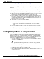
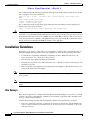
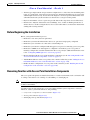
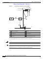
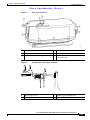
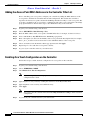
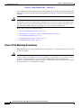
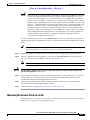
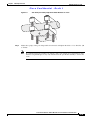
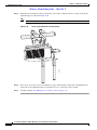
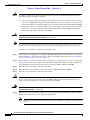
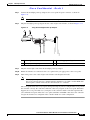
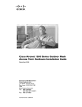
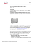
Cisco Conf idential - Draft 1
CH A P T E R
2
Mounting Instructions
This chapter describes warnings, safety information, and mounting information needed during the
installation of your access point. The chapter contains these sections:
•
Unpacking the Access Point, page 2-2
•
Tools and Materials, page 2-2
•
Warnings, page 2-3
•
Safety Information, page 2-3
•
Installation Guidelines, page 2-6
•
Mounting the Access Point, page 2-11
Cisco Aironet 1500 Series Outdoor Mesh Access Point Hardware Installation Guide
OL-9977-05
2-1
Chapter 2
Mounting Instructions
Unpacking the Access Point
Cisco Conf idential - Draft 1
Unpacking the Access Point
Note
When you are unpacking the access point, do not remove the foam blocks attached to the antenna
connectors. The foam protects the antenna connectors during installation.
Follow these steps to unpack the access point:
Step 1
Open the shipping container and carefully remove the contents.
Step 2
Return all packing materials to the shipping container and save it.
Step 3
Ensure that all items listed in Package Contents are included in the shipment. If any item is damaged or
missing, notify your authorized Cisco sales representative.
Package Contents
Each access point package contains the following items:
•
Access point with mounting plate attached
•
Cisco product documentation, translated safety warnings, registration and feedback cards
•
Grounding lug with screw and lock washer
Tools and Materials
To install the access point you will need the following:
•
Open and box-end wrenches or socket set and ratchet
•
Customer-supplied 10-AWG copper ground wire
•
Ground lug (Panduit PN-10-6R-2K) and screw with lock washer (supplied)
•
Customer supplied crimping tool for the ground lug (Panduit PN-10-6R-2K)
•
Optional power injector (AIR-PWRINJ1500=)
•
Optional Ethernet cable
– 150-ft (45.72-m) Ethernet cable (AIR-ETH1500-150=)
– Other lengths (user supplied)
•
Optional AC power cord
– 15-ft (4.6-m) power cord (AIR-CORD1500-15NA=) for use in the US and Canada.
– 40-ft (12.2-m) power cord (AIR-CORD1500-40NA=) for light pole installations in the US and
Canada.
– 40-ft (12.2-m) power cord (AIR-CORD1500-40UE=) for use outside the US and Canada. One
end of the power cord is terminated with an access point AC power connector and the other end
is unterminated.
Cisco Aironet 1500 Series Outdoor Mesh Access Point Hardware Installation Guide
2-2
OL-9977-05
Chapter 2
Mounting Instructions
Warnings
Cisco Conf idential - Draft 1
– 4-ft (1.2-m) streetlight power tap adapter (AIR-PWR-ST-LT-TAP=) for light pole installations
in the US and Canada.
•
Optional pole mount kit (AIR-ACCPMK1500=)
•
External antennas, 2.4 and 5 GHz (refer to the “External Antennas” section on page 1-3)
•
Optional primary protector (user supplied), as required by local regulations
•
Optional ladder, power lift, rope, or other tools as required
Warnings
Translated versions of all safety warnings are available in the safety warning document that shipped with
your access point or on Cisco.com. To browse to the document on Cisco.com, refer to Appendix 1,
“Translated Safety Warnings” for instructions.
Warning
IMPORTANT SAFETY INSTRUCTIONS
This warning symbol means danger. You are in a situation that could cause bodily injury. Before you
work on any equipment, be aware of the hazards involved with electrical circuitry and be familiar
with standard practices for preventing accidents. Use the statement number provided at the end of
each warning to locate its translation in the translated safety warnings that accompanied this device.
Statement 1071
SAVE THESE INSTRUCTIONS
Warning
Do not operate the unit near unshielded blasting caps or in an explosive environment unless the
device has been modified to be especially qualified for such use. Statement 364
Warning
This equipment must be externally grounded using a customer-supplied ground wire before power is
applied. Contact the appropriate electrical inspection authority or an electrician if you are uncertain
that suitable grounding is available. Statement 366
Warning
Read the installation instructions before connecting the system to the power source. Statement 1004
Warning
Ultimate disposal of this product should be handled according to all national laws and regulations.
Statement 1040
Safety Information
Follow the guidelines in this section to ensure proper operation and safe use of the access point.
Cisco Aironet 1500 Series Outdoor Mesh Access Point Hardware Installation Guide
OL-9977-05
2-3
Chapter 2
Mounting Instructions
Safety Information
Cisco Conf idential - Draft 1
FCC Safety Compliance Statement
The FCC, with its action in ET Docket 96-8, has adopted a safety standard for human exposure to RF
electromagnetic energy emitted by FCC-certified equipment. When used with approved Cisco Aironet
antennas, Cisco Aironet products meet the uncontrolled environmental limits found in OET-65 and ANSI
C95.1, 1991. Proper operation of this radio device according to the instructions in this publication results
in user exposure substantially below the FCC recommended limits.
Safety Precautions
Warning
In order to comply with radio frequency (RF) exposure limits, the antennas for this product should be
positioned no less than 6.56 ft (2 m) from your body or nearby persons. Statement 339
Warning
The AC power supply has double pole/neutral fusing. Statement 188
Warning
Do not work on the system or connect or disconnect cables during periods of lightning activity.
Statement 1001
Warning
This equipment has been designed for connection to TN and IT power systems. Statement 1007
Warning
Only trained and qualified personnel should be allowed to install, replace, or service this equipment.
Statement 1030
Warning
Do not locate the antenna near overhead power lines or other electric light or power circuits, or
where it can come into contact with such circuits. When installing the antenna, take extreme care
not to come into contact with such circuits, because they may cause serious injury or death. For
proper installation and grounding of the antenna, please refer to national and local codes (for
example, U.S.:NFPA 70, National Electrical Code, Article 810, Canada: Canadian Electrical Code,
Section 54). Statement 1052
Caution
No serviceable parts inside. Do not open.
Caution
Double pole/neutral fusing. The power supply has two fuses and might have live circuits even when one fuse
has blown.
Note
For additional important safety instructions for AC power cords, refer to the AC Power Cords for Cisco
Aironet 1500 Series Outdoor Mesh Access Points document that shipped with your AC power cords.
Cisco Aironet 1500 Series Outdoor Mesh Access Point Hardware Installation Guide
2-4
OL-9977-05
Chapter 2
Mounting Instructions
Avoiding Damage to Radios in a Testing Environment
Cisco Conf idential - Draft 1
Each year hundreds of people are killed or injured when attempting to install an antenna. In many of
these cases, the victim was aware of the danger of electrocution, but did not take adequate steps to avoid
the hazard.
For safety, and to help you achieve a good installation, please read and follow these safety precautions.
They may save your installer’s life!
1.
Select your installation site with safety, as well as performance in mind. Remember: electric power
lines and phone lines look alike. For safety, assume that any overhead line can kill.
2.
Call your electric power company. Tell them your plans and ask them to come look at your proposed
installation. This is a small inconvenience considering your installer’s life is at stake.
3.
Plan your installation carefully and completely before you begin. Successful raising of a mast or
tower is largely a matter of coordination. Each person should be assigned to a specific task, and
should know what to do and when to do it. One person should be in charge of the operation to issue
instructions and watch for signs of trouble.
4.
When installing the access point and antennas, remember:
a. Do not use a metal ladder.
b. Do not work on a wet or windy day.
c. Do dress properly—shoes with rubber soles and heels, rubber gloves, long sleeved shirt or
jacket.
5.
Use a rope to lift the access point. If the assembly starts to drop, get away from it and let it fall.
6.
If any part of the antenna system should come in contact with a power line, don’t touch it or try to
remove it yourself. Call your local power company. They will remove it safely.
If an accident should occur call for qualified emergency help immediately.
Avoiding Damage to Radios in a Testing Environment
The radios on outdoor units (bridges) have higher transmit power levels than radios on indoor units
(access points). When you test high power radios in a link, you must avoid exceeding the receiver’s
maximum receive input level. At levels above normal the operating range, packet error rate (PER)
performance is degraded. At even higher levels, the receiver can be permanently damaged. To avoid
receiver damage and PER degradation, you can use one of the following techniques:
•
Separate the omnidirectional antennas by at least 2 ft (0.6 m) to avoid receiver damage or by at least
25 ft (7.6 m) to avoid PER degradation.
Note
These distances assume free space path loss and are conservative estimates. Required
separation distances for damage and performance degradation levels in actual deployments will be less
due to non line-of-sight propagation conditions.
•
Reduce the configured transmit power to the minimum level.
•
Use directional antennas and keep them away from each other.
•
Cable the radios together using a combination of attenuators, combiners, or splitters to achieve a total
attenuation of at least 60 dB.
Cisco Aironet 1500 Series Outdoor Mesh Access Point Hardware Installation Guide
OL-9977-05
2-5
Chapter 2
Mounting Instructions
Installation Guidelines
Cisco Conf idential - Draft 1
For a radiated test bed, the following equation describes the relationships among transmit power, antenna
gain, attenuation, and receiver sensitivity:
txpwr +
Where:
txpwr =
tx gain
rx gain
tx gain + rx gain - [attenuation due to antenna spacing] < max rx input level
Radio transmit power level
= transmitter antenna gain
= receiver antenna gain
For a conducted test bed, the following equation describes the relationships among transmit power,
antenna gain, and receiver sensitivity:
txpwr - [attenuation due to coaxial components] < max rx input level
Caution
Under no circumstances should you connect the antenna port from one access point to the antenna port
of another access point without using an RF attenuator. If you connect antenna ports you must not exceed
the maximum survivable receive level of 0 dBm. Never exceed 0 dBm or damage to the access point can
occur. Using attenuators, combiners, and splitters having a total of at least 60 dB of attenuation ensures
that the receiver is not damaged and PER performance is not degraded.
Installation Guidelines
Because the access point is a radio device, it is susceptible to common causes of interference that can
reduce throughput and range. Follow these basic guidelines to ensure the best possible performance:
•
For information on planning and initially configuring your Cisco Mesh network, refer to the
Deployment Guide: Cisco Mesh Networking Solution.
•
Perform a site survey before beginning the installation.
•
Install the access point in an area where structures, trees, or hills do not obstruct radio signals to and
from the access point.
•
The access points can be installed at any height, but best throughput is achieved when all the access
points are mounted at the same height.
Note
Cisco recommends installing the access points no higher than 40 feet to allow support for wireless clients
on the ground.
Note
To calculate path loss and to determine how far apart to install access points, consult an RF planning
expert.
Site Surveys
Every network application is a unique installation. Before installing multiple access points, you should
perform a site survey to determine the optimum use of networking components and to maximize range,
coverage, and network performance.
Consider the following operating and environmental conditions when performing a site survey:
•
Data rates—Sensitivity and range are inversely proportional to data bit rates. The maximum radio
range is achieved at the lowest workable data rate. A decrease in receiver sensitivity occurs as the
radio data increases.
Cisco Aironet 1500 Series Outdoor Mesh Access Point Hardware Installation Guide
2-6
OL-9977-05
Chapter 2
Mounting Instructions
Installation Guidelines
Cisco Conf idential - Draft 1
•
Antenna type and placement—Proper antenna configuration is a critical factor in maximizing radio
range. As a general rule, range increases in proportion to antenna height. However, do not place the
antenna higher than necessary, because the extra height also increases potential interference from
other unlicensed radio systems and decreases the wireless coverage from the ground.
•
Physical environment—Clear or open areas provide better radio range than closed or filled areas.
•
Obstructions—Physical obstructions such as buildings, trees, or hills can hinder performance of
wireless devices. Avoid locating the devices in a location where there is an obstruction between the
sending and receiving antennas.
Before Beginning the Installation
Before you begin the installation process:
•
Ensure that a site survey has been performed.
•
Ensure that your network infrastructure devices are operational and properly configured.
•
Ensure that your controllers are connected to switch trunk ports.
•
Ensure that your switch is configured with untagged access ports for connecting your access points.
•
Ensure that a DHCP server with Option 43 configured is reachable by your access points or
manually configure the controller information in the access point (for additional information, refer
to the “Configuring DHCP Option 43” section on page G-1).
•
Become familiar with the access point installation components (see the “Becoming Familiar with
Access Point Installation Components” section on page 2-7).
•
Add the MAC addresses of the access points to the controller’s filter list (see the “Adding the Access
Point MAC Addresses to the Controller Filter List” section on page 2-10).
•
Enable automatic configuration of access points on the controller (see the “Enabling Zero Touch
Configuration on the Controller” section on page 2-10).
Becoming Familiar with Access Point Installation Components
The access point is designed to be installed in an indoor or outdoor environment, such as an interior wall
or ceiling or the exterior roof overhang of a tall building or a streetlight pole.
Note
When you mount access point in an indoor environment, you must also mount the attached antennas in
an indoor environment.
Carefully review the following figures to become familiar with the system components, connectors,
indicators, cables, system interconnection, and grounding:
•
Components in a Typical Access Point Installation (Figure 2-1)
•
Access point connectors (Figure 2-2)
•
Streetlight power tap installation (Figure 2-3)
Cisco Aironet 1500 Series Outdoor Mesh Access Point Hardware Installation Guide
OL-9977-05
2-7
Chapter 2
Mounting Instructions
Installation Guidelines
Cisco Conf idential - Draft 1
Figure 2-1
Components in a Typical Access Point Installation
1
2
9
10
8
3
7
142678
4
5
6
1
Building roof-overhang
1
6
Ground
7
AC power cord2
2
Outdoor rated shielded Ethernet cable
3
Water drip loop
8
Power injector3
4
10-AWG copper grounding wire1
9
Ethernet (CAT 5) cable1
5
Ground rod1
10 Controller (through a switch)
1. User supplied.
2. The safety ground wire in the AC power cord must have a ground path to a grounding rod.
3. The shielded Ethernet cable has a ground path through the power injector and the safety ground wire in the AC power cord.
Warning
Note
Installation of the equipment must comply with local and national electrical codes. Statement 1074
There is no requirement for external lightening arrestors on the 1510. The power supplies on the 1510
and the PoE in ports have transient voltage surge suppression. In addition, the PoE in port should be used
with shielded cables that are grounded at the access point and power injector.
Cisco Aironet 1500 Series Outdoor Mesh Access Point Hardware Installation Guide
2-8
OL-9977-05
Chapter 2
Mounting Instructions
Installation Guidelines
Cisco Conf idential - Draft 1
Figure 2-2
Access Point Connectors
1
5.8-GHz antenna bracket (LAP1510 model)
4
Ethernet (PoE) connector (MS3112P14-12P)
2
Vent (do not remove)
5
AC power connector (MS3112P14-5P)
3
2.4-GHz antenna connector (Type-N)
6
5.8-GHz Type N antenna connector
(LAP1510 model)
Figure 2-3
1
Streetlight Power Tap Adapter Installation
2
142680
3
1
Outdoor light control
2
Streetlight power tap adapter
3
10-AWG copper grounding wire
Cisco Aironet 1500 Series Outdoor Mesh Access Point Hardware Installation Guide
OL-9977-05
2-9
Chapter 2
Mounting Instructions
Installation Guidelines
Cisco Conf idential - Draft 1
Adding the Access Point MAC Addresses to the Controller Filter List
Prior to installing your access points, configure your controller by adding the MAC addresses of the
access points to the filter list and enable Zero Touch Configuration. This enables the controller to
respond to the listed access points and transfer the Bridge Shared Secret Key to each access point. The
secret key is required for the access points to communicate with other access points in the same bridge
group upon installation. Follow these steps to add a MAC filter entry on the controller:
Step 1
Log into your controller using a web browser.
Step 2
Choose SECURITY > MAC Filtering > New.
Step 3
Enter the MAC address of the access point to the MAC Filter list; for example, 00:0B:91:21:3A:C7.
Step 4
Select a WLAN ID or Any WLAN from the WLAN ID pop-up menu.
Step 5
Enter a description (32 characters maximum) of the access point in the Description field; for example,
Fisher_Street_00.0B.91.21.3A.C7 shows the location and MAC address of the access point.
Step 6
Choose an interface from the Interface Name pop-up menu and click Apply.
Step 7
Repeat Steps 2 to 6 to add other access points to the list.
Step 8
Log out of your controller and close your web browser.
Enabling Zero Touch Configuration on the Controller
Follow these steps to enable automatic configuration of access points on the controller:
Step 1
Log into your controller using a web browser.
Step 2
Choose WIRELESS > MESH.
Step 3
Check Enable Zero Touch Configuration.
Note
If you do not specify a new bridging shared secret key and key format, the default or the existing
configured value is used.
Step 4
[Optional] Choose a key format by clicking the down arrow in the Key Format field.
Step 5
[Optional] Enter a new secret key and confirm the entry.
Step 6
Click Apply.
Note
Step 7
You can also use the controller CLI command config network zero-config to enable automatic
configuration.
Log out from your controller and close your web browser.
Cisco Aironet 1500 Series Outdoor Mesh Access Point Hardware Installation Guide
2-10
OL-9977-05
Chapter 2
Mounting Instructions
Mounting the Access Point
Cisco Conf idential - Draft 1
Configuring a RAP
The access point defaults to the MAP radio role. One or more of your access points must be reconfigured
as a RAP. The RAPs connect to a wired Ethernet link through a switch to the controller. The MAPs use
their wireless backhaul interface to connect to a RAP to reach the controller.
Follow these steps to configure a RAP on the controller:
Step 1
Log into your controller using a web browser.
Step 2
Click Wireless. When your access point associates to the controller, your access point’s name is visible
in the AP Name list.
Step 3
Find your access point’s name and click Detail.
Step 4
Find Bridging Instructions and choose Root AP by clicking the drop down arrow in the AP Role field.
Step 5
Click Apply.
Step 6
Repeat Steps 2 through 5 for each RAP.
Step 7
Log out from your controller and close your web browser.
Mounting the Access Point
This section provides instructions for installing your access points. Personnel installing the access point
must understand wireless access points and bridging techniques and grounding methods.
Installation Options
There are two common installation methods: a roof-overhang or wall installation using the access point
mounting plate (supplied) or a pole installation using the optional pole mount kit.
Warning
Only trained and qualified personnel should be allowed to install, replace, or service this equipment.
Statement 1030
Warning
Installation of the equipment must comply with local and national electrical codes. Statement 1074
Caution
When the product is installed outside of the building, and the DC power/Ethernet connection is used, this
cabling should be installed in accordance with the requirements of a Class 2 circuit, as detailed in Article
725 of the National Electric Code (NEC). Such requirements include, but are not limited to, routing the
Class 2 cabling away from AC power lines and AC building wiring, and limiting the exposed cable runs
external to the building to less than 140 ft (42m) – or is directly buried or in underground conduit, where
a continuous metallic cable shield or a continuous metallic conduit containing the cable is bonded to
each building grounding electrode system. If such installation methods are not followed, the cabling
must be installed according to the requirements for telecommunication circuits (TNV) as detailed in
Cisco Aironet 1500 Series Outdoor Mesh Access Point Hardware Installation Guide
OL-9977-05
2-11
Chapter 2
Mounting Instructions
Mounting the Access Point
Cisco Conf idential - Draft 1
Article 800, which includes requirements for a Listed primary protector upon entering the building, and
limits the installation to only Listed networking equipment designed to accommodate telecommunication
interfaces.
Caution
To provide inline PoE, you must use the power injector (AIR- PWRINJ1500=) specified for the access
point. Other power injectors, PoE switches, and 802.3af power sources may not provide adequate power,
which may cause the access point to malfunction and cause over-current conditions at the power source.
You must ensure that the switch port connected to the access point has PoE turned off.
Refer to these sections for installation details.
•
Access Point Mounting Orientations, page 2-12
•
Mounting the Access Point on a Vertical or Horizontal Surface, page 2-15
•
Roof-Overhang Installation, page 2-16
•
Mounting the Access Point on a Pole, page 2-17
•
Streetlight Pole Installations, page 2-21
Access Point Mounting Orientations
When installing an access point on a horizontal or vertical surface, you must ensure that the access point
is correctly oriented.
Caution
When mounting the access point in a horizontal position, you must position the side with the 2.4-GHz
antenna connector facing down (see Figure 2-4). When you are mounting the access point in a vertical
position, you must position the access point with the 5-GHz antenna connector facing up (see
Figure 2-5). This positioning is required to prevent water intrusion into the unit from the vent. You must
ensure that the vent is not obstructed by anything.
Cisco Aironet 1500 Series Outdoor Mesh Access Point Hardware Installation Guide
2-12
OL-9977-05
Chapter 2
Mounting Instructions
Mounting the Access Point
Cisco Conf idential - Draft 1
Figure 2-4
Preferred Horizontal Orientation
1
2
142681
3
1
5-GHz antenna connector (LAP1510 model)
2
5-GHz antenna cable (LAP1510 model)
3
2.4-GHz antenna connector (this side down)
Cisco Aironet 1500 Series Outdoor Mesh Access Point Hardware Installation Guide
OL-9977-05
2-13
Chapter 2
Mounting Instructions
Mounting the Access Point
Cisco Conf idential - Draft 1
Figure 2-5 illustrates the access point vertical orientation.
Figure 2-5
Optional Vertical Orientation
1
142682
2
3
Note
1
5-GHz external antenna connector
(LAP 1510 model)
2
2.4-GHz external antenna connector
3
This end must be down
Omnidirectional antennas must be mounted vertically.
Cisco Aironet 1500 Series Outdoor Mesh Access Point Hardware Installation Guide
2-14
OL-9977-05
Chapter 2
Mounting Instructions
Mounting the Access Point
Cisco Conf idential - Draft 1
Mounting the Access Point on a Vertical or Horizontal Surface
To mount the access point on a vertical or horizontal surface such as a wall or a roof-overhang, use the
supplied mounting plate. For the correct access point mounting orientations, refer to the “Access Point
Mounting Orientations” section on page 2-12.
Step 1
The mounting plate is attached to the access point by two carriage bolts. Refer to Figure 2-6 for the
location of the carriage bolts securing the mounting plate.
Figure 2-6
Access Point Mounting Plate and Carriage Bolts
2
1
3
1
Mounting plate
2
Carriage bolts
170061
2
3
Grounding screw hole
Step 2
Remove the nuts and washers from the carriage bolts and remove the carriage bolts.
Step 3
Remove the mounting plate from the access point.
Cisco Aironet 1500 Series Outdoor Mesh Access Point Hardware Installation Guide
OL-9977-05
2-15
Chapter 2
Mounting Instructions
Mounting the Access Point
Cisco Conf idential - Draft 1
Step 4
Caution
Use the mounting plate as a template to mark four screw hole locations on your mounting surface. See
Figure 2-7 for the mounting plate screw hole locations.
The mounting surface, attaching screws, and optional wall anchors must be able to support a 50 lbs
(22.7 kg) static weight.
Figure 2-7
Mounting Plate Screw Hole Locations
142684
1
1
Step 5
Four locations
Use four customer-supplied screws and optional screw anchors to attach the mounting plate to the
mounting surface.
Note
If necessary, use suitable screw anchors and an exterior-grade plywood backboard to mount the
access point to stucco, cement, or drywall.
Step 6
Use the carriage bolts and the associated nuts and washers to reattach the access point to the mounting
plate. Tighten the nuts to 61 to 71 in. lbs (6.89 to 8.02 Nm).
Step 7
Continue with the “Roof-Overhang Installation” section.
Roof-Overhang Installation
When your access point is mounted on a roof overhang, follow these steps to complete the installation:
Step 1
Review Figure 2-1 to identify the components needed for the installation.
Step 2
Connect a Category 5 Ethernet cable from your wired LAN network to the optional power injector.
Cisco Aironet 1500 Series Outdoor Mesh Access Point Hardware Installation Guide
2-16
OL-9977-05
Chapter 2
Mounting Instructions
Mounting the Access Point
Cisco Conf idential - Draft 1
Caution
When the product is installed outside of the building, and the DC power/Ethernet connection
is used, this cabling should be installed in accordance with the requirements of a Class 2
circuit, as detailed in Article 725 of the National Electric Code (NEC). Such requirements
include, but are not limited to, routing the Class 2 cabling away from AC power lines and AC
building wiring, and limiting the exposed cable runs external to the building to less than 140
ft (42 m) – or is directly buried or in underground conduit, where a continuous metallic cable
shield or a continuous metallic conduit containing the cable is bonded to each building
grounding electrode system. If such installation methods are not used, the cabling must be
installed according to the requirements for telecommunication circuits (TNV) as detailed in
Article 800, which includes requirements for a Listed primary protector upon entering the
building, and limits the installation to only Listed networking equipment designed to
accommodate telecommunication interfaces.
Use only the specified power injector (AIR-PWRINJ1500=) for the access point. This power injector is
designed to meet the power requirements of the access point and is a listed Class 2 Limited Power Source
(LPS).
Tip
To forward bridge traffic, add a switch between the power injector and controller. Refer to the
Deployment Guide: Cisco Mesh Networking Solution for more information.
Step 3
Ensure the antennas are connected to the access point before you apply power to the access point.
Step 4
Connect a shielded outdoor-rated Ethernet cable (such as AIR-ETH1500-150=) between the power
injector and the access point’s Ethernet connector (see Figure 2-2).
Note
Warning
You should hand-tighten the access point Ethernet cable connector until the connector locks.
Use the captive connector cap on the unused mil spec connector to prevent water intrusion and
possible safety hazards. Statement 362
Step 5
When using the optional Cisco external omnidirectional antennas, connect them to the access point as
shown in Figure 2-1. When using other Cisco external antennas, mount them as directed by the
installation documentation that shipped with the antennas.
Step 6
When using optional third-party external antennas, mount and connect them as described in the
installation documents that shipped with the antennas.
Step 7
Continue with the “Grounding the Access Point” section on page 2-21.
Mounting the Access Point on a Pole
When installing an access point on a pole or mast, you should use the optional Cisco pole mount kit. To
mount the access point on a pole, perform these steps:
Cisco Aironet 1500 Series Outdoor Mesh Access Point Hardware Installation Guide
OL-9977-05
2-17
Chapter 2
Mounting Instructions
Mounting the Access Point
Cisco Conf idential - Draft 1
Step 1
From the pole mount kit, use four of the supplied short bolts, lock washers, and flat washers to attach
the pole mount kit adjustment plate to the access point mounting plate as shown in Figure 2-8. Tighten
the bolts to 15 to 20 ft. lbs. (20 to 27 Nm).
Adjustment Plate Attached to the Mounting Plate
142686
Figure 2-8
Step 2
Select a mounting location. You can attach the access point to any pole from 1.66 to 3.35 in. (4.22 to
9.02 cm) in diameter.
Note
Step 3
If you will be using a streetlight power tap adapter, position the access point within 3 ft (1 m) of
the outdoor light control.
Loosely assemble the pole clamp components around the pole and thread the four long bolts into the
clamp adjustment plate. Figure 2-9 shows the pole clamp attached to a pole with the clamp adjustment
plate positioned on the bolts.
Cisco Aironet 1500 Series Outdoor Mesh Access Point Hardware Installation Guide
2-18
OL-9977-05
Chapter 2
Mounting Instructions
Mounting the Access Point
Cisco Conf idential - Draft 1
Pole Clamp and Clamp Adjustment Plate Mounted on a Pole
142687
Figure 2-9
Step 4
Adjust the top edge of the pole clamp until it is horizontal and tighten the bolts to 15 to 20 ft. lbs. (20
to 27 Nm)
Note
If you need longer bolts, purchase 3/8–16 bolts of the correct length for your installation. Also,
the bolts can protrude up to 2 in (5 cm) and still allow the pole mount assembly to swivel and
rotate.
Cisco Aironet 1500 Series Outdoor Mesh Access Point Hardware Installation Guide
OL-9977-05
2-19
Chapter 2
Mounting Instructions
Mounting the Access Point
Cisco Conf idential - Draft 1
Step 5
From the pole mount kit, use the two short bolts, lock washers, and flat washers to loosely attach the two
adjustment plates as shown in Figure 2-10.
Note
Do not over-tighten the bolts. You will need to adjust the access point orientation.
Access Point Attached to the Pole Clamp
142688
Figure 2-10
Step 6
If necessary, rotate the access point until the top edge of the housing is horizontal, and tighten the two
short bolts on the adjustment plates. Torque the bolts to 15 to 20 ft. lbs. (20 to 27 Nm).
Step 7
Continue with the “Grounding the Access Point” section on page 2-21.
Cisco Aironet 1500 Series Outdoor Mesh Access Point Hardware Installation Guide
2-20
OL-9977-05
Chapter 2
Mounting Instructions
Mounting the Access Point
Cisco Conf idential - Draft 1
Grounding the Access Point
Warning
This equipment must be externally grounded using a customer-supplied ground wire before power is
applied. Contact the appropriate electrical inspection authority or an electrician if you are uncertain
that suitable grounding is available. Statement 366
Warning
Installation of the equipment must comply with local and national electrical codes. Statement 1074
In all outdoor installations and when powering the access point with AC power, you must follow these
instructions to properly ground the case:
Step 1
If using insulated 10-AWG copper ground wire, strip the insulation as required for the grounding lug.
Step 2
Use the appropriate crimping tool to crimp the bare 10-AWG copper ground wire to the grounding lug
(Panduit PN-10-6R-2K lug supplied).
Step 3
Connect the grounding lug to the access point grounding screw hole using the supplied Phillips head
screw (6-32x1/4 stainless steel) with lock washer (McMaster-Carr 95345A458 or equivalent). The
grounding screw hole is located on the mounting plate side of the access point case near the 5-GHz
antenna connector (see Figure 2-6). Tighten the grounding screw to 7 to 8 in. lbs. Do not overtighten!
Step 4
If necessary, strip the other end of the ground wire and connect to a reliable earth ground, such as a
grounding rod or an appropriate grounding point on a metal streetlight pole that is grounded (see
Figure 2-1 and Figure 2-11).
Streetlight Pole Installations
The access point can be installed where power is available, without the need for a wired LAN connection.
The access point uses intelligent wireless routing that is based on the Adaptive Wireless Path Protocol
(AWPP). AWPP enables a remote access point to dynamically optimize the best route to the wired LAN
network using another access point.
The LAP1510 model uses the 5-GHz radio for the Mesh backhaul Mesh connections. The 2.4-GHz radio
is used for local wireless client access. The LAP1505 model uses the 2.4-GHz radio for both Mesh
backhaul and local wireless client access.
The access point can be installed on a streetlight pole and powered from a streetlight outdoor light
control using the optional streetlight power tap adapter.
Caution
The access point can be powered by a light pole twist-lock outdoor light control that provides 100- to
240-VAC 50/60 Hz power. Do not connect to an outdoor light control powered by higher voltages.
When powering the access point with AC power other than the streetlight power tap adapter, you must
ensure that the following conditions are observed:
1.
AC power can be conveniently removed from the unit. The power should not be removed by
disconnecting the AC power connector on the unit.
Cisco Aironet 1500 Series Outdoor Mesh Access Point Hardware Installation Guide
OL-9977-05
2-21
Chapter 2
Mounting Instructions
Mounting the Access Point
Cisco Conf idential - Draft 1
Caution
A readily accessible service disconnect device must be incorporated in the fixed wiring. The disconnect
device must open all of the phase conductors.
2.
You must protect any AC power plugs and AC receptacles from water and other outdoor elements.
You can accomplished by using a UL Listed waterproofing enclosure suitable for covering the AC
receptacle and AC power plug that supplies power to the unit as described in Article 406 of the NEC.
3.
When you install the access point outdoors or in a wet or damp location, the AC branch circuit that
powers the access point should be provided with ground fault protection (GFCI), as required by
Article 210 of the National Electrical Code (NEC).
Warning
Be very careful when connecting the streetlight adapter to Category 3 pole-top power. If you are not
careful, you may electrocute yourself or fall. Statement 363
Note
For additional important safety instructions for AC power cords, refer to the AC Power Cords for Cisco
Aironet 1500 Series Outdoor Mesh Access Points document that shipped with your AC power cords.
To install an access point on a light pole, follow these steps:
Step 1
When using the streetlight power tap adapter (AIR-PWR-ST-LT-TAP=), ensure that the access point is
mounted within 3 ft (1m) of the outdoor light control. For mounting instructions, refer to the “Mounting
the Access Point on a Pole” section on page 2-17.
Step 2
Refer to Figure 2-11. The streetlight power tap adapter uses a 3-pronged UL773 twist-lock adapter that
is placed between the outdoor light control and its fixture. The UL773 twist-lock adapter is designed to
be used with UL773 listed outdoor light controls operating at 100-to 240-VAC, 50/60 Hz.
Step 3
Disconnect the outdoor light control from its fixture.
Step 4
Verify that the voltage available at the fixture is between 100 and 240 VAC, 50/60 Hz.
Step 5
Turn off power to the fixture at the designated circuits.
Caution
Warning
Step 6
For your safety, when installing the streetlight power tap adapter to the access point AC power connector,
always connect the access point end of the cable FIRST. When removing the streetlight power tap
adapter, always disconnect the access point end of the cable LAST.
Use the captive connector cap on the unused mil spec connector to prevent water intrusion and
possible safety hazards. Statement 362
Move the protective cap from the 5-pin AC power connector to the 12-pin Ethernet connector because
the Ethernet connector is not used in light pole deployments.
Note
Ensure that your antennas are connected to the access point before you apply power to the access
point.
Cisco Aironet 1500 Series Outdoor Mesh Access Point Hardware Installation Guide
2-22
OL-9977-05
Chapter 2
Mounting Instructions
Mounting the Access Point
Cisco Conf idential - Draft 1
Step 7
Connect the streetlight power tap adapter to the access point AC power connector, as shown in
Figure 2-11.
Hand-tighten the cable connector until it locks. No specific torque is required.
Note
Step 8
Plug the streetlight power tap adapter into the outdoor light control fixture, as shown in Figure 2-11.
Figure 2-11
1
Using the Streetlight Power Tap Adapter
2
142680
3
1
Outdoor light control
2
Streetlight power tap adapter
3
10-AWG copper grounding wire
Step 9
Plug the outdoor light control into the streetlight power tap adapter.
Step 10
Ensure the antennas are connected to the access point before you apply power to the access point.
Step 11
Turn on the power to the outdoor light control fixture at the designated circuits.
Note
When you power up a MAP that is not connected to a wired Ethernet network to the controller,
the access point uses the Cisco Adaptive Wireless Path Protocol to bind to another MAP with
the best path to a RAP connected to the wired network to a controller.
The access point sends a discovery request when powered up. If you have configured the access point in
the controller correctly, the controller sends back a discovery response to the access point. When that
happens, the access point sends out a join request to the controller and the controller responds with a
join confirmation response. Then, the access point establishes an LWAPP connection to the controller
and gets the shared secret configured on the controller under zero-touch configuration.
Cisco Aironet 1500 Series Outdoor Mesh Access Point Hardware Installation Guide
OL-9977-05
2-23
Chapter 2
Mounting Instructions
Mounting the Access Point
Cisco Conf idential - Draft 1
What to Do Next
Refer to the Cisco Wireless LAN Controller Configuration Guide for more information on configuring,
monitoring, and operating your access points. The following lists some of the configuration settings you
might want to reconfigure:
•
Changing the bridge shared secret key to a non-default value
•
Selecting a backhaul channel when using the 4.9 MHz band ( LAP1510 model only)
•
Disabling the Zero Touch Configuration feature
Cisco Aironet 1500 Series Outdoor Mesh Access Point Hardware Installation Guide
2-24
OL-9977-05