1
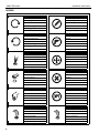
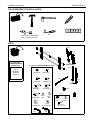
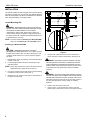
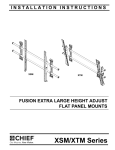
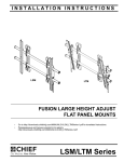
INSTALLATION INSTRUCTIONS
Instrucciones de instalación
Installationsanleitung
Instruções de Instalação
XSM
Istruzioni di installazione
Installatie-instructies
Instructions d´installation
XTM
FUSION EXTRA LARGE HEIGHT ADJUST
FLAT PANEL MOUNTS
XSM/XTM Series
XSM/XTM Series
Installation Instructions
DISCLAIMER
Milestone AV Technologies, and its affiliated corporations and
subsidiaries (collectively "Milestone"), intend to make this
manual accurate and complete. However, Milestone makes no
claim that the information contained herein covers all details,
conditions or variations, nor does it provide for every possible
contingency in connection with the installation or use of this
product. The information contained in this document is subject
to change without notice or obligation of any kind. Milestone
makes no representation of warranty, expressed or implied,
regarding the information contained herein. Milestone assumes
no responsibility for accuracy, completeness or sufficiency of
the information contained in this document.
Chief® is a registered trademark of Milestone AV Technologies.
All rights reserved.
IMPORTANT WARNINGS AND
CAUTIONS!
CAUTION: A CAUTION alerts you to the possibility of
damage or destruction of equipment if you do not follow the
corresponding instructions.
WARNING: Failure to read, thoroughly understand, and
follow all instructions can result in serious personal injury,
damage to equipment, or voiding of factory warranty! It is the
installer’s responsibility to make sure all components are
properly assembled and installed using the instructions
provided.
WARNING: Failure to provide adequate structural strength
for this component can result in serious personal injury or
damage to equipment! It is the installer’s responsibility to
make sure the structure to which this component is attached
can support five times the combined weight of all equipment.
Reinforce the structure as required before installing the
component.
WARNING: Exceeding the weight capacity can result in
WARNING: A WARNING alerts you to the possibility of
serious injury or death if you do not follow the instructions.
2
serious personal injury or damage to equipment! It is the
installer’s responsibility to make sure the combined weight of
all components attached to the XSM/XTM up to (and
including) the display does not exceed 250 lbs (113.4 kg).
Installation Instructions
XSM/XTM Series
DIMENSIONS
XSM
MAX MOUNTING PATTERN IS 46" (1168.4 mm) WITHOUT REVERSING UPRIGHTS
WITH REVERSING THE UPRIGHTS
MAX MOUNTING PATTERN IS 48.4" (1229.4 mm)
24.3
.96
MINIMUM UPRIGHT SPACING
24"
25.4
1.00
0
10.2
.40
45
1.77
90
3.54
105
4.13
73.9
2.91
38.4
1.51
12.9
.51
150
5.91
165
6.50
210
8.27
225
8.86
270
10.63
8.3
.33
285
11.22
51
2
383.4
15.10
44.5
1.75
419.6
16.52
685.8
27.00
330
12.99
345
13.58
405
15.94
RAILS CAN BE SLID LEFT
OR RIGHT FOR OFFSET
25.4
1.00
465
18.31
525
20.67
1232.7
48.53
585
23.03
630
24.80
660
25.98
MEASUREMENTS IN: [MILLIMETERS]
INCHES
XTM
WITH REVERSING THE UPRIGHTS
MAX MOUNTING PATTERN IS 49.2" (1249.7 mm)
10.2
.40
0
24.4
.96
12°
MAX TILT WILL VARY DEPENDING
UPON SCREEN SIZE
MINIMUM UPRIGHT SPACING
24"
25.4
1.00
74.1
2.92
12.9
.51
45
1.77
90
3.54
105
4.13
150
5.91
50.8
2.00
25.4
1.00
8.3
.33
165
6.50
210
8.27
225
8.86
44.5
1.75
383.4
15.10
670.8
26.41
419.6
16.52
270
10.63
285
11.22
685.8
27.00
330
12.99
345
13.58
RAILS CAN BE SLID LEFT
OR RIGHT FOR OFFSET
405
15.94
465
18.31
1232.8
48.54
525
20.67
585
23.03
MEASUREMENTS IN: [MILLIMETERS]
INCHES
630
24.80
660
25.98
3
XSM/XTM Series
Installation Instructions
LEGEND
4
Tighten Fastener
Pencil Mark
Apretar elemento de fijación
Marcar con lápiz
Befestigungsteil festziehen
Stiftmarkierung
Apertar fixador
Marcar com lápis
Serrare il fissaggio
Segno a matita
Bevestiging vastdraaien
Potloodmerkteken
Serrez les fixations
Marquage au crayon
Loosen Fastener
Drill Hole
Aflojar elemento de fijación
Perforar
Befestigungsteil lösen
Bohrloch
Desapertar fixador
Fazer furo
Allentare il fissaggio
Praticare un foro
Bevestiging losdraaien
Gat boren
Desserrez les fixations
Percez un trou
Phillips Screwdriver
Adjust
Destornillador Phillips
Ajustar
Kreuzschlitzschraubendreher
Einstellen
Chave de fendas Phillips
Ajustar
Cacciavite a stella
Regolare
Kruiskopschroevendraaier
Afstellen
Tournevis à pointe cruciforme
Ajuster
Open-Ended Wrench
Remove
Llave de boca
Quitar
Gabelschlüssel
Entfernen
Chave de bocas
Remover
Chiave a punte aperte
Rimuovere
Steeksleutel
Verwijderen
Clé à fourche
Retirez
By Hand
Optional
A mano
Opcional
Von Hand
Optional
Com a mão
Opcional
A mano
Opzionale
Met de hand
Optie
À la main
En option
Hex-Head Wrench
Security Wrench
Llave de cabeza hexagonal
Llave de seguridad
Sechskantschlüssel
Sicherheitsschlüssel
Chave de cabeça sextavada
Chave de segurança
Chiave esagonale
Chiave di sicurezza
Zeskantsleutel
Veiligheidssleutel
Clé à tête hexagonale
Clé de sécurité
Installation Instructions
XSM/XTM Series
TOOLS REQUIRED FOR INSTALLATION
#2
7/32" (5.5mm) Wood Stud
5/16" (7.9mm) Concrete
PARTS
B (1)
C (1)
A (1)
[Included with
XSM2XXX/XTM2XXX
Models Only]
(XTM Only)
J (1) [Used on XSMU/XTMU Models Only]
E (1)
Custom
XSM2XXX/
XTM2XXX
Hardware
J1 (6)
M6x16mm
J3 (6)
M8x20mm
J2 (6)
M6x25mm
J4 (6)
M8x30mm
G (1)
F (1)
(XSM Only)
J5 (4)
M8x50mm
J6 (6)
M10x40mm
H (4)
K (1)
J7 (6)
M10x50mm
J10 (6)
1.00x.400x.75"
J12 (1)
M5
J8 (6)
M6
J9 (6)
M8
J11 (6)
.750x.323x.250"
K1 (4)
5/16"
K2 (4)
5/16"
L (1)
K3 (4)
5/16" x 2-1/2"
J13 (1)
M6
5
XSM/XTM Series
Installation Instructions
INSTALLATION
Center of screen
The XTM and XSM have been designed to be mounted directly
onto either a wood stud or concrete wall. The XTM has brackets
which allow the display to be tilted. The XSM has static brackets
which keep the display in an upright position.
7-1/2"
Locate Mounting Site
WARNING: IMPROPER INSTALLATION CAN LEAD TO
MOUNT FALLING CAUSING SEVERE PERSONAL INJURY
OR DAMAGE TO EQUIPMENT! It is the installers
responsibility to make certain the structure to which the
mount is being attached is capable of supporting five times
the weight of the XTM or XSM and all attached equipment not
to exceed 250 lbs (113.4 kg).
Vertical center
of mount
NOTE: Proceed to either the Installing to a Wood Stud Wall
section or the Installing to a Concrete Wall section.
Installing to a Wood Stud Wall
CAUTION: MINIMUM HORIZONTAL DISTANCE
BETWEEN WALL BRACKETS IS 24". Do not place mounting
brackets closer together than 24". When attaching to a wall
containing studs located 16" on center, space the uprights
32" apart.
1.
2.
Figure 1
5.
Determine the center of the display, and where it should be
located on the wall.
WARNING: ELECTRICAL SHOCK HAZARD! CUTTING
OR DRILLING INTO ELECTRICAL CORDS OR CABLES
CAN CAUSE DEATH OR SERIOUS PERSONAL INJURY!
ALWAYS make certain area behind mounting surface is free
of electrical wires and cables before drilling or installing
fasteners.
Locate the appropriate studs to the left and right of the
selected location.
NOTE: If the screen area lies over a stud, use that stud and an
appropriate stud to either the left or right of it.
3.
Line up the notches on mount with center of screen marking
to determine vertical center. (See Figure 1)
4.
Measure up 7-1/2" from the center point to mark location of
the upper mounting slots.
6
Using a level, mark the wall on each stud to attach the
mount through the upper mounting slots. (See Figure 2)
WARNING: EXPLOSION AND FIRE HAZARD! CUTTING
OR DRILLING INTO GAS PLUMBING CAN CAUSE DEATH
OR SERIOUS PERSONAL INJURY! ALWAYS make certain
area behind mounting surface is free of gas, water, waste, or
any other plumbing before cutting, drilling, or installing
fasteners.
6.
Drill one 7/32" pilot hole in each stud.
7.
Use two 5/16 x 2-1/2" lag bolts (K3) and two 5/16" flat
washers (K2) to attach top of mount to wall. (See Figure 2)
Installation Instructions
XSM/XTM Series
WARNING: EXPLOSION AND FIRE HAZARD! CUTTING
5
OR DRILLING INTO GAS PLUMBING CAN CAUSE DEATH
OR SERIOUS PERSONAL INJURY! ALWAYS make certain
area behind mounting surface is free of gas, water, waste, or
any other plumbing before cutting, drilling, or installing
fasteners.
6
6 10
(K1) x 4
4
8
5
9
x4
7
10
(K3) x 4
8
9
(K2) x 4
Figure 2
8.
Mark the attachment points for the lower mounting slots,
making sure the attachment points are located on the studs.
(See Figure 2)
9. Drill 7/32" pilot holes at markings for lower mounting holes.
(See Figure 2)
10. Use two 5/16 x 2-1/2" lag bolts (K3) and two 5/16" flat
washers (K2) to attach the mount to the wall through the
lower mounting holes. (See Figure 2)
11. Slide rails to approximate center of screen location.
Installing to a Concrete Wall
CAUTION: MINIMUM HORIZONTAL DISTANCE
BETWEEN WALL BRACKETS IS 24". Do not place mounting
brackets closer together than 24".
7 11
(K3) x 4
(K2) x 4
Figure 3
5.
Drill one 5/16" pilot hole at each marking.
6.
Install an anchor (K1) into each pilot hole using a hammer.
7.
Use two 5/16 x 2-1/2" lag bolts (K3) and two 5/16" flat
washers (K2) to attach top of mount to anchors in wall.
8.
Mark the attachment points for the lower mounting slots.
(See Figure 3)
Drill one pilot hole at each marking for lower mounting
holes. (See Figure 3)
9.
1.
Determine the center of the display, and where it should be
located on the wall.
10. Install an anchor (K1) into each pilot hole using a hammer.
2.
Line up the notches on mount with center of screen marking
to determine vertical center. (See Figure 1)
11. Use two 5/16 x 2-1/2" lag bolts (K3) and two 5/16" flat
washers (K2) to attach the mount to the wall through the
lower mounting holes. (See Figure 3)
3.
Measure up 7-1/2" from the center point to mark location of
the upper mounting slots. (See Figure 1)
12. Slide rails to approximate center of screen location.
4.
Using a level, mark the wall through both upper mounting
slots. (See Figure 3)
WARNING: ELECTRICAL SHOCK HAZARD! CUTTING
OR DRILLING INTO ELECTRICAL CORDS OR CABLES
CAN CAUSE DEATH OR SERIOUS PERSONAL INJURY!
ALWAYS make certain area behind mounting surface is free
of electrical wires and cables before drilling or installing
fasteners.
Attaching Interface Brackets to Display
1.
Align the center of the bracket with center of screen.
(See Figure 4)
NOTE: The diamond-shape hole in the bracket corresponds to
the center of the mount.
7
XSM/XTM Series
Installation Instructions
1
Knobs
Center of bracket
Figure 4
WARNING: IMPROPER INSTALLATION CAN LEAD TO
2
DISPLAY FALLING CAUSING SERIOUS PERSONAL
INJURY OR DAMAGE TO EQUIPMENT! Using screws of
improper size may damage your display. Properly sized
screws will easily and completely thread into display
mounting holes. If spacers are required, be sure to use longer
screws of the same diameter.
2.
Select correct screws, spacers (if necessary) and washers
from the hardware bag and attach brackets to back of
screen. (See Figure 4)
Switching Interface Brackets (Optional)
If an installation situation makes adjusting the location of
interface brackets necessary, there are several options.
1.
The wall brackets may be adjusted side to side at the point
of attachment. (See Figure 5)
2.
The location of the left and right interface brackets may be
switched, with the knobs on the XTM interface brackets
facing the inside of the mount. (See Figure 5)
8
Figure 5
3.
If necessary, the tilt interface bracket knobs may be
switched to allow the interface brackets to be reversed.
(See Figure 6)
a. Remove display from mount.
b. Remove interface brackets from display.
c. Hold the right interface bracket horizontally, tightly
gripping it so that spacers do not move.
d. Remove the knob, washer and screw.
e. Replace the knob, washer and screw in the opposite
order, with the knob on the inside of the bracket.
f. Switch the right interface bracket to the left side of the
wall mount.
g. Repeat Steps 3c through 3f with the left interface
bracket.
Installation Instructions
XSM/XTM Series
Center Line (CL)
3d
3e
Pull strap
NEVER place both interface brackets to one
side of the wall mount center line (CL)!
Knobs to outside
of brackets
Figure 6
Attaching Screen to Wall Mount
1.
Attach wall bracket caps (H) to top and bottom of both wall
brackets. (See Figure 7)
Both interface brackets must NEVER be located
to one side of the wall brackets!
Figure 8
XTM Model
NOTE: Proceed to Step 8 for XSM Model instructions.
3.
(H) x 4
Hang top hook of interface brackets onto the top bar of the
mount. (See Figure 9)
NOTE: The screen initially installs into the "kickstand mode" to
allow easy cable access.
Figure 7
2.
Adjust Velcro® pull strap (if necessary) so it does not
extend beyond bottom of screen. (See Figure 8)
4.
Slide screen and bars to desired viewing position.
5.
Route cables between wall and bars.
NOTE: NEVER place both interface brackets to one side of the
wall mount center line! (See Figure 8)
CAUTION: PINCH POINTS! Keep fingers, hands and
NOTE: Do NOT allow both interface brackets to be located on
cables out of pinch point areas.
same side of wall bracket. (See Figure 8)
6.
Pull downward on the pullstraps and swing inward toward
wall, latching interface brackets to lower bar and locking
bottom of screen to the mount. (See Figure 9)
9
XSM/XTM Series
7.
Installation Instructions
Proceed to Adjusting Roll/Height of Wall Brackets
section.
(Screen not shown for clarity)
Top
Hook
10. Move screen towards the wall by pulling display bottom
away from wall and pushing the interface bracket tabs up
one notch to the detent which you will be able to feel
(approximately half way up).
11. Push bottom of display toward the wall bracket so that lower
latch on interface bracket surrounds lower bar of wall
mount.
12. Raise interface brackets tabs all the way to secure the
brackets onto the wall mount. (See Figure 10)
3
Adjusting Roll/Height of Wall Brackets
NOTE: The height adjust wall brackets allow adjustment of
+ 1/2".
1.
Turn to right (tighten) to raise side of screen.
(See Figure 11)
2.
Turn to left (loosen) to lower side of the screen.
1
Raises screen
2
Lowers screen
(G)
6
Pull straps
Figure 9
XSM Model
8.
Push interface bracket tab all the way down so that the
lower mounting slot is blocked. (See Figure 10)
(Screen not shown for clarity)
Figure 11
Latch
closed
Locking XTM Mount (Optional)
1.
Add optional security bracket (L) to the mount.
(See Figure 12)
2.
Add padlock (not included) to complete security.
(XTM Shown)
Latch
open
(L)
8
Interface
bracket
tab
2
10
1
12
Figure 10
9.
10
Hang the top hook of interface brackets onto the top bar of
the mount. The bottom of the screen will be away from the
wall.
Figure 12
Installation Instructions
XSM/XTM Series
Locking XSM Mount (Optional)
Add padlock (not included) to interface bracket tab to lock the
XSM mount. (See Figure 13)
Add padlock
Figure 13
11
XSM/XTM Series
Installation Instructions
USA/International
Europe
Chief Manufacturing, a products
division of Milestone AV Technologies
8805-000259
2008 Milestone AV Technologies,
a Duchossois Group Company
www.chiefmfg.com
11/08
Asia Pacific
A
P
F
A
P
F
A
8401 Eagle Creek Parkway, Savage, MN 55378
800.582.6480 / 952.894.6280
877.894.6918 / 952.894.6918
Fellenoord 130 5611 ZB EINDHOVEN, The Netherlands
+31 (0)40 2668620
+31 (0)40 2668615
Room 24F, Block D, Lily YinDu International Building
LuoGang, BuJi Town, Shenzhen, CHINA.
P +86-755-8996 9226
F +86-755-8996 9217