1
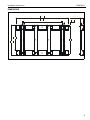
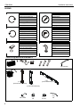
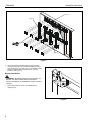
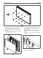
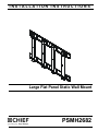
INSTALLATION INSTRUCTIONS
Instrucciones de instalación
Installationsanleitung
Instruções de Instalação
Istruzioni di installazione
Installatie-instructies
Instructions d´installation
Large Flat Panel Static Wall Mount
Spanish Product Description
German Product Description
Portuguese Product Description
Italian Product Description
Dutch Product Description
French Product Description
PSMH2682
PSMH2682
Installation Instructions
DISCLAIMER
Milestone AV Technologies and its affiliated corporations and
subsidiaries (collectively "Milestone"), intend to make this
manual accurate and complete. However, Milestone makes no
claim that the information contained herein covers all details,
conditions or variations, nor does it provide for every possible
contingency in connection with the installation or use of this
product. The information contained in this document is subject
to change without notice or obligation of any kind. Milestone
makes no representation of warranty, expressed or implied,
regarding the information contained herein. Milestone assumes
no responsibility for accuracy, completeness or sufficiency of
the information contained in this document.
Chief® is a registered trademark of Milestone AV Technologies.
All rights reserved.
IMPORTANT SAFETY INSTRUCTIONS!
WARNING: A WARNING alerts you to the possibility of
serious injury or death if you do not follow the instructions.
CAUTION: A CAUTION alerts you to the possibility of
damage or destruction of equipment if you do not follow the
corresponding instructions.
WARNING: Failure to read, thoroughly understand, and
follow all instructions can result in serious personal injury,
damage to equipment, or voiding of factory warranty! It is the
installer’s responsibility to make sure all components are
properly assembled and installed using the instructions
provided.
WARNING: Failure to provide adequate structural strength
for this component can result in serious personal injury or
damage to equipment! It is the installer’s responsibility to
make sure the structure to which this component is attached
can support a minimum of 2,000lbs (907.185kg). Reinforce
the structure as required before installing the component.The
wall to which the mount is being attached may have a
maximum drywall thickness of 5/8" (1.6cm). Do not install
drywall anchors into the seam between drywall pieces.
WARNING: Use this mounting system only for its intended
use as described in these instructions. Do not use
attachments not recommended by the manufacturer.
WARNING: Never operate this mounting system if it is
damaged. Return the mounting system to a service center for
examination and repair.
WARNING: Do not use this product outdoors.
2
WARNING: Exceeding the weight capacity can result in
serious personal injury or damage to equipment! It is the
installer’s responsibility to make sure the combined weight of
all components attached to the PSMH-2682 mount does not
exceed 320 lbs (119.44 kg).
--SAVE THESE INSTRUCTIONS--
Installation Instructions
PSMH2682
DIMENSIONS
1574.8
62.00
4.00
OFFSET FROM WALL
1200
47.24
749.3
29.50
47.9
1.89
800
31.50
895.8
35.27
3
PSMH2682
Installation Instructions
LEGEND
Tighten Fastener
Pencil Mark
Apretar elemento de fijación
Marcar con lápiz
Befestigungsteil festziehen
Stiftmarkierung
Apertar fixador
Marcar com lápis
Serrare il fissaggio
Segno a matita
Bevestiging vastdraaien
Potloodmerkteken
Serrez les fixations
Marquage au crayon
Loosen Fastener
Drill Hole
Aflojar elemento de fijación
Perforar
Befestigungsteil lösen
Bohrloch
Desapertar fixador
Fazer furo
Allentare il fissaggio
Praticare un foro
Bevestiging losdraaien
Gat boren
Desserrez les fixations
Percez un trou
Open-Ended Wrench
Hex-Head Wrench
Destornillador Phillips
Ajustar
Kreuzschlitzschraubendreher
Einstellen
Chave de fendas Phillips
Ajustar
Cacciavite a stella
Regolare
Kruiskopschroevendraaier
Afstellen
Tournevis à pointe cruciforme
Ajuster
TOOLS FOR INSTALLATION/PARTS
M5 (included)
A (2)
[Outside Vertical Bracket]
D (8)
M8 x 45mm
4
C (2)
[Horizontal Bracket]
B (2)
[Inside Vertical Bracket]
E(8)
M8
F (32)
5/16-18"
G (1)
M5
Installation Instructions
PSMH2682
ASSEMBLY AND INSTALLATION
8.
Secure horizontal brackets (C) to studs using appropriate
hardware for mounting surface. (See Figure 2)
Mount Installation
WARNING: IMPROPER INSTALLATION CAN LEAD TO
(C) x 2
DISPLAY FALLING CAUSING SERIOUS PERSONAL
INJURY OR DAMAGE TO EQUIPMENT! It is the installer’s
responsibility to make sure the structure to which this mount
is being attached can support a minimum of 2,000 lbs
(907.18kg). Reinforce the structure as required before
installing this mount.
1.
Raise upper horizontal bracket (C) against wall in desired
installation location. (See Figure 1)
2.
Level and adjust horizontal position making certain slots in
upper horizontal bracket on mount are properly positioned
over studs.
3.
Using a pencil, or similar marking tool, mark the location of
mounting holes in base onto surface. (See Figure 1)
4.
Hang two outside vertical brackets (A) from upper horizontal
bracket to determine mounting position for lower horizontal
bracket. (See Figure 1)
5.
Raise lower horizontal bracket (C) against wall in desired
installation location using vertical brackets to determine
distance from upper horizontal bracket. (See Figure 1)
6.
Mark the location of mounting holes for the lower horizontal
bracket in base onto surface. (See Figure 1)
7.
Drill eight pilot holes at marked locations. (See Figure 1)
8
Figure 2
NOTE: Pilot hole size will depend on the type and size of
fastener being used.
3
x4
7
x8
2
5
4
(A) x 2 (for reference, do not attach)
6
x4
Figure 1
5
PSMH2682
Installation Instructions
(C) x 2
(A) x 2
9
(F) x 32
(B) x 2
Figure 3
9.
Attach two outside vertical brackets (A) and two inside
vertical brackets (B) to two horizontal brackets (B) using
thirty-two 5/16-18" nylon lock nuts (F). The outside vertical
brackets installed must be attached as the outer two
brackets. (See Figure 3)
Display Installation
WARNING: IMPROPER INSTALLATION CAN LEAD TO
MOUNT FALLING CAUSING SERIOUS PERSONAL
INJURY OR DAMAGE TO EQUIPMENT! DO NOT substitute
hardware.
1.
OPEN
1
Move locking flags on mount to the OPEN position.
(See Figure 4)
Figure 4
6
Installation Instructions
PSMH2682
(E) x 8
2
(D) x 8
Figure 5
2.
Install eight mounting buttons (E) onto display using eight
M8 x 45 button head cap screws (D). (See Figure 5)
3.
Lift display following lifting instructions provided by display
manufacturer.
4.
5.
Move display forward until recessed area of mounting
buttons is positioned over lower area of teardrop mounting
holes. (See Figure 6)
6.
Lower display until recess area of mounting buttons is
seated in lower area of teardrop mounting holes. (See
Figure 6)
7.
Move locking flags to CLOSED position and lock if desired.
(See Figure 7)
Align mounting buttons on display with teardrop mounting
holes in mount. (See Figure 6)
padlock here
4
6
CLOSE
3
Figure 7
8.
Route wires and cables to display.
Figure 6
7
PSMH2682
Installation Instructions
USA/International
Europe
Chief Manufacturing, a products division
of Milestone AV Technologies
8800-002130 Rev00
2011 Milestone Technologies, a
Duchossois Group Company
www.chiefmfg.com
10/11
Asia Pacific
A
P
F
A
P
F
A
8401 Eagle Creek Parkway, Savage, MN 55378
800.582.6480 / 952.894.6280
877.894.6918 / 952.894.6918
Fellenoord 130 5611 ZB EINDHOVEN, The Netherlands
+31 (0)40 2668620
+31 (0)40 2668615
Room 24F, Block D, Lily YinDu International Building
LuoGang, BuJi Town, Shenzhen, CHINA.
P +86-755-8996 9226
F +86-755-8996 9217