1
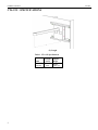
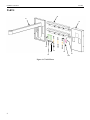
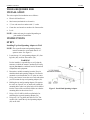
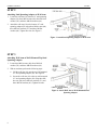
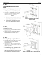
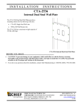
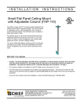
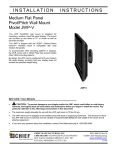
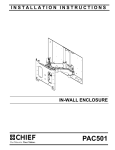
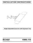
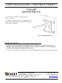
INSTALLATION
INSTRUCTIONS
CTA-225
Dual Stud Wall Arm
The CTA-225 has a maximum weight capacity of
300 lbs. (136.1 kg).
The wall arm on the CTA-225 is 25.2” in length from the
wall mount, providing ample room to install and position a
small or large TV/Monitor.
CTA-225 Dual Stud Wall Arm
BEFORE YOU BEGIN
•
CAUTION: To prevent damage to your equipment, which could affect or void the Factory warranty,
thoroughly study all instructions and illustrations before you begin to install the CTA-225. Pay particular
attention to the Warnings and Cautions in this document.
•
If you have any questions about this installation, contact Chief Manufacturing at 1-800-582-6480 or 952-582-6480.
CHIEF MANUFACTURING INC.
1-800-582-6480 952-894-6280 FAX 952-894-6918
8401 EAGLE CREEK PARKWAY, STE. 700
SAVAGE, MINNESOTA 55378 USA
8809-000025 (Rev. A)
2004 Chief Manufacturing
www.chiefmfg.com
11/04
Installation Instructions
CTA-225
CTA-225 – SPECIFICATIONS
(L) Length
Table 1. CTA-225 Specifications
Model
CTA-225
2
L-Length
(fixed)
25.2”
Max
Support
Weight
300 lbs
(136.1 kg)
Installation Instructions
CTA-225
IMPORTANT WARNINGS and CAUTIONS!
WARNING
A WARNING alerts you to the possibility of serious injury or death if you do not follow the
instructions.
CAUTION
A CAUTION alerts you to the possibility of damage or destruction of equipment if you do not follow
the corresponding instructions.
WARNING
Improper installation can result in serious personal injury! Make sure that the mounting surface
can support a redundant weight factor five times the total weight of the equipment: if not,
reinforce the mounting surface structural members before installing the mount.
WARNING
Be aware of the potential for personal injury or damage to the equipment if it is not adequately
mounted.
WARNING
The installer is responsible for verifying that the mounting surface to which the CTA-111 is
anchored will safely support the combined load of all attached components or other equipment.
WARNING
The combined weight of the TV/monitor and all attached components and equipment placed on a
Chief Wall Arm must not exceed 300 lbs. (136.1 kg), the maximum support weight of the CTA-225.
WARNING
Watch for pinch points. Do not put your fingers between movable parts.
CAUTION
Check the unit for shipping damage before you begin the installation.
CONTENTS
CTA-225 – SPECIFICATIONS........................................2
CONTENTS......................................................................3
INSPECT THE UNIT BEFORE INSTALLING ..............3
PARTS ..............................................................................4
TOOLS REQUIRED FOR INSTALLATION ..................5
INSTRUCTIONS..............................................................5
Installing Top Stud Spanning Adapter to Wall .............5
Attaching Stud Spanning Adapter to Wall Arm............6
Attaching Wall Arm to Wall-Mounted Top Stud
Spanning Adapter ..........................................................6
Attaching Bottom Stud Spanning Adapter to Wall .......7
Attaching Front Cover...................................................7
Connecting NPT Pipe or Nipple to Wall Arm...............7
INSPECT THE UNIT BEFORE
INSTALLING
Unpack the carton. Carefully inspect the parts for
shipping damage. Verify contents listed in Table 2.
If you are missing any of the listed parts, contact
Customer Service at: 1-800/582-6480.300.
Table 2. Shipping Contents
ITEM
10
20
30
40
50
60
70
80
90
100
110
DESCRIPTION
Wall Arm
16” Spanning adapter
Front Cover
5/16 X 2.5” Lag Bolt
5/16 Flat Washer
M8 Flat Washer
M8 Lock Washer
M8 Hex Nut
M4 X 8mm Phillips Head Cap Screw
M6 X 6mm Set Screw
M3 Allen Key (not shown)
QTY
1
2
1
4
4
6
6
6
4
1
1
3
Installation Instructions
CTA-225
PARTS
20
10
30
40
70
80
50
Figure 1. CTA-225 Parts
4
60
90
100
Installation Instructions
CTA-225
TOOLS REQUIRED FOR
INSTALLATION
The tools required for installation are as follows:
•
Electric drill and bit set
•
Stud sensor (mechanical or electronic)
•
½” box-end wrench or ratchet with ½” socket
•
13mm box-end wrench or ratchet with 13mm socket
•
Level
NOTE: Other tools may be required depending on
your method of installation.
INSTRUCTIONS
STEP 1
Installing Top Stud Spanning Adapter to Wall
NOTE: The top and bottom stud-spanning adapters
must be mounted to wood studs that are 16”
apart on center. See Figure 2.
1. Locate the top 16” stud-spanning adapter (20), four
lag bolts (40), and four flat washers (50).
WARNING
It is the installer’s responsibility to verify that the
structure to which the mount is anchored will safely
support five times the combined load of all attached
components and equipment.
16”
2. Determine a suitable mounting location. Keep in
mind that both stud-spanning adapters (20) must be
mounted to wood studs that are 16” apart on center.
3. Using a stud sensor, locate the two wood studs where
you will mount the top stud-spanning adapter (20).
4. Holding the top stud-spanning adapter (20) against
the wall, use a pencil, awl, or small nail to mark the
mounting holes where two pilot holes will be drilled
into the center of the wood studs. Make sure that the
mounting holes in the unit are level.
Figure 2. Install Stud Spanning Adapter
5. Using a 15/64” drill bit, drill two pilot holes for
anchoring the top stud-spanning adapter (20).
6. Using two 5/16” lag bolts (40) and two 5/16” flat
washers (50), install the top stud-spanning adapter
(20) on the wall.
5
Installation Instructions
CTA-225
STEP 2
Attaching Stud Spanning Adapter to Wall Arm
1. Locate the wall arm (10), bottom 16” stud-spanning
adapter (20), three M8 hex nuts (80), three M8 lock
washers (70), and three M8 flat washers (60).
2. Attach the wall arm (10) to the bottom 16” studspanning adapter (20) using three M8 hex nuts (80),
three M8 lock washers (70), and three M8 flat
washers (60). Tighten hex nuts. See Figure 3.
Figure 3. Attach Stud Spanning Adapter to Wall Arm
STEP 3
Attaching Wall Arm to Wall-Mounted Top Stud
Spanning Adapter
1. Locate three M8 hex nuts (80), three M8 lock
washers (70), and three M8 flat washers (60).
2. With an assistant, perform the following steps:
a. Lift the wall arm (10) onto the top wall-mounted
16” stud-spanning adapter (20). See Figure 4.
b. Secure the wall arm (10) to the top wall-mounted
16” stud-spanning adapter (20) using three M8
hex nuts (80), three M8 lock washers (70), and
three M8 flat washers (60). Tighten hex nuts.
Figure 4. Attach Wall Arm to Wall-Mounted Stud
Spanning Adapter
6
Installation Instructions
CTA-225
STEP 4
Attaching Bottom Stud Spanning Adapter
to Wall
1. Locate two lag bolts (40) and two flat washers (50).
2. Using a 15/64” drill bit, drill two pilot holes for
anchoring the bottom stud-spanning adapter (20).
3. Using two 5/16” lag bolts (40) and two 5/16” flat
washers (50), secure the bottom stud-spanning
adapter (20) on the wall. See Figure 5.
NOTES
•
•
The front cover may be partially removed and
reinstalled to conceal power/audio/video cables
after the TV/Mount is installed.
You may remove one or both knockouts on
cover to assist routing to wall through cover.
Figure 5. Attach Bottom Stud Spanning
Adapter to Wall
STEP 5
Attaching Front Cover
1. Locate front cover (30) and four M4 8mm Phillips
head cap screws (90).
2. Install the front cover (30) using four M4 8mm
Phillips head cap screws (90). See Figure 6.
Figure 6. Attach Front Cover
STEP 6
Connecting NPT Pipe or Nipple to Wall Arm
1. Locate M6 x 6mm set screw (100) and 1-1/2” NPT
pipe or nipple (supplied with TV Mount or
purchased separately).
2. Connect the 1-1/2” NPT pipe or nipple (supplied
with TV Mount or purchased separately) to the wall
arm (10). See Figure 7.
3. Using the M3 Allen key (110, supplied), install the
M6 x 6mm set screw (100). Tighten the set screw.
WARNING
Make sure to tighten the M6 x 6mm set screw (100)
to prevent equipment damage or personal injury.
Figure 7. Connect NPT Pipe or Nipple to Wall Arm
7