1
User Manual
125* High Speed Mode Wireless
Secure Remote Router
WZR-RS-G54
Rev B
www.buffalotech.com
Table of Contents
Introduction . . . . . . . . . . . . . . . . . . . . . . . . . . . 05
Installation / Setup . . . . . . . . . . . . . . . . . . . . . . 11
Antenna Installation. . . . . . . . . . . . . . . . . . . . . . 13
Standard Settings . . . . . . . . . . . . . . . . . . . . . . . 14
AOSS Setup . . . . . . . . . . . . . . . . . . . . . . . . . . . 23
Advanced Setup . . . . . . . . . . . . . . . . . . . . . . . . 26
LAN Settings . . . . . . . . . . . . . . . . . . . . . . . . 26
Wireless Settings . . . . . . . . . . . . . . . . . . 26
Wireless LAN Security . . . . . . . . . . . . . . 28
LAN Port . . . . . . . . . . . . . . . . . . . . . . . . 32
DHCP Server . . . . . . . . . . . . . . . . . . . . . 33
Wireless MAC Filtering . . . . . . . . . . . . . 36
Wireless Bridge (WDS) . . . . . . . . . . . . . 38
WAN Settings . . . . . . . . . . . . . . . . . . . . . . . 40
WAN Port . . . . . . . . . . . . . . . . . . . . . . . . 40
WAN Network . . . . . . . . . . . . . . . . . . . . . 43
2
Table of Contents
PPTP Client Setup . . . . . . . . . . . . . . . . . . . . 44
PPTP Server Setup . . . . . . . . . . . . . . . . 46
Dynamic DNS Setup. . . . . . . . . . . . . . . . 47
Network Settings. . . . . . . . . . . . . . . . . . . . . 49
Routing Setup . . . . . . . . . . . . . . . . . . . . 49
Address Translation . . . . . . . . . . . . . . . . 51
Packet Filter . . . . . . . . . . . . . . . . . . . . . . 54
Intrusion Detector . . . . . . . . . . . . . . . . . 59
UPnP . . . . . . . . . . . . . . . . . . . . . . . . . . . 61
Management . . . . . . . . . . . . . . . . . . . . . . . . 62
System Information . . . . . . . . . . . . . . . . 62
Change Password . . . . . . . . . . . . . . . . . 63
Time Setup . . . . . . . . . . . . . . . . . . . . . . 64
Traffic Information . . . . . . . . . . . . . . . . . 65
Client Monitor . . . . . . . . . . . . . . . . . . . . 66
Ping Tool . . . . . . . . . . . . . . . . . . . . . . . . 67
Log Information . . . . . . . . . . . . . . . . . . . 68
3
Table of Contents
Syslog Transfer . . . . . . . . . . . . . . . . . . . 69
Save/Restore Settings . . . . . . . . . . . . . . 70
Reboot/Reload Settings . . . . . . . . . . . . . 71
Firmware Updates . . . . . . . . . . . . . . . . . 72
AOSS . . . . . . . . . . . . . . . . . . . . . . . . . . . 73
Network Service List . . . . . . . . . . . . . . . . . . . . . . . . . 75
File & Printer Sharing / Audio/Video Playback . . 77
Remote Control . . . . . . . . . . . . . . . . . . . . . . . . . 78
Specifications . . . . . . . . . . . . . . . . . . . . . . . . . 81
Troubleshooting . . . . . . . . . . . . . . . . . . . . . . . . 85
Glossary
. . . . . . . . . . . . . . . . . . . . . . . . . . . .94
FCC/CE Information . . . . . . . . . . . . . . . . . . . . . . . . 100
Warranty Information. . . . . . . . . . . . . . . . . . . . . 105
Contact Information . . . . . . . . . . . . . . . . . . . . . 106
4
Introduction
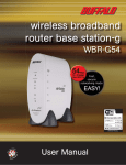
AirStation 125 High Speed Mode Wireless Cable/DSL Router (WZR-RS-G54)
This manual introduces you to the AirStation Cable/DSL Router, and will help you connect to your
network quickly.
The WZR-RS-G54 router, is a wireless 4-port router network device that complies with the 2.4GHz
IEEE 802.11g standard specification on wireless LANs. It also supports 125 High Speed Mode
technology. The WZR-RS-G54 supports enhanced built-in NAT/SPI firewall functions and is used
as a multi-functional router/link between wired and wireless LAN computers. Additionally, the WZRRS-G54 includes a secure PPTP Server designed to serve remote clients with access to the LAN
and special features via an easy to use Network Service List.
Summary of the AirStation WZR-RS-G54 features:
• Wi-Fi™ (Wireless Fidelity) certified by the Wi-Fi Alliance as an 802.11b/g device. The AirStation
will communicate with other IEEE 802.11b/g/Wi-Fi compliant wireless LAN products.
• Supports 125* High Speed Mode
• Auto-Channel Selection
• Support for Wi-Fi Protected Access™ (WPA), 802.1x, TKIP, AES, and WEP.
• PPTP Endpoint Client
• PPTP Server
• DHCP client/server function.
• Auto roaming, supports seamless roaming over multiple channels.
• VPN pass-through, for secure communications.
5
Introduction
• Packet Filtering for eliminating unwanted communications.
• SOHO/SMB routing and firewall functions provide a safer private networking environment, including support for MS NetMeeting and MSN-Messenger.
• Additional SPI Firewall Functions - DMZ, intrusion detection and notification
• Syslog transmits some or all system activities to a central Syslog server.
• Extended range, with optional add-on antennas or WDS (Wireless Distribution System).
• Auto Media Dependent Interface/Crossover (MDI/X) port, allows connection by standard and
crossover CAT5 cables.
• Supports Universal Plug and Play (UPnP).
• Buffalo’s AOSS System for easy, secure wireless client configuration.
• Enhanced security features:
- SPI Firewall and DMZ zone functions to prevent unknown intruders.
- Intrusion Detector Firewall (NAT) with a pop-up or email alert warning unwanted attacks.
- Dynamic packet filtering.
- WPA, 802.1x, TKIP, AES, and WEP.
- VPN (IPSec, PPTP and L2TP) pass-through
- Packet monitoring and filtering by MAC address, IP address and port.
- PPPoE support
- WDS support
6
Introduction
• Buffalo’s easy web interface configuration
• Broadband router static and dynamic routing methods between WAN and LAN based on updated
routing tables. An economical way to bridge multiple networks.
• Optional external antennas for boosting range and signal quality.
• Buffalo’s AOSS System for easy, secure wireless client configuration.
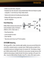
Home Networking 1
Buffalo AirStation wireless access points enable
sharing broadband by simply connecting the
AirStation to a DSL or Cable modem to:
• Share files and printers
• Access and share the Internet
• Share media files
• Take remote control of any of your PC’s from anywhere.
SOHO/SMB Networking
With high-speed DSL or Cable connections readily available, many users can work effectively from
a home office, connected securely to a corporate network. Buffalo’s solutions are ideal for home
networks that require secure, high-speed access to the corporate LAN. Tools that play an integral
part in Buffalo’s solutions include VPN connectivity for secure access to corporate resources, which
enable the remote employee to handle information from clients or coworkers as if they were in the
office. Connect the Buffalo AirStation Broadband router AP to a Cable or DSL modem in order to:
7
Introduction
•Share broadband access
•Share files and printers
•Bridge between multiple networks and multiple computer platforms
•Provide easy and secure access to home or company networks from remote locations
System Requirements
• Broadband (High-Speed) Internet connection or existing Local area connection
• Any Wi-Fi (wireless) compatible computer with a Web Browser Internet Explorer or Netscape 4.5
or later. (Safari 1.0 is supported with Macintosh OS X.2)
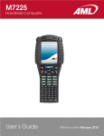
AirStation WZR-RS-G54 Package Contents
The AirStation WZR-RS-G54 package consists of the following items.
1. WZR-RS-G54 Base Station
2. AC adapter and power cable
3. CAT5 LAN cable
4. Utility CD with Manual
5. Quick Setup Guides
6. Warranty Statement
8
Introduction
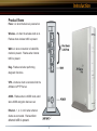
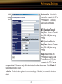
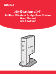
Product Views
Power - Lit when the device is powered on.
Wireless - Lit when the wireless radio is on.
Flashes when wireless traffic is present.
WAN - Lit when connection to Cable/DSL
modem is present. Flashes when internet
traffic is present.
Diag - Flashes red when performing
diagnostic functions.
VPN - Lit when a client is connected into the
AirStation’s PPTP Server.
AOSS - Flashes when in AOSS mode, solid
when AOSS encryption has been set.
Ethernet - 1, 2, 3, or 4 lit when ethernet
clients are connected. Flashes when
ethernet traffic is present.
9
Introduction
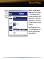
About the AirStation CD
The AirStation does not require any software to be installed on your computer for configuration. The
AirStation CD contains product documentation, TightVNC Remote Control Software, and Buffalo’s
Client Manager which provides AOSS functionality for any Buffalo client card or any Intel Centrino
notebook.
It is the policy of Buffalo Technology to improve products as new technology, components, software
and firmware become available.
Please consult the AirStation wireless website (http://www.buffalotech.com/wireless) to download
and install the latest firmware for your product.
Follow these simple steps to connect the AirStation to your Broadband Internet connection allowing
you to combine and share wired and wireless computers and printers with the high-speed internet
connection.
10
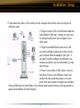
Installation / Setup
1. Power down the Cable or DSL modem and the computer which will be used to configure the
AirStation router.
2. Plug the Cable or DSL’s LAN Ethernet cable into
the AirStation’s WAN port. Initially, you may need
to unplug this cable from your computer, hub or
other router.
3. Plug the provided Ethernet cable into a LAN
port on the AirStation and plug the other end into
your computer Ethernet adapter’s (NIC) port. If
you plan to initially configure the AirStation via a
wireless connection, (not recommended), you may
skip this step.
4. Power on your cable or DSL modem, wait one
full minute, Power on the AirStation router, wait
another full minute and then power on the computer which will be used to configure the AirStation.
If the red DIAG light on the AirStation is lit or flashing after several minutes of being powered on,
please consult Buffalo Technical Support.
11
Installation / Setup
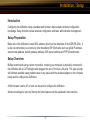
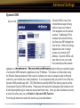
Introduction
Configuring the AirStation using a standard web browser requires basic wireless configuration
knowledge. Setup includes manual wireless configuration and basic administrative management.
Setup Preparation
Make note of the AirStation’s wired MAC address (found on the underside of the WZR-RS-G54). It
is also recommended you record any other broadband ISP information such as global IP address,
subnet mask address, default gateway address, DNS server address and PPPoE parameters.
Setup Overview
Buffalo recommends using a wired connection, meaning your computer is physically connected to
the AirStation with a CAT5 straight cable plugged into one of the four LAN ports This type of setup
will eliminate possible setup problems due to any issues with the wireless adapter on the computer
being used to configure the AirStation.
A Web browser version 4.5 or later can be used to configure the AirStation.
Advanced settings for security, filtering and other features will be explained in later sections.
12
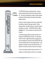
Antenna Installation
The WZR-RS-G54 has two internal antennas. One has a
vertical orientation while the other has a horizontal orientation. This setup is ideal because it allows for proper antenna
polarization with both desktop and notebook style wireless
adapter antennas.
However, it may be necessary to increase your range further
by installing an external, higher-gain antenna. External
antennas come in all shapes and sizes. Antennas also come
with different connectors. The WZR-RS-G54 has an ‘MC
Connector’ on it. Thus, the antenna must also have an MC
connector.
To install the antenna, slide the antenna connector door on
the back of the WZR-RS-G54 to the right. This will expose
the MC Connector. Attaching the antenna is simple, just insert the antenna’s MC Connector into the WZR-RS-G54’s MC
Connector and firmly push it in until it snaps into place. Once
snapped, the antenna’s connector will swivel with ease. It is
important not to push the antenna connector in at an angle.
To remove the antenna, pull the antenna connector out. It is
important not to pull the antenna connector out at an angle.
13
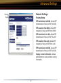
Standard Settings
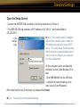
Open the Setup Screen
• Connect the WZR-RS-G54 according to the wiring instructions in Section 2.
• The WZR-RS-G54 has a default LAN IP address of 192.168.12.1 and Subnet Mask of
255.255.255.0.
■ Note: The computer used to configure
the AirStation should be set to obtain an
IP address automatically using a DHCP
server. The Quick Setup Guide enclosed
with the product contains detailed instructions on how to configure your computer
for initial configuration.
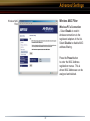
Initial
Settings
Login
On the computer used to configure the
AirStation, launch a Web Browser 4.5 or
later.
- Enter 192.168.12.1 into the URL field.
- A window will open prompting you to
enter a User ID and Password.
Enter “root” as the User ID and leave the password field blank.
■ Note: These are the factory default settings
14
Standard Settings
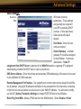
Enter ISP information
Initial
Settings
Screen
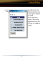
• Click the appropriate button to select the type
of broadband access. (Users more experienced
in networking may choose to select the Advanced button and skip to Section 4.)
• For supplementary tools, use the tabs along
the top of the screen.
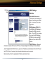
DSL Button
Initial DSL
button
Screen
Select the appropriate connection method.
Automatic IP Assignment by ISP
- The DHCP server of the ISP assigns an IP address automatically.
15
Standard Settings
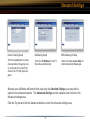
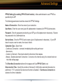
Manual DSL
IP Settings
Screen
Enter IP Address Manually
DSL PPPoE
Settings
Screen
PPPoE Connection
- Enter the IP Address given by the ISP.
- Use ‘Enter IP Address Manually’ if the ISP
requires use of a static IP address.
- Enter the PPPoE information provided by the
ISP.
16
Standard Settings
CATV (Cable) Button
Initial CATV
Settings
Screen
Select the appropriate connection method.
Automatic IP Assignment by ISP
- Select ‘Automatic IP Assignment by ISP’ if
your ISP’s DHCP server assigns an IP address
automatically.
Manual IP
Address
Settings
Enter IP Address Manually
- Select ‘Enter IP Address Manually’ if the ISP
requires use of a static IP address.
17
Standard Settings
Auto IP/
Manual DNS
Settings
The IP Address is Acquired
Automatically but DNS Server Address
is Entered Manually
- Select ‘IP address is acquired automatically
but DNS server address is entered manually’ if
the ISP’s DHCP server supplies an IP address
but not DNS server addresses.
Line
Test Tab
Line Test
Tests the connection to the Internet.
18
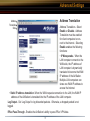
Standard Settings
Security Tab
Security
The Security Tab offers three Simple Security
Settings. Follow the instructions in each screen
to enter Encryption Keys, MAC Address Filtering and the degree of firewall security for the
AirStation.
19
Standard Settings
Encryption Setup.
Simple MAC Address Filter.
Simple Security Setup.
- Select the desired encryption
scheme from the choices. After
it has been selected, press the
‘Next’ button. You will then be
prompted to enter the appropriate
key(s) for that method of encryption.
- Select ‘Enable’ to use MAC filtering. See ‘Page 36’ for more information on MAC Address Filtering.
- See ‘Page 55’ for more information
on Intrusion Detector.
20
Standard Settings
Application
Tab
Applications
The Application Tab offers setup for special applications such as games, MS NetMeeting and
MSN Messenger. Then follow the on-screen
menus to configure the AirStation for the application.
21
Standard Settings
Internet Gaming Setup
NetMeeting Setup
MSN Messenger Setup
-Enter the ports(refer to Game
documentation) the game runs
on, and enter the Local IP Address of the PC that plays the
game.
-Enter the IP Address of the PC
that will use Netmeeting.
-Refer to the on-screen help for
information about Messenger.
Although your AirStation will function fine using only the Standard Settings, you may wish to
explore more advanced options. The Advanced Settings section explains each function in the
Advanced settings area.
Click the Top tab and click the Advanced button to enter the Advanced settings area.
22
AOSS
AOSS (AirStation One-Touch Secure System) is a simple, one-touch setup for connecting wireless
clients to an access point while setting up the most secure possible connection. Users no longer
need to worry about choosing the proper security protocols, IP addresses, or SSID's. The
intelligence of AOSS determines the most optimal connection and configures itself in seconds.
■ NOTE: AOSS automatically creates a secure connection between your AOSS Access Point and
client. You must have an AOSS enabled wireless client device to use the AOSS features of your
AOSS Access Point/Router. Intel Centrino supports AOSS by installing Buffalo's Client Manager
software.
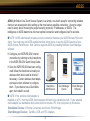
◗ Configure your WZR-RS-G54’ internet
connection by referring to the instructions
in the WZR-RS-G54’ Quick Setup Guide.
◗ Once the WZR-RS-G54 has been configured, follow the directions to install your
wireless client device and its drivers if
necessary. Certain wireless client adapters require client software to configure
Standalone
Client Manager
Client Manager
them. If your device has a Client ManDevice
Software
AOSS Device
ager, then install it as well.
■ NOTE: If the wireless client adapter is
installed on a PC, then the AOSS client manager will need to be installed as well. If your wireless
client adapter is a standalone device that does not require a PC, then just power up the device.
Standalone Devices: Ethernet Converters and Access Point Bridges
Client Manager Devices: CardBus, USB, and PCI Adapters.
23
AOSS
◗ Now that the WZR-RS-G54 and wireless client adapter
are installed, you can use AOSS to configure them.
◗ To begin the configuration, press the AOSS button on
the side of the WZR-RS-G54 for 3-5 seconds. The orange
AOSS light will begin to flash rapidly when the AOSS mode
has been enabled. You can stop pressing the button at this
point.
■ NOTE: AOSS mode will stay active for a period of two
minutes. This is the time-slot required to initiate AOSS on
the wireless client adapter.
◗ Refer to your wireless client adapter's AOSS supplement
to initiate the wireless client adapter's AOSS mode.
◗ Once the client adapter has finished communicating
with the AOSS router, the orange light will stop flashing
and become solid. This indicates that the AOSS process
has completed and the devices are now using AOSS. It
typically takes 15-60 seconds for the entire AOSS process
to complete. Please refer to your wireless client adapter's
supplement for the remainder of the setup.
24
AOSS
Additional AOSS Information:
◗ Only one AOSS wireless client adapter can be configured to the AOSS router at a time. Thus,
the button will need to be repressed for each additional AOSS wireless client adapter that will be
connected.
◗ It is not necessary to AOSS client devices that have already been configured via AOSS, unless
significant changes have been made to the wireless network.
◗ Do not attempt to configure two separate AOSS networks at the same time, as it may cause
undesired configurations.
◗ If an undesired client has connected via AOSS, it can be disconnected from within the WZR-RSG54’ advanced configuration menus.
25
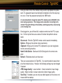
Advanced Settings
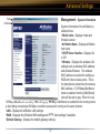
LAN Settings
Set up LAN connections.
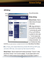
Wireless
Settings
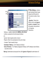
Wireless Settings
Wireless Function - Enable or
disable wireless LAN computer
communication.
SSID - Allows administrator to
alter the SSID of the AirStation.
To communicate with a specific
AP only, the AP’s SSID must
be entered in the client computer. The client computer looks
for the specific AP (or SSID) for
wireless communication. Use
up to 32 alphanumeric characters for the SSID (case sensitive). By default the SSID is the LAN Mac address of the AirStation.
■ Note: Roaming - When multiple AirStations have an identical SSID, WEP key (if WEP is used),
(and channel in WDS mode) , client computers may Roam between the AirStations.
Wireless Channel - Select the channel used for wireless communication. There are 11 overlapping channels. Channels 1, 6 and 11 are non-overlapping. The ‘Auto-Channel’ option is recommended, as it constantly assesses the best available channel for the AirStation to operate on.
26
Advanced Settings
If there are multiple APs in close proximity using the same channel, there may be interference. In this
case, change to a non-overlapping channel.
Privacy Separator - Enable or disable communication between wireless clients. If you choose to use this
feature, every wireless client that is associated to the AirStation will not be able to communicate with any
other wireless clients.
■ Note: If this function is used, wired clients can still communicate with wireless clients.
BSS (Basic Service Set) Basic Rate Set - The transmission data rates offered by the AirStation. It is
recommended to use the ‘Default’ selection to accomidate 802.11 and 802.11b rate sets. It is NOT recommended to use the ‘All’ selection, as some devices may not understand all of the rate sets offered by the
AirStation.
Frame Bursting - This function increases 802.11g communication throughput by transferring packets more
efficiently. The following conditions affect this function:
• The wireless LAN client adapter must support Frame Bursting (and it must be enabled). If the wireless
LAN client adapter does not support Frame Bursting, or Frame Bursting is not enabled, then it will
operate at non-Frame Bursting speeds.
125 High Speed Mode - This function further increases 802.11g communication. Rate sets up to 125
Mbps are offered to clients.The following conditions affect this function:
• The wireless LAN client adapter must support 125 High Speed Mode (and it must be enabled). If the
wireless LAN client adapter does not support 125 High Speed Mode, or it is not enabled, then it will
operate at regular 802.11g speeds.
It is recommended to leave 125 High Speed Mode enabled as it can only help throughput, not hurt it.
27
Advanced Settings
802.11g Protection - This enables protection mechanisms for when 802.11b clients join the network. It enables CTS (Clear-to-Send)
DTIM Period - An access point transmits beacon signals to nearby clients at a preset interval. This
parameter sets the beacon transmission interval time (1-255 seconds). Selection of a larger number may conserve energy for the client computer (when client power management is enabled), but
may delay wireless communication. The default value of 1 is recommended.
Wireless Output Power - Configure output power of the AirStation. Decrease wireless output
power to shrink the wireless communication range. The default setting of 100% is recommended
unless decreased range is desired
Wireless LAN Security
Wireless
Security
Settings
Broadcast SSID - Enable or Disable the SSID (SSID) from being
broadcasted. If denied, the AirStation
will not be found unless the specific
AirStation’s SSID is entered in the
client computer manually.
Data Encryption - Disable to have no
encryption of the wireless data. This
will make accessing the AirStation
and the network very easy. It is im28
Advanced Settings
portant to note, that without encryption it is easy for strangers to connect to your network, especially
if the AirStation is broadcasting its SSID.
Select the type of data encryption:
• Disabled - Disable data encryption.
- WEP - Uses WEP encryption. Encryption key should be entered.
- TKIP - Uses TKIP (Temporal Key Integrity Protocol) for data encryption.
The encryption key is renewed every “Re-key interval” when “TKIP” is selected.
WEP - When the WEP (Wired Equivalent Protection) encryption standard is implemented into a
wireless network, a WEP key is used between the client and access point to successfully encrypt,
transmit and decrypt data. For this reason, the same WEP key must be used for communication
between the client and the AirStation.
An access point and client may both carry multiple WEP keys. It is necessary for not only the WEP
keys to match, but also the WEP key’s order. If a wireless client cannot support multiple WEP keys,
the AirStations must be configured to transmit key number 1 for a connection to take place.
Examples of WEP key:
64-bit ASCII: 5 digits of alphanumeric characters, “ab34Y”
128-bit ASCII: 13 digits of alphanumeric characters, “123456abcdef7”
■ Note: ASCII WEP keys are case sensitive.
64-bit HEX: 10 digits, using characters 0-9 and a-f, “00234ABCDE”
29
Advanced Settings
128-bit HEX: 26 digits, using characters 0-9 and a-f, “20123456789abcdeabcdeabcde”
TKIP - TKIP (Temporal Key Integrity Protocol) is a WEP expanded encryption technique. TKIP has
greatly improved WEP’s weaknesses by rotating secret keys between every packet. TKIP uses
WPA-PSK (pre-Shared Key).
Characteristics:
- The Initialization Vector is expanded from 24-bits to 48-bits.
- The Initialization Vector is randomized.
- Uses a different RC4 key for every packet.
AES - AES further improves TKIP by using AES (Advanced Encryption Standard) encryption
method. Due to its hardware co-processor, AES uses the toughest encryption without sacrificing
throughput like WEP and TKIP.
TKIP & AES require an 8 to 63 character passphrase in ASCII or 64 digits hexadecimal key.
Example 1: [ airstation -WPA-PSK ]
Example 2: [0123456789abcdef0123456789abcdef0123456789abcdef0123456789abcdef]
WPA Group Rekey Interval - When TKIP is selected, the encryption key is renewed at this interval. This interval is in seconds; the range of acceptable values is 0-3600.
If 0 is entered, the key is never renewed.
■ Note: The lower the rekey interval, the more often a rekey occurs. Setting a low rekey interval
may affect performance negatively.
30
Advanced Settings
IEEE802.1x/EAP authentication (WPA) - Configure Authentication and WPA Settings.
Disable - Do not use any RADIUS Server based authentication.
Enable - Authorized clients access this AirStation via a RADIUS Server.
Use 802.1x/EAP to authorize every wireless client who wants to access the AirStation by using
802.1x/EAP and a RADIUS Server. The RADIUS server provides login information for every user
establishing a more secure system than TKIP or other fixed encryption key methods. This also
reduces the amount of necessary key maintenance.
A RADIUS server is necessary for IEEE802.1x/EAP authentication. Enter [RADIUS Server], {RADIUS Port] and [RADIUS Key] information.
RADIUS authentication
RADIUS Server - Enter RADIUS server IP address.
RADIUS Port - Enter port number for authentication.
RADIUS Key - Encryption key between RADIUS Sever and the AirStation. Enter the same key as
registered in the server. Use a 1 to 256 character alphanumeric code.
31
Advanced Settings
LAN Port
Settings
LAN Port
Set the LAN side Ethernet
settings.
LAN Side IP Address - Allows
administrator to specify a static
IP and Subnet Mask for the
LAN side of the AirStation.
■ Note: If the AirStation’s IP
address is changed, the configuring computer’s IP must be
changed to the same range to
continue configuration. If the
LAN IP is changed, restart the
AirStation. (Section 4.4.10). If
the IP address is changed, then the DHCP scope must be changed to match.
DHCP Server Function - Allows administrator to enable/disable the DHCP server function for the
AirStation LAN side. Select Use to enable and Do not use to disable the function. Once Use is
selected, the assigned IP address range can be specified. Enter the starting LAN IP address and
total number of computers the DHCP server can accomidate.
■ Note: If there is another DHCP server on the network, one either must be disabled or the IP
range must be changed to avoid conflicts derived from overlapping DHCP scopes.
32
Advanced Settings
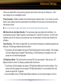
DHCP Server
DHCP Server
Settings
Allows a more advanced configuration of the DHCP server
functions.
DHCP Server Function - Allows administrator to enable/
disable the DHCP server function for the AirStation LAN side.
Select Use to enable or Do not
use to disable this function.
If the DHCP service is enabled,
wireless and wired clients
may receive IP addresses and
other network information from
the AirStation. If the DHCP
server is turned off, all client PC’s must have unique, static IP addresses and valid network settings
manually entered. Check with your LAN administrator for static IP information.
Assigned IP address (Range Assignment) - Sets the beginning address and range of addresses
to be assigned by the AirStation’s DHCP server function. Select up to 253 consecutive addresses
(nodes). The IPs to be excluded from the range specification should be entered in the specified
field.
33
Advanced Settings
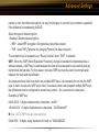
Lease duration - Specifies the time in hours (1-999) an assigned IP address is valid. If the client
computer does not request a renewal of IP address before the lease period expires, the AirStation
can issue the IP to another client computer.
Default Gateway - Allows administrator to use the Default Gateway address (the AirStation’s IP
address), assign a specific Gateway address, or block clients from Gateway notification.
DNS server - Allows administrator to use the default DNS address (the AirStation’s IP address),
assign specific DNS addresses, or block clients from DNS address notification.
WINS server - Allows administrator to use a WINS address. Select auto assignment of the IP address, enter a specific WINS IP address, or block clients from the WINS address notification.
Domain name - Allows administrator to use an assigned domain name, assign a specific domain
name, or block clients from domain name notification. Domain names will be sent to LAN computers when an IP address is assigned. Enter a maximum of 64 alphanumeric characters.
34
Advanced Settings
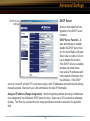
Manual IP
and MAC
Address
Assignment
Settings
Manual IP and MAC Address
Assignment - Allows administrator to add additional leased IP
addresses tied to a specific MAC
address. When a specific MAC
address connects to the AP, the
IP address specified will be given
to that client.
Display/Delete lease information - List of IP addresses, MAC
addresses, lease periods and
status is displayed.
35
Advanced Settings
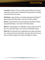
Wireless MAC
Filter
Wireless MAC Filter
Wireless PC’s Connection
- Select Enable to restrict
wireless connections to the
registered adapters in the list.
Select Disable to disable MAC
address filtering.
Press the Preset button
to enter the MAC Address
registration menus. This is
where MAC Addresses can be
assigned and deleted.
36
Advanced Settings
Registration for MAC Addresses - MAC access
restriction set up in LAN. Input
the MAC addresses that are
allowed to communicate with
the AirStation.
Register for
Allowable PC’s
MAC Address
MAC address list - Displays a
table list of all MAC addresses
allowed to communicate with
the AirStation.
37
Advanced Settings
Wireless Bridge (WDS)
Wireless
Bridge (WDS)
Settings
The Wireless Distribution
System supports peer-to-peer
AP communication.
Wireless Bridge (WDS) Function - Select Enable to allow
Bridge (WDS) mode between
AirStations or Disable to
block communication between
AirStations.
Wireless Bridge (WDS) dedicated mode - Select Enable to
restrict wireless computer communication with the AirStation.
In dedicated mode wireless
clients CANNOT connect to
WDS AirStations.
■ Note: All AirStations must support WDS and be on the same channel. Do not use ‘Auto-Channel’
when using WDS. For roaming support, use the same SSID on all devices.
Add a WDS Partner: Allows administrator to input the wireless MAC address of AirStations for
Bridge (WDS) communication. The wireless MAC address is found in the Management section =>
System Information, labeled Wireless MAC Address.
38
Advanced Settings
To enable WDS, set the Wireless Bridge (WDS) function to
Enable.
Wireless
Bridge (WDS)
Settings
Enter the Wireless MAC
address of the AirStation to
communicate with in the form
of two characters separated by
a colon and click Add.
MAC Address Ex:
00:00:00:00:00:00
Up to six AirStation MAC addresses may be registered.
Click Apply under Wireless
Bridge (WDS) settings when
the wireless Mac addresses
AirStation are entered.
Repeat this process on every other AirStation used in Bridge (WDS) mode.
39
Advanced Settings
WAN port
Setup
WAN Settings
WAN Port
Wired WAN Performance
- Select port speed and type of
duplex connecting to the WAN
port. If unknown, select Auto
negotiation.
MAC Address of WAN - Set
the AirStation MAC address to
be used for WAN communication. Some ISP’s may require
you to set the MAC Address
of WAN to be the same MAC
address of your cable or DSL
modem.
WAN IP Address - Allows administrator to select DHCP server, PPPoE, or manual setting for the WAN port of the AirStation.
Auto IP assignment from DHCP server - acquire the IP address automatically from the DHCP server.
Use PPPoE client - If selected, the information listed below must be entered.
Manual setting - Enter the appropriate IP address and subnet mask.
40
Advanced Settings
PPPoE Setting (for enabling PPPoE Client function) - Allows administrator to use PPPoE as
specified by the ISP.
The following parameters should be entered for PPPoE Settings:
Name of Connection - Enter the name of your connection.
User Name - Enter the user name (up to 64 alphanumeric characters) for PPPoE authorization.
Password - Enter the password provided by your ISP (up to 64 alphanumeric characters). Reenter
the password in the Confirmation box.
Service Name - Enter the PPPoE service name (up to 64 alphanumeric characters). If your ISP
doesn’t require a service name, then leave it blank.
Connection Type - Select from:
- Continuous Connection - connects immediately after setting and never
disconnects.
- Connect on Demand - Reconnects when the disconnect time elapses.
- Manual - Disables Automatic Connection. Connects to the Internet using the connect button on
the initial settings page.
The Enter New Connection button will not appear until Use PPPoE Client is set.
Disconnection Time - Specify the number of minutes (0-1440) before automatic disconnect is
performed. If “0” is entered, the disconnect function is disabled. If Continuous Connection is
selected, the timer is disabled.
41
Advanced Settings
Authorization - Authorization
method for accessing the ISP’s
PPPoE server. If unknown,
select Auto authorization.
PPPoE
Settings
Screen
MTU (Maximum Transmit
Unit) Size - Maximum Transmit
Unit (578-1492) when using
PPPoE.
MRU (Maximum Receive
Unit) Size - Maximum Receive
Unit (578-1492) when using
PPPoE.
Keep Alive - Enables the
PPPoE client to send a Link
Control Protocol (LCP) echo
request to the PPPoE server
once per minute. If there is no reply within six minutes, the client disconnects. Set to Disable if
frequent disconnection occurs.
Activation - Enable/disable registered connection settings. If disabled, the connection is not permitted.
42
Advanced Settings
WAN Network
WAN side (Internet)
parameters. These settings
are generally not required if
your ISP is providing DHCP
services. In this case these
fields can be left blank if
desired.
Host Name - Enter the host
name as desired.
Default Gateway - A default
gateway IP should be assigned
to the AirStation. If unknown,
leave blank. If Auto IP
assignment from DHCP Server is selected in the WAN Port section, a gateway IP is assigned
automatically, provided the DHCP server is set to provide one.
Network of
WAN
DNS Server Address - Enter the primary and secondary DNS address(es) of the server to be used
by the AirStation for DNS resolution.
Remote Management Port Number - Set a specific port number when remote setup of the AirStation is planned. Using port 80 allows the AirStation to be accessed from the internet by connecting
to http://xxx.xxx.xxx.xxx (where xxx.xxx.xxx.xxx is your WAN IP address). You will need to configure the NAT (Adress Translation Settings) to forward PORT 80 back to the AirStation.
Block Ping from WAN - Allows a PING test from the WAN/Internet. Select Disable or Enabl
43
Advanced Settings
PPTP Client
PPTP Client
This feature allows remote users
to establish a PPTP VPN session to share resources betwenn
networks in a secure environment.
You will need to have an account
and have permission from the
network administrator to connect
as a PPTP client.
Select ‘Enable’ to turn the PPTP
client on.
Input the IP address of the VPN
Server as well as the username
and password.
Connection Type: Continuous Connection keeps the VPN session active indefinitely; Connection on Demand keeps the VPN session active when there is VPN traffic, and Manual specifies
a one-time connection. The Idle Time is used for the Connection on Demand and for Manual; it
specifies how long of idle activity is required before the connection is terminated.
Keep Alive: keeps the connection active by sending traffic every minute through the tunnel.
Rip Transmission: Allows RIP transmission to be transferred from the client to the server and
vice-versa.
Default Route: Specifies to AirStation to tunnel all outbound (Internet/WAN) traffic through to the
gateway of the connected VPN Server.
44
Advanced Settings
Connecting PPTP Networks: For routing information to be accurate, you will be required to
specify the routes of the VPN server’s network you are connecting to. This information will
need to be supplied by the network administrator of the network in which you are connecting.
Routes should be added respecting subnets. For instance, if the network you are
connecting to is in the 192.168.7.* subnet,
then you should enter the IP Address
as 192.168.7.0 (0 meaning the entire
subnet). The subnet in this case would
be 255.255.255.0.
For additional help with setting up the PPTP client, please consult the on-screen help balloons
by pressing on the ‘Question Mark’ graphics next to each setting. In addition, consult with the
network administrator of the network you are connecting too. In the event that you are using two
WZR-RS-G54’s to create a secure tunnel, then both devices will have to be setup as PPTP Clients
and as PPTP Servers. Due to the many different VPN servers and supported configurations, we
cannot provide more specific setup instructions regarding the PPTP Client.
45
Advanced Settings
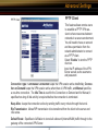
PPTP Server
PPTP Server
Please refer to the on screen
help balloons by clicking on the
‘Question Mark’ icons next to
each respective setting.
For detailed setup information
please see the specific Quick
Setup Guide for setting up your
VPN Server. The Quick Setup
Guide for setting up your VPN
Server was included in your
product’s original packaging. It
can be found on the AirStation
CD or on the Buffalo Technology
(USA) web site. http://www.buf
falotech.com
46
Advanced Settings
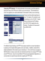
Dynamic DNS
Dynamic DNS is one of the
most effective ways of being
able to locate your network
from anywhere on the internet
anytime. Traditionally, IP Addresses and network information from your ISP change from
time to time. When this change
happens you can no longer
access your network by IP
Address. Dynamic DNS is software that runs on your router
that constantly sends network
Dynamic DNS
updates to a third party server. This means that you will always be able to find your network by way
of a Dynamic DNS hostname; regardless of your IP Address. This feature is critical when using
the Remote Gateway features of this router as it allows your users to always be able to find and
connect to your network via a vanity hostname. It is a requirement that you enroll in one of the two
Dynamic DNS providers we offer. TZO (Paid Service) and DynDNS (Free Service) are two of the
most popular Dynamic DNS providers. Please see their respective web pages (http://www.tzo.com
& http://www.dyndns.org) to create an account and learn more. Once you have created an account
at one of the sites, then you can Enable the Dynamic DNS Function.
From the pull-down menu select the service you just subscribed to.
47
Host Name - Input the domain host name set on the dynamic DNS server. For example: if the domain
you wish to use is [buffalo.dyndns.org] then the host name would be buffalo. The host name may be 64
alphanumerical characters including hypens.
Domain Name - Input the domain name set on the Dynamic DNS server. If the domain you wish to use
is [buffalo.dyndns.org] then the domain name would be dyndns.org. The domain name may be up to 64
alphanumeric characters including hyphens and periods.
User Name - Enter the account user name for the Dynamic DNS service you use. Up to 64 alphanumeric characters or symbols may be used.
Password - Enter the account password set on the Dynamic DNS service you use. Up to 64 alphanumerical characters or symbols may be used. For confirmation purposes the password must be entered
twice.
Expiration - This setting cannot be changed from its default setting. The default setting works for both
TZO and DynDNS.
IP Address Renewal Interval - With certain Dynamic DNS servers, the registered data has a set period
of time it stays active. After this set period the Dynamic DNS hostname is no longer valid This period of
time specifies the AirStation to renew your Dynamic DNS hostname after this many days. This prevents
the Dynamic DNS service from removing your hostname.
Caution: Dynamic DNS Services do not like being updated very frequently. In fact, some services will
cancel your subscription if you renew too often. It is recommended to use 24-35 days in this field as it is
an acceptable amount of time for a renewal, however, it is not too often that the Dynamic DNS service
will cancel/block your hostname. Additionally, anytime your network information changes from your ISP,
the Dynamic DNS service will automatically update, so setting this variable extremely low is not required.
48
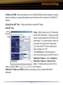
Advanced Settings
Network Settings
Routing
Setup
Routing Setup
RIP transmission to WAN - Allows RIP
transmission or None (no RIP) to WAN
RIP reception from WAN - Allows RIP
reception or None (no RIP) from WAN
RIP transmission to LAN - Allows RIP
transmission or None (no RIP) to LAN
RIP reception from LAN - Allows RIP
reception or None (no RIP) from LAN
RIP transmission to WAN - Allows RIP
transmission or None (no RIP) to WAN
Display current information - Allows
administrator to view and delete routing
information.
49
Advanced Settings
Add Routing
Table Entry
Click Add Route to Add a
Routing Table Entry
•Destination address - Network IP address and subnet
mask.
• Gateway - Address through
which the packet passes before it reaches the destination
address.
• Metric - Number of routers
(1-15) to be passed before the packet reaches its destination.
50
Advanced Settings
Address Translation
Address
Translation
Setup
Address Translation - Select
Enable or Disable. Address
Translation must be enabled
for client computers to connect to the Internet. Selecting
Enable enables the following
functions:
• IP Masquerade - When the
LAN computer connects to the
WAN side, the IP address of
LAN computer is dynamically
translated to become the WAN
IP address of the AirStation.
Multiple LAN computers can
share one WAN IP address to
access the Internet.
• Static IP address translation -When the WAN requests connection to the LAN, the WAN IP
address of the AirStation is translated into the IP address of the LAN computer.
Log Output - Set ‘Log Output’ to log discarded packets. Otherwise, a dropped packed is not
logged.
IPSec Pass-Through - Enables the AirStation’s ability to pass IPSec VPN data.
51
Advanced Settings
IP Address of DMZ - Allows administrator to set the DMZ (De-Militarized Zone) address. Incoming
packets containing no recognizable destination port information will be redirected to the DMZ’s IP
address.
Display/Delete NAT Table - Allows administrator to delete NAT tables.
Add NAT Table
Address
Translation
Setup
Group - Specify a group (up to 16 characters)
that the NAT rule belongs. Groups are simply
used to visually organize the NAT table for the
administrator. It is recommended to name the
group after the protocol that is being setup
(e.g. Group Name FTP when setting up address translation for FTP)
Click New Group to create new group or
select an existing group to add a NAT rule to it.
WAN Side IP Address - Select AirStation’s
WAN Side IP Address or Manual IP Address. For Manual setting, enter the IP address used by the WAN computer to connect to the local computer.
AirStation’s IP Address of WAN should be used unless you have multiple WAN side IP
addresses.
52
Advanced Settings
Some network applications (online games or streaming software) require adding Address Translation tables; consult the software’s documentation for port information).
Protocol (WAN):
• All - Selects all IP protocols.
• ICMP - Network Diagnostic Protocol (1).
• Manual - Specify the protocol number (0-65535).
• TCP/UDP - Enter port number for TCP or UDP protocols. If both TCP and UDP are required,
then separate entries are required.
LAN IP Address - Select Manual IP Address and enter the destination IP address of the LAN
computer; or select AirStation’s LAN IP Address.
Protocol (LAN) - Enter the destination port number. If left blank, the packets are transferred to
the same port number as the source port number. Typically the destination port should be left the
same as the source port.
• Click Add to NAT table. This will add the information to the NAT table. Once you have gone
through this process for every desired translation, you will need to press the Apply button on the
top of the screen to start the translating.
53
Advanced Settings
Packet Filter
Packet
Filter
Setup
Log Output - Select Output to
activate the packet filter log.
Packet Filter Information
Basic Rule - Click add/delete
basic rules. Place a check
mark next to the basic rule to
enable:
• Prohibit setup from wireless LAN - Prohibits administration from a wireless computer.
• Prohibit setup from wired
LAN - Prohibits administration
from a wired computer.
• Prohibit setup via wireless bridge access point - Prohibits a personal computer connected to
another AirStation in a wireless bridge.
• Prohibit NBT and Microsoft-DS routing - Prevent unexpected external access via Microsoft
network sharing. This prohibits computers on the internet from accessing shared resources on
Windows machines. It is recommended to leave this filter activated.
• Reject the IDENT request - The AirStation sends reject packets if it receives an IDENT request.
54
Advanced Settings
Basic Filter
Setting
Use this filter when the communication speed goes down using
a network application like E-mail,
FTP and WEB.
* If IDENT requests are forwarded to a LAN side client by
address translation setting (DMZ
or TCP port :113 ), this basic rule
is ignored.
55
Advanced Settings
IP Filter Settings - Limits the
type of packets allowed to pass
between the WAN and LAN.
The maximum number of rules
is 32.
• Operation - Packets from
WAN (or LAN), select ignored,
rejected, or accepted. Select
the operation to be performed
on the packets.
Packets from:
IP Filter
setting
• WAN side - packets coming from the WAN side will be filtered.
• LAN side - packets from the LAN side will be filtered.
Are :
• Ignored - Stop the packet and do not route it.
• Rejected - Return the rejected packet to the point of origin.
• Accepted - Pass the packet through.
• Destination IP Address - The IP address to be filtered.
• Source IP Address - The IP address designated for filtering. If all IP addresses must be filtered,
leave this box blank.
Warning: If administrator selects packet from LAN is Ignored or Rejected, the administrator will
56
Advanced Settings
no longer have access to the AirStation configuration screens. This function prohibits setup from
a wireless or wired computer. The AirStation can be returned to the factory default settings by
holding down the INIT button on the back of the unit for five seconds or until the red DIAG light
becomes solid.
Protocol - Mark and select a specific protocol. Select from all protocols, ICMP, arbitrary protocol
number and TCP/UDP protocol number.
• All - Selects all IP protocols.
• ICMP - Network Diagnostic Protocol (1).
• Manual - Enter protocol number (0-65535).
• TCP/UDP Destination Port - Select TCP or UDP, then enter port number.
Priority - Specify the priority an item. The smaller the number, the higher the priority.
Add MAC
Filter
setting
MAC Filter - Click Enter MAC
filter to enter MAC address.
Source MAC address -The
MAC address of the source of
the packets that will be filtered
may be set. Click Add rule
when complete.
57
Advanced Settings
■ Note: If configuring from a wireless computer, add your MAC address to the list of authorized
wireless LAN PCs. The MAC address must be in two-digit groups separated by colons.
Example: 00:40:26:00:11:22
Click Apply when settings are complete.
58
Advanced Settings
Intrusion
Detector
Setup
Intrusion Detector
The Intrusion Detector watch guards
and prevents unauthorized access
from the WAN (Internet)
This function also records information
on unauthorized access attempts
Intrusion Detector - Select Do not
use, Use or Use (Apply Packet filter
setting for Intrusion Detector setting).
IP Spoofing - Check Block to prevent
IP spoofing.
Threshold Value - Enter the number
(1-999) of suspect packets before the
notification occurs.
Notify by email
• Notification email address - Enter destination email address
• Sender email address - Enter the email address that will send the email. This is the name
that will appear as the sender when the email is read. This email can be made up (e.g.
DETECTOR@AIRSTATION
59
• Sender email server address - Enter the SMTP Server address.
• Receiving email server authorization - Enter the POP3 Server address, User name and Password.
This is only required if your SMTP server requires POP verification before it allows email to be sent.
Consult your ISP or mail server support for more information.
• Send test - Click Send to test notification; this will also save and commit the entries.
Pop-up notification - Pop-up window alert of unwanted activity. Client Manager must be installed and
running on a client machine to use this feature.
• Destination IP address - Enter the IP address to be notified. The LAN computer with this IP address
must have Buffalo’s Client Manager software installed and running for the verification to occur. If the
machine is off the verification will not be received, and the AirStation will NOT resend information.
Intrusion Detector information - displays log activity detected by the Intrusion Detector service.
60
Advanced Settings
UPnP
UPnP
Setting
Select Enable to enable
UPnP (Universal Plug and
Play). When a computer with
UPnP support connects to the
AirStation, that computer automatically receives configuration
information from the AirStation.
61
Advanced Settings
System
Information
Management - System Information
System information of the AirStation is
obtained here.
• Model name - Displays model and
firmware version
• AirStation Name - Displays AirStation
host name
• DHCP Server function - Displays On
or Off
• Wireless - Displays the wireless LAN
settings such as wireless MAC address
and wireless firmware. The wireless
MAC address is required for setting up
WDS with other access points. This is
the best place to determine the wireless
MAC address. If 125 Mbps AfterBurner
mode is enabled, then the [AfterBurner]
color will be red or grey. When it is red,
125 Mbps AfterBurner is running. When it is grey, 125 Mbps AfterBurner is enabled but not running due to
a client being connected at 54 Mbps or another access point running on the same channel.
• LAN - Displays the AirStation LAN settings .
• WAN - Displays the AirStation WAN settings and PPTP client settings if available.
• Default Gateway - Displays the default gateway settings.
62
Advanced Settings
• WAN side IP address auto acquisition - This is the method to acquire the IP address from the
WAN (Internet) side DHCP server. Press Release to release current DHCP WAN information. Press
Renew to obtain WAN information from the DHCP server. NOTE: If a manual IP is assigned to the
WAN port, this feature is not displayed.
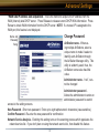
Change Password
Name and
Password
Setup
AirStation name - When using multiple AirStations, select a
unique name to make it easier to
identify each AirStation through
the AirStation Manager utility. This
utility is seldomly used, thus, the
AirStation name value has little
value.
Administrator name - “root”, cannot be changed
Administrator password Allows the administrator to enter an
administrator password to restrict
access to the setting screens.
New Password - Enter new password. Enter up to eight alphanumeric characters (case sensitive)
Confirm Password - Re-enter the new password for confirmation
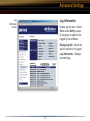
Network Service Analysis - Enabling this setting turns on the scanning process which populates the
network service list. If you don’t plan on using the network service list, then disable this feature.
63
Advanced Settings
Time setup
Time setup - Enter the current date and time, and click Set.
NTP - Net-
work Time Protocol. Select Use
or Do not use.
Time Setup
Screen
■ Note: If NTP is used, time is
set automatically.
NTP server name - Enter the
NTP server name
Update Time - Enter the time
interval (in hours) for the time
check frequency
Time Zone - Select local time
zone
Click Apply.
64
Advanced Settings
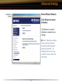
Packet Traffic
Information
Packet Traffic Information
Displays number of packets
sent and received for:
Wired WAN
Wired LAN
Wireless LAN
Click Refresh to start update
the transfer packet log.
65
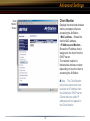
Advanced Settings
Client Monitor
Client
Monitor
Screen
Displays the wired and wireless
clients (computers) that are
accessing the AirStation.
• MAC address - Shows the
client’s MAC address.
• IP Address and Medium Shows the IP address that is
assigned to the client from the
DHCP server.
The network medium is
indicated as wireless or wired
depending on how the client is
accessing the AirStation.
■ Note: The Client Monitor
only shows clients that have
received an IP address from
the AirStation’s DHCP server.
Clients that have static IP
addresses will not appear in
the Client Monitor.
66
Advanced Settings
PING Test
PING Test
Performs a PING test from the
AirStation to a LAN or WAN
address.
Enter the target IP address and
click OK (e.g. 192.168.11.2
- OR- www.buffalotech.com)
If the test results in an error,
then verify you correctly
inputted the address and
check your connections.
67
Advanced Settings
Log
Information
Screen
Log Information
Display log info level - Select
Error and/or Notify to specify the types of reports to be
logged by the AirStation.
Display log info - Select the
specific reports to be logged.
Log information - Displays
recorded logs.
68
Advanced Settings
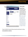
Syslog Transfer
Syslog
Transmitting
Screen
Select Use or Do not use
to enable or disable the
AirStation’s ability to transmit
information to a Syslog server.
• Syslog Server - Enter the IP
address of the Syslog server.
• Log Information Level
- Select Error and/or Notice to
specify the types of reports to
be sent to the Syslog server.
• Log Information - Select the
specific reports to be sent to
the Syslog server.
■ Note: A server on the network running a Syslog service
is required for this.
69
Advanced Settings
Save/Restore Settings
Save/
Restore
Settings
Screen
Save current settings - Click
Save to open the file saving
dialog and save the current
AirStation settings to a file.
Restored saved settings
- Restores settings from a file
that has been saved. Click
Choose file to select the saved
file and click Restore.
■ Note: If the setting file is
saved by a newer firmware than
the current one, the AirStation
can’t restore the settings.
70
Advanced Settings
Initialization/
Reboot
Reboot/Reload Defaults
Click Restart to reboot
AirStation
Click Restore to reset the
AirStation to default factory
settings.
■ Note: Resetting to default
factory settings will erase
all settings and passwords
previously entered. The
AirStation will return to the
condition it was in when first
purchased.
71
Advanced Settings
Firmware Update
Firmware
Update
Firmware file name
- Click Browse to browse
to the path and filename
for the new firmware. Click
Firmware Update to load
firmware to the AirStation.
■ Note: Firmware update
does not erase current
user settings. It does
however delete all of the
service information from
the Network Service List;
you will need to perform a
new service search after
you update the firmware.
Please visit the Buffalo Technology Web Page to download the latest firmwares free of charge.
http://www.buffalotech.com/wireless
72
Advanced Settings
AOSS
AOSS
Client Table - Displays the
clients connected via AOSS. The
‘Disconnect’ button disconnects
the client from the AOSS router
by using MAC Address filtering.
Once disconnected, the client will
still appear in the client list but
will appear as disconnected. The
client can then be re-enabled by
pressing the ‘Re-Enable’ button. A separate table exists for
connected Ethernet Converters.
The ‘Refresh’ button updates the
tables.
73
Advanced Settings
Manually specify the encryption type - This forces AOSS to
use a specified type of encryption. It is recommended to not
change this setting. If the setting
is changed then every client that
connects must have support for
that encryption type.
AOSS
AOSS Function - Click Enable
to allow the AirStation to use
AOSS function. Click Disable
to shut off the AOSS system.
Clicking Disable will disable the
AOSS button on the AirStation.
Start AOSS Process- Click AOSS icon to begin the AOSS sequence. This starts the AOSS process
just like pressing the AOSS button.
Stop AOSS Process- Click AOSS icon to stop AOSS operation. Stopping the AOSS function will turn
off AOSS and return the router to non-AOSS function.
74
Network Service List
Network
Service List
The Network Service List is the control center for your network. From within your LAN or from anywhere
in the world with a VPN connection (See VPN Quick Setup Guide) you can access this control center. From
this control center you can access convenient and easy to use services including: File Sharing, Remote
Control/Access of PC’s, Wake-On-LAN, FTP Servers, and Web Servers. To learn more about each independent feature, click on the ‘Question Mark’ logo next to ‘Network Service List’. It has a lot of informative
information regarding the services.
This hosts page can be reached by typing this URL into any browser connected to the network:
http://XXX.XX.XXX.XXX/hosts.htm (where XXX.XXX.XXX.XXX is the local IP Address of the AirStation; by
default this address is 192.168.12.1). Connecting to the VPN Server is easy, just launch the PPTP client as
instructed in the VPN Quick Setup Guide and use the Dynamic DNS hostname as the VPN address.
75
Network Service List
For easier access to the Network Service List, the Dynamic DNS hostname can be used for access to the
AirStation. However, for this to occur the ‘Remote Management Port Number’ must be configured on
‘Page 43’. By entering the value ‘80’ into the ‘Remote Management Port Number’ the Network Service List
can be accessed by typing: http://hostname.dyndns.org/hosts.htm -OR- http://hostname.tzo.com/hosts.com
depending on the service you’re subscribed with.
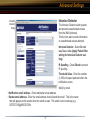
You can also log into your network service list
by just typing: http://hostname.dyndns.org OR- http://hostname.tzo.com depending on your
service. You will be prompted for your user name
and password. Once entered, you can click on the
large ‘Network Service List’ link. It is not recommended that you give this username and password
out to guests; this method of connection should
only be utilized by yourself or the administrator of
the network.
NOTE: By allowing remote management over a port number you allow access into your AirStation from the
Internet without a VPN connection. This is a potential security risk especially if you have not setup an administrator password on the AirStation. Even with a password set, a user on the internet could log into your
Network Service List and see all of the information regarding your network. Fortunately they would NOT
have access to remote control, file sharing, or Wake-On-LAN, but they will still be able to see what computers and devices are on your network. For some this may be considered a security risk.
76
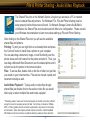
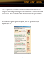
File & Printer Sharing - Audio/Video Playback
The Shared Files icon on the Network Service List gives you access to a PC or network
device’s shared files and printers. For Windows PC’s, File and Printer sharing must be
setup properly before this service will work. On Network Storage Centers like Buffalo’s
LinkStation, the Shared Files icon should work with little to no configuration. Please consult
your Windows documentation to learn more about setting up File and Printer Sharing.
After clicking on the Shared Files icon you will see the available
shared files and printers.
Printing: To print you can right click on a shared printer and press
the ‘Connect’ button to install it as a printer on your computer.
You can also drag a document, image, or text file directly over the
printer share and it will connect to the printer and print it. Thus, you
can drag a Microsoft Word Document over the shared printer and it
will print out on the printer in the remote location.
Files: To access files, double click on the file or folder icon just like
you would on your local machine. Files can be moved, copied, and
renamed normally as well.
Audio/Video Playback*: To play audio or video files through
shared files just double click on the audio or video file you would
like to play or select multiple files and create a playlist.
* Streaming audio or video over the internet requires an internet connection sufficient
enough to move the necessary amount of data. For instance, to stream a 128kbps
MP3, a 150k or greater internet connection would need to be present on the remote
and local side. Video often requires a faster internet connection. Most broadband
DSL/Cable connections will have no problem streaming audio and most video files.
77
Remote Control - TightVNC
TightVNC is the recommended Remote Control Software. This icon will appear on any
computer on the Network Service List that is running the VNC software. This icon provides a
one-click process to obtaining access to the PC.
Installing TightVNC Software for the Desktop: Installing TightVNC is very easy, just insert the CD-ROM
that came with your AirStation product and install the software. The on-screen menus will guide you through
the setup process.
Non-Windows Platforms: TightVNC utilizes the open-source VNC standard, thus any VNC software will
work with the AirStation. Currently only TightVNC and Windows are supported but customers can install
other open-source VNC applications for Macintosh, Linux, and other systems. If the server runs on port
5800 then the ‘VNC Remote’ icon will appear on the Network Service List.
Additionally, there are VNC comptible clients for all systems including PalmOS and PocketPC. Thus, with
PPTP VPN connection software, a handheld user (PalmOS and PocketPC) could theoretically connect in
and control their home or office PC’s from their handheld; assuming the handheld has some sort of internet
connection. Buffalo Technology (USA) Inc. does not support users in making VNC work in anything but
Windows.
78
Remote Control - TightVNC
Once you click on the ‘VNC Remote’ link you will be prompted for a password. If a password was not set during the installation, then this step may
not occur. Enter the password and press the ‘OK’ button.
It is recommended to change the remote PC’s desktop size to 800x600 for the
best viewing experience. This change can be made after connecting to the
remote PC by right clicking on the desktop, selecting properties, and pressing
on the ‘Settings’ tab.
Once logged on, you will have full, complete control over the PC in question. On the top bar there are a series of buttons that perform various
tasks:
Disconnect: Ends the TightVNC remote control session immediately.
Options: Brings up the options menu (see below).
Clipboard: Brings up the remote PC’s clipboard so you can copy/paste
into the connecting machine.
Send Ctrl-Alt-Delete: Sends an Alt-Ctrl-Del signal to the remote computer
Refresh: Refreshes what is on the screen
There are several options for TightVNC. It is recommended to leave them
all at their default values. However, the following settings may be changed
if desired:
JPEG Image Quality: Lower number = faster connection; lower image
quality. Higher number = slower connection; better image quality.
View Only: If enabled, you can only see what happens on the screen, not
interact with the desktop.
79
Remote Control - TightVNC
There is a TightVNC client available on the CD-ROM that came with your AirStation. It provides more
configuration options including screen scaling. If it is used, the client will have to be launched after the VPN
session is created. After it is launched the IP Address will have to be entered manually into the software.
For more information regarding TightVNC and compatibility, please view TightVNC’s web page at
http://www.tightvnc.com
80
Specifications
Additional Information
For more information, please consult:
• The AirStation website at:
http://www.buffalotech.com - for frequently asked questions (FAQ’s) and Software Updates.
WZR-RS-G54 BASE STATION SPECIFICATIONS
Physical Specifications
Dimensions W3 x H6.75 x D6.1in. (76 x 171 x 155mm)
Weight 1 lb. (620g)
Temperature & Humidity
Operation 0˚ to 40˚ C
Maximum humidity 80%
Transit/Storage 0˚ to 40˚ C maximum humidity 80% (no condensation)
Power Characteristics
Transmit Mode 1.1A (Nominal),
Power Supply 3.3 V
81
Specifications
Regulatory Information
Wireless communication is often subject to local radio regulations. Although AirStation wireless
networking products have been designed for operation in the license-free 2.4 GHz band, local radio
regulations may impose limitations on the use of wireless communication equipment.
Networking Characteristics
Compatibility
• IEEE802.11g/b Standard for Wireless LANs (125 High Speed Mode also Available)
• Wi-Fi (Wireless Fidelity) certified by the Wi-Fi Alliance.
Host Operating System
Microsoft Windows® 98SE/ME/NT4.0/2000/XP, Unix, Linux and MacOS
Media Access Protocol
Wired - CSMD/CD (Collision Detection)
Wireless - CSMD/CA (Collision Avoidance) with Acknowledgment (ACK)
Radio Characteristics
RF Frequency Band 2.4 GHz (2400-2483 MHz)
11 selectable channels (3 non-overlapping)
82
Specifications
Modulation Technique Direct Sequence Spread Spectrum
• ODFM for High Transmit Rate
• DQPSK for Standard Transmit Rate
• DBPSK for Low Transmit Rate
Spreading 11-chip Barker Sequence
Nominal Output Power 13.5 dBm
Transmit Rate / Range
High Speed 54 Mbps (125 Mbps in 125 High Speed Mode)
Medium Speed 36 Mbps (96 Mbps in 125 High Speed Mode)
Standard Speed 2 Mbps
Low Speed 1 Mbps
Open Office Environment
160 m (525 ft.)
270 m (885 ft.)
83
Specifications
400 m (1300 ft.)
550 m (1750 ft.)
Semi-Open Office Environment
50 m (165 ft.)
70 m (230 ft.)
90 m (300 ft.)
115 m (375 ft.)
Closed Office
25 m (80 ft.)
35 m (115 ft.)
40 m (130 ft.)
50 m (165 ft.)
Receiver Sensitivity -83 dBm -87 dBm -91 dBm -94 dBm (depends on data rate)
Delay Spread (at FER of <1%) 65 ns 225 ns 400 ns 500 ns (depends on data rate)
• The range of wireless devices can be affected by metal surfaces, solid high-density materials
and obstacles in the signal path.
84
Specifications
Table “Radio Characteristics” lists the typical ranges when used indoors:
• In Open Office environments, clients can “see” each other, i.e. there are no physical obstructions between them.
• In Semi-open Office environments, work space is separated by room dividers; client cards are
at desktop level.
• In Closed Office environments, workspace is separated by floor-to-ceiling brick walls.
■ Note: The range values listed in Table “Radio Characteristics” are typical distances as
measured at Buffalo Technology AirStation laboratories. These values are provided for your
guidance but may vary according to the actual radio conditions at the location where the AirStation
product is installed.
AirStation IEEE 802.11 Channel Sets
The range of the wireless signal is related to the Transmit Rate of the wireless communication.
Communications at a lower Transmit range may travel longer distances.
Center Channel ID FCC
1 2412 2 2417 3 2422 4 2427 5 2432 6 2437 7 2442 8 2447 9 2452 10 2457 11 2462
11 default channel
85
Troubleshooting
Common Problems:
• Out of range, client cannot connect to the AirStation.
• Configuration mismatch, client cannot connect to the AirStation.
• Absence or conflict with the Client Driver.
• Conflict of another device with the AirStation hardware.
B.1.1 LED Activity B
Monitoring LED activity helps identify problems.
• Power LED should be GREEN,
• Wireless LED should be GREEN if the line is active. If is it blinking GREEN, wireless communication is active.
• Ethernet LED should be GREEN (100Mbps) or AMBER (10Mbps) while the communication is active.
DIAG LED Activity
Unplug the power for three seconds. Plug the power back in to monitor the DIAG LEDs during start-up.
If any symptoms match section B.1.1, call the Buffalo Tech Support line 24 hours a day, 7 days a week
at 866-752-6210 or email [email protected].
86
Troubleshooting
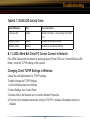
Table B.1.1 DIAG LED Activity Table
DIAG LED Display
Time
Description/Action
Continuous Red
Starting
RAM Error Red flash, 2 times Starting Flash ROM
Error
Red flash, 3 times
Starting
A problem on the wired LAN side
Red flash, 4 times
Starting
A problem on the wireless LAN side
B. 1.2 LEDs Work But Client PC Cannot Connect to Network
If the LEDs indicate that the network is working properly (Power LED is on, Transmit/Receive LED
blinks), check the TCP/IP settings of the network.
Changing Client TCP/IP Settings in Windows
Consult the LAN Administrator for TCP/IP settings.
To add or change the TCP/IP Settings:
1. On the Windows task bar click Start.
2. Select Settings, then Control Panel.
3. Double-click on the Network icon to view the Network Properties.
4. From the list of installed components, verify the TCP/IP => wireless LAN adapter protocol is
installed.
87
Troubleshooting
• If the wireless adapter protocol is not yet installed, click the Add button and select the TCP/IP
protocol from the list. Refer to Windows Help for more information.
• If the wireless adapter protocol is installed, select the protocol and click the Properties button.
Verify the parameters match the settings provided by your LAN Administrator. Make changes
if necessary, and click OK.
5. When or if prompted, restart your computer.
B. 1.3 Other Problems
Please refer to www.buffalotech.com for further reference materials.
88
Troubleshooting
Troubleshooting WDS (Step-by-Step Instructions)
The most common issue with WDS installations is using the wrong MAC address. The proper MAC Address for the access points is the ‘Wireless MAC Address’. The best place to document this is under the
‘System Information’ section of the configuration web page. For proper setup, please continue reading
this document.
Problem:
Communication problems with WDS (wireless bridging/repeating).
Cause:
WDS is a very complex bridging system, and it is not part of the 802.11b or 802.11g standard.
Restrictions:
Please verify that the following conditions are met (if just one condition is not satisfied, then WDS cannot be used on the wireless network):
1. All wireless access points in the wireless bridge need to be from the same vendor (e.g. all Buffalo
access points).
(At time of publication, the Apple Airport Extreme WILL work in WDS with Buffalo G54 access points.)
2. No single access point can communicate with more then six other access points in the wireless
bridge.Good Practices:proper location.
89
Troubleshooting
The following is a list of good practices with WDS:
1. Start the wireless bridge system with only two access points and then add more access points.
2. Setup all access points in the wireless bridge in close proximity before they are deployed to their
proper location.
3. Only one access point in the wireless bridge should be serving DHCP and routing services unless a
routed wired network exists.
Proper Setup:
Please follow the following steps to properly setup WDS.
1. It is recommended that all access points in the bridge are reset to their factory default settings. This
is done by holding the INIT button on the rear of the access point down for 5-10 seconds.
2. Login to the first access point in the wireless bridge (this should be the DHCP server enabled access point if there is not already a routed wired network).
3. Click on the ‘Advanced’ button.
4. The wireless settings page will appear. Select the proper settings for the wireless network. Record
all settings on a piece of paper. All settings except for the SSID need to be identical amongst all access points in the bridge.
(If roaming is desired, then make sure the SSID settings need to be identical as well). Press the ‘Set’
button if any changes are made.
(If the IP address was changed, then reconnecting to the access point for configuration will require accessing it via its new IP address in a web browser (e.g. http://NEW_IP_ADDRESS).
90
Troubleshooting
5. Click on the ‘LAN port’ link on the left.
6. Check that the ‘LAN side IP address’ values are correct for your network, or leave them as default.
Record the ‘LAN side IP address’. Press the ‘Set’ button if any settings on this page have been set.
7. Click on the ‘Management’ link on the left.
8. The System Information page will appear. In the Wireless section of the table record the MAC address (including the :’s). Please make sure the MAC address is recorded from the Wireless section
and not the other sections.
9. Logout of the access point by clicking on the ‘Logout’ link on the left. Close the browser window.
10. Login to the second access point in the wireless bridge.
11. Click on the ‘Advanced’ button.
12. The wireless settings page will appear. Select the proper settings for the wireless network. Refer to
the settings recorded from the first access point. All settings except for the SSID need to be identical
amongst all access points in the bridge.
(If roaming is desired, then make sure the SSID settings need to be identical as well).
13. Click on the ‘LAN port’ link on the left.
14. Make sure that the ‘LAN side IP address’ ‘IP address’ setting is different then the first access point.
The IP addresses cannot be the same, but they should be on the same network. It is recommended
that the IP address of the second access point is one higher then that of the first access point. Thus,
if access point one’s address is 1.1.1.1, then access point two’s address should be 1.1.1.2. If there is
a ‘DHCP server function’ setting on this page, then make sure to set it to ‘Do not use’ or to ‘Disabled’.
Press the ‘Set’ button when finished.
91
Troubleshooting
15. Click on the ‘Wireless bridge (WDS)’ link on the left.
16. Enable the WDS function and press the ‘Set’ button.
17. Enter the Wireless MAC Address of the first access point (which was recorded on Step 8) into the
field that say ‘MAC Address of AirStation(Wireless)’ (include the :’s). Press the ‘Add’ button.
18. The Wireless MAC address inputted on the step above will appear in the ‘Connected AirStation’
table. Please check that the checkbox under enable is checked, and then press the ‘Enable marked
item’ button.
19. At the top of the page, press the ‘Apply’ button.
20. Once the router has rebooted, click on the ‘Management’ tab on the left.
21. The System Information page will appear. In the Wireless section of the table record the MAC address (including the :’s). Please make sure the MAC address is recorded from the Wireless section
and not the other sections.
22. Logout of the access point by clicking on the ‘Logout’ link on the left. Close the browser window.
23. Login to access point one again.
24. Click on the ‘Advanced’ button.
25. Click on the ‘Wireless bridge (WDS)’ link on the left.
26. Enable the WDS function and press the ‘Set’ button.
27. Enter the Wireless MAC Address of the first access point (which was recorded on Step 21) into the
field that say ‘MAC Address of AirStation(Wireless)’ (include the :’s). Press the ‘Add’ button.
92
Troubleshooting
29. At the top of the page, press the ‘Apply’ button.
30. Once the router has rebooted, click on the ‘Management’ tab on the left.
31. Click on the ‘PING test’ link on the left.
32. In the ‘Destination’ field enter the IP address of the second access point and press the ‘OK’ button.
a. If the ‘Result’ section of the table reports information like, “1st: 64 bytes from IP_ADDRESS” then
the WDS bridge is effectively working.
b. If the ‘Result’ section of the table reports “Destination Host Unreachable”, then an error has occurred during the setup.
WDS is a complicated bridging system with a lot of variables. If there are still problems with WDS configuration on the network, then please call our 24/7 technical support line at 1-866-752-6210.
93
Glossary
10BaseT or 100BaseTx: 802.3 based Ethernet network that uses UTP (Unshielded twisted
pair) cable and a star topology. 10 is 10 Mbps
and 100 is 100 Mbps.
Cross-Over Wiring: A UTP cable that has its
transmit and receive pair crossed to allow communications between two devices.
802.1x: The standard for wireless LAN authentication used between an AP and a client. 802.1x
with EAP will initiate key handling.
Ad-Hoc Network: The wireless network based
on a peer-to-peer communications session.
Also referred to as AdHoc.
DCE (Data Communications Equipment):
Hardware used for communication with a Data
Terminal Equipment (DTE) device.
Default Gateway: The IP Address of either the
nearest router or server for the LAN.
Default Parameter: Parameter set by the
manufacturer.
Bandwidth: The transmission capacity of a
computer or a communication channel, stated in
Megabits per second (Mbps).
Destination Address: The address portion of
a packet that identifies the intended recipient
station.
BSS (Basic Service Set): An 802.11 networking framework that includes an Access Point.
DHCP (Dynamic Host Configuration Protocol): Based on BOOTP, it uses a pool of IP
addresses, which it assigns to each device connected to it, and retrieves the address when the
device becomes dormant for a period of time.
Bus Mastering: A system in which the specified Input/Output device (e.g. NIC Card) can
perform tasks without the intervention of the
CPU.
DNS (Domain Name System): System used
to map readable machine names into IP addresses
Client: A PC or workstation on a network.
94
Glossary
Driver: Software that interfaces a computer
with a specific hardware device.
Ethernet cable: A wire similar to telephone
cable that carries signals between Ethernet
devices.
DSSS (Direct Sequence Spread Spectrum):
Method of spreading a wireless signal into wide
frequency bandwidth.
File and Print Sharing: A Microsoft application
that allows computers on a network to share
files and printers.
DTE (Data Terminal Equipment): Device that
con10BaseT or 100BaseTx: 802.3 based
Ethernet network that uses UTP (Unshielded
twisted pair) cable and a star topology. 10 is 10
Mbps and 100 is 100 Mbps.
Firmware: Programming inserted into programmable read-only memory, thus becoming a
permanent part of a computing device.
Frame: A fixed block of data, transmitted as a
single entity. Also referred to as packet.
Dynamic IP Address: An IP address that is
automatically assigned to a client station in a
TCP/IP network, typically by a DHCP server.
Full-Duplex: To transmit on the same channel
in both directions simultaneously.
ESS (Extended Service Set): A set of two
or more BSSs that form a single sub-network.
SSID is user identification used in the ESS LAN
configuration.
Half-duplex: To transmit on the same channel
in both directions, one direction at a time.
Hub: A device which allows connection of computers and other devices to form a LAN.
Ethernet: The most widely used architecture
for Local Area Networks (LANs). It is a sharedmedia network architecture. The IEEE 802.3
standard details its functionality.
IEEE (Institute of Electrical and Electronics
Engineers): The professional organization
which promotes development of electronics
technology.
95
Glossary
IP (Internet Protocol) Address: A unique 32binary-digit number that identifies each sender
or receiver of information sent in packets.
Mbps (Mega Bits Per Second): A measurement of millions of bits per second.
MDI/X (Media Dependent Interface/Crossover): Port on a network hub or switch that
crosses the incoming transmit lines with the
outgoing receive lines.
Infrastructure: A wireless network or other
small network in which the wireless network
devices are made a part of the network through
the Access Point.
MHz (MegaHertz): One million cycles per
second.
ISP (Internet Service Provider): A company
that provides access to the Internet and other
related services.
IV (Initialization Vector): The header section
of an encrypted message packet.
NAT (Network Address Translation): An internet standard that enables a LAN to use one set
of IP addresses for internal traffic and a second
set for external traffic.
LAN (Local Area Network): A group of computers and peripheral devices connected to
share resources.
NIC (Network Interface Card): An expansion
card connected to a computer so the computer
can be connected to a network.
LED (Light Emitting Diode): The lights on
a hardware device representing the activity
through the ports.
Packet: A block of data that is transferred as a
single unit, also called a frame or a block.
Packet Filtering: Discarding unwanted network traffic based on its originating address or
its type.
MAC (Medium Access Control) Address:
A unique number that distinguishes network
cards.
96
Glossary
mation between computers.
PCI (Peripheral Component Interconnect): A
bus that is connected directly to the CPU.
RADIUS (Remote Authentication Dial In User
Service): A server that issues authentication key to
clients.
PCMCIA (Personal Computer Memory Card
International Association) Card: Removable module that adds features to a portable
computer.
RAM (Random Access Memory): Non-permanent
memory.
Ping (Packet Internet Groper): An Internet
utility used to determine whether a particular IP
address is online.
Repeater Hub: A device that collects, strengthens
and transmits information to all connected devices,
allowing the network to be extended to accommodate additional workstations.
Plug and Play: Hardware that, once installed (“plugged in”), can immediately be
used (“played”), as opposed to hardware that
requires manual configuration.
RC4: The encryption algorithm that is used in WEP.
RJ-45 connector: An 8-pin connector used between a twisted pair cable and a data transmission
device.
PoE (Power over Ethernet): A mechanism
to send DC power to a device using a CAT5
Ethernet cable.
ROM (Read Only Memory): Permanent memory.
Router: Device that can connect individual LANs
and remote sites to a server.
PPPoE (Point-to-Point Protocol over Ethernet): A specification for connecting users on an
Ethernet line to the Internet through a common
broadband medium.
Roaming: The ability to use a wireless device while
moving from one access point to another without
losing the connection.
Protocol: A standard way of exchanging infor97
Glossary
Script: A macro or batch file containing instructions and used by a computer to perform a task.
TCP/IP (Transmission Control Protocol/Internet Protocol: Protocol used by computers
when communicating across the Internet or
Intranet.
Server: Any computer that makes files or
peripheral devices available to users of the
network and has a resident Network OS.
TKIP (Temporal Key Integrity Protocol): An
encryption method replacing WEP. TKIP uses
random IV and frequent key exchanges.
SMTP (Simple Mail Transfer Protocol): The
protocol used to define and deliver electronic
mail (E-mail) from one location to another.
Topology: The shape of a LAN (Local Area
Network) or other communications system.
SNMP (Simple Network Management Protocol: An application layer protocol that outlines
the formal structure for communication among
network devices.
Twisted Pair: Cable that comprises 2 or more
pair of insulated wires twisted together.
UDP (User Datagram Protocol): A communication method (protocol) that offers a
limited amount of service when messages are
exchanged between computers in a network.
UDP is used as an alternative to TCP/IP.
Static IP Address: A permanent IP address is
assigned to a node in a TCP/IP network. Also
known as global IP.
STP (Shielded Twisted Pair): Twisted Pair
cable wrapped in a metal sheath to provide extra protection from external interfering signals.
Uplink: Link to the next level up in a communication hierarchy.
Subnet Mask: An eight-byte address divided
into 4 parts separated by periods.
UTP (Unshielded Twisted Pair) cable: Two or
more unshielded wires twisted together to form
a cable.
98
Glossary
WAN (Wide Area Network): A networking system covering a wide geographical area.
WEP (Wired Equivalent Privacy): An encryption method based on 64 or 128-bit algorithm.
Web Browser: A software program that allows
viewing of web pages.
Wi-Fi (Wireless Fidelity): An organization that
tests and assures interoperability among WLAN
devices.
Wire Speed: The maximum speed at which a
given packet can be transferred using Ethernet
and Fast Ethernet standard specifications.
WLAN (Wireless LAN): A LAN topology using
wireless devices.
VPN (Virtual Private Network): A security
method to connect remote LAN users to a corporate LAN system.
99
FCC / CE Information
Federal Communication Commission Interference Statement
This equipment has been tested and found to comply with the limits for a Class B digital device,
pursuant to Part 15 of the FCC Rules. These limits are designed to provide reasonable protection
against harmful interference in a residential installation. This equipment generates, uses and can
radiate radio frequency energy and, if not installed and used in accordance with the instructions, may
cause harmful interference to radio communications. However, there is no guarantee that interference
will not occur in a particular installation. If this equipment does cause harmful interference to radio
or television reception, which can be determined by turning the equipment off and on, the user is
encouraged to try to correct the interference by one of the following measures:
• Reorient or relocate the receiving antenna.
• Increase the separation between the equipment and receiver.
• Connect the equipment into an outlet on a circuit different from that to which the receiver is connected.
• Consult the dealer or an experienced radio/TV technician for help.
FCC Caution: To assure continued compliance, (example - use only shielded interface cables when
connecting to computer or peripheral devices). Any changes or modifications not expressly approved
by the party responsible for compliance could void the user’s authority to operate this equipment.
This device complies with Part 15 of the FCC Rules. Operation is subject to the following two conditions:
(1) This device may not cause harmful interference, and (2) this device must accept any interference
received, including interference that may cause undesired operation.
100
FCC / CE Information
IMPORTANT NOTE:
Federal Communication Commission Interference Statement
This equipment has been tested and found to comply with the limits for a Class B digital device,
pursuant to Part 15 of the FCC Rules. These limits are designed to provide reasonable protection
against harmful interference in a residential installation. This equipment generates, uses and can
radiate radio frequency energy and, if not installed and used in accordance with the instructions, may
cause harmful interference to radio communications. However, there is no guarantee that interference
will not occur in a particular installation. If this equipment does cause harmful interference to radio
or television reception, which can be determined by turning the equipment off and on, the user is
encouraged to try to correct the interference by one of the following measures:
-Reorient or relocate the receiving antenna.
-Increase the separation between the equipment and receiver.
-Connect the equipment into an outlet on a circuit different from that
to which the receiver is connected.
-Consult the dealer or an experienced radio/TV technician for help.
This device complies with Part 15 of the FCC Rules. Operation is subject to the following two conditions:
(1) This device may not cause harmful interference, and (2) this device must accept any interference
received, including interference that may cause undesired operation.
FCC Caution: Any changes or modifications not expressly approved by the party responsible for
compliance could void the user’s authority to operate this equipment.
101
FCC / CE Information
FCC RF Radiation Exposure Statement:
This equipment complies with FCC radiation exposure limits set forth for an uncontrolled environment.
This equipment should be installed and operated with minimum distance 20cm between the radiator &
your body. This transmitter must not be co-located or operating in conjunction with any other antenna
or transmitter.
BUFFALO declared that WZR-RS-G54 is limited in CH1~11 by specified firmware controlled in
USA.
Safety
This equipment is designed with the utmost care for the safety of those who install and use it.
However, special attention must be paid to the dangers of electric shock and static electricity when
working with electrical equipment. All guidelines of this manual and of the computer manufacturer
must therefore be allowed at all times to ensure the safe use of the equipment.
102
FCC / CE Information
Important Notice:
This device is a 2.4 GHz wireless LAN transceiver, intended for indoor home and office use in all
EU and EFTA member states.
Intended use
This device is a 2.4 GHz wireless LAN transceiver, intended for indoor home and office use in all
EU and EFTA member states.
EU Countries intended for use
This device is intended for indoor Home and office use in the following countries,
Austria, Belgium, Germany, Denmark, Spain, Greece, France, Finland, Italy, Ireland, Luxembourg,
The Netherlands, Portugal, Sweden, United Kingdom, Cyprus, Czech Republic, Estonia, Hungry,
Latvia, Lithuania, Malta, Poland, Slovak Republic and Slovenia.
The device is also authorised for use in all EFTA member states Iceland, Liechtenstein, Norway and
Switzerland.
EU countries not intended for use
None
103
FCC / CE Information
Potential restrictive use
This device is a 2.4 GHz wireless LAN transceiver, intended for indoor home and office use in all
EU and EFTA member states, except in France, Belgium and Italy where restrictive use applies.
In Italy the end-user should apply for a license at the national spectrum authorities in order to
obtain an authorization to use the device for setting up outdoor radio links.
In Belgium there is a restriction in outdoor use. The frequency range in which outdoor operation in
Belgium is permitted is 2460 – 2483.5 MHz.
This device may not be used for setting up outdoor radio links in France. For more information see
http://www.anfr.fr/ and/or http://www.art-telecom.fr
104
Warranty Information
Buffalo Technology (Melco Inc.) products comes with a two-year limited warranty from the date of
purchase. Buffalo Technology (Melco Inc.) warrants to the original purchaser the product; good operating condition for the warranty period. This warranty does not include non-Buffalo Technology (Melco
Inc.) installed components. If the Buffalo product malfunctions during the warranty period, Buffalo
Technology/(Melco Inc.) will, replace the unit, provided the unit has not been subjected to misuse,
abuse, or non-Buffalo Technology/(Melco Inc.) authorized alteration, modifications or repair.
All expressed and implied warranties for the Buffalo Technology (Melco Inc) product line including,
but not limited to, the warranties of merchantability and fitness of a particular purpose are limited in
duration to the above period.
Under no circumstances shall Buffalo Technology/(Melco Inc.) be liable in any way to the user for
damages, including any lost profits, lost savings or other incidental or consequential damages arising
out of the use of, or inability to use the Buffalo products.
In no event shall Buffalo Technology/(Melco Inc.) liability exceed the price paid for the product from
direct, indirect, special, incidental, or consequential damages resulting from the use of the product, its
accompanying software, or its documentation. Buffalo Technology/(Melco Inc.) does not offer refunds
for any product.
@ 2003 Buffalo Technology (Melco, Inc.)
105
Contact Information
ADDRESS
Buffalo Technology (USA), Inc.
4030 West Braker Lane, Suite 120
Austin, TX 78759-5319
GENERAL INQUIRIES
Monday through Friday
8:30am-5:30pm CST
Direct: 512-794-8533 | Toll-free: 800-456-9799 | Fax: 512-794-8520 | Email: sales@buffalotech.
com
TECHNICAL SUPPORT
North American Technical Support by phone is available 24 hours a day, 7 days a week. (USA and
Canada).
Toll-free: (866) 752-6210 | Email: [email protected]
* When operating in High-Speed Mode, this Wi-Fi device achieves an actual throughput of up to 34.1 Mbps, which is the
equivalent throughput of a system following 802.11g protocol and operating at a signaling rate of 125 Mbps.
106
4030 W. Braker Ln. Suite 120
Austin, Texas 78759
Tel: 800-456-9799
Fax: 512-794-8606
Technical Support is available 24 hours a day, 7 days a week
(USA / Canada)
Toll-Free: 866-752-6210
email: [email protected]
©2004, Buffalo Technology (USA), Inc.
107