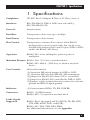
1
DECEMBER 2001
IC107A-R3
IC107AE-R3
IC107C-R3
RS-232↔RS-422/485 Converter
(Data Only)
CUSTOMER
SUPPORT
INFORMATION
Order toll-free in the U.S.: Call 877-877-BBOX (outside U.S. call 724-746-5500)
FREE technical support 24 hours a day, 7 days a week: Call 724-746-5500 or fax 724-746-0746
Mailing address: Black Box Corporation, 1000 Park Drive, Lawrence, PA 15055-1018
Web site: www.blackbox.com • E-mail: [email protected]
FCC/IC RFI STATEMENTS, DECLARATION OF CONFORMITY
FEDERAL COMMUNICATIONS COMMISSION AND INDUSTRY CANADA
RADIO-FREQUENCY INTERFERENCE STATEMENTS
This equipment generates, uses, and can radiate radio-frequency energy, and if not
installed and used properly, that is, in strict accordance with the manufacturer’s
instructions, may cause interference to radio communication. It has been tested
and found to comply with the limits for a Class A computing device in accordance
with the specifications in Subpart B of Part 15 of FCC rules, which are designed to
provide reasonable protection against such interference when the equipment is
operated in a commercial environment. Operation of this equipment in a
residential area is likely to cause interference, in which case the user at his own
expense will be required to take whatever measures may be necessary to correct
the interference.
Changes or modifications not expressly approved by the party responsible
for compliance could void the user’s authority to operate the equipment.
This digital apparatus does not exceed the Class A limits for radio noise emission from
digital apparatus set out in the Radio Interference Regulation of Industry Canada.
Le présent appareil numérique n’émet pas de bruits radioélectriques dépassant les limites
applicables aux appareils numériques de la classe A prescrites dans le Règlement sur le
brouillage radioélectrique publié par Industrie Canada.
EUROPEAN UNION DECLARATION OF CONFORMITY
This equipment complies with the requirements of the European EMC Directive
89/336/EEC.
1
RS-232↔RS-422/485 CONVERTER (DATA ONLY)
NORMAS OFICIALES MEXICANAS (NOM)
ELECTRICAL SAFETY STATEMENT
INSTRUCCIONES DE SEGURIDAD
1. Todas las instrucciones de seguridad y operación deberán ser leídas antes de
que el aparato eléctrico sea operado.
2. Las instrucciones de seguridad y operación deberán ser guardadas para
referencia futura.
3. Todas las advertencias en el aparato eléctrico y en sus instrucciones de
operación deben ser respetadas.
4. Todas las instrucciones de operación y uso deben ser seguidas.
5. El aparato eléctrico no deberá ser usado cerca del agua—por ejemplo, cerca
de la tina de baño, lavabo, sótano mojado o cerca de una alberca, etc..
6. El aparato eléctrico debe ser usado únicamente con carritos o pedestales que
sean recomendados por el fabricante.
7. El aparato eléctrico debe ser montado a la pared o al techo sólo como sea
recomendado por el fabricante.
8. Servicio—El usuario no debe intentar dar servicio al equipo eléctrico más allá
a lo descrito en las instrucciones de operación. Todo otro servicio deberá ser
referido a personal de servicio calificado.
9. El aparato eléctrico debe ser situado de tal manera que su posición no
interfiera su uso. La colocación del aparato eléctrico sobre una cama, sofá,
alfombra o superficie similar puede bloquea la ventilación, no se debe colocar
en libreros o gabinetes que impidan el flujo de aire por los orificios de
ventilación.
10. El equipo eléctrico deber ser situado fuera del alcance de fuentes de calor
como radiadores, registros de calor, estufas u otros aparatos (incluyendo
amplificadores) que producen calor.
11. El aparato eléctrico deberá ser connectado a una fuente de poder sólo del
tipo descrito en el instructivo de operación, o como se indique en el aparato.
2
NOM STATEMENT, TRADEMARKS
12. Precaución debe ser tomada de tal manera que la tierra fisica y la polarización
del equipo no sea eliminada.
13. Los cables de la fuente de poder deben ser guiados de tal manera que no
sean pisados ni pellizcados por objetos colocados sobre o contra ellos,
poniendo particular atención a los contactos y receptáculos donde salen del
aparato.
14. El equipo eléctrico debe ser limpiado únicamente de acuerdo a las
recomendaciones del fabricante.
15. En caso de existir, una antena externa deberá ser localizada lejos de las lineas
de energia.
16. El cable de corriente deberá ser desconectado del cuando el equipo no sea
usado por un largo periodo de tiempo.
17. Cuidado debe ser tomado de tal manera que objectos liquidos no sean
derramados sobre la cubierta u orificios de ventilación.
18. Servicio por personal calificado deberá ser provisto cuando:
A: El cable de poder o el contacto ha sido dañado; u
B: Objectos han caído o líquido ha sido derramado dentro del aparato; o
C: El aparato ha sido expuesto a la lluvia; o
D: El aparato parece no operar normalmente o muestra un cambio en su
desempeño; o
E: El aparato ha sido tirado o su cubierta ha sido dañada.
TRADEMARKS USED IN THIS MANUAL
BLACK BOX and the
Corporation.
logo are registered trademarks of Black Box
Any other trademarks mentioned in this manual are acknowledged to be the property of the
trademark owners.
3
RS-232↔RS-422/485 CONVERTER (DATA ONLY)
Contents
Chapter
Page
1.
Specifications ............................................................................................. 5
2.
Introduction ............................................................................................... 7
3.
Configuration ............................................................................................. 8
4.
Installation ................................................................................................ 10
5.
Operation ................................................................................................. 11
5.1 RS-232 Circuitry ................................................................................ 11
5.2 RS-422/485 Circuitry ........................................................................ 13
6.
Troubleshooting ...................................................................................... 14
6.1 Calling Black Box .............................................................................. 14
6.2 Shipping and Packaging ................................................................... 14
Appendix: Pinouts .......................................................................................... 15
4
CHAPTER 1: Specifications
1. Specifications
Compliance:
CE; FCC Part 15 Subpart B Class A, IC Class/classe A
Interfaces:
EIA/TIA RS-232, DTE or DCE (user-selectable);
EIA/TIA RS-422/485
Protocol:
Asynchronous
Data Rate:
Transparent to data rates up to 64 kbps
Data Format:
Transparent to data format
Flow Control:
Transparent to software flow control; holds RS-232
hardware flow-control outputs high, but can be set so
that RS-232 hardware flow-control inputs (DTR or RTS)
enable the RS-422/485 driver
Operation:
RS-422/485: 4-wire full duplex, point-to-point or
multipoint
Maximum Distance: RS-232: 50 ft. (15.2 m) to attached device
RS-422/485: 4000 ft. (1219.2 m) to farthest attached
device
User Controls:
All board-mounted;
(1) 8-position DIP-switch jumper for DTE vs. DCE;
(1) 1-position DIP switch for RS-422/485 termination;
(1) Jumper for RS-422/485 always ON vs. controlled;
(1) Jumper for RS-422/485 controlled by DTR vs. RTS;
(1) Jumper/solder terminal for interconnection of frame
ground and RS-232 signal ground
Indicators:
(3) Front-mounted LEDs: TX, RX, POWER
Connectors:
RS-232: (1) DB25 female;
RS-422/485: (1) 4-position terminal block
Leads/Signals
Supported:
RS-232: Pins 1 through 8 and 20 (PGND, TD, RD, RTS,
CTS, DSR, SGND, DCD, and DTR);
RS-422/485: TXA, TXB, RXA, RXB;
For additional information, see the Appendix
5
RS-232↔RS-422/485 CONVERTER (DATA ONLY)
Temperature
Tolerance:
Operating: 32 to 122˚F (0 to 50˚C)
Storage: –4 to +158˚F (–20 to +70˚C)
Humidity
Tolerance:
Up to 95% noncondensing
MTBF:
200,000 hours
Power:
IC107A-R3 and IC107AE-R3: From utility-power (mains)
outlet, through external power supply with detachable
region-specific input cord:
Input:
IC107A-R3: 120 VAC, 60 Hz;
IC107AE-R3: 230 VAC, 50 Hz;
Output:
IC107A-R3: 17 VDC CT at 700 mA;
IC107AE-R3: 17 VDC CT at 750 mA;
IC107C-R3: 17 VDC CT at 700 mA from the RM005 rack
Size:
IC107A-R3 and IC107AE-R3: 1.75"H (1U) x 5.5"W x 9"D
(4.4 x 14 x 22.9 cm);
IC107C-R3: 4.7"H x 7.4"D (11.9 x 18.8 cm)
Weight:
IC107A-R3 and IC107AE-R3 enclosure: 1 lb. (0.5 kg);
IC107A-R3 and IC107AE-R3 power supply: 0.5 lb. (0.2 kg);
IC107C-R3: 0.5 lb. (0.2 kg)
6
CHAPTER 2: Introduction
2. Introduction
The RS-232↔RS-422/485 Converter (Data Only) allows your RS-232 and
RS-422/485 equipment to communicate with each other. It operates in full-duplex
mode over 4-wire lines.
A four-wire terminal block on the RS-422/485 port makes installation easy. And
this interface converter is flexible: it can work in either point-to-point or multipoint
applications. You can set the RS-232 interface as either Data Terminal Equipment
(DTE) or Data Communications Equipment (DCE) for a wide range of
applications. The Converter is available either as a standalone device (product
code IC107A-R3 for 115-VAC power or IC107AE-R3 for 230-VAC power) or as a
card (product code IC107C-R3) that can be mounted in an RM005 card-cage rack.
Figures 2-1 and 2-2 illustrate typical Converter applications. In Figure 2-1, the
Converter is labeled “terminated”; this indicates that the Converter’s termination
switch S2 has been set to ON. Also note that although Figure 2-2 shows only two
interconnected Converters, up to 64 of them can be daisychained in a multipoint
system. Both figures show the signal flow for the Converter in full-duplex operation
for both point-to-point and multipoint applications. (Direction of signal flow is
indicated by arrows.)
RS-232 <—> RS-422/485
Interface Converter
TxA
RS-232
Device
RxA
TxB
RxA
RxB
RxB
TxB
TxA
RS-422/485
Device
Terminated
Figure 2-1. 4-wire full-duplex point-to-point application.
Figure 2-2. 4-wire full-duplex multipoint application.
7
RS-232↔RS-422/485 CONVERTER (DATA ONLY)
3. Configuration
Here’s how to configure the RS-232↔RS-422/485 Converter (Data Only) for your
application (refer to Figure 3-1 on the next page for the location of components
on the circuit board):
CAUTION!
The Converter’s circuit board can be damaged by static electricity, so take
every reasonable precaution against it. Always discharge yourself on a
metal surface before opening the Converter or touching the board; if
possible, stand on an anti-static mat and wear a grounding strap or antistatic gloves.
1. If your Converter is a standalone IC107A-R3 or IC107AE-R3 model: Open the
Converter by unscrewing the single screw on the bottom of its case and taking
the top of the case off.
2. Set the Converter’s RS-232 port to DTE or DCE as necessary for your
application. For the RS-232 port to function as a DTE device, put the DIPswitch block in jumper socket XW1B. For the RS-232 port to function as a
DCE device, leave the DIP-switch block in jumper socket XW1A (the factorydefault setting). Whichever socket the block is in, make sure that all of its
individual DIP-switch positions are always set to ON.
3. Set jumper W15 to select how the Converter’s RS-422/485 driver is enabled. If
you want the driver to be permanently enabled, place the jumper across
W15’s pins B and C. If you want to use the RS-232 DTR or RTS signal to
enable the RS-422/485 driver, leave W15 in its factory-default position with
the jumper across pins A and B. (To have DTR enable the driver, leave
jumper W18 in its factory-default position with the jumper across pins A and B.
To have RTS enable the driver, place the W18 jumper across pins B and C.)
4. Some applications require the RS-422/485 interface to be terminated.
A resistor network can provide this termination on the Converter at the
RS-422/485 input receiver pins (RXA and RXB). Use DIP switch S2 to enable
or disable termination: If you move S2 to the “TERM” position, the resistor
network is connected across the line, and the RS-422/485 interface is
terminated. If you leave S2 in its factory-default “UNTERM” position, no
connection to the resistor network is made, and the interface is not
terminated.
8
CHAPTER 3: Configuration
5. Normally, the Converter’s frame ground is isolated from its RS-232 signal
ground. But if you want to connect frame ground to signal ground, you’ll
need to solder a 100-ohm, 500-mW resistor to the terminals of location W7.
(You could also use a wire jumper, but you’d need to make sure that any
ground-loop currents caused by voltage-potential differences between the
RS-232 and RS-422/485 sides are limited to acceptable levels—a strong
ground loop could damage the Converter and attached equipment.)
CAUTION!
Any soldering should be done only by qualified, experienced personnel.
6. If your Converter is a standalone IC107A-R3 or IC107AE-R3 model: Put the top of
the Converter’s case back on and secure it in place by screwing the bottom
screw back in.
Board component plugs
into RS-422/485 connector
RS-232 Connector
Figure 3-1. The Converter’s circuit board.
9
RS-232↔RS-422/485 CONVERTER (DATA ONLY)
4. Installation
To install your RS-232↔RS-422/485 Converter (Data Only) system, take these
steps, making sure that the Converter and your devices are powered OFF:
1. Run an RS-232 cable from your RS-232 device to the Converter’s DB25 female
RS-232 port.
2. Run a 4-wire cable from your RS-422 device, or the nearest of your RS-485
devices, to the Converter’s 4-position RS-422/485 terminal block. Make sure
to connect the wires running from the device to the appropriate terminals on
the Converter:
Device
Converter
TX +
RXB
TX –
RXA
RX +
TXB
RX –
TXA
3. Plug the Converter into AC power. It will begin operating immediately; it has
no ON/OFF switch.
4. Power up your devices.
Your Converter system should now be ready for continuous operation.
10
CHAPTER 5: Operation
5. Operation
5.1 RS-232 Circuitry
The RS-232 side of the RS-232↔RS-422/485 Converter (Data Only) is composed of
the RS-232 drivers and receivers, the delay circuitry, and other circuitry necessary
to operate the RS-232 control lines.
Data traveling from the RS-232 interface to the RS-422/485 interface: When the RS-232
port is configured as DCE (see Figure 5-1 on the next page), data received on
RS-232 Pin 2 (TD) will be transmitted out through TXA and TXB on the RS-422/
485 port. For this transmission, RTS (or DTR, depending on the position of W18)
must be asserted. In other words, before you can send any data through the
Converter from the RS-232 side to the RS-422/485 side, one of these conditions
must be met: Either (1) the RS-232 device must assert RTS/DTR and then receive
CTS true (that is, ask for and then be given permission to send), or (2) the
Converter must be set to keep RS-422/485 driver is always enabled (W15 set to the
B and C position—see step 3 in Chapter 3).
When the RS-232 port is configured as DTE (see Figure 5-2 on the next page),
RS-232 Pin 8 (CD) performs the same function as RTS/DTR does for DCE (it asks
for permission to send). Or, again, you can constantly enable the RS-422/485
driver by setting the W15 jumper to the B and C position.
Data going from the RS-422/485 interface to the RS-232 interface: When the RS-232
interface is configured as DCE, data received on the RXA and RXB pins of the
RS-422/485 port will be transmitted out Pin 3 (RD) of the RS-232 interface.
When the RS-232 interface is configured as DTE, data received on RXA and RXB
pins of the RS-422/485 interface will be sent out Pin 2 (TD) of the RS-232
interface.
For more on the Converter’s RS-232 pinning, see the Appendix.
11
RS-232↔RS-422/485 CONVERTER (DATA ONLY)
RS-232
side
RS-422/485
side
Figure 5-1. Block diagram of Converter functions in DCE mode.
RS-232
side
RS-422/485
side
Figure 5-2. Block diagram of Converter functions in DTE mode.
12
CHAPTER 5: Operation
5.2 RS-422/485 Circuitry
The RS-422/485 side of the Converter is made up of the driver, receiver, and linetermination networks. As described in Chapter 3, you can use switch S2 to either
connect the receiver’s termination network to the line (terminate the RS-422/485
port) or leave it unconnected (unterminated).
Having the line terminated will reduce distortion and improve the overall signal
quality in most applications. For point-to-point systems where only two devices are
connected to the line, each device should have the termination network connected
to the line. In multipoint applications, only the two devices at the extreme ends of
the line should have the termination network connected to the line. If any of the
other converters were configured as “terminated,” the amount of signal distortion
would increase and probably cause errors in the data being transmitted. For more
on the RS-422/485 connector pinning, see the Appendix.
13
RS-232↔RS-422/485 CONVERTER (DATA ONLY)
6. Troubleshooting
6.1 Calling Black Box
If you determine that your RS-232↔RS-422/485 Converter (Data Only) is
malfunctioning, do not attempt to alter or repair the unit. It has no user-serviceable
components. Contact Black Box Technical Support at 724-746-5500.
Before you do, make a record of the history of the problem. We will be able to
provide more efficient and accurate assistance if you have a complete description,
including:
• the nature and duration of the problem;
• when the problem occurs;
• the components involved in the problem;
• any particular application that, when used, appears to create the problem or
make it worse; and
• the results of any testing you’ve already done.
6.2 Shipping and Packaging
If you need to transport or ship your Converter:
• Package it carefully. We recommend that you use the original container.
• If you are returning the unit, include everything you received with it. Before
you ship the unit back to Black Box for repair or return, contact us to get a
Return Authorization (RA) number.
14
APPENDIX: Pinouts
Appendix: Pinouts
Table A-1. Pinning of the RS-232 connector (DB25 female).
Pin Number and Signal
Function
Pin1 — Frame Ground
Connects the Converter’s frame ground to the
frame ground of the RS-232 device.
Pin 2 — TD
When the Converter is set to DCE, data is received
on Pin 2 and the TX LED lights up when Pin 2 is a
“space” (logical zero). When the Converter is set
for DTE, data is output on Pin 2, in which case the
RX LED lights up when Pin 2 is a “space.”
Pin 3 — RD
When the Converter is set for DCE, data is output
on Pin 3. The RX LED lights up when Pin 3 is a
“space.” When the converter is set for DTE, data is
received on Pin 3 and the TX LED lights up when
Pin 3 is a “space.”
Pin 4 — RTS
When the Converter is set for DCE, RTS is an input
which turns on the RS-422/485 driver when true.
When the Converter is set for DTE, RTS is always
an output and is always true. (In DTE mode, CD
controls the RS-422/485 driver.)
Pin 5 — CTS
When the Converter is set for DCE, CTS is an
output that follows the RTS/DTR input. When the
converter is set for DTE, CTS is not used.
Pin 6 — DSR
When the Converter is set for DCE, DSR is true.
When the Converter is set for DTE, DSR is not
used.
Pin 7 — Signal Ground
Connects the signal ground of the Converter to the
signal ground of the RS-232 device.
Pin 8 — CD
When the Converter is configured DCE, CD is
always true (and RTS controls the RS-422/485
driver). When the Converter is set for DTE, CD is
an input which turns on the RS-422/485 driver
when true.
Pin 20 — DTR
When the Converter is set for DTE, Pin 20 is true.
15
RS-232↔RS-422/485 CONVERTER (DATA ONLY)
Table A-2. Pinning of the RS-422/485 connector
(4-position terminal block).
Pin/Signal
Function
TXA and TXB
Data received by the Converter from the RS-232 port is
transmitted out of the unit over twisted-pair wires using
these two outputs. The “TX” LED indicates the state of these
two leads. When the TXA lead is positive with respect to the
TXB lead (a zero is being transmitted), the “TX” LED is lit.
RXA and RXB
These are the received data inputs for the RS-422/485 port.
The status of these leads is monitored by the “RX” LED.
When the RXA lead is positive with respect to the RXB lead
(a zero is being received), the “RX” LED is lit.
16
NOTES
NOTES
© Copyright 2001. Black Box Corporation. All rights reserved.
1000 Park Drive
•
Lawrence, PA 15055-1018
•
724-746-5500
•
Fax 724-746-0746