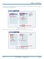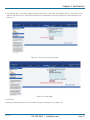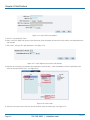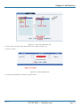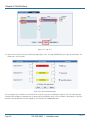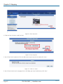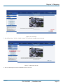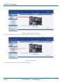
1
EME144A-R2 ServSensor V4E Lite Use this intelligent environmental monitoring BLACK device to identify problems before theyBOX disrupt your equipment. ® Features an embedded Web server and Linux operating system. Customer Support Information EME144A-R2 Order toll-free in the U.S.: Call 877-877-BBOX (outside U.S. call 724-746-5500) • FREE technical support 24 hours a day, 7 days a week: Call 724-746-5500 or fax 724-746-0746 • Mailing address: Black Box Corporation, 1000 Park Drive, Lawrence, PA 15055-1018 • Web site: www.blackbox.com • E-mail: [email protected] Trademarks Used in this Manual Trademarks Used in this Manual Black Box and the Double Diamond logo are registered trademarks of BB Technologies, Inc. Bluetooth is a registered trademark of Bluetooth Sig, Inc. Unicenter is a registered trademark of Computer Associates Think, Inc. SiteScope is a registered trademark of Freshwater Software, Inc. HP and OpenView are registered trademarks of Hewlett-Packard Company. IBM and Tivoli are registered trademarks of International Business Machines Corporation. WhatsUp is a registered trademark of Ipswitch, Inc. Linux is a registered trademark of Linus Torvalds. MS-DOS is a registered trademark of Microsoft Corporation. Denika and WebNM are registered trademarks of Plixer International, Inc. Big Brother is a registered trademark of Quest Software, Inc. MRTG is a registered trademark of Rand Investments, Inc. Modbus is a registered trademark of Schneider Automation, Inc. Somix is a registered trademark of Somix Technologies, Inc. Any other trademarks mentioned in this manual are acknowledged to be the property of the trademark owners. We‘re here to help! If you have any questions about your application or our products, contact Black Box Tech Support at 724-746-5500 or go to blackbox.com and click on “Talk to Black Box.” You’ll be live with one of our technical experts in less than 30 seconds. Page 2 724-746-5500 | blackbox.com EME144A-R2 FCC and IC RFI Statements Federal Communications Commission and Industry Canada Radio Frequency Interference Statements This equipment generates, uses, and can radiate radio-frequency energy, and if not installed and used properly, that is, in strict accordance with the manufacturer’s instructions, may cause interference to radio communication. It has been tested and found to comply with the limits for a Class A computing device in accordance with the specifications in Subpart B of Part 15 of FCC rules, which are designed to provide reasonable protection against such interference when the equipment is operated in a commercial environment. Operation of this equipment in a residential area is likely to cause interference, in which case the user at his own expense will be required to take whatever measures may be necessary to correct the interference. Changes or modifications not expressly approved by the party responsible for compliance could void the user’s authority to operate the equipment. This digital apparatus does not exceed the Class A limits for radio noise emission from digital apparatus set out in the Radio Interference Regulation of Industry Canada. Le présent appareil numérique n’émet pas de bruits radioélectriques dépassant les limites applicables aux appareils numériques de la classe A prescrites dans le Règlement sur le brouillage radioélectrique publié par Industrie Canada. EME144A-R2 724-746-5500 | blackbox.com Page 3 NOM Statement Instrucciones de Seguridad (Normas Oficiales Mexicanas Electrical Safety Statement) 1. Todas las instrucciones de seguridad y operación deberán ser leídas antes de que el aparato eléctrico sea operado. 2. Las instrucciones de seguridad y operación deberán ser guardadas para referencia futura. 3. Todas las advertencias en el aparato eléctrico y en sus instrucciones de operación deben ser respetadas. 4. Todas las instrucciones de operación y uso deben ser seguidas. 5. El aparato eléctrico no deberá ser usado cerca del agua—por ejemplo, cerca de la tina de baño, lavabo, sótano mojado o cerca de una alberca, etc. 6. El aparato eléctrico debe ser usado únicamente con carritos o pedestales que sean recomendados por el fabricante. 7. El aparato eléctrico debe ser montado a la pared o al techo sólo como sea recomendado por el fabricante. 8. Servicio—El usuario no debe intentar dar servicio al equipo eléctrico más allá a lo descrito en las instrucciones de operación. Todo otro servicio deberá ser referido a personal de servicio calificado. 9. El aparato eléctrico debe ser situado de tal manera que su posición no interfiera su uso. La colocación del aparato eléctrico sobre una cama, sofá, alfombra o superficie similar puede bloquea la ventilación, no se debe colocar en libreros o gabinetes que impidan el flujo de aire por los orificios de ventilación. 10. El equipo eléctrico deber ser situado fuera del alcance de fuentes de calor como radiadores, registros de calor, estufas u otros aparatos (incluyendo amplificadores) que producen calor. 11. El aparato eléctrico deberá ser connectado a una fuente de poder sólo del tipo descrito en el instructivo de operación, o como se indique en el aparato. 12. Precaución debe ser tomada de tal manera que la tierra fisica y la polarización del equipo no sea eliminada. 13. Los cables de la fuente de poder deben ser guiados de tal manera que no sean pisados ni pellizcados por objetos colocados sobre o contra ellos, poniendo particular atención a los contactos y receptáculos donde salen del aparato. 14. El equipo eléctrico debe ser limpiado únicamente de acuerdo a las recomendaciones del fabricante. 15. En caso de existir, una antena externa deberá ser localizada lejos de las lineas de energia. 16. El cable de corriente deberá ser desconectado del cuando el equipo no sea usado por un largo periodo de tiempo. 17. Cuidado debe ser tomado de tal manera que objectos liquidos no sean derramados sobre la cubierta u orificios de ventilación. 18. Servicio por personal calificado deberá ser provisto cuando: A: El cable de poder o el contacto ha sido dañado; u B: Objectos han caído o líquido ha sido derramado dentro del aparato; o C: El aparato ha sido expuesto a la lluvia; o D: El aparato parece no operar normalmente o muestra un cambio en su desempeño; o E: El aparato ha sido tirado o su cubierta ha sido dañada. Page 4 724-746-5500 | blackbox.com EME144A-R2 Table of Contents Table of Contents 1. Specifications........................................................................................................................................................................................... 6 2. Overview ............................................................................................................................................................................................. 7 2.1 Introduction..................................................................................................................................................................................... 7 2.2 What‘s Included............................................................................................................................................................................... 7 2.3 Hardware Description...................................................................................................................................................................... 8 2.3.1 Front Panel............................................................................................................................................................................ 8 2.3.2 Back Panel............................................................................................................................................................................. 9 3. Installation ............................................................................................................................................................................................10 3.1 Setting the IP Address.....................................................................................................................................................................10 3.2 Testing the New IP Address with the “Ping” Command..................................................................................................................12 3.3 Firmware Upgrade..........................................................................................................................................................................14 3.4 Multiusers and Groups Setup..........................................................................................................................................................17 3.4.1 Group Setup........................................................................................................................................................................17 3.4.2 User Setup...........................................................................................................................................................................19 3.5 Services and Security......................................................................................................................................................................21 3.5.1 Active Services Application (Disabling).................................................................................................................................21 3.5.2 Closing or Changing Ports Disabling HTTP and Enabling HTTPS........................................................................................... 22 3.5.3 The SNMPv3 SSL Security Feature........................................................................................................................................ 23 3.5.4 Active Security.................................................................................................................................................................... 24 3.5.5 The NAC or Network Access Control Security Feature......................................................................................................... 25 3.6 Setting Up a Sensor....................................................................................................................................................................... 25 3.6.1 Notification Thresholds........................................................................................................................................................ 27 3.6.2 Advanced Sensor Settings................................................................................................................................................... 29 3.7 Using an Internal Mic as a Sound Detection Sensor........................................................................................................................ 37 3.8 Expansion Ports............................................................................................................................................................................. 40 4. Notifications........................................................................................................................................................................................... 43 4.1 Adding a Notification..................................................................................................................................................................... 43 4.2 SNMP Trap..................................................................................................................................................................................... 44 4.3 E-mail........................................................................................................................................................................................... 48 4.4 SMS Notification............................................................................................................................................................................ 53 5. Mapping ........................................................................................................................................................................................... 59 5.1 Adding a Map............................................................................................................................................................................... 59 5.2 Monitoring via the Map Interface................................................................................................................................................... 63 6. Filters ........................................................................................................................................................................................... 64 6.1 Sensor Filters................................................................................................................................................................................. 64 6.2 Syslog Filters.................................................................................................................................................................................. 66 7. Making the ServSensor Visible to the Internet........................................................................................................................................ 69 8. Frequently Asked Questions (FAQs)........................................................................................................................................................ 70 EME144A-R2 724-746-5500 | blackbox.com Page 5 Chapter 1: Specifications 1. Specifications Audio — Sampling rate: 8 kHz Certifications — AdRem NetCrunch, Quest Software–Big Brother®, Castle Rock, HP® OpenView®, IBM® Tivoli®, LoriotPro, Logalot, MRTG®, SiteScope®, Somix®—WebNM® and Denika®, WhatsUp® Gold, Computer Associates Unicenter® TNG Components — Manufactured using highly integrated, low-power surface-mount technology to ensure long-term reliability Configuration — Via Web browser (HTTP/HTTPS) Expandable Modules — EME1X8: 8-port intelligent sensors module; EME1DC16: 16-port dry-contacts modules Mean Time Between Failures (MTBF) — 400,000 hours Memory — 128 MB SDRAM, 128 MB NVRAM Network Interface — (1) 10/100BASE-T Ethernet RJ-45 Operating System — Embedded Linux Processor — iMX25 CPU Protocols Supported (Client) — DHCP, DNS, SMTP, (5) NTP, SNMP Connectors — Inputs: (8) RJ-45 for connecting sensors; (2) RJ-45 expansion ports; (1) USB Version 1.1 Type A; (1) 2.5" jack for analog audio; (1) RS-485 2-pin terminal box (used for Modbus®); Output: (1) 2.5" jack for analog audio; (1) 2.5" jack for microphone Temperature Tolerance — Operating: 32 to 131° F (0 to +55° C) Humidity — 20 to 80%, noncondensing Altitude — 0 to 9842 ft. (0 to 300 m) Indicators — (19) LEDs: (1) Power, (1) Link, (1) Activity, (8) Status, (8) On-line Power — Input: 100–240 VAC, 47-63 Hz external power supply; Output: 7.0–9 VDC, 3 amps; Consumption: 5.025 watts, 0.670 amps Size — 1.8"H x 8.5"W x 5.4"D (4.6 x 21.6 x 13.7 cm) Weight — 1.7 lb. (0.8 kg) Page 6 724-746-5500 | blackbox.com EME144A-R2 Chapter 2: Overview 2. Overview 2.1 Introduction Used for environmental monitoring, the ServSensor V4E Lite identifies problems before they lead to business disruptions. This high-speed, accurate, intelligent monitoring device features a completely embedded host and Linux® operating system. 2.2 What’s Included Your package should contain the following items. If anything is missing or damaged, contact Black Box Technical Support at 724-746-5500. • (1) ServSensor V4E Lite unit • (1) 5-ft. crossover cable • (1) 5-ft. straight-pinned cable • (2) rackmounting brackets • (1) power adapter • (1) power cord • (1) temperature/humidity sensor (EME1TH2-005) with RJ-45 to RJ-45 cable • (4) terminal blocks (installed) • (1) CD-ROM containing this user’s manual and Help files EME144A-R2 724-746-5500 | blackbox.com Page 7 Chapter 2: Overview 2.3 Hardware Description Figure 2-1 illustrates the ServSensor’s front panel. Table 2-1 describes its components. 2.3.1 Front Panel 4 3 1 2 6 7 5 Figure 2-1. Front panel. Table 2-1. Front-panel components. Number Component Description 1 Power LEDWhen the unit is powered on, the power LED will be lit continuously. If the power LED is flashing, there is a problem with the CPU. Contact Technical Support at 724-746-5500 or [email protected]. 2 Link LEDThe Link LED indicates network connectivity. It lights when a network is connected to the ServSensor V4E Lite. 3 MicThe mic is a small hole for access to the internal microphone. Use it as a sound sensor (or use an external mic). 4 SD card slot 5 Activity LEDThe Activity LED flashes when network traffic is sent to or received by the ServSensor V4E Lite. 6 Status/Online LEDs 1–8The Status/Online LEDs are numbered 1–8. They indicate the connectivity status of the sensors connected to each port. You can also use these LEDs to indicate system status during various operations. SD card (not included) installs here. Additionally, the LEDs can indicate the progress of an upgrade. The red LEDs move from left to right to indicate activity, and all the green LEDs indicate overall progress of the upgrade. When all the red lights are off and the green are on, the upgrade/recovery process is complete. These lights also indicate if the unit is operating in safe mode. This is when the unit loads the operating system (OS) with a minimal set of drivers. If your device enters safe mode after rebooting, contact Black Box Technical Support at 724-746-5500 or [email protected]. The unit may enter recovery mode if a firmware upgrade is incomplete. In this case, the unit displays a continuously lit row of red LEDs. If this happens, contact Black Box Technical Support at 724-746-5500 or [email protected]. Page 8 724-746-5500 | blackbox.com EME144A-R2 Chapter 2: Overview Table 2-1 (Continued) . Front panel components. Number Component Description 7 Expansion ports E1–E2Use the two expansion ports numbered E1–E2 to connect the 8-port expansion module (EME1X8) and/or the 16 dry-contact expansion module (EME1DC16). 2.3.2 Back Panel Figure 2-2 shows the ServSensor’s back panel. Table 2-2 describes its components. 10 11 12 13 14 15 8 16 17 9 Figure 2-2. Back panel. Table 2-2. Back panel components. Number Component 8 (8) RJ-45 connectors 9 Barrel connector 10 Mic out connector Connect an external microphone for voice modem applications. 11 Audio in Connect an external microphone. 12 Audio out Connect the output for external speakers. 13 USB Type A portUse the USB 1.1 port to connect a USB GBarPRS/GSM compatible modem, a USB Wi-Fi dongle, or a USB Bluetooth® dongle. 14 2-pin terminal block (RS-485 port)The ServSensor V4E Lite supports Modbus master or slave. 15 RJ-45 10/100 network port Use this RJ-45 port to connect your ServSensor V4E Lite to the network. 16 Reset Press this button to reset the ServSensor V4E Lite. 17 EXT GND Use the EXT. GND connector to externally ground the unit. EME144A-R2 Description Use these ports to connect Intelligent Sensors to the ServSensor V4E Lite. This is a 7.5V DC plug. Connect a 7.0–9.0-V, 2.5-A power supply (included). 724-746-5500 | blackbox.com Page 9 Chapter 3: Installation 3. Installation 3.1 Setting Up the IP Address The ServSensor V4E Lite is shipped with the default IP address of 192.168.0.100. Follow the steps listed below to change this IP address to fit your own network configuration. Before starting, make sure you have these items: • (1) RJ-45 male CAT5 crossover cable • (1) PC with Ethernet card or LAN socket • (1) Power socket for the unit to connect to To set up the IP address: 1. Connect the ServSensor V4E Lite via its Ethernet port to your computer’s Ethernet port with a CAT5 crossover cable. 2. Open a Web browser and type the default IP address (as in Figure 3-1), then press the Enter key. Figure 3-1. Google Web Browser screen. NOTE: In some cases, your computer might not be able to connect to this default IP address. In this situation, you will need to change the IP address of your PC. See the instructions above. 3. After you press the Enter key in Step 2, Figure 3-2 appears. The default password for Admin is “public.” Change the password to make your unit secure. Page 10 724-746-5500 | blackbox.com EME144A-R2 Chapter 3: Installation Figure 3-2. User Type/Password screen. 4. Next, the home page will be displayed. It looks similar to the screen shown in Figure 3-3. Figure 3-3. Settings tab. 5. Click on the “Settings” tab, then click on “Ethernet network” from the list on the left frame of the page. See Figure 3-4. EME144A-R2 724-746-5500 | blackbox.com Page 11 Chapter 3: Installation Figure 3-4. Ethernet Network screen. To change the IP address of the ServSensor V4E Lite: 1. Select Ethernet network. 2. Input the new IP address. 3. Click the “Save” button. 3.2 Testing the New IP Address with the “Ping” Command Once you assign the new IP address, use the “ping” command to test the ServSensor V4E Lite. You can also use this command as a diagnostic tool to check whether your unit is connected to the network. See Figure 3-5. 1. Click “Start.” 2. Click “Run.” 3. Type “ping (IP address that the user entered),” and press Enter. An example IP address (10.1.5.206) is shown in Figure 3-5. Page 12 724-746-5500 | blackbox.com EME144A-R2 Chapter 3: Installation Figure 3-5. Ping Command screen. 4. After you press the “Enter” key, an MS-DOS® prompt window showing the test results appears (see Figure 3-6). If you get a message saying “request timed out,” either the IP address is incorrect or a ServSensor V4E Lite is not connected to the network. Figure 3-6. MS-DOS window. EME144A-R2 724-746-5500 | blackbox.com Page 13 Chapter 3: Installation 3.3 Firmware Upgrade Make sure you are running the latest firmware. Please contact Black Box Technical Support at 724-746-5500 or [email protected] for the latest firmware. NOTE: This manual refers to the Default IP address, 192.168.0.100. Substitute this for your own IP address if you have changed the default IP address. This tutorial gives you the information you need to upgrade the firmware. To get to the tutorial’s starting point: • Log in as administrator. • Click the “Settings” tab. Figure 3-7. Settings tab. Page 14 724-746-5500 | blackbox.com EME144A-R2 Chapter 3: Installation Figure 3-8. System Administrator, System Maintenance screen. 1. Click “System Administrator” and then “System Maintenance.” 2. Click “Upgrade.” 3. The popup screen shown in Figure 3-9 appears. Figure 3-9. Reboot prompt. 4. Click “OK.” The unit will reboot in Safe Mode. Then you will be redirected to the Safe Mode Web-based interface. This can take some time, so please be patient. The page will display the message shown in Figure 3-10 when rebooting. Figure 3-10. Firmware Upgrade Rebooting screen. EME144A-R2 724-746-5500 | blackbox.com Page 15 Chapter 3: Installation 5. After the ServSensor reboots, the page shown in Figure 3-11 appears. Click “Browse” and navigate to the firmware file you downloaded, then click “Upgrade.” Figure 3-11. Upgrade button. 6. During the process, you will see the messages shown in Figure 3-12. Figure 3-12. Upgrade Status screen. 7. The unit will then reboot. The process is complete when the LEDs are back to their “normal” status. Page 16 724-746-5500 | blackbox.com EME144A-R2 Chapter 3: Installation 3.4 Multi-users and Groups Setup 3.4.1 Group Setup 1. Log in to the ServSensor V4E Lite with the Administrator password. The default will be “public” if you have not changed this yet. 2. Click on the Settings page, then System Adminstrator, then User & Group Management as shown in Figure 3-13. NOTE: The following screen diagrams may appear small and hard to read. Please use the zoom feature in your PDF reader program to increase the size of the page to better view these screen diagrams. Figure 3-13. Group Setup screen. 3. Click on the “Go to Group Setup” link that will take you to the Groups page shown in Figure 3-14. Figure 3-14. Groups page. EME144A-R2 724-746-5500 | blackbox.com Page 17 Chapter 3: Installation 4. Click on the “Add” button to add your groups as shown in Figure 3-14. Figure 3-15. User & Group Management screen. 5. Enter your group name. For example, we have added a group called “System Guest” and entered our description. 6. Check the objects with the Web interface that this group will be able to Modify and View. Then, click the “Finish” button to save your group. (See Figure 3-15.) Figure 3-16. System Guest group added. 7. The new group “System Guest” has been added to our group list as shown in Figure 3-16. Page 18 724-746-5500 | blackbox.com EME144A-R2 Chapter 3: Installation Figure 3-17. User & Group Management screen. 8. If you want to modify your group settings, click on the group you want to modify. Then click on the “Properties” button as shown in Figure 3-17. 3.4.2 User Setup 1. Click on the “Users” tab and then click the “Add” button to add the new users to your groups as shown in Figure 3-18. Figure 3-18. User Setup screen. EME144A-R2 724-746-5500 | blackbox.com Page 19 Chapter 3: Installation 2. Enter your user details as shown in Figure 3-19. In our example, we have entered Bob Smith as your Guest into our “System Guest” group. We have also added the option so that this user cannot change his login password. After adding your users for each group, click the “Finish” button to save each user. Figure 3-19. Enter user details. 3. The new user has been entered into our list of users. Figure 3-20. User list. 4. To modify a user’s setting, click on the user to select it, then click the “Properities” button as shown in Figure 3-21. Page 20 724-746-5500 | blackbox.com EME144A-R2 Chapter 3: Installation FIgure 3-21. Properties button. 3.5 Services and Security 3.5.1 Active Services Application (Disabling) Figure 3-22. Services and Security screen. You can enable or disable the Nagios, Secure Shell, and Telnet applications running on the unit to make it more secure. EME144A-R2 724-746-5500 | blackbox.com Page 21 Chapter 3: Installation 3.5.2 Closing or Changing Ports Disabling HTTP and Enabling HTTPS Figure 3-23. Active services. You can also close or change the ports used to access the unit’s Web interface, disable HTTP, and enable HTTPS only. The “s” at the conclusion of HTTPS stands for secure. The SSL/TLS connection type is used primarily for high-value sites or “pages,” to make it more likely to be unreadable to someone at the end points. The traffic between client and the ServSensor V4E Lite is not cached along the various units as it moves across the Internet, so it can’t be accessed by someone after the connection is terminated. Page 22 724-746-5500 | blackbox.com EME144A-R2 Chapter 3: Installation 3.5.3 The SNMPv3 SSL Security Feature Figure 3-24. Add Key screen. Use the SNMPv3 SSL (Secure Sockets Layer), which is the standard security technology for establishing the encrypted link betwen the ServSensor and the Web browser. The link ensures that all data passed between the ServSensor and the browser remains private and integral. SNMPv3 provides important security features: • Confidentiality—Encrypts packets to prevent snooping by an unauthorized source. • Integrity—Message integrity to ensure that a packet has not been tampered with in transmit. • Authentication—To verify that the message is from a valid source. EME144A-R2 724-746-5500 | blackbox.com Page 23 Chapter 3: Installation Figure 3-25. Select SSL Key screen. 3.5.4 Active Security In the active security section, you can enable users who are logged into the unit’s Web interface to “Acknowledge” alarms, which is normally reserved only for the Administrator. When the unit boots up, it will announce the IP address that it has been configured with. As an added security feature, this announcement can be disabled so that the IP address remains unknown. Figure 3-26. Active Security screen. Page 24 724-746-5500 | blackbox.com EME144A-R2 Chapter 3: Installation 3.5.5 The NAC or Network Access Control Security Feature Figure 3-27. Network Access Control screen. The NAC or Network Access Control feature enables you to restrict access to the Web interface for only certain IP addresses, or deny access to the Web interface for only certain IP addresses. 3.6 Setting Up a Sensor This section describes the basic setup of a sensor, using a Black Box temperature sensor as an example. If you require information on specific functions of a particular sensor, then download the manual for that sensor from our Web site, www.blackbox.com. 1. Plug the sensor into one of the RJ-45 “intelligent sensor ports” on the ServSensor’s rear panel. In this example, we will use Port 1. See Figure 3-28. Figure 3-28. Intelligent sensor Port 1. 2. Point your browser to the ServSensor’s IP address (the default is 192.168.0.100). Log in as the administrator using your administrator password (the default is “public”). You will then be taken to the summary page shown in Figure 3-29. EME144A-R2 724-746-5500 | blackbox.com Page 25 Chapter 3: Installation Figure 3-29. Summary page. The temperature sensor should be listed, along with its current reading and status. This summary page enables you to quickly see which sensors are connected and their status, view the system log, and also view footage from any connected cameras. Next are some of the tools the Web-based interface provides for getting feedback from the sensors. 3. Click on the temperature sensor’s name (indicated in Figure 3-29). This will bring you to Figure 3-30, the Sensors page. Page 26 724-746-5500 | blackbox.com EME144A-R2 Chapter 3: Installation Figure 3-30. Sensors page. NOTE: Another way to access this page is to click on the “Sensors” tab at the top of the page. 3.6.1 Notification Thresholds From this page, you can carry out various operations as indicated above. You can also view the current status (normal, low critical, high critical, etc). In Figure 3-30, the sensor indicates a temperature of 27° C and a status of Normal. If you click on the blue marker arrow next to the “Threshold adjustment” label (shown in Figure 3-30), you can drag this marker to re-configure the thresholds. After dragging the marker, click “Save.” In Figure 3-31, you can see that this marker has been moved to make a new threshold, and the sensor status has changed along with it. Figure 3-31. High critical status shown. EME144A-R2 724-746-5500 | blackbox.com Page 27 Chapter 3: Installation If the marker is then dragged back above the current temperature reading, the status should return to a normal condition again. (See Figure 3-32.) NOTE: If this does not happen right away, press the browser’s refresh button. Figure 3-32. Normal status indicated. If you want to take a sensor offline, then click on the “Sensor Currently” button. This will place the sensor offline and you won’t have to physically unplug it. See Figure 3-33. Figure 3-33. Sensor Online/Offline screen. Your page will look similar to Figure 3-34 after you take the sensor offline. Figure 3-34. Sensor Offline screen. Page 28 724-746-5500 | blackbox.com EME144A-R2 Chapter 3: Installation To bring a sensor back online, select the type from the drop-down menu and click “Save.” See Figure 3-35. Figure 3-35. Select Sensor Type screen. 3.6.2 Advanced Sensor Settings Click on the Advanced Settings tab to get the options shown in Figure 3-36. Figure 3-36. Advanced Sensor Settings screen. EME144A-R2 724-746-5500 | blackbox.com Page 29 Chapter 3: Installation Advanced Mode Functions: FIgure 3-37. Advanced mode functions, units. Units: Changes units from C to F or vice versa. Figure 3-38. Advanced mode functions, rearm. Rearm: The Rearm parameter is useful for sensors, such as the temperature and humidity sensors, whose values can vary. This prevents the sensor from flickering between two states. For example, if the Warning High threshold for the temperature sensor is set to 80 degrees, and the sensor temperature varies between 79 and 80, you could be faced with a very large number of e-mails, traps, and events logged. The Rearm parameter prevents this by forcing the temperature to drop by the Rearm value before changing the state back to normal. In this example, if Rearm is set to 2, then the sensor would have to drop from 80 down to 77 before the status would change from Warning High back to normal. Page 30 724-746-5500 | blackbox.com EME144A-R2 Chapter 3: Installation Figure 3-39. Advanced setings, reading offset. Reading offset: A calibration tool. If you want to calibrate the temperature sensor, for example, you could enter an offset value of 5. This means that if the sensor reads 20 degrees then it would record as 25 degrees. This figure can also be a minus figure (for example, -5 would show 15 degrees instead of 20). Figure 3-40. Advanced settings, data collection type. EME144A-R2 724-746-5500 | blackbox.com Page 31 Chapter 3: Installation Data Collection Type This refers to the data collection from the sensor and how the data is then displayed on the graphs. There are three options for collection of data: Average, Highest, and Lowest. The default setting is “Average.” When the data collection type is set to “Average,” the output graphs for the daily, monthy, and yearly all have the same size on the screen. For the daily graph, each data point on the graph is one data point collected from the sensor. But for the monthly and yearly graph, to display more data into the same size as for the daily graph, some consolidation on the data is needed. One data point on the monthly and yearly graph is the average of the sensor data in a range. The maximum and minimum values showing on the monthly and yearly graphs are the value of this consolidated data and not the raw data over that period of time. When the Data Collection Type is set to the highest setting,then you will get the graphing output dsiplaying the sensor‘s highest reading. This is the same for the lowest setting. Figure 3-41. Advanced settings, display style. Display Style You can keep the sensors “Dislplay Style” in the Web interface as the Basic Style (slide bar) or you can change it to “Gauge Style.” Page 32 724-746-5500 | blackbox.com EME144A-R2 Chapter 3: Installation Figure 3-42. Gauge Style screen. When switching to the Gauge Style type, you will first be prompted with the popup dialog box shown above. EME144A-R2 724-746-5500 | blackbox.com Page 33 Chapter 3: Installation Figure 3-43. Sensor threshold levels. You will now see the new display where you can set the sensor’s threshold levels as shown above. Page 34 724-746-5500 | blackbox.com EME144A-R2 Chapter 3: Installation Figure 3-44. Advanced Settings Text and Colors screen. After clicking on the “Advanced Settings” tab, you can change the text and colors for each sensor threshold as shown in the screen above. Figure 3-45. Advanced Settings, Check Rate of Change screen. EME144A-R2 724-746-5500 | blackbox.com Page 35 Chapter 3: Installation Check rate of change When enabling the “check rate of change” feature for the sensor, you can set the rate in a percentage ranging from 1% to 80% over a period of time ranging from 1 to 20 minutes. You can set the direction to Up, Down, or Both, and you can set the Status when the limit is exceeded to show either High Critical or Low Critical. You can tie this sensor alert to any notification. Use it with a fuel level sensor to alert you to theft of fuel or leaks in storage tanks. Continuous Time Settings and Minimum Time Settings Tabs The following advanced functions set the time frame in which the system should delay a notification being triggered when a sensor gives a reading that exceeds the thresholds (high warning, normal, etc). Continuous Time to Report High Critical: This helps to eliminate unnecessary messages during minor fluctuations. You can set the amount of time to delay a notification of a status change from high warning to high critical. Enter the time in seconds and press the “Save” button. The amount of time that you can enter is between 0 and 65535 seconds, which equals approximately 18 hours. Continuous Time to Report High Warning: As above, but delays notification for “High Warning.” Continuous Time to Report for Normal: As above, but delays notification for return to “Normal” state. Continuous Time to Report for Low Warning: As above, but delays notification for “Low Warning” state. Continuous Time to Report for Low Critical: As above, but delays notification for “Low Critical” state. Continuous Time to Report for Sensor Error: As above, but delays notification being sent for sensor going into an error state. Example: An airflow sensor or humidty sensor may have temporary drops in readings that are normal operating characteristics; a logical time limit is set to show abnormal conditions. Enable Calendar: If you select this option, the screen shown in Figure 3-46 will be displayed. Figure 3-46. Enable Calendar Status screen. Page 36 724-746-5500 | blackbox.com EME144A-R2 Chapter 3: Installation In this example, we want to monitor an office building between the hours of 7 PM–9 AM Monday–Friday only. You can see in this picture we have selected the “Do Not Report” option for the hours in which we do not want to receive any notifications or have any events logged. You change the status of that time frame (Report/Do Not Report) simply by clicking on the square. This will change it from blue to gray; a second click will return it to blue. Figure 3-47. Enable Calendar screen. 3.7 Using an Internal Mic as a Sound Detection Sensor You can use the internal microphone (or an external plugged into the line in jack) as a sound detector. This tutorial provides you with the information you need to set up the internal mic as a sound detection sensor. To get to the starting point of this tutorial: • Log into the Web based interface. • Click on the Sensors tab. 1. Click “Sound Detector” under the Sensors menu. See Figure 3-48. 2. Click “Advanced Mode.” 3. After you click on the Advanced Mode button, you’ll see the advanced options available. (See Figure 3-49.) EME144A-R2 724-746-5500 | blackbox.com Page 37 Chapter 3: Installation Figure 3-48. Sound Detector tab. Page 38 724-746-5500 | blackbox.com EME144A-R2 Chapter 3: Installation Figure 3-49. Advanced options. Recording Source: Here you can choose either internal or external microphone. Microphone Boost (+20 dB): Boosts the microphone by 20 dB. Microphone Sensitivity: The level of sensitivity that can be set. For example, if you set the level to 80, the microphone will detect more sound than if the level were set at 20. Pulse Length: This defines the minimum duration of a sound to trigger an alert notification. Rearm: The Rearm parameter prevents the sensor from flickering between two states. For example, if the Warning High threshold for the sound sensor is set to 80 and the sensor temperature varies between 79 and 80, a very large number of e-mails, traps, and events would be logged. The Rearm parameter prevents this by forcing the signal level to drop by the Rearm value before changing the state back to normal. In this example, if Rearm is set to 2. then the sensor would have to drop from 80 down to 77 before the status would change from Warning High back to normal. Data Collection Type: There are three settings for this parameter: lowest, highest, and average. Data will be collected for the lowest, highest, or average sound reading accordingly. Advanced Status Text and Color: Here you can select to change your display text and warning colors. EME144A-R2 724-746-5500 | blackbox.com Page 39 Chapter 3: Installation NOTE: As with all the other sensors, you can now set up the sound detector to be attached to a notification. Then, when your thresholds are broken, it will trigger a specified type of notification. 3.8 Expansion Ports The ServSensor has two expansion ports that enable you to connect up to two daisychainable expansion modules. The available expansion modules are an 8-port intelligent sensor board (EME1X8) and an opto-isolated (16) dry-contact expansion module (EME1DC16). In this section, we will go through the basic setup of the 8-port intelligent sensor board. If you need information on specific functions of a particular sensor or expansion board, then please refer to the relevant manual for that product. 1. Plug the expansion board into one of the two ports located on the front panel of the unit. These are numbered E1 and E2. See Figure 3-50. Figure 3-50. Plug expansion boards into these ports. 2. From the summary page, navigate to the “Sensors” tab. Then click “Extended port” as outlined in Figure 3-51. Figure 3-51. Sensors tab, extended port option. Page 40 724-746-5500 | blackbox.com EME144A-R2 Chapter 3: Installation 3. A list of all extended ports will be shown. Each port will display any available extension modules, which will be highlighted in green. Click on the module to go to the sensor settings page. Figure 3-52. Extended Port1 selection. 4. This will bring you to the Extended Port Sensors page (see Figure 3-53). Figure 3-53. Extended Port Sensors page. 5. Once you have clicked on the “Dual sensors” tab, you will be directed to the familiar-looking Notification Thresholds page (see Figure 3-54). From this page, you can carry out various operations as indicated in the sensor settings tutorials. EME144A-R2 724-746-5500 | blackbox.com Page 41 Chapter 3: Installation Figure 3-54. Notification Thresholds page. Page 42 724-746-5500 | blackbox.com EME144A-R2 Chapter 4: Notifications 4. Notifications If you set up a notification, you can define the action to take when the sensor gives a reading beyond your set thresholds. This enables you to determine how you will be notified that a sensor’s reading has reached the specified parameters (high warning, critical, etc.) described in Chapter 3. This tutorial provides you with the information you need to set up a notification. To get to the starting point of this tutorial: • Login as administrator. • Click the “Notifications” tab. 4.1 Adding a Notification 1. Click on the “Begin Notification Wizard” tab as shown in Figure 4-1. Figure 4-1. Notification Wizard tab. 2. The Notification Wizard page will be displayed as shown in Figure 4-2. EME144A-R2 724-746-5500 | blackbox.com Page 43 Chapter 4: Notifications Figure 4-2. Notification Wizard page. Next, you’ll see how to set up a few different ways of notification step by step. 4.2 SNMP Trap If you set up a notification via an SNMP trap, when your sensor reaches a certain threshold, it will send a notification to your SNMP server. This tutorial provides you with the information you need to set up an SNMP trap. To get to the tutorial’s starting point: • Log in as administrator. • Click the “Notifications” tab. • Choose “Notifications Wizard.” • Choose “SNMP Trap.” 1. After selecting to add an SNMP trap, you will need to fill in the following information shown in Figure 4-3. Figure 4-3. Add an SNMP trap. Page 44 724-746-5500 | blackbox.com EME144A-R2 Chapter 4: Notifications 2. Once this information is correct, click the “Add Trap Destination” button. Input another trap or click on “Next.” Enter the parameters shown in Figure 4-4. Figure 4-4. Notification parameters. These parameters set the maximum number of times to send the trap notification and the time interval between each notification. 3. After clicking “Next,” you’ll see the screens shown in Figures 4-5 and 4-6. Figure 4-5. Parameter Selection, screen #1. EME144A-R2 724-746-5500 | blackbox.com Page 45 Chapter 4: Notifications Figure 4-6. Parameter Selection, screen #2. On these screens, you can select the parameters for when to send the SNMP trap notification. In this example, we selected to bind the SNMP trap to the temperature sensor connected on Port 1. The trap will be sent when the sensor reads a “High Critical” and we bind this to the SNMP trap we just created and named “SNMP Trap 1.” 4. Once we have created the parameters for the SNMP trap, we need to make it active. To do this, go back to the “Notifications” tab. (It should look like the screen shown in Figure 4-7.) Click “Create.” Figure 4-7. Notifications tab. Page 46 724-746-5500 | blackbox.com EME144A-R2 Chapter 4: Notifications 5. Select the sensor and SNMP trap parameters (see Figures 4-8 and 4-9). First, click on the board that the sensor is attached to and then select the sensor and click “Next.” Figure 4-8. Select the sensor. 6. Select the status that you want to issue the notification for, select the action type, then click “Finish.” Figure 4-9. Select the SNMP parameters. EME144A-R2 724-746-5500 | blackbox.com Page 47 Chapter 4: Notifications 7. The SNMP trap has been added to the Notifications page. Figure 4-10. SNMP trap added. NOTE: To remove this trap and make it inactive, highlight the notification and click “Remove.” You can repeat this process to set up multiple SNMP traps for different sensors or for multiple SNMP servers, etc. 4.3 E-mail This tutorial provides you with the information needed to set up an e-mail notification. To get to the starting point of this tutorial: • Log in as administrator. • Select the “Notifications” tab. • Click “Notification Wizard.” 1. If you set up an e-mail notification, Figure 4-11 will appear. Click the “Action Name” field and choose a name for your e-mail. Click the “Mail From” and “Mail To” fields and enter the appropriate information, then click “Next.” Figure 4-11. E-mail Action Wizard screen. Page 48 724-746-5500 | blackbox.com EME144A-R2 Chapter 4: Notifications 2. After clicking “Next,” you will get a page where you can input the e-mail name and message. Click the “Customize” button, and the fields will re-write in a format that will allow for an automated e-mail that will display the sensor information. (See Figure 4-12.) Figure 4-12. Input e-mail name and message. Figure 4-13. Attach graph. 3. Click “Next.” 4. Now you need to input your SMTP server address for your e-mail account. (See FIgure 4-14.) EME144A-R2 724-746-5500 | blackbox.com Page 49 Chapter 4: Notifications Figure 4-14. Input SMTP server address. 5. Once this is entered, click “Next.” 6. Now, as with the SNMP trap, you can select how many times to attempt to resend the e-mail, and the time elapsed between each attempt. 7. Click “Next” after you fill in your parameters. (See Figure 4-15.) Figure 4-15. Select frequency to resend e-mail attempts. 8. Now link the e-mail you just created to the temperature sensor on Port 1. Select the board the sensor is attached to, then select the sensor and click “Next.” (See Figure 4-16.) Figure 4-16. Select sensor. 9. Select the status you want to issue the alert for and then select the action type. (See Figure 4-17.) Page 50 724-746-5500 | blackbox.com EME144A-R2 Chapter 4: Notifications Figure 4-17. Select status and action type. 10. Click “Finish.” You will now be taken back to screen shown in Figure 4-18. 11. Click on “Create.” Figure 4-18. Create notification link 12. Create the notification link as before. Then click “Next.” EME144A-R2 724-746-5500 | blackbox.com Page 51 Chapter 4: Notifications Figure 4-19. Create notification tab: select board, select termperature. Figure 4-20. Create notification tab: select status, select e-mail. 14. You will now be back at the main notification page. You should now see listed our two notifications, the SNMP trap and the e-mail. (See Figure 4-20.) As you can see from this page, an SNMP trap is set up to give us notification of a “High Critical,” and an e-mail notification that will activate on a “High Warning.” Page 52 724-746-5500 | blackbox.com EME144A-R2 Chapter 4: Notifications Figure 4-21. SNMP Trap and E-mail Notificiations screen. 4.4 SMS Notification Set up a notification so that you will be sent an SMS message. This message can be sent via a GSM/GPRS mobile phone connected via a Bluetooth connection or the USB port. This tutorial provides you with the information you need to set up a SMS notification. To get to the starting point of this tutorial: • Log in as administrator. • Select the “Notifications” tab. • Click “Notification Wizard.” 1. From the list of notification types, select SMS and click “Next.” You will then be presented with the screen shown in Figure 4-22. Select the “Action Name” field and enter a notification name. Then select the “Phone Number” field and enter the phone number you want to send the notification to. Click “Next.” 2. You can now either add multiple numbers, delete phone numbers, “Cancel” this action, or click “Next.” In this case, we will click “Next.” (See Figure 4-23.) Figure 4-22. SMS Action Wizard, screen #1. EME144A-R2 724-746-5500 | blackbox.com Page 53 Chapter 4: Notifications Figure 4-23. SMTP Action Wizard, screen #2. 3. Now we will set up the message that will be sent to the phone. You will see the screen shown in Figure 4-24. Click the “Customized” button to add a macro to your notification. Figure 4-24. Customize Macro screen. NOTE: A macro is a script that returns specific data collected by the unit. In our example, the macro will tell the notification to contain the “description” (sensor name), the value (current sensor reading), and the status (high/low warning, etc.). These macros are common to all sensor notifications. 4. You will now see that the SMS message has changed its format to include the Macro script. (See Figure 4-25.) Click “Next.” Page 54 724-746-5500 | blackbox.com EME144A-R2 Chapter 4: Notifications Figure 4-25. Macro script message. 5. Next, we will set up the type of connection. This will depend on the type of modem you are connecting. For the purpose of this tutorial, we will assume you are connecting a GSM/GPRS enabled modem to the serial port. Select COM1 from the list. (See Figure 4-26.) 6. Choose the port that the modem is connected to. Figure 4-26. Choose the Connection Type You Wish to Use screen. 7. You will now be able to select the number of times you want the SMS to be resent and the interval between sending them. (See Figure 4-27.) 8. Select the number of times you want to resend this notification and the interval (in seconds). Click “Next.” EME144A-R2 724-746-5500 | blackbox.com Page 55 Chapter 4: Notifications Figure 4-27. Select number of times to resend and intervals. 9. Select the sensor that you want to bind this notification to. 10. Choose the board and sensor, then click “Next.” Figure 4-28. Choose board and sensor. Page 56 724-746-5500 | blackbox.com EME144A-R2 Chapter 4: Notifications Figure 4-29. Link sensor to action tab. 11. This time we will use this notification for a low warning. Then select the notification name we assigned, in this case we chose “SMS 1.” Click “Finish” to finalize this. (See Figure 4-29.) 12. Now we will add the SMS notification to our active list. This is the same process as for the others—simply click on “Create” and then select the appropriate parameters. Follow Steps A–F below and on the next page. A. Select the board the sensor is connected to. B. Select the sensor. C. Click “Next.” Figure 4-30. Steps A–C. D. Select the status you want to issue the alert for. E. Select the action type. F. Click “Finish.” EME144A-R2 724-746-5500 | blackbox.com Page 57 Chapter 4: Notifications Figure 4-31. Steps D–F. 13. You will now be back at the main notification page (Figure 4-32). The page should display three types of notifications: the SNMP trap, e-mail, and SMS. Figure 4-32. Main notification page. For the purposes of this tutorial, we will not cover the setup of every type of notification. However, with this information you should be able to follow the procedure for the other types of notifications easily, as they all follow a similar format. If you have questions, contact Black Box Technical Support at 724-746-5500 or [email protected]. Page 58 724-746-5500 | blackbox.com EME144A-R2 Chapter 5: Mapping 5. Mapping The mapping feature allows instant visual feedback about a sensor’s position and status. It is a useful monitoring tool for a setup with several sensors in different positions. This tutorial provides you with the information needed to set up the mapping feature. To get to the starting point of this tutorial: • Log in as administrator. • Click the “Map” tab. 5.1 Adding a Map 1. First, we need to add a picture file to be used as the map. This can be a blueprint of your office, a 3D picture of your office/site being monitored, or a photo of the wiring closet you are monitoring. NOTE: The maximum map file size is 512 KB. Figure 5-1. Click on the “Map” tab. 2. Browse to the file on your hard drive that you want to use. Figure 5-2. Browse to selected file. 3. In this tutorial, we are going to use a 3D map of a town center we are monitoring. EME144A-R2 724-746-5500 | blackbox.com Page 59 Chapter 5: Mapping Figure 5-3. Enter map name. 4. Choose to have the map as a top-level map. Figure 5-4. Enter map level. 5. You will now have the option to finish or to add sensors to your map. For this tutorial, click “Next.” Figure 5-5. “Finish” or “Next.” 6. You will now be taken to the map page where it will display your map. To add sensors, click “Next.” Page 60 724-746-5500 | blackbox.com EME144A-R2 Chapter 5: Mapping Figure 5-6. Sensor map. 7. After clicking “Next,” click the “Unlock” button. This enables you to add sensors to the map. Figure 5-7. Add sensors to map. 8. You can now drag sensor icons and position them on the map. EME144A-R2 724-746-5500 | blackbox.com Page 61 Chapter 5: Mapping Figure 5-8. Position sensor icons on map. 9. After you have positioned the sensors in the correct location of your map, click “Lock.” Figure 5-9. Click “Lock.” 10. Finally you click on the “Finish” button to save your changes. Page 62 724-746-5500 | blackbox.com EME144A-R2 Chapter 5: Mapping Figure 5-10. Save changes. 5.2 Monitoring via the Map Interface Now we are going to look at how to monitor the sensor status and use the map interface. 1. To see further information about a sensor, you can click on its icon. First, you must click on the “Unlock Icons” button. Figure 5-11. Using the map interface. If you connect other sensors, these too can be dragged and positioned on the map. EME144A-R2 724-746-5500 | blackbox.com Page 63 Chapter 6: Filters 6. Filters 6.1 Sensor Filters 1. The ServSensor comes equipped with the option to filter your sensor information that is displayed within the summary page. To enter the filter menu, select “Sensor Filters” from the drop-down tab on the left side of the page. Figure 6-1. Select sensor filters. 2. Once you click the tab, you will be able to select your filter results by altering various fields of information contained within the sensor filter window. Figure 6-2. Add information fields. Page 64 724-746-5500 | blackbox.com EME144A-R2 Chapter 6: Filters 3. You can alter the page reload interval by using these options. Figure 6-3. Alter the page reload interval. 4. Once you have selected your preferred filter options, your new settings will be displayed in the “Sensor Information” window found on the Summary page. Figure 6-4. Summary page. EME144A-R2 724-746-5500 | blackbox.com Page 65 Chapter 6: Filters 6.2 Syslog Filters Syslog filters enable you to customize your syslog window. To begin. select the “Syslog Filters” tab found on the summary page. Figure 6-5. Syslog Filters tab. Once you click the tab, you will be able to select your filter results by altering various fields of information contained within the syslog filter window. Figure 6-6. Drop-down menu. By checking and unchecking various boxes within the Syslog filter window, you can customize your displayed results contained within the syslog filter. Page 66 724-746-5500 | blackbox.com EME144A-R2 Chapter 6: Filters Figure 6-7. Customize syslog filter results display. You can alter your reload interval by using the options shown below. Figure 6-8. Change reload interval. Once you have selected your preferred filter options, your new settings will be displayed in the “System log Information” window found on the Summary page. EME144A-R2 724-746-5500 | blackbox.com Page 67 Chapter 6: Filters Figure 6-9. Saved syslog filters display. Page 68 724-746-5500 | blackbox.com EME144A-R2 Chapter 7: Making the ServSensor Visible on the Internet 7. Making the ServSensor Visible on the Internet The setup we have just created will enable you to access your ServSensor V4E Lite on a local area network (LAN), monitor via the Web based interface, or with SNMP traps. But, what if you want to be able to remotely access your unit from anywhere in the world? This is possible; however, the following steps are only a guide. Your exact setup and configuration will often depend on your network equipment. You are going to need access to your router, if you are using one, and know whether your IP address is static or dynamic. 1. Suppose your ServSensor is connected to a router on your network, and the following IP addresses are assigned: Your unit’s IP address is the default 192.168.0.100. Your computer’s IP address is 192.168.0.200 Your router’s IP address is 192.168.0.300 2. To find out your router’s external IP address, go to www.whatsmyip.com Suppose your router’s external IP address is 278.67.04.09 3. You now need to set up port forwarding on your router. This varies depending on your router’s model. Generally, you need to point your browser to your router”s IP address (in this case 192.168.0.300). This will then enable you to log into your router’s administration interface. You can find how to go about doing this for your router on www.portforward.com For an example of how to do this for a commonly used router, follow this link :-http://www.portforward.com/english/routers/ port_forwarding/Linksys/WRT54G/HTTP.htm You need to set up your router’s HTTP forwarding to Port 80. This will then mean when you access your router using the external IP address, you will be forwarded to your unit’s internal IP address. 4. To test this, open your Web browser, and go to your external IP address (in our example 278.67.04.09). If you’re using a dynamic IP address, check it again before doing this because it may have changed since the start of this tutorial. 5. To make this easier, you could use a Dynamic Name Server (DNS). This means that you no longer need to remember IP addresses or use www.whatsmyip.com to find out your IP address. You will instead register a domain name (for example mysensorProbe2.homeip.com). This will then automatically point to your router’s external IP address (e.g. 278.67.04.09). This will require you to register the domain name and open an account with a DNS service provider. We recommend www.dyndns.com because it allows you to register up to five free domain names. 6. If you have set up everything correctly, you will now be able to access your unit from anywhere in the world simply by pointing your Web browser to your DNS address. EME144A-R2 724-746-5500 | blackbox.com Page 69 Chapter 8: Frequently Asked Questions (FAQs) 8. Frequently Asked Questions (FAQs) Question: I cannot see the temperature sensor displayed on summary page. Answer: After logging in for the first time with the temperature sensor connected, you may need to do the following. Figure 8-1. Select sensor to display. Next, click on “Apply Filter.” The temperature sensor should then be displayed in the list of connected sensors. Question: I cannot access my unit’s Web interface. If you’re having issues with network connectivity, first make sure that the link100 LED is lit on the front display of the unit. If this is not lit, then no network connection is present. Answer: 1. If connected directly to a PC, make sure you’re using a good quality crossover cable. 2. Make sure you’re using a standard CAT5 Ethernet cable to connect to your network. Page 70 724-746-5500 | blackbox.com EME144A-R2 Chapter 8: Frequently Asked Questions (FAQs) Question: What do my LED lights mean? Answer: The following diagrams show what the various LED displays mean. Figure 8-2. LED patterns in Normal mode. EME144A-R2 724-746-5500 | blackbox.com Page 71 Chapter 8: Frequently Asked Questions (FAQs) Figure 8-3. LED patterns in Safe mode. Page 72 724-746-5500 | blackbox.com EME144A-R2 Chapter 8: Frequently Asked Questions (FAQs) Figure 8-4. LED patterns in Recovery mode. LEDs run clockwise after the power is connected. From left to right, each LED indicates: 1st LED: U-Boot init 2nd LED: Kernel loaded with good CRC 3rd LED: Board init 4th LED: Serial port 5th LED: Ethernet 6th LED: NOR Flash 7th LED: NAND Flash 8th LED: Root file-system mounted. Starting initialization process EME144A-R2 724-746-5500 | blackbox.com Page 73 Chapter 8: Frequently Asked Questions (FAQs) After the root file-system is mounted, all green LEDs will be flashing, and red LEDs light increasingly from left to right. The onboard Web server can be accessed during this time and shows a splash screen with boot details. After the boot process is finished, the LEDs show the status of the online sensors. Question: I forgot my unit’s IP address. Answer: If you forget the IP address of your unit, you can simply press the reset button on the back of the unit. This will then announce the IP address through the unit’s internal speaker. Question: I forgot the password for my unit. Answer: Hold down the reset button for seven seconds. This will turn off the use password feature for the Web-based interface. This will remain turned off until you hold the button down for a further seven seconds, or the unit announces “Now turning off password checking.” NOTE: This will turn off the password checking for accessing the Web interface only; you still have to enter the password when you access the system via Telnet. Question: Can I use DHCP to assign my unit’s IP address? Answer: Yes, you can use DHCP to assign the IP address. The unit ships with this disabled. To turn it on, you need to log into the Web interface and navigate to the Ethernet settings via the “Security” tab, “Ethernet Network,” and then click on the “Yes” button for “Use DHCP.” Figure 8-5. Activate DHCP. NOTE: If the unit has a static IP address assigned, it will no longer send out DHCP requests. If you later want to turn DHCP back on, you can do that using the Web-based interface. Page 74 724-746-5500 | blackbox.com EME144A-R2 Chapter 8: Frequently Asked Questions (FAQs) Question: How do I set up my routing table? Answer: To set up the routing table, open a DOS window (start, run type command press enter) and at the command prompt, then enter: >route add 192.168.0.100.10.1.1.20 Where 10.1.1.20 is the IP address of the Ethernet interface on the PC that the unit is plugged into with the crossover cable. Now ping* 192.168.0.100 to see if the connection was successful. Question: How can I change my administrator password? Answer: If you want to make your unit more secure and change the administrator password from the default (public) to your own choice, follow these steps: 1. Log into your unit using the default password. 2. Click the “Settings” tab. Figure 8-6. Select change password option. 3. Change the password. Figure 8-7. Change user and/or admin passwords. EME144A-R2 724-746-5500 | blackbox.com Page 75 Chapter 8: Frequently Asked Questions (FAQs) Question: What function do the different types of notifications provide? Answer: The notifications are used to notify you when a sensor reading has hit a certain preset “critical” threshold. There are many ways you can be notified. They are as follows: SNMP Trap: This form of notification sends out a signal to your SNMP server. E-Mail: This sends a notification via e-mail. SMS: This sends an SMS message to your mobile phone. MMS: This will send you a multimedia message to your mobile phone. This can include an image captured from one of the sensor probe’s cameras. Relay: The relay is used as a switch, for example, it could switch on an air-conditioning unit if the temperature reading of a temperature sensor reaches a certain threshold. Alarm sound: This notification will sound an alarm. Speech: Creates a text-to-speech notification. Telephone call: Will call you and play a prerecorded message or a text-to-speech message. Custom script: Allows you to load a custom script that runs on a sensor reading a preset parameter. Fax: Will send a fax to you with a notification message. Sound log: Creates a log of sound captured with the internal/external microphone. Siren and strobe: Will activate a siren and strobe light. Wake up/shut down: This will send a signal to wake up or shut down a server. If you require any assistance in setting these up, contact Black Box Technical Support at [email protected]. Page 76 724-746-5500 | blackbox.com EME144A-R2 Chapter 8: Frequently Asked Questions (FAQs) Question: Can I connect my unit via Wi-Fi? Answer: Yes, you can connect the unit via Wi-Fi. Simply plug a USB dongle into the USB port on the rear of the unit. You then need to configure your connection type and encryption key, etc. Do this from the Web-based interface in the “Settings” tab and the connectivity option. Figure 8-8. Win Network screen. Question: What is the Heartbeat message? Answer: This setting is to have the ServSensor notify you that it is still running. You can be notified by either traps or by e-mail: Alive Trap settings: Send Keep Alive Traps (Default Off): Select on if you want the system to send Alive Traps. Destination: Enter the IP address of the server to send traps to. Community: SNMP community string. Resend Interval (mins): The period of time between each keep-alive trap. Values range from 1 to 65535 minutes. Question: What is the network sniffer? Answer: The network sniffer application can be used to capture network packets running to and from the securityProbe, and all the network traffic. You can then import the captured file into TCP dump for details of these network packets. The network trace will help in debugging any network problems; for example, if e-mail cannot be sent. EME144A-R2 724-746-5500 | blackbox.com Page 77 Chapter 8: Frequently Asked Questions (FAQs) Question: Can I use the camera for a videoconferencing call? Answer: Yes, it is possible to use the camera and the integrated microphone to make a videoconferencing call. You need the software called “OpenPhone” running on your computer. This is included on the CD-ROM that came with your unit. (Look for OpenPhone.exe). Next follow these steps: 1. Initiate connection from OpenPhone (PC) to ServSensor. a. Open the program by double clicking "openphone.exe" b. Click the "Make Call" button, enter the IP address of the sensorProbe8Linux/cameraProbe8 to initiate a call in the "Address" field. Then, click "OK." c. The unit will automatically respond to a call and establish the connection. You will then see the video and hear sound from the unit. 2. Initiate connection from a ServSensor to OpenPhone (PC). a. Open the program by double clicking "openphone.exe" b. On the Web interface, click on the “Applications” tab, and click on “Video Conferencing.” c. Select the "Call to" option and enter the IP address of the PC running OpenPhone. Click “Save” to discover your computers IP address in the command prompt, type “ipconfig.” d. On the OpenPhone application, click “Answer” to accept the call. 3. Connection between two sensorProbe8Linux/cameraProbe8 (only voice conference). a. On the Web interface of the calling sensorProbe8Linux/cameraProbe8, click on the “Applications” tab, and click “Video Conferencing.” b. On the right pane, select the “Call to” field and enter the IP address of the receiving sensorProbe8Linux/cameraProbe8 into this field. Click “Save.” c. The connection should automatically establish. You can end the videoconference call by doing the following: 1. End the call on OpenPhone (PC): To end call, click the "Hang Up" button on the OpenPhone. This method can be used to end the call between the system and OpenPhone. 2. End the call on the unit: From the Web interface, click on the “Applications” tab and click on “Video Conferencing.” On the right pane, select “End call and wait for a new incoming call” option. Then, click “Save.” Page 78 724-746-5500 | blackbox.com EME144A-R2 NOTES EME144A-R2 724-746-5500 | blackbox.com Page 79 Black Box Tech Support: FREE! Live. 24/7. Tech support the way it should be. Great tech support is just 30 seconds away at 724-746-5500 or blackbox.com. About Black Box Black Box Network Services is your source for an extensive range of networking and infrastructure products. You’ll find everything from cabinets and racks and power and surge protection products to media converters and Ethernet switches all supported by free, live 24/7 Tech support available in 30 seconds or less. © Copyright 2013. All rights reserved. EME144A-R2, version 1 724-746-5500 | blackbox.com