1
User Manual
ePowerSwitch
By:
BELKIN
34000179
19-Sep-02
Copyright© 2000
Trademarks
IBM, IBM NetView/6000 are trademarks or registered trademarks of International
Business Machines Corp.
Hewlett-Packard, HP, HP Open View are trademarks or registered trademarks of
Hewlett-Packard Company.
Microsoft, MS, MS-DOS, XENIX are registered trademarks and Windows, Windows
NT, LAN Manager, and Win32 are trademarks of Microsoft Corporation.
NT is a trademark of Northern Telecom Limited.
Novell and NetWare are registered trademarks, and NLM is a trademark of Novell,
Inc.
SunConnect SunNet is a trademark or registered trademark of Sun Microsystems
Computer Corporation.
Xerox is a registered trademark of the Xerox Corporation.
Conventions Used In This Guide
This guide uses these conventions:
Bold italic print, as shown in this example, indicates field names, menu items, or
values in the ePowerSwitch software agent.
Bold print, as shown in this example, indicates filenames, directories, or items
that you must type exactly as they appear.
Italic print words or letters in braces { } indicate values
that you must supply. For example: {drive}:\setup
Italic print words or letters in brackets < > indicate keys to press. If two keys are
separated by a + plus symbol, then the first key should be pressed and held down
while pressing the second key. For example: <alt+enter>.
Note:
Warning:
Notes contrast from the text to emphasize their importance.
These messages alert you to specific procedures or practices; serious
consequences may result including injury if you disregard them.
Table of Contents
Introduction...........................................................................1
ePowerSwitch Features....................................................1
Status LEDs ..................................................................2
Switch.............................................................................2
RJ 11 Jacks...................................................................3
ePowerSwitch System Package......................................4
ePowerSwitch System Package Contents.....................4
The ePowerSwitch System Unit ....................................4
One 3.5” Diskettes ..........................................................5
IP Setup..................................................................................6
1.Setup via Ethernet port ..................................................6
Use Web browser to set IP, gateway and subnet......7
2. Setup via serial port ......................................................8
Serial or Telnet Configuration....................................11
Use terminal to set IP, gateway and subnet.............11
3. Setup via USB port......................................................13
4.Telnet Options ...............................................................15
5.Setup via Ethernet Cascaded Cable .........................16
Configuration......................................................................17
PPP Configuration...........................................................17
Remote operation procedure ....................................18
User Management ...........................................................19
Software Update ..............................................................20
ePowerSwitch Configuration..........................................21
Scheduled shutdown .......................................................23
Verify The ePowerSwitch Operation ............................24
Upgrade Firmware.............................................................25
TFTP Upgrade ............................................................25
RS232 Serial Port Console Upgrade.......................25
Telephone Interface ..........................................................27
Table of Contents
i
ii
Telephone access interface ...........................................27
Appendix..............................................................................30
Reference .........................................................................30
Communities..................................................................30
IP Addresses .................................................................30
Subnetting and Subnet Masks.....................................31
Gateways .......................................................................33
Glossary............................................................................34
Troubleshooting ...............................................................36
ii
Introduction
The ePowerSwitch is a network-manageable, intelligent power
control unit designed to provide control of power for up to eight
electrical devices in Internet age.
ePowerSwitch Features
The ePowerSwitch System features:
?? Internet ready — Individually control each of eight
outlets using a web browser, telnet, or a terminal program
?? Remotely and individually reboot hung servers
?? If network hung, you can use telephone to control the
ePowerSwitch to shutdown or reboot locked up
devices or servers.
?? Sequentially apply power to equipment that is plugged
into the ePowerSwitch.
?? Multiple OS support—As long as there is Network
Management software present.
?? Remote setup support— Once an IP address is assigned,
the rest can be setup remotely through telnet commands.
?? Easy USB port setup—In addition to regular serial port
setup support, this adapter also has a USB setup feature
and is the preferred method for initial setup of this card.
(Requires Windows 98)
?? Remote Control—Turns each receptacle on/off when the
NMS sends the proper command.
?? NMSs To Receive Alarms—These traps (unsolicited
messages) inform you about the power condition of the
power outlets.
1
2
?? Works with all major NMSs on Ethernet—
ePowerSwitch System works with the most widely used
Network Management Systems: HP Open View, Sun
NetManager, IBM NetView, and many more.
?? Remote Firmware upgrade support - The
ePowerSwitch System supports firmware upgrade through
TFTP server remotely. A serial upgrade method is
available too.
?? Ring On or Reset adapter
Status LEDs
– Three LED indicators:
Red LED – indicates the ON/OFF status for each of the rear
output socket respectively from A to H
Green LED – indicates the Internet (remote) control or non
Internet (front panel) control status of the corresponding
socket. You may change this status by pressing and holding
the button for 3 seconds till the LED blinking then release the
button.
Yellow LED – indicates the number of ePowerSwitch
connected to NIC. The first one always has NIC built-in. The
rest of the ePowerSwitch doesn’t have NIC (device
2,3,4,…up to 16). They are connected through iLink port via
iLink cable line.
Switch
Master Switch – controls the power for the entire unit.
2
On/Off Buttons – control for each of the corresponding rear
socket. Press and hold for 3 seconds to setup up the
Remote/local control for each of the corresponding rear
socket. If you installed an optional NT card inside the
ePowerSwitch, there is a delay time for the corresponding
outlet of the NT card to off the power for the safe shutdown
functionality. The default delay time is set up as 3 minutes.
RJ 11 Jacks
iLink Port – Daisy chain to the another ePowerSwitch client
(without NIC).
Ring On/Reset Port – Connect to telephone line for
telephone On/Reset control.
Communication Port – Native support on Microsoft NT 4
and 2000 UPS driver. All ports are functional default.
3
4
ePowerSwitch System Package
The standard ePowerSwitch System package contains an
ePowerSwitch System Unit with supporting hardware and
software.
ePowerSwitch System Package
Contents
The components of your package are:
??
ePowerSwitch System Unit
??
One 3.5“ Diskette
??
User Manual
??
NIC Web Card w/ USB Cable & RS232 Cable
??
Phone Card
??
NT Card w/ PC Communication Cable
??
ePowerSwitch iLink Cable for Daisy Chain
??
UPS iLink Cable
The ePowerSwitch System Unit
Figure 1 shows the internal ePowerSwitch’s front panel. The
network connection panel illustrates the following:
Figure 1 ePowerSwitch System Network Connection Panel
Network connection ports—ePowerSwitch System
provides an unshielded twisted pair or UTP (RJ-45) connector
4
for 10Base-T networks. Once connected, it is possible to use
the ARP command to set IP address through the network
interface.
USB Connector – The USB port provides quicker setup
compared to the serial setup process. The USB driver files and
setup software are both included on the floppy. Users are
encouraged to use USB setup. (Requires English version of
Windows 98, either first or second edition)
Serial Port – The serial port on the front is designed for initial
setup of the card. Null serial cable is required for serial setup.
Your package will also contain one 3.5” diskette and a USB
cable.
One 3.5” Diskettes
Your package contains one 3.5” MIB diskette. The diskette
contains a USB device driver, USB setup software , User’s
manual, Quick installation and MIB file.
5
6
IP Setup
This section describes the IP set up & configuration of the
ePowerSwitch System when you connect it to the network.
There are four different ways to setup ePowerSwitch.
1. Setup IP address via Ethernet port using the ARP
command (first time only), then use a Web browser to
setup all the parameters. This is the easiest way to
setup.
2. Setup via serial RS232 port using terminal software,
e.g. Windows HyperTerminal.
3. Setup via USB port using ePowerSwitch USBSetup
software (USBSetup software included).
4. Setup IP address by using ARP command (first time
only), then use telnet command to do the rest of the
setup. The setup interface is the same as serial RS232
port setup.
5. Setup IP address via Ethernet cascaded cable.
1.Setup via Ethernet port
Before setup you need:
1. IP address: Get a valid IP address from administrator.
2. MAC address: Find MAC address on the front panel of
the Web Card.
3. Default password: admin
6
The following steps guide you in connecting the ePowerSwitch
System through the Ethernet port
1. Connect the Ethernet port to the network with the Ethernet
cable.
2. Using the following settings in the text mode :
c:\>arp –s 216.87.151.196 52-54-4c-19-ad90
??216.87.151.196 is the IP address
??52-54-4c-19-ad-90 is the MAC
address.
Use ARP command to setup IP address only for the
first time and the IP address is temporarily.
3. Use a Web browser to enter in and configure all
ePowerSwitch network parameters with the IP address you
setup by ARP command.
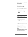
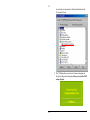
Use Web browser to set IP, gateway and subnet
1. Select “Network” in the SERVER category.
2. Fill out the blank and click “save” button.
3. Select “Save&Restart”, then click “Save and Restart”
button to save network information into Web Card and
reboot it.
4. Web Card needs about 30 seconds to reboot. Then IP setup
procedure is done. ePowerSwitch works now.
7
8
1
3
2
2. Setup via serial port
Before setup you need:
1. IP address: Get a valid IP address from administrator.
2. RS232 Cable.(enclose)
3. Dumb terminal software: ex: HyperTerminal in the
win95/98, NT, Win2000.
4. Default password: admin
8
The following steps guide you in connecting the ePowerSwitch
System through the serial port
1. Connect the RS232 port to a dumb terminal/PC with RS232
cable.
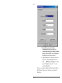
2. Setup terminal software
1. Open terminal software; select “Property” in
“File” category.
2. Setup as following image.
9
10
3. Press OK if you have the Windows
Communications screen or accept your
communication settings in the terminal emulation
package. The terminal/PC is now configured to
communicate with the ePowerSwitch.
4. Approximately three seconds after you turn on
AC power, the terminal displays “Check udram…”. Within 5 seconds, press “/” when
you see “Waiting five seconds…” to enter
console configuration.
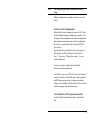
You are now ready to configure the ePowerSwitch. Refer to
the following Configuration section for a more detailed
discussion.
10
Note:
The telnet setup procedure is the same as the serial
setup.
When the configuration is completed, remember to save and
restart.
Serial or Telnet Configuration
ePowerSwitch System is temporarily connected to a PC with a
terminal emulation package or through telnet connection. The
advantage of telnet configuration over serial port configuration is
telnet operation can be done anytime, but serial configuration
has a short five seconds login window when the NIC Web
Card starts up.
Approximately three seconds after you turn on the power for
ePowerSwitch, the NIC card displays “Check u-dram…”
Press “/” when you see “Waiting five seconds…” to enter
console configuration.
You are now ready to configure the ePowerSwitch.
Enter the user name and password.
Use CTRL-W to move up, CTRL-Z to move down. From this
menu you can select to enter the IP address, Gateway address,
and MIB system group; you can set trap receivers, display
settings; reset the settings to default values; save the new values
and exit the program, and exit without saving.
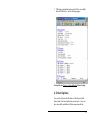
Use terminal to set IP, gateway and subnet
To set the IP address and Gateway address, select the first
item.
11
12
Figure 4 - IP Address for the ePowerSwitch System and
More
NOTE:
The minimum requirement to operate ePowerSwitch
System is to set the IP address.
If you want to return to the Main Menu, press Esc key.
For more information on IP addresses and net masks, see the
Reference section of the Appendix in this manual.
The ISP setup is for dial-up connection.
12
To Save and Exit
If you are satisfied with your configurations, be sure to save
them and exit.
3. Setup via USB port
Before setup you need:
1. IP address: Get a valid IP address from administrator.
2. USB Cable. (Enclose)
3. USB driver and USBSetup file. (Enclose in the disk)
1. Connect the ePowerSwitch to a Windows 98 PC through
an USB cable. If the PC prompts for a new driver, insert
the floppy provided. Uncheck update Windows 98 check
box. It will copy the proper driver from the floppy. Follow
the instructions. The new USB device will be recognized
when the driver is properly installed. No system start up is
required. See the picture below. Sometimes it takes longer
13
14
to see the device because the ePowerSwitch takes about
30 seconds to boot.
2. The “USB-interface power device” name must appear in
the System Properties dialog box before you run the USB
setup software.
14
3. USB setup is straightforward once the PC has successfully
detected USB device. See the following figure.
You need to run Device | Update & Restart before closing
4.Telnet Options
You can also Telnet to the IP address of the ePowerSwitch
System after it has been installed on your network. Once you
have successfully established a Telnet connection with the
15
16
adapter you may access the configuration menu as if you were
directly attached to it via the configuration port.
Moving cursor in telnet session is tricky. You need to select
VT100 cursor which is under Terminal | Preferences |
VT100 Arrows. After this setup, moving around menu system
is actually easier than in console setup mode.
Note:
You must have previously configured at least the IP
address and router information locally in order to
successfully make a Telnet connection.
5.Setup via Ethernet Cascaded Cable
Before setup you need:
1. IP address: Get a valid IP address from administrator.
2. Ethernet Cascaded Cable. (Not Enclose)
The following steps guide you in connecting the ePowerSwitch
System through the Ethernet port
1. Assign your PC’s IP address to dedicated IP address 216.87.151.1
2. Connect the ePowerSwitch’s Ethernet port and PC’s
network port with Ethernet cascaded cable.
3. Enter ePowerSwitch web default IP address216.87.151.196 by web browser, then Use Web browser to
set IP, gateway and subnet.
16
Configuration
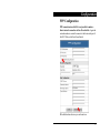
PPP Configuration
PPP connection is useful if it is not possible to make a
direct network connection to the ePowerSwitch. Again the
external modem is needed to connect to the front serial port of
the NIC Web card of the ePowerSwitch.
Fill in the blank as above in your web and save.
17
18
Remote operation procedure
1. The remote user may hang up after three rings when dial
in.
2. Based on the content of the PPP configuration,
ePowerSwitch will then automatically dial up to the
designated ISP and send the e-mail to the
designated e-mail address with the assigned IP
address from ISP.
3. User may browse and control ePowerSwitch with this
dynamic IP
4. Check the disconnection on the bottom of the PPP
configuration page after work.
18
User Management
Administrators can assign the maximum of 4 users to control the
outlet.
19
20
Software Update
This is the place you can upgrade the firmware when it is
available or bug fix.
20
ePowerSwitch Configuration
Each outlet can be individually programmed to enable ring
On/Off or reset. Power resume delay is convenient for
sequential startup. Name of each outlet can be labeled to
whatever you like it to be called. For example, server1, DSL
modem, webserver1, etc. Since 16 ePowerSwitches can be
daisy chained together to share one NIC, so each unit can be
individually named. The last item “Enable waiting device
shutdown” is dedicated to Microsoft Windows NT (4 and
2000, workstation and server) to have a safe shutdown. If you
installed an optional NT card inside the ePowerSwitch, there is
a delay time for the corresponding outlet of the NT card to off
the power for the safe shutdown functionality. The default delay
time is set up as 5 minutes.
21
22
To enable this safe shutdown function, in both NT and WIN
2000, you need to have three setting for the UPS to configure
it.
Connect the communication port on the rear of ePowerSwitch
to NT or WIN 2000 server with the PC Communication cable.
Connect the corresponding outlet on the rear of ePowerSwitch
to the NT or WIN 2000 server with the PC input power cord.
Check the corresponding box of safe waiting device shutdown
in ePowerSwitch configuration page to enable this function.
22
Scheduled shutdown
Scheduled shutdown can be accomplished here. Be careful
with which outlet you are working.
23
24
Verify The ePowerSwitch Operation
1. After you complete all configuration settings and connect the
ePowerSwitch System to the network, check the LINK status.
Power and Link lights should be on all the times. Collision
light turns on occasionally.
2. PING the ePowerSwitch System. Issue a PING command
from the NMS (Network Management Station).
a) If you do not get a response, check the card ’s
network connection and IP address.
3. Test the adapter with an NMS. Perform a “get” and a
“set.”
a) If the get or set commands fail, check the
ePowerSwitch System access controls. The manager
must have read permission to execute a get
command successfully and read/write permission to
execute a set command successfully.
(See Configuring the NMS section for a detailed discussion.)
Your ePowerSwitch is now installed and
completely functional.
24
Upgrade Firmware
TFTP Upgrade
With a Web browser, click on “Software upgrade”, input TFTP
server’s IP address and go. Make sure that the firmware file
(For example: ups.bin) is located in the default directory of the
TFTP server.
RS232 Serial Port Console Upgrade
The following steps guide you in connecting the ePowerSwitch
System through the serial port
1. Connect the RS232 port to a dumb terminal/PC with a null
serial cable.
2. Power on the NIC card of the ePowerSwitch;
? You have to reconfig all setting in ePowerSwitch after the
upgrade process has been completed successfully because all
25
26
the user data are lost.
26
Telephone Interface
You must have the optional phone card installed inside
the ePowerSwitch Server for all the functions discussed
here. Please check the dealer for the detail information.
Telephone access interface
1. Dial up the ePowerSwitch.
2. After three sequence rings, the ePowerSwitch will respond
by sending out 3 short beeps to the caller and waiting for
user to enter password.
3. User enters access password. The default password is
123456789#.
4. The ePowerSwitch will send out
a. 3 short beep to confirm successful login.
b. A long beep to deny access.
5. Once logged in, remote user can change ID Address:
333XXxx# is Change ID Address Command.
XX is Current Address, xx is Change ID Address.
Eg, 3330001# change ePowerSwitch ID from 0 to 1.
The default ID address for ePowerSwitch is 0.
The valid ID address for ePowerSwitch is 1, 2…16. The ID
address set for ePowerSwitch in daisy chain needs to be
different.
Note: If you had setup ePowerSwitch ID from by web, you
do not need to change ID here.
6. Once logged in, remote user can punch in 4 digits
27
28
ePowerSwitch ePowerSwitch
ID Address
Outlet
XX
X
01-16
1-8 ? A-H
9 ? All
Function
X
0-Off
1-On
2-Reset
Every command must add “#” in the end.
Eg, 0111# turn on ePowerSwitch01, outlet A,
0120# turn off ePowerSwitch01, outlet B,
0142# to reset ePowerSwitch01, outlet D (turn off
immediately, and on after 10 seconds )
Remote user may punch in 8 digits to delay reset, on or off.
Eg,
02813600# means turn ePowerSwitch02 outlet H on after
3600 minutes.
02803600# means turn ePowerSwitch02 outlet H off after
3600 minutes.
02823600# means reset ePowerSwitch02 outlet H after
3600 minutes.
Use combination of 0111XXXX# and 0112XXXX# to get
different delay for reset, or create a longer command.
XXXX max value is 9999, which is about 166 hours, or
6.94 days.
7. The ePowerSwitch will acknowledge received commands
by issuing 2 short beeps otherwise a long beep indicate
failure or not recognizable.
8. Change password. The default password is 123456789.
User has to enter previous password in order to change
password.
28
9. User enter 888XXX…..# or whatever previous password,
then ePowerSwitch responds with three short beeps
acknowledge access granted. Then user enter new
password as following:
888XXXXXXXXXX#, and ePowerSwitch acknowledge 2
short beeps, sounds like “what?” and user input
888XXXXXXXXXX# the second time to re-confirm, and
ePowerSwitch acknowledge 4 short beeps, indicating
password change completed.
10. Hang up to close access.
11. Each command string should be entered within 20 seconds,
the ePowerSwitch in a waiting loop to receive command.
After 180 seconds without user input, the device will logout
user.
12. “000#” key force to logout.
13. *” key cancel keyin error .
14. User interface use minutes as unit.
29
30
Appendix
This appendix has three sections: Reference, Glossary, and
Troubleshooting.
Reference
This section discusses Communities, IP Addresses, Sub net
masking, and routers/gateways.
Communities
A community is a string of printable ASCII characters that
identifies a user group with the same access privileges. For
example, a common community name is “public.”
For security purposes, the SNMP agent validates requests
before responding. The agent can be configured so that only
trap managers that are members of a community can send
requests and receive responses from a particular community.
This prevents unauthorized managers from viewing or changing
the configuration of a device.
IP Addresses
Every device on an internetwork must be assigned a unique IP
(Internet Protocol) address. An IP address is a 32-bit value
comprised of a network ID and a host ID. The network ID
identifies the logical network to which a particular device
belongs. The host ID identifies the particular device within the
logical network. IP addresses distinguish devices on an
internetwork from one another so that IP packets are properly
transmitted.
30
IP addresses appear in dotted decimal (rather than in binary)
notation. Dotted decimal notation divides the 32-bit value into
four 8-bit groups, or octets, and separates each octet with a
period. For example, 199.217.132.1 is an IP address in dotted
decimal notation.
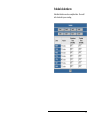
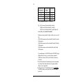
To accommodate networks of different sizes, the IP address
has three divisions—Classes A for large, B for medium, and C
for small. The difference among the network classes is the
number of octets reserved for the network ID and the number
of octets reserved for the host ID.
Class
A
B
C
Value of First
Network ID
Octet
1-126
first octet
128-191
first two octets
192-223
first three octets
Host ID
Number of Hosts
last three octets
last two octets
last octet
16,387,064
64,516
254
Any value between 0 and 255 is valid as a host ID octet except
for those values the InterNIC reserves for other purposes.
Value
0, 255
127
224-254
Purpose
Subnet masking
Loopback testing and interprocess communication on local devices
IGMP multicast and other special protocols
Subnetting and Subnet Masks
Subnetting divides a network address into subnetwork
addresses to accommodate more than one physical network on
a logical network.
For example: A Class B company has 100 LANs (Local Area
Networks) with 100 to 200 nodes on each LAN. To classify
the nodes by its LANs on one main network, this company
31
32
segments the network address into 100 subnetwork addresses.
(If the Class B network address is 150.1.x.x, the address can
be segmented further from 150.1.1.x through 150.1.100.x.)
A subnet mask is a 32-bit value that distinguishes the network
ID from the host ID for different subnetworks on the same
logical network. Like IP addresses, subnet masks consist of
four octets in dotted decimal notation. You can use subnet
masks to route and filter the transmission of IP packets among
your subnetworks. The value “255” is assigned to octets that
belong to the network ID, and the value “0” is assigned to
octets that belong to the host ID.
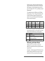
For the example above, if you want all the devices on the
subnetworks to receive each other’s IP packets, set the subnet
mask to 255.255.0.0. If you want the devices on a single
subnetwork only to receive IP packets from other devices on its
own subnetwork, set the subnet mask to 255.255.255.0 for the
devices on that subnetwork.
Subnet Mask
0.0.0.0
255.0.0.0
255.255.0.0
255.255.255.0
32
Routing and Filtering
IP packets are transmitted to all
devices.
IP packets are only transmitted to
devices whose IP address’s first octet
matches the sender’s IP address’s first
octet.
IP packets are only transmitted to
devices whose IP address’s first two
octets match the sender’s IP address’s
first two octets.
IP packets are only transmitted to
devices whose IP address’s first three
octets match the sender’s IP address’s
first three octets.
Gateways
Gateway, also referred to as a router, is any computer with two
or more network adapters connecting to different physical
networks. Gateways allow for transmission of IP packets
among networks on an internetwork.
33
34
Glossary
The Glossary section defines the terms used in the
ePowerSwitch System -MP environment.
Agent
Dry Closure Input
Dry Closure Output
EtherNet
Gateway
IP
IP Address
MAC
MIB
NC
NIC
NMS
34
Implemented SNMP applications in network elements
(hosts). Agents perform the network management’s
functions as requested by the network administrator from
an NMS.
Non-powered contact type inputs—switch, relay contact,
open-collector.
Form C dry-contact outputs which are common, normally
open, or normally closed.
Local Area Network technology, originally developed by the
Xerox Corporatio n, can link up to 1,024 nodes in a bus
network. EtherNet provides raw data transfer in a rate of
10 megabits/sec. with actual throughputs in 2 to 3
megabits/sec. using a baseband (single-channel)
communication technique. EtherNet uses carrier sense
multiple access collision detection (CSMA/CD) that
prevents network failures when two devices attempt to
access the network at the same time. LAN hardware
manufactures use EtherNet protocol; their products may
not be compatible.
A computer that attaches to a number of networks and
routes packets between them. The packets can be
different protocols at the higher levels.
Internet Protocol—The TCP/IP standard protocol defines
the IP datagram as the unit of information passed across a
network.
Internet Protocol Address—A 32-bit address assigned to
hosts participating in a TCP/IP network. The IP address
consists of network and host portions. It is assigned to an
interconnection of a host to a physical network.
Medium Access Control—The net work layer between the
physical and the datalink layers. Specifically, the physical
(hardware) address exists in this layer.
Management Information Base—The database, i.e., set of
variables maintained by a gateway running SNMP.
Normally Closed —Refers to a contact switch that is
normally closed.
Network Interface Controller—The hardware interface to the
physical connection to the network.
Network Management Station
NO
OID
Personality
Router
RS-232
SNMP
Sub-Agent
TCP/IP
TES
TFTP Server
UDP/IP
UPS
Normally Open—Refers to a contact switch that is normally
open.
Object Identifier—The variables defined in a MIB.
The current device specific software uploaded to the
ePowerSwitch System
A computer that manages traffic between different network
segments or different network topologies. It directs the
destination IP address. The network media can be
different, but the higher level protocols must be the same.
A specification for serial communication between data
communication equipment and computers.
Simple Network Management Protocol—A standard protocol
used to monitor IP hosts, networks, and gateways. SNMP
defines a set of simple operations that can be performed
on the OIDs of the MIBs managed by the monitored
Agents. It employs the UDP/IP transport layer to move
its object between the Agents and the NMS.
A software module that manages specific MIB sub-groups for
an Agent. They communicate with the Agent using a
SMUX (multiplexer).
Transmission Control Protocol/Internet Protocol—A
protocol suite used by more than 15 million users with a
UNIX association and widely used to link computers of
different kinds.
Terminal Emulation Software—Communications program to
transform a personal computer into a terminal for the
purpose of data communications.
Trivial File Transfer Protocol Server—A host to provide
services according to TFTP; a TCP/IP standard protocol
for file transfer with minimal capability and overhead
depending on UDP for its datagram delivery service.
User Datagram Protocol/Intern et Protocol—A TCP/IP
standard protocol. It enables transfer of information
between applications running on different host. It is
referred to as an unreliable, connectionless datagram
delivery service.
Uninterruptible Power Supply—A device that supplies power
to your system with rechargeable batteries if there is an
AC power failure.
35
36
Troubleshooting
Problem:
The TES (Terminal Emulation Software) does not display
anything.
Solution:
Make sure the TES’s communication parameters are correct. They
should be 115200 baud rate, no parity, 8-data bits, and 1 stop bit.
The cable is a null serial cable.
PROBLEM:
The NMS cannot ping the ePowerSwitch System.
Solution:
Make sure the network connection to the ePowerSwitch System is
good.
Solution:
Make sure the cable is in good condition.
Solution:
Make sure to set the Community String
Name the community with any lowercase name. (A UPS monitors a
designated community.)
Solution
36
Make sure to set the Manager Table.