1
Remote Power Manager (RPM)
User’s Manual
34000181 Rev2
Table of Contents
Warnings .................................................................................. 3
Quick Install Procedure ............................................................. 4
Introduction ............................................................................... 8
Remote Power Manager (RPM) Features.................................. 8
RPM Package .................................................................... 8
Setup Procedure ....................................................................... 9
Setup via the USB Port....................................................... 9
Setup via the Serial Port................................................... 19
Setup via the Ethernet Port............................................... 27
Telnet Configuration................................................................ 29
Web-Based Configuration ....................................................... 35
Power Management Software Setup Procedure ...................... 46
Windows NT Server ......................................................... 46
Windows 2000 Server ...................................................... 49
Software Upgrade Procedures................................................. 53
Software Upgrade via TFTP ............................................. 53
Software Upgrade via Serial Port...................................... 56
API Function Library ............................................................... 60
Telephone Access Interface .................................................... 63
Daisy Chaining........................................................................ 64
Troubleshooting ...................................................................... 65
Appendix................................................................................. 66
Communities .................................................................... 66
Gateways ......................................................................... 66
IP Address........................................................................ 66
Subnetting and Subnet Masks .......................................... 67
Glossary.................................................................................. 68
Obtaining Technical Assistance............................................... 69
Limited Product Warranty ....................................................... 70
2
NOTICE: This equipment has been tested and found to comply with the limits for a “Class A” digital device, pursuant to
Part 15 of the FCC rules. These limits are designed to provide reasonable protection against harmful interference when
the equipment is operated in a commercial environment. This equipment generates, uses and can radiate radio
frequency energy and if not installed and used in accordance with the instruction manual, may cause interference to radio
communications. Operation of this equipment in a residential area is likely to cause harmful interference, in which case
the user will be required to correct the interference at the user’s own expense.
This digital apparatus does not exceed the “Class A” limits for radio noise emissions from digital apparatus set out in the
Radio interference regulations of the Canadian Department of Communications.
Trademarks
Remote Power Manager (RPM) is a trademark of Para Systems, Inc.
IBM, IBM NetView/6000 are trademarks or registered trademarks of International Business Machines Corp.
Hewlett-Packard, HP, HP Open View are trademarks or registered trademarks of Hewlett-Packard Company.
Microsoft, MS, MS-DOS, XENIX are registered trademarks and Windows, Windows NT, LAN Manager, and Win32 are
trademarks of Microsoft Corporation.
NT is a trademark of Northern Telecom Limited.
Novell and NetWare are registered trademarks, and NLM is a trademark of Novell, Inc.
SunConnect SunNet is a trademark or registered trademark of Sun Microsystems Computer Corporation.
Xerox is a registered trademark of the Xerox Corporation.
Conventions Used In This Guide
This guide uses these conventions:
Bold italic print, as shown in this example, indicates field names, menu items, or values in the Computer Interface Card
(CIC) software agent.
Bold print, as shown in this example, indicates filenames, directories, or items that you must type exactly as they
appear.
Italic print words or letters in braces { } indicate values that you must supply. For example: {drive}:\setup
Italic print words or letters in brackets < > indicate keys to press. If two keys are separated by a + plus symbol, then the
first key should be pressed and held down while pressing the second key. For example: <alt+enter>.
Note: Notes contrast from the text to emphasize their importance.
Warning:
These messages alert you to specific procedures or practices; serious consequences
may result including injury if you disregard them.
Copyright 2002
Para Systems, Inc.
Unauthorized reproduction prohibited.
3
Quick Install Procedure
This section will guide you through the quick installation of the RPM.
1.
2.
3.
Install mounting brackets: page 4.
Install all input and output connections: pages 5 and 6.
Program you IP address (this is the minimum requirement to use the RPM): page 9.
For USB setup:
a) Insert Driver Setup Diskette in floppy drive.
b) Run Setup.exe from floppy drive.
c) Program IP address per Page 15.
NOTE: Default user name is: admin.
NOTE: Default password is admin.
At this point the RPM is ready for normal operation. Review the (section Quick Install) pages 4-7 to become familiar with
the general functions. Review the entire User’s Manual in detail for more in-depth functions.
4.
5.
6.
7.
Set RPM’s front control buttons for Internet/remote
Use browser to monitor and control.
Note: Smart phone default password must include # as last character
For Windows NT/2000 Server shutdown setup, use control panel / UPS configure (page 46).
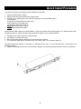
The RPM comes with brackets for mounting in a standard 19-inch rack. To mount the RPM into a rack perform the
following procedure:
1. Attach the mounting brackets to the unit as shown, using the four retaining screws provided for each of the brackets.
4
2.
3.
Choose a location for the brackets. A notched hole on the vertical rail denotes the middle of a U slot.
Align the mounting holes of brackets with the notched hole on the vertical rail and attach with the retaining screws.
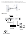
RPM-Front Panel
Setup via USB Port
Setup via RS232 Port
Setup via Ethernet Port
iLink Port is
for Daisy Chaining and
the RPM/UPS Interface Card
An External Modem can be used
to control the RPM.
Connect to the network to
control the RPM
Ring On/Reset Port – Connect a
telephone line to control the RPM
5
Receptacle Control Status LED (Green)
Receptacle Status LED (Red)
Active Module LED (Yellow)
Momentary switch for Receptacle
Master Power Switch
Receptacle Status LED (Red): When the LED is illuminated the receptacle is on and providing AC Power. When the
LED is off the receptacle is not providing AC Power.
Receptacle Control Status LED (Green): When the control LED is illuminated, the momentary switch is disabled and
the output receptacle is programmed for remote control. When the LED is off, the momentary switch is active and the
receptacle may be turned on or off by pressing and releasing the switch. Pressing and holding the momentary switch for
three seconds will change the state from remote to local control.
Active Module LED (Yellow): When illuminated this LED indicates which module or client is currently being accessed
via remote control.
Momentary switch for receptacle control: Pressing and holding the momentary switch for three seconds will change
the state from remote to local control. Pressing and holding the momentary switch for one second will change the state
from on to off or from off to on.
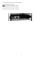
RPM-Rear Panel
Windows NT/2000 Server Ports A-H: Provides a safe and logical shutdown for Windows NT/2000 Server. Port A
controls receptacle A; Port B controls receptacle B, etc (optional). Connect the RJ11 to RS232 cable to the appropriate
port (A-H) on the RPM and to the appropriate COM port on the server.
AC Power Receptacles A-H
Windows NT/2000 Server Ports A-H
Connect the input power cord to utility power
6
Program your RPM’s IP address per USB, RS232 or Ethernet.
For USB setup procedure, see page 9.
NOTE: this method requires Windows 98 or higher.
For RS232 Serial Port setup procedure, see page 19.
For Ethernet / Network setup procedure, see page 27.
7
Introduction
The Remote Power Manager (RPM) is a network-manageable, intelligent power control unit designed to provide control
of power for up to eight electrical devices.
NOTE: If the RPM is turned off by the master power switch, you have to wait approximately thirty seconds before
restarting the RPM to allow the RPM to internally reset.
RPM Features
Internet ready — Individually control each of the eight AC receptacles by using a Web Browser.
Remotely and individually reboot locked up servers.
If the network locks up, you can use the telephone to control the RPM to shutdown or to reboot locked up devices
or servers.
Sequentially apply power to the equipment that is plugged into the RPM.
Multiple OS support—As long as there is Network Management software present.
Remote setup support— Once an IP address is assigned, the rest can be setup remotely through telnet commands.
USB port setup—In addition to the regular serial port setup, this adapter also has a USB setup feature for initial
setup of this card. (Requires Windows 98 or higher)
Remote Control—Turns each of the AC receptacles on/off when the NMS sends the proper command.
Remote Software upgrade support - The Remote Power Manager supports Software upgrade through TFTP server
remotely. A serial upgrade method is available too.
RPM Package
The standard RPM package contains a Remote Power Manager Unit with supporting hardware and software.
components of your package are:
1.
Remote Power Manager Unit
2.
Rack mount Brackets
3.
AC Power Cord
4.
USB Cable
5.
DB9 Female-to-Female Serial Cable
6.
RJ11 to RS232 Windows NT/2000 Server Cable (optional)
7.
RJ11 Telephone Cable
8.
3.5“ Diskette (includes USB device driver, USB setup software, TFTP Server files and the User’s Manual)
Figure 1- Remote Power Manager Unit
8
The
Setup Procedure
This section describes the setup procedures of the RPM when you connect it to the network.
NOTE: The minimum requirement to operate the RPM is to set the IP address.
There are four different ways to setup the RPM.
1.
Setup the IP Address via the USB port (software included). Requires Windows 98 or higher.
2. Setup the IP Address via the Serial port using Hyper Terminal. Requires Hyper Terminal version 3.0 or higher.
3. Setup the IP Address via the Ethernet Port by using the ARP command (first time only), then use the Web
Configuration to finish the setup.
4.
Setup the IP Address via the Ethernet Port by using the ARP command (first time only), then use the Telnet
Configuration to finish the setup.
Setup via the USB Port (Requires Windows 98 or higher)
The following items must be obtained before attempting to setup the RPM: A valid IP Address, a USB Cable (provided),
the USB Driver/USB setup file (enclosed diskette) and a PC with Windows 98 or higher.
1.
2.
3.
4.
5.
6.
7.
8.
Connect one end of the USB Cable to the USB Port on the computer.
Connect the other end of the USB Cable to the USB Port on the RPM.
Plug the RPM’s power cord into the AC wall outlet.
Plug the computer’s power cord into the RPM’s output receptacles.
Turn on the RPM.
Turn the computer on and let it boot-up.
Insert the floppy diskette with the USB Driver/USB setup files into the appropriate drive.
Windows will display the following message (first time only):
New Hardware Found
USB Device
Windows has found new hardware
and is locating the drivers for it.
9
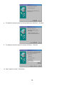
8.
The Hardware wizard will guide you through installing the USB Driver. Click Next.
9.
The Hardware wizard will search for the best USB Driver. Click Next.
10. Check, Specify a location. Click Browse.
10
11. Open the appropriate 3.5″ Floppy Drive. Open the USB folder. Open the Driver folder. Click OK.
12. Windows will search for the new USB Driver. Click Next.
13. Windows has found the USB Driver for the USB device. Click Next.
11
14. Windows has found the best Driver for this USB device. Click Next.
15. Windows is copying the USB Driver files to your “C:” drive. Click Next.
16. Windows is finished installing the USB Driver. Click Finish.
12
17. On the Desktop, right click “My Computer”. Open Properties.
18. Open the Device Manager. Wait for approximately 30 seconds for the “Human Interface Device” to appear. Open
the Human Interface Device. Click on “Usb-interface power device”. Click OK.
13
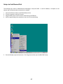
19. Open Windows Explorer. Open the appropriate 3.5″ Floppy Drive. Open the USB folder. Open USBSetup.exe.
Note: The USB setup icon must be green before you can run the USB setup program.
20. The Power Device Configuration tool is loading.
14
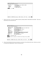
21. This is the Power Device Configuration Tool screen. On the Toolbar open Configuration. Then open System.
22. This is the System Parameter Configuration screen fill in all the information: the IP Address, the Subnet Mask, the
Default Route (Gateway) and the DNS Server. Use the Tab key to move from one field to the next field. Then click
OK.
15
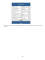
23. This is the Power Device Configuration Tool screen. After you have entered in all of the pertinent information, you
have to Update and Restart to save all the information that was entered into the System Parameter Configuration
screen. The Update and Restart icon (with the red arrow) is right beneath the “Device” drop down menu.
24. Enter the Supervisor Name and the Supervisor Password.
Password is admin (lower case). Then click OK.
16
The Default Supervisor Name and the Supervisor
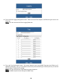
25. This is the Power Device Configuration screen. Click Yes to Update the Power Device
26. This is the Device Parameter Transmitting screen. The Power Device is being Updated.
17
27. The Power Device has been successfully updated. Click OK.
28. The Power Device has to be Restarted. Click Yes.
29. The USB Setup Procedure is complete. The RPM is ready for normal operation. Unplug the USB Cable from the
RPM and from the computer. Plug the Ethernet Cable into the RPM and after about thirty seconds the Link LED will
start blinking, now you can communicate with the RPM. The Ping command is supported at this time. Startup a
Browser and type in the IP Address. The default password is admin (lower case). Go to the section in the User’s
Manual titled “Web-Based Configuration” it will guide you through the Web pages.
18
Setup via the Serial Port
NOTE: When using Hyper Terminal use Version 3.0 or higher.
The following items must be obtained before attempting to setup the RPM: A valid IP Address, a DB9 female-to-female
Serial Cable (provided). There are a wide variety of Terminal Emulation packages, but for the most part they should be
very similar. The following setup procedure is using Hyper Terminal.
1.
2.
3.
Connect one end of the DB9 female-to-female Cable to the Serial port on the computer.
Connect the other end of the DB9 female-to-female cable to the Serial port on the RPM.
Turn the computer on and let it boot-up.
4.
From the Desktop open the Start menu. Pick Programs, Accessories, Communications and Hyper Terminal. Open
Hyper Terminal (requires version 3.0 or higher).
19
5.
Open HYPERTRM.EXE.
6.
Enter a name (RPM). Click OK.
7.
Connect using the appropriate Com port. Click OK
20
8.
Configure the port settings. Bits per second: “115200”, Data bits: “8”, Parity: “None”, Stop bits: “1”, Flow control:
“None”. Click OK
9.
On the Toolbar open the File menu, and then open Properties.
21
10. Open the Settings Tab. Function, arrow and ctrl keys act as: Terminal Keys, Backspace key sends: Crtl+H,
Emulation: VT100, Telnet terminal: VT100, Backscroll buffer lines: 500. Click OK.
11. Plug the RPM’s power cord into the AC outlet and turn the RPM on.
12. When the message “Press ‘/’ key within 5 seconds to enter console configuration” appears press the forward slash
key (/) within the 5 seconds or the RPM will time out and then you have to start over.
13. Next you will be asked for the User Password. The default password is admin. Enter the password, then hit enter.
22
14. Ctrl-Z moves the cursor down and Ctrl-W moves the cursor up. Pick System, then hit enter.
15. Enter in the IP Address (required), the Gateway Address, the Subnet Mask and the DNS. Hit the “Escape” key to
return to the main menu.
23
16. Enter in the PPP Type, Server IP, Client IP, Server Profile, Dial number, the ISP account/password and the
enable/disable dial-out interface (not required). Hit the “Escape” key to return to the main menu.
17. Arrow down to Mail and hit enter. Enter in the SMTP Server (not required). The user can add or delete email
addresses. Hit the “Escape” key to return to the main menu.
24
18. Arrow down to Trap and hit enter. This screen allows the user to send Traps about the UPS to ten IP Addresses (not
required). Also, you may determine the severity levels and what type of access, read only or read and write, to
assign to a particular IP manager. Hit the “Escape” key to return to the main menu.
19. Once you have finished with the entire configuration, cursor down to Save_Restart and hit enter. Make sure you
want to overwrite the old settings (y/n)? Hit the y key, then hit enter.
25
20. After rebooting the system, the new settings will be activated. Reboot (y/n)? Hit the y key then hit enter. Once the
system has rebooted, cursor down to Exit then hit enter.
21. The Serial Setup Procedure is complete. The RPM is ready for normal operation. Unplug the DB9 female-to-female
Serial Cable from the RPM and from the computer. Plug the Ethernet Cable into the RPM and after about thirty
seconds the Link LED will start blinking, now you can communicate with the RPM. The Ping command is supported
at this time. Startup a Browser and type in the IP Address. The default password is admin (lower case). Go to the
section in the User’s Manual titled “Web-Based Configuration” it will guide you through the Web pages.
26
Setup via the Ethernet Port
The following items must be obtained before attempting to setup the RPM: A valid IP Address, a Computer on the
network and an Ethernet cable connected to the network.
1.
2.
3.
4.
Connect the Ethernet cable to the RPM’s Ethernet Port.
Turn the computer on and let it boot-up.
Plug the RPM’s power cord into the AC outlet and turn the RPM on.
Wait for approximately thirty seconds for the Link LED to start blinking.
5.
From the Desktop open the Start menu. Pick Programs and then open the MS-DOS Prompt.
27
6.
This is an example. At the MS-DOS Prompt type: arp –s 192.166.7.19 52-54-4c-19-ad-90. Then hit enter. The first
string is the IP Address; the second string is the MAC Address (which can be found on the front of the RPM).
7.
At the MS-DOS prompt type: route add 192.166.7.19 210.67.4.155. Then hit enter. The first string is the IP Address
and the second string is the Gateway Address.
NOTE: The PING Command is not supported at this time.
8. At the MS-DOS Prompt type exit. Then hit enter.
9. There are two options to finish setting up all of the parameters. Option #1 The Web-Based Configuration, Option #2
Telnet.
10. Option #1. Startup a Browser and type in the IP Address. The default name and password is admin (lower case).
Go to the section in the User’s Manual titled “Web-Based Configuration” it will guide you through the setup of all the
parameters.
11. Option #2. Go to the section in the User’s Manual titled “Telnet Configuration” it will guide you through the setup of
all the parameters.
28
Telnet Configuration
This section will guide you through finishing the configuration of the RPM using Telnet.
NOTE: You must complete the appropriate Setup Procedure before proceeding with the Telnet Configuration.
NOTE: You must have given the RPM an IP Address.
The Ethernet cable is connected to the RPM and the RPM is on.
1.
From the Desktop open the Start menu. Pick Programs and then open the MS-DOS Prompt.
29
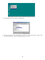
2.
This is an example. At the MS-DOS Prompt type telnet 192.166.7.19 (IP Address). Then hit enter.
3.
Next you will be asked for the User Password. The default password is admin. Enter the password, then hit enter.
4.
Pick Terminal, then open Preferences.
30
5.
Check VT100 Arrows. You can leave the Block Cursor checked or you can uncheck the Block Cursor depending on
your preference. Then click OK.
6.
Pick System, then hit enter.
31
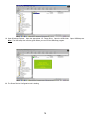
7.
Pick IP, then hit enter. Input your IP Address (required), Gateway Address, Subnet Mask and the DNS. Then hit the
left arrow key to exit to the main menu.
8.
Once you have finished with the entire configuration, arrow down to Save_Restart and hit enter. Make sure you want
to overwrite the old settings (y/n)? Hit the y key, then hit enter.
32
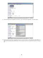
9.
After rebooting the system, the new settings will be activated. Reboot (y/n)? Hit the y key then hit enter.
10. The RPM has rebooted to activate the new settings. Click OK. Arrow down to exit then hit enter.
33
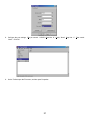
11. On the Toolbar pick Connect, then open exit.
12. At the MS-DOS Prompt type exit, then hit enter.
13. The Telnet Configuration is complete. The RPM is ready for normal operation. After about thirty seconds the Link
LED will start blinking, now you can communicate with the RPM. The Ping command is supported at this time.
Startup a Browser and type in the IP Address. The default password is admin (lower case). Go to the section in the
User’s Manual titled “Web-Based Configuration” it will guide you through the Web pages.
34
Web-Based Configuration
This section will guide you through the Web-Based-Configuration and the Web Pages of the Remote Power Manager
(RPM).
NOTE: You must complete the appropriate Setup Procedures before proceeding with the Web-Based-Configuration.
The Ethernet cable is connected to the RPM and the RPM is on.
1.
2.
3.
Startup a Web browser.
Type in your IP Address.
Next you will be asked for the User Name and Password. The default Name and Password is admin. Enter the
password, then hit enter.
4.
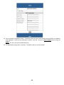
This is the screen where you can set the System Information parameters for the SNMP MIB2. After you have
finished filling in all of the information, click Save.
35
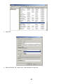
5.
This is the screen where you can set the Network parameters. After you have finished filling in all of the information,
click Save.
36
6.
The PPP connection is useful if it is not possible to make a direct network connection to the RPM. An external
modem is needed to connect to the front serial port of the RPM.
NOTE: The user must complete one of the Setup Procedures and fill in all of the information in the PPP
Configuration before the Dial-up Function will work.
After dialing in the remote user must hang up after the third ring. Based on the information that the user puts into the
PPP configuration, the RPM will automatically dial up to the designated ISP and send an email to the designated
email address with the assigned IP address from the ISP. The user may browse and control the RPM with this
dynamic IP address. When the user is ready to exit click the "Disconnect Now " button at the bottom of the screen.
37
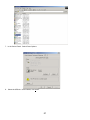
7.
This is the screen where you set the Date and Time. After you have finished filling in the information, click Save.
8.
This is the screen where you can change the Administrator’s Name and Password. After you have finished filling in
the information, click Save.
NOTE: The Supervisor’s name and password can be from 1 to 19 digits. The Supervisor’s name and password is
not limited to an alphanumeric character (i.e. a#1b$2z%9).
NOTE: Be sure to write down your Supervisor’s name/password and keep it in
a safe place. If the user forgets the name/password the RPM will have to be
Flash Upgraded before the user can access the RPM.
38
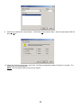
9.
This screen allows the user to setup the Application Programming Interface. The Application Programming Interface
can be accomplished by two methods, Windows API through the Ethernet connector or RS232 API through the
RS232 connector (additional software is required for both methods). See the section API Function Library. After you
have finished filling in the information, click Save.
10. This is the screen where the administrator can give certain rights to certain users. After you have finished filling in
the information, click Save.
39
11. This is the screen where you can upgrade to the latest version of software. See the section on Software Upgrade
Procedure.
12. After filling in all of the information be sure to Save and Restart before exiting the program.
13. This screen allows the user to Logout. If, any changes were made be sure to Save & Restart before exiting the
program.
40
14. This screen allows the user to see the status of the RPM. The user can control each receptacle individually or all of
them at the same time. The RPM has to be setup in the remote mode to control the receptacles via the Internet.
The RPM can also be setup for the local mode. The user can control the receptacles by the momentary switches on
the front panel.
15. Each outlet can be individually programmed to enable ring On/Off or reset. The power resume delay is convenient
for sequential startup. The name of each outlet can be labeled to whatever you like it to be called (i.e. server1, DSL
modem or webserver1). Since 16 RPMs can be daisy chained together to share one CIC, each unit can be
individually named. The safe shutdown feature has a configurable delay time to safely shutdown the Windows
NT/2000 server.
NOTE: The user must setup the Power Management Software in Windows NT/2000 Server (see page 46).
41
16. This screen allows the User to schedule daily/weekly shutdowns and restarts of individual receptacles (be sure to
check the appropriate box). The safe shutdown is dedicated to Microsoft Windows NT (4.0, 2000, workstation and
server). Click on the corresponding outlet to enable the safe shutdown feature. The safe shutdown feature has a
configurable delay time to safely shutdown the Windows NT/2000 server. Then click Save.
NOTE: The user must setup the Power Management Software in Windows NT/2000 Server (see page 46).
17. This is the Event Action screen. The user chooses an event from the Event List. Then the user chooses one of the
four ways to configure the event.
42
18. This is the Pager Configuration screen. Connect an external modem to the RS232 port of the RPM. When the
chosen Event happens, the RPM will page the number. After dialing in the remote user must hang up after the third
ring. Based on the information that the user puts into the PPP configuration, the RPM will automatically dial up to
the designated ISP and send an email to the designated email address with the assigned IP address from the ISP.
The user may browse and control the RPM with this dynamic IP address. When the user is ready to exit click the
"Disconnect Now " button at the bottom of the screen. The user must check the Paging Enable Box.
NOTE: The user must complete the PPP Configuration for the Pager Function to work.
19. This is the Broadcast Configuration screen. When the chosen Event happens, the RPM will broadcast the message.
The user will have to install the Message Capturing Program to be able to capture the broadcasted messages. The
Message Capturing Program (UpsClient.exe) is located on the disk with the User’s Manual. The program has to be
on before it will capture the messages. The user can install the program on their desktop.
NOTE: The user must check the appropriate broadcast box.
43
20. This is the Event Logging Configuration screen. When the chosen Event happens, the RPM will log the event in the
Event Log.
NOTE: The user must check the Event Logging Enable box.
21. This is the Trap Configuration screen. This screen allows the user to send SNMP Traps about the RPM to ten IP
Addresses (managers). Also, you may determine the severity levels and what type of access (read only or read and
write) to assign to a particular IP manager.
NOTE: The user must check the Trap Enable box and the Accept box.
NOTE: An NMS is required to send and get the SNMP Traps.
44
22. This is the Email Configuration screen. This screen allows the user to send emails about the RPM to five different
email addresses. Once all of the information is filled in, click OK. Be sure to Save & Restart before exiting the
program.
NOTE: The user must check the Mail Enable box.
23. The Web-Based Configuration is complete. The RPM is ready for normal operation.
45
Windows NT/2000 Server Power Management Software Setup Procedure
The RPM can be setup to perform a safe and logical shutdown of a Windows NT/2000 Server (see pages 41, 42). The
Power Management Software in Windows NT/2000 Server must be configured correctly. Once the Power Management
Software has been configured, the user can perform a safe and logical shutdown by turning off the appropriate output
receptacle (see page 41).
NOTE: The RPM must have the NT cards installed to perform the safe and logical shutdown of Windows NT/2000
Server.
Windows NT Server Power Management Software Setup Procedure
1.
2.
3.
Open the Startup menu.
Open Settings and then the Control Panel.
Click on the Services icon.
46
4.
Double click on UPS.
5.
Startup Type: Select Automatic and click OK, then click Close.
47
6.
In the Control Panel. Select the UPS icon.
7.
Check all the boxes as shown. Select the appropriate COM Port then, click OK. The Power management Software
Procedure is complete. The RPM is ready for normal operation.
NOTE: The UPS Interface Voltages must be set to positive.
48
Windows 2000 Server Power Management Software Setup Procedure
1.
2.
3.
Open the Startup menu.
Open Settings and then the Control Panel.
Open Administrative Tools.
4.
Open Services.
49
5.
Open UPS.
6.
Select the General Tab. Startup Type: Select Automatic and click OK.
50
7. In the Control Panel. Select Power Options.
8.
Select the UPS tab. Under Details, click Select.
51
9.
Under Select manufacturer, select Generic. Under Select model, select Custom. Select the appropriate COM Port
then, click Next.
10. Check all the boxes as shown then, click Finish. The Power management Software Procedure is complete. The
RPM is ready for normal operation.
NOTE: The UPS Signal Polarity must be set to negative.
52
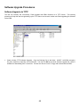
Software Upgrade Procedures
Software Upgrade via TFTP
The user can remotely and conveniently, Flash Upgraded the RPM’s Software via a TFTP Server. The following
procedure will step the user through setting up the TFTP Server at the user’s location and Flash upgrading the Software
for the RPM.
1.
Create a folder (TFTP Software Upgrade). Copy the following files to the folder: 2002AT ver2.0.BIN (example),
file_id.diz, tftp32.exe, tftp32.hlp, and Vendinfo.diz. The first file .BIN is the actual Software upgrade file, which is
available for downloading from our web site. The last four files are on a 3.5” floppy disk included with the RPM.
53
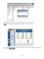
2.
Open the tftp32.exe file. The above screen will open. This is the TFTP Server’s IP address.
NOTE: DO NOT close the tftp32.exe program until the Software Flash Upgrade is complete.
3.
Open a Web browser and input the IP address of the RPM that is going to be Flash Upgraded. Once the Web page
is open, select “Software Upgrade”.
54
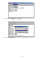
4.
Input the TFTP Server IP address and the Software Upgrade file name (.BIN), then click YES.
5.
The TFTP Server is Flash Upgrading the RPM to the new version of Software. The Software Upgrade takes
approximately thirty-five minutes to complete.
55
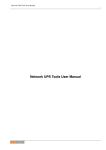
6.
The transferring of the Software Upgrade file is complete. Close the tftp32.exe program. Open “Save & Restart”.
The “Save & Restart” function must be performed to save all of the changes. The RPM is ready for normal
operation.
Software Upgrade via Serial Port:
The following items must be obtained before attempting to upgrade the RPM: The Software upgrade file, a DB9 femaleto-female Serial Cable (provided). There are a wide variety of Terminal Emulation packages, but for the most part they
should be very similar. The following upgrade procedure is using Hyper Terminal.
NOTE: When using Hyper Terminal use Version 3.0 or higher.
1.
2.
Go to the section titled “Setup via Serial Port” (page 19) and follow steps 1 through 10.
Plug the RPM’s power cord into the AC outlet and turn the RPM on.
3.
Once the message “Check u-dram” appears hit the “c” key. Then at the cursor type “upgr” for RPMs with
MAC Addresses beginning with “52” and “upall for RPMs with MAC Addresses beginning with “00”, then hit
enter. Once the User hits enter, you have approximately thirty seconds to complete the next four steps.
56
4.
Go to the tool bar and select Transfer. Open Send File.
5.
Select “X modem” under Protocol.
57
6.
Click Browse. Look in the location where the Software upgrade file is located. Select the File name: “.bin”
and click open.
7.
Click Send.
58
8.
The Software upgrade will take approximately eight minutes to complete.
9.
The Software upgrade is complete.
NOTE: The user has to reconfigure all of the settings after the Software upgrade is complete, because all of the
user’s settings will default to the original default settings.
59
API Function Library
ISWPollID(String Auth)
Arguments:
Input : String
Output : Boolean
Description:
Get iSWITCH ID Address.
The first input parameter is authenny code. ISWPollID is a function call to get the iSWITCH device ID address. If more
than one of the iSWITCH device you want to poll their ID then the return string will separated each ID number by “,”.
If this API execute successfully, you will get return code: true and you can use other function to get relative information.
ex(1) iSWITCH05 iSWITCH06 getReturnValueSize( ) will get 2 getAllReturnValue( ) will get iSWITCH05•iSWITCH06; if
over one set of parameter, we use ” ,”delima point to getReturnValue(1) will get iSWITCH05 point to getReturnValue(2)
will get iSWITCH06 getSuccessFlag will get true getErrorMsg will get Empty.
If this API executes fail, you can get return code: false ex (2) getReturnValueSize( ) will get 0 getAllReturnValue( ) will
get Empty.
Application cannot execute getReturnValue() neither, and will generate error getSuccessFlag will get false. getErrorMsg
will get error message string (depends on error situation). For Example (1): if you cannot connect to network, you will get
the following error string" Error!!Connection Failure. Cannot Connect at Data Input (or Output) or Internet Error."
Sample code:
Boolean b=ISWPollID("admin")
Explain: b value refer to Description:
ISWStartSession (String Auth, String ID_Addr)
ISWOutletOff (String Auth, String Outlet)
Arguments:
Input: String
Output: Boolean
Description:
Outlet Output Off
ISWOutletOff The first input parameter is authenny code. The second input parameter is the outlet number which you
want to Output Off, if application execute successfully then return: True else return: False. Refer to ISWStartSession()
for relative response.
Sample code:
ISWOutletOff ("admin","5")
60
ISWStartSession (String Auth)
Arguments:
Input: (String, String)
Output: Boolean
Description:
ID Address session start
The first input parameter is authenny code; the second input parameter is authenny codeID_Addr is the device ID
number that we want to control in this session.
ISWStartSession is a function call to set the device ID number that we want to control in this session. After we set the ID
number then this function call will return a string to tell you whether we set it success or not. If this API execute
successfully, you will get true ex (1) getReturnValueSize( ) will get 0 getAllReturnValue( ) will get Empty.
Application cannot execute getReturnValue() neither, and will generate error getSuccessFlag will get true getErrorMsg
will get Empty. If this API executes fail, you can get return code: false. ex(2) getReturnValueSize( ) will get 0
getAllReturnValue( ) will get Empty.
Application cannot execute getReturnValue () neither, and will generate error
getSuccessFlag will get false getErrorMsg will get error message string (depends on error situation)
Sample code:
Boolean b=ISWStartSession ("admin","5")
ISWEndSession (String Auth)
Arguments:
Input: String
Output: Boolean
Description:
Session End
The first input parameter is authenny code. ISWEndSession disconnect the last ISWStartSession connection. If
application execute successfully then return: True else return: False. Please refer to ISWStartSession() for relative
response.
After you execute ISWStartSession, if you want to end this session, you have to run ISWEndSession(), otherwise all
Command will execute for prior ISWStartSession's ID Address.
Sample code:
Boolean b=ISWEndSession ("admin")
61
ISWOutletOn (String Auth, String Outlet)
Arguments:
Input: String
Output: Boolean
Description:
Outlet output on.
The first input parameter is authenny code the second set parameter is the Outlet number which you want to Output On,
if execute successfully then return: True else return: False. Refer to ISWStartSession() for relative response.
Sample code:
Boolean b=ISWOutletOn ("admin","1")
Hardware
In the API Configuration option, please enable the check box, and set the API Port, administrator name and password.
Software
Windows 98 & 2000:
Run the setup.exe file in the Window98 or 2000 folder.
Linux OS:
Pre-setup (1):
form http://java.sun.com/products/jdk/1.2/jre/index.html download
jre-1_2_2_008-linux-i386.tar.gz
cd /usr/local
tar zxvf jre-1_2_2_008-linux-i386.tar.gz
vi /etc/profile
#Add this Line on Path End :/usr/local/jre1.2.2/bin
(1) mount /mnt/cdrom
(2) cd /mnt/cdrom/Linux
(3) cp *.* /YouWantDist
(4) java RPMTest
Solaris OS:
(1) mount /cdrom
(2) cd /cdrom/Solaris
(3) cp *.* /YouWantDist
(4) java RPMTest
62
Telephone Access Interface
1. Dial up the RPM.
2. After three rings the RPM will respond by sending out three short beeps to the caller. Then the RPM waits for the
user to enter the password.
3. The user enters an access password (default password is 123456789#).
4. The RPM will send out three short beeps to confirm a successful login, or one long beep to deny access.
5. Once logged in, the remote user can punch in 4-8 digits. The first two digits specify which RPM, the next digit
specifies which output receptacle and the next digit specifies which command. The last four digits specify the
amount of time:
Command format: XXNA#:
XX - 00—16 is the RPM’s device number for a daisy chain, if there is no daisy chain, then any number is accepted.
N - outlet number: 1(A)—8(H), 9 controls all the outlets.
A - action type: 0=off, 1=on, 2=reset.
I.E. 0111# RPM01 turn on Outlet A.
I.E. 0120# RPM01 turn off Outlet B.
I.E. 0212# RPM02 reset outlet A.
I.E. 01113600# means turn A on after 3600 minutes.
I.E. 01103600# means turn A off after 3600 minutes.
I.E. 01123600# means reset A after 3600 minutes.
6. Use a combination of 0111XXXX# or 0112XXXX# to get a different delay time. XXXX max value is 9999, which is
about 166 hours or 6.94 days.
7. Use the "*" key to cancel a command at any time.
8. The RPM will acknowledge the receipt of the commands by issuing 2 short beeps. A long beep indicates a failure or
a non-recognizable command.
9. To change the password. The default password is 123456789#. The user has to enter the previous password in
order to change their password.
NOTE: The Password has to have a minimum of 7 digits and can have a
maximum of 10 digits.
NOTE: Be sure to write your password down and keep it in a safe place. If the
user forgets the password the smart phone card will have to be replaced.
10. The user enters 888minuteman# or whatever previous password. Then the RPM responds with three short beeps
acknowledging access granted. The user then enters the new password as follows: 888XXXXXXXXXX#, and the
RPM acknowledges with 2 short beeps. Then user inputs 888XXXXXXXXXX# the second time to re-confirm the new
password. The RPM acknowledges with 4 short beeps, indicating that the password has been changed.
11. Hang up to close any access.
12. The RPM is in a waiting loop to receive the command string. Each command string should be entered within 20
seconds. After 180 seconds without any user input, the RPM will logout the user.
13. The 9 command set is for the administrator:
0190# to turn every port off.
0191# to turn every port on.
0192# to reset every port with a delay of 8 minutes, which will allow safe shutdowns. The delay can be changed by
command 888911XXXX#, where XXXX can range from 1 to 9999 minutes.
63
Daisy Chaining
The Remote Power Manager (RPM) can be Daisy Chained up to a maximum of sixteen units. Each RPM in the Daisy
Chain must have its own unique identification number. The default ID# is “0 “. The first RPM must have the Internet
Power Management Card install and must be configured before you can begin Daisy Chaining any additional RPMs.
Only the first RPM requires the Internet Power Management Card. All of the other RPMs in the Daisy Chain do not
require that the Internet Power Management Card be installed. Follow the procedure below to Daisy Chain the RPMs:
Figure 1 - First RPM
1.
2.
3.
4.
5.
Make sure that the Terminator is plugged into the first RPM's iLink port (see Figure 1).
Plug the first RPM's power cord into utility power.
Turn the master power switch on.
Setup the RPM (see Setup Procedure page 9).
Configure the first RPM's ID number (each RPM must have it's own unique ID#, the default ID# is "0").
Figure 2 - First and second RPM
6.
7.
8.
9.
10.
11.
Make sure that the second RPM has the Terminator plugged into the iLink port (see Figure 2).
Connect the first and second RPM together with the iLink cable.
Plug the second RPM's power cord into utility power.
Turn the master power switch on.
Configure the second RPM's ID number (each RPM must have it's own unique ID#, the default ID# is "0").
If there are only two RPMs required for this application, then this completes the Daisy Chaining procedure and the
RPMs are ready for use.
12. If your application requires additional RPMs, then continue on with the Daisy Chaining procedure.
Figure 3 - First, second and third RPM
13. Make sure that the third RPM has the Terminator plugged into the iLink port (see Figure 3).
14. Remove the Terminator from the second RPM.
15. Connect the second and third RPM together with the iLink cable.
64
16.
17.
18.
19.
Plug the third RPM's power cord into utility power.
Turn the master power switch on.
Configure the third RPM's ID number (each RPM must have it's own unique ID#, the default ID# is "0").
If there are only three RPMs required for this application, then this completes the Daisy Chaining procedure and the
RPMs are ready for use.
20. If your application requires additional RPMs (maximum of sixteen), then repeat steps 13-19 of the Daisy Chaining
procedure.
Troubleshooting
Problem:
Solution:
The TES (Terminal Emulation Software) does not display anything.
Make sure the TES’s communication parameters are correct. They should be 115200-baud rate, no
parity, 8-data bits, and 1 stop bit. The cable is a DB9 Female-to-Female serial cable.
Problem:
Solution:
Solution:
Solution:
Solution:
Solution:
Solution:
The NMS cannot ping the Remote Power Manager (RPM).
Make sure the network connection to the Remote Power Manager (RPM) is good.
Make sure the cable is in good condition.
Make sure to set the Community String. Name the community with any lowercase name.
Make sure to set the Manager Table.
Make sure the Gateway is correct.
Make sure to Save and Restart after the Setup Procedure.
Problem:
Solution:
Solution:
My NT server shutdown.
Verify that the NT server is not setup to have a scheduled shutdown.
Verify that the RJ-11 NT server cable, on the RPM and the NT server, is properly secured.
Problem:
Solution:
Solution:
All the LEDs are off and all of the output receptacles are dead.
Turn the master power switch ON.
Reset the AC circuit breaker.
Problem:
Solution:
The RPM will not communicate and all of the LEDs on the Internet Power Management card are ON.
There has been a collision of the packets. The RPM needs to be reset. Turn the RPM off and wait for
approximately one minute, then turn the RPM back ON.
Problem:
Solution:
All the LEDs are off and all of the output receptacles are on.
The RPM needs to be reset. Turn the RPM off and wait for approximately one minute, then turn the
RPM back ON.
Problem:
Solution:
The user cannot change from one Web Page to the next.
There has been a collision of the packets. The RPM needs to be reset. Turn the RPM off and wait for
approximately one minute, then turn the RPM back ON.
Problem:
Solution:
I forgot my password for the Smart Phone.
The Smart Phone Card will have to be replaced.
Problem:
Solution:
I forgot my Supervisor’s name/password.
The RPM will have to be Flash Upgraded.
65
Appendix
This section discusses: Communities, Gateways, IP Addresses, and Subnet masking.
Communities
A community is a string of printable ASCII characters that identifies a user group with the same access privileges. For
example, a common community name is “public.”
For security purposes, the SNMP agent validates requests before responding. The agent can be configured so that only
trap managers that are members of a community can send requests and receive responses from a particular community.
This prevents unauthorized managers from viewing or changing the configuration of a device.
Gateways
Gateway, also referred to as a router, is any computer with two or more network adapters connecting to different physical
networks. Gateways allow for transmission of IP packets among networks on an Internet.
IP Addresses
Every device on an Internet must be assigned a unique IP (Internet Protocol) address. An IP address is a 32-bit value
comprised of a network ID and a host ID. The network ID identifies the logical network to which a particular device
belongs. The host ID identifies the particular device within the logical network. IP addresses distinguish devices on an
Internet from one another so that IP packets are properly transmitted.
IP addresses appear in dotted decimal (rather than in binary) notation. Dotted decimal notation divides the 32-bit value
into four 8-bit groups, or octets, and separates each octet with a period. For example, 199.217.132.1 is an IP address in
dotted decimal notation.
To accommodate networks of different sizes, the IP address has three divisions—Classes A for large, B for medium and
C for small. The difference among the network classes is the number of octets reserved for the network ID and the
number of octets reserved for the host ID.
Class
A
B
C
Value of First Octet
1-126
128-191
192-223
Network ID
First octet
First two octets
First three octets
Host ID
Number of Hosts
Last three octets
16,387,064
Last two octets
64,516
Last octet
254
Any value between 0 and 255 is valid as a host ID octet except for those values the InterNIC reserves for other purposes.
Value
0, 255
127
224-254
Purpose
Subnet masking
Loopback testing and interprocess communication on local devices
IGMP multicast and other special protocols
66
Subnetting and Subnet Masks
Subnetting divides a network address into sub-network addresses to accommodate more than one physical network on a
logical network.
For example: A Class B company has 100 LANs (Local Area Networks) with 100 to 200 nodes on each LAN. To classify
the nodes by its LANs on one main network, this company segments the network address into 100 sub-network
addresses. If the Class B network address is 150.1.x.x, the address can be segmented further from 150.1.1.x through
150.1.100.x.
A subnet mask is a 32-bit value that distinguishes the network ID from the host ID for different sub-networks on the same
logical network. Like IP addresses, subnet masks consist of four octets in dotted decimal notation. You can use subnet
masks to route and filter the transmission of IP packets among your sub-networks. The value “255” is assigned to octets
that belong to the network ID, and the value “0” is assigned to octets that belong to the host ID.
For the example above, if you want all the devices on the sub-networks to receive each other’s IP packets, set the subnet
mask to 255.255.0.0. If you want the devices on a single sub-network only to receive IP packets from other devices on
its own sub-network, set the subnet mask to 255.255.255.0 for the devices on that sub-network.
Subnet Mask
0.0.0.0
Routing and Filtering
IP packets are transmitted to all devices.
IP packets are only transmitted to devices that are IP that’s first octet
255.0.0.0
matches the sender’s IP address’s first octet.
IP packets are only transmitted to devices that are IP that’s first two
255.255.0.0
octets match the sender’s IP address’s first two octets.
IP packets are only transmitted to devices that are IP that’s first three
255.255.255.0 octets match the sender’s IP address’s first three octets.
67
Glossary
The Glossary section defines the terms used in the Computer Interface Card (CIC) -MP environment.
Implemented SNMP applications in network elements (hosts). Agents perform the network
management’s functions as requested by the network administrator from an NMS.
Dry Closure Input Non-powered contact type inputs—switch, relay contact, open-collector.
Dry Closure Output Form C dry-contact outputs, which are common, normally open, or normally closed.
Local Area Network technology, originally developed by the Xerox Corporation, can link up to
Ethernet
1,024 nodes in a bus network. Ethernet provides raw data transfer in a rate of 10 megabits/sec.
with actual throughputs in 2 to 3 megabits/sec. using a baseband (single-channel)
communication technique. Ethernet uses carrier sense multiple access collision detection
(CSMA/CD) that prevents network failures when two devices attempt to access the network at
the same time. LAN hardware manufactures use Ethernet protocol; their products may not be
compatible.
A computer that attaches to a number of networks and routes packets between them. The
Gateway
packets can be different protocols at the higher levels.
Internet Protocol—The TCP/IP standard protocol defines the IP datagram as the unit of
IP
information passed across a network.
Internet Protocol Address—A 32-bit address assigned to hosts participating in a TCP/IP
IP Address
network. The IP address consists of network and host portions. It is assigned to an
interconnection of a host to a physical network.
Medium Access Control—The network layer between the physical and the data link layers.
MAC
Specifically, the physical (hardware) address exists in this layer.
Management Information Base—The database, i.e., set of variables maintained by a gateway
MIB
running SNMP.
Normally Closed —Refers to a contact switch that is normally closed.
NC
Network Interface Controller—The hardware interface to the physical connection to the network.
NIC
Network Management Station
NMS
Normally Open—Refers to a contact switch that is normally open.
NO
Object Identifier—The variables defined in a MIB.
OID
The current device specific software uploaded to the Computer Interface Card (CIC).
Personality
A computer that manages traffic between different network segments or different network
Router
topologies. It directs the destination IP address. The network media can be different, but the
higher-level protocols must be the same.
A specification for serial communication between data communication equipment and
RS-232
computers.
Simple Network Management Protocol—A standard protocol used to monitor IP hosts,
SNMP
networks, and gateways. SNMP defines a set of simple operations that can be performed on the
OIDs of the MIBs managed by the monitored Agents. It employs the UDP/IP transport layer to
move its object between the Agents and the NMS.
A software module that manages specific MIB sub-groups for an Agent. They communicate with
Sub-Agent
the Agent using a SMUX (multiplexer).
Transmission Control Protocol/Internet Protocol—A protocol suite used by more than 15 million
TCP/IP
users with a UNIX association and widely used to link computers of different kinds.
Terminal Emulation Software—Communications program to transform a personal computer into
TES
a terminal for the purpose of data communications.
Trivial File Transfer Protocol Server—A host to provide services according to TFTP; a TCP/IP
TFTP Server
standard protocol for file transfer with minimal capability and overhead depending on UDP for its
datagram delivery service.
User Datagram Protocol/Internet Protocol—A TCP/IP standard protocol. It enables transfer of
UDP/IP
information between applications running on different host. It is referred to as an unreliable,
connectionless datagram delivery service.
Uninterruptible Power Supply—A device that supplies power to your system with rechargeable
UPS
batteries if there is an AC power failure.
Agent
68
Obtaining Technical Assistance
1.
2.
3.
4.
5.
6.
Use the TROUBLESHOOTING section to eliminate obvious causes.
Verify there are no circuit breakers tripped. A tripped circuit breaker is the most common problem.
Call your dealer for assistance. If you cannot reach your dealer, or if they cannot resolve the problem call or fax
MINUTEMAN Technical Support at the following numbers; Voice phone (972) 446-7363, FAX line (972) 446-9011 or
visit our Web site at www.minutemanups.com the “Discussion Board”. Please have the following information
available BEFORE calling the Technical Support Department.
A. Your Name and address.
B. Where and when the unit was purchased.
C. All of the model information of the RPM.
D. Any information on the failure, including LEDs that may or may not be illuminated.
E. A description of the protected equipment, including model numbers if possible.
F. A technician will ask you for the above information and, if possible, help solve your problem over the phone. In
the event that the unit requires factory service, the technician will issue you a Return Material Authorization Number
(RMA #).
G. If the RPM is under warranty, the repairs will be done at no charge. If not, there will be a charge for repair.
Pack the RPM in its original packaging. If the original packaging is no longer available, ask the Technical Support
Technician about obtaining a new set. It is important to pack the RPM properly in order to avoid damage in transit.
Never use Styrofoam beads for a packing material.
A. Include a letter with your name, address, daytime phone number, RMA number, a copy of your original sales
receipt, and a brief description of the problem.
Mark the RMA # on the outside of all packages. The factory cannot accept any package without the RMA # marked
on the outside.
Return the UPS by insured, prepaid carrier to:
Para Systems Inc.
MINUTEMAN
1455 LeMay Drive
Carrollton, TX. 75007
ATTN: RMA # _______
69
LIMITED PRODUCT WARRANTY
Para Systems Inc. (Para Systems) warrants this equipment, when properly applied and operated within specified
conditions, against faulty materials or workmanship for a period of three years from the date of original purchase by the
end user. For equipment sites within the United States and Canada, this warranty covers repair or replacement of
defective equipment at the discretion of Para Systems. Repair will be from the nearest authorized service center.
Replacement parts and warranty labor will be borne by Para Systems. For equipment located outside of the United
States and Canada, Para Systems only covers faulty parts. Para Systems products repaired or replaced pursuant to this
warranty shall be warranted for the remaining portion of the warranty that applies to the original product. This warranty
applies only to the original purchaser who must have properly registered the product within 10 days of purchase.
The warranty shall be void if (a) the equipment is damaged by the customer, is improperly used, is subjected to an
adverse operating environment, or is operated outside the limits of its electrical specifications; (b) the equipment is
repaired or modified by anyone other than Para Systems or Para Systems-approved personnel; or (c) has been used in a
manner contrary to the product's operating manual or other written instructions.
Any technical advice furnished before or after delivery in regard to use or application of Para Systems’s equipment is
furnished without charge and on the basis that it represents Para Systems’s best judgment under the circumstances, but
it is used at the recipient's sole risk.
EXCEPT AS PROVIDED HEREIN, PARA SYSTEMS MAKES NO WARRANTIES, EXPRESSED OR IMPLIED,
INCLUDING WARRANTIES OF MERCHANTABILITY AND FITNESS FOR A PARTICULAR PURPOSE. Some states
do not permit limitation of implied warranties; therefore, the aforesaid limitation(s) may not apply to the purchaser.
EXCEPT AS PROVIDED ABOVE, IN NO EVENT WILL PARA SYSTEMS BE LIABLE FOR DIRECT, INDIRECT,
SPECIAL, INCIDENTAL, OR CONSEQUENTIAL DAMAGES ARISING OUT OF THE USE OF THIS PRODUCT, EVEN
IF ADVISED OF THE POSSIBILITY OF SUCH DAMAGE. Specifically, Para Systems is not liable for any costs, such as
lost profits or revenue, loss of equipment, loss of use of equipment, loss of software, loss of data, cost of substitutes,
claims by third parties, or otherwise. The sole and exclusive remedy for breach of any warranty, expressed or implied,
concerning Para Systems’s products and the only obligation of Para Systems hereunder, shall be the repair or
replacement of defective equipment, components, or parts; or, at Para Systems’s option, refund of the purchase price or
substitution with an equivalent replacement product. This warranty gives you specific legal rights and you may also have
other rights, which vary from state to state.
Longer term and F.O.B. job site warranties are available at extra cost. Contact Para Systems (1-972-446-7363) for
details.
70