1
BCM Rls 6.0
Telephony Services
Task Based Guide
Telephony Services
Copyright © 2010 Avaya Inc.
All Rights Reserved.
Notices
While reasonable efforts have been made to ensure that the information in this document is complete and accurate
at the time of printing, Avaya assumes no liability for any errors. Avaya reserves the right to make changes and
corrections to the information in this document without the obligation to notify any person or organization of such
changes.
Documentation disclaimer
Avaya shall not be responsible for any modifications, additions, or deletions to the original published version of
this documentation unless such modifications, additions, or deletions were performed by Avaya. End User agree to
indemnify and hold harmless Avaya, Avaya’s agents, servants and employees against all claims, lawsuits, demands
and judgments arising out of, or in connection with, subsequent modifications, additions or deletions to this
documentation, to the extent made by End User.
Link disclaimer
Avaya is not responsible for the contents or reliability of any linked Web sites referenced within this site or
documentation(s) provided by Avaya. Avaya is not responsible for the accuracy of any information, statement or
content provided on these sites and does not necessarily endorse the products, services, or information described or
offered within them. Avaya does not guarantee that these links will work all the time and has no control over the
availability of the linked pages.
Warranty
Avaya provides a limited warranty on this product. Refer to your sales agreement to establish the terms of the
limited warranty. In addition, Avaya’s standard warranty language, as well as information regarding support for
this product, while under warranty, is available to Avaya customers and other parties through the Avaya Support
Web site: http://www.avaya.com/support
Please note that if you acquired the product from an authorized reseller, the warranty is provided to you by said
reseller and not by Avaya.
Licenses
THE SOFTWARE LICENSE TERMS AVAILABLE ON THE AVAYA WEBSITE,
HTTP://SUPPORT.AVAYA.COM/LICENSEINFO/ ARE APPLICABLE TO ANYONE WHO DOWNLOADS,
USES AND/OR INSTALLS AVAYA SOFTWARE, PURCHASED FROM AVAYA INC., ANY AVAYA
AFFILIATE, OR AN AUTHORIZED AVAYA RESELLER (AS APPLICABLE) UNDER A COMMERCIAL
AGREEMENT WITH AVAYA OR AN AUTHORIZED AVAYA RESELLER. UNLESS OTHERWISE
AGREED TO BY AVAYA IN WRITING, AVAYA DOES NOT EXTEND THIS LICENSE IF THE
SOFTWARE WAS OBTAINED FROM ANYONE OTHER THAN AVAYA, AN AVAYA AFFILIATE OR AN
AVAYA AUTHORIZED RESELLER, AND AVAYA RESERVES THE RIGHT TO TAKE LEGAL ACTION
AGAINST YOU AND ANYONE ELSE USING OR SELLING THE SOFTWARE WITHOUT A LICENSE. BY
INSTALLING, DOWNLOADING OR USING THE SOFTWARE, OR AUTHORIZING OTHERS TO DO SO,
YOU, ON BEHALF OF YOURSELF AND THE ENTITY FOR WHOM YOU ARE INSTALLING,
DOWNLOADING OR USING THE SOFTWARE (HEREINAFTER REFERRED TO INTERCHANGEABLY
AS "YOU" AND "END USER"), AGREE TO THESE TERMS AND CONDITIONS AND CREATE A
BINDING CONTRACT BETWEEN YOU AND AVAYA INC. OR THE APPLICABLE AVAYA AFFILIATE
("AVAYA").
Copyright
Except where expressly stated otherwise, no use should be made of the Documentation(s) and Product(s) provided
by Avaya. All content in this documentation(s) and the product(s) provided by Avaya including the selection,
arrangement and design of the content is owned either by Avaya or its licensors and is protected by copyright and
other intellectual property laws including the sui generis rights relating to the protection of databases. You may not
modify, copy, reproduce, republish, upload, post, transmit or distribute in any way any content, in whole or in part,
including any code and software. Unauthorized reproduction, transmission, dissemination, storage, and or use
without the express written consent of Avaya can be a criminal, as well as a civil offense under the applicable law.
Third Party Components
Certain software programs or portions thereof included in the Product may contain software distributed under third
party agreements ("Third Party Components"), which may contain terms that expand or limit rights to use certain
portions of the Product ("Third Party Terms"). Information regarding distributed Linux OS source code (for those
Products that have distributed the Linux OS source code), and identifying the copyright holders of the Third Party
Components and the Third Party Terms that apply to them is available on the Avaya Support Web site:
http://support.avaya.com/Copyright.
Trademarks
The trademarks, logos and service marks ("Marks") displayed in this site, the documentation(s) and product(s)
provided by Avaya are the registered or unregistered Marks of Avaya, its affiliates, or other third parties. Users
are not permitted to use such Marks without prior written consent from Avaya or such third party which may own
the Mark. Nothing contained in this site, the documentation(s) and product(s) should be construed as granting, by
implication, estoppel, or otherwise, any license or right in and to the Marks without the express written permission
of Avaya or the applicable third party. Avaya is a registered trademark of Avaya Inc. All non-Avaya trademarks
are the property of their respective owners.
2
NN40011-007 Issue 1.2 BCM Rls 6.0
Telephony Services
Downloading documents
For the most current versions of documentation, see the Avaya Support. Web site: http://www.avaya.com/support
Contact Avaya Support
Avaya provides a telephone number for you to use to report problems or to ask questions about your product. The
support telephone number is 1-800-242-2121 in the United States. For additional support telephone numbers, see
the Avaya Web site: http://www.avaya.com/support
Copyright © 2010 ITEL, All Rights Reserved
The copyright in the material belongs to ITEL and no part of the material may
be reproduced in any form without the prior written permission of a duly
authorised representative of ITEL.
NN40011-007 Issue 1.2 BCM Rls 6.0
3
Telephony Services
Table of Contents
Telephony Services .......................................................... 6
Overview .......................................................................................... 6
Accessing Element Manager Configuration ...................................................... 6
Flow Chart ..................................................................................... 10
Setting the Received Digit Length .................................................. 11
Lines .............................................................................................. 13
Configuring Lines .............................................................................................13
Active Physical Lines .......................................................................................14
Lines - Properties Tab .....................................................................................16
Lines – Preferences Tab..................................................................................17
Target Lines (DID) ...........................................................................................20
Target Lines - Public Received Number ..........................................................20
Configuring BRI Loops .....................................................................................21
Loop Settings ...................................................................................................22
Call Routing ................................................................................... 23
Routing Definitions – Routes Tab ....................................................................26
Routing Definitions – Destination Codes Tab ..................................................27
Routing Definitions – Second Dial Tone Tab (PRI Lines) ...............................28
Configuring Overflow Routing ..........................................................................29
Configuring PRI Pool Access, Routes and Destination Codes .......................31
Dialling Plan – General Settings .................................................... 34
The System DN Headings ............................................................. 36
Programming System DN’s............................................................ 37
Active Sets - Line Access Tab .........................................................................37
Call Forward Settings ......................................................................................38
Active Sets, Line Access - Line Assignment Tab ............................................39
To Assign a Line to a DN: ................................................................................40
Active Sets, Line Access - Line Pool Access Tab ...........................................42
To assign a Line Pool to an Extension: ...........................................................42
Active Sets, Line Access - Answer DNs Tab ...................................................43
Auto Dial Function (Direct Station Set Key) .....................................................44
MeetMe Conferencing .....................................................................................45
Active Sets - Capabilities & Preferences Tab ..................................................46
Active Sets, Capabilities & Preferences - Capabilities Tab .............................47
Active Sets, Capabilities &Preferences – SWCA Call Group Tab ...................49
Active Sets, Capabilities & Preferences - Preferences Tab ............................50
Active Sets, Capabilities & Preferences, Preferences Tab –Hotline
Settings ............................................................................................................52
Active Sets, Capabilities& Preferences – Button Programming Table Tab .....53
Active Sets – Button Programming Tab ..........................................................54
Active Sets, Capabilities & Preferences - User Speed Dial Tab .....................55
Active Sets – Restrictions Tab .........................................................................55
4
NN40011-007 Issue 1.2 BCM Rls 6.0
Telephony Services
Programming Global Settings ........................................................ 56
Feature Settings...............................................................................................57
Advanced Feature Settings .............................................................................60
SWCA ..............................................................................................................60
Programming SWCA Controls .........................................................................61
Programming System Speed Dials ................................................ 64
Using Alpha Tagging for Name Display ...........................................................66
CAP/ KIM Assignment ................................................................... 68
Configuring CAP/KIM assignment ...................................................................68
Hunt Groups .................................................................................. 70
Monitoring Hunt Group Calls ...........................................................................74
Configuring Hunt Group Monitoring .................................................................74
Programming Restrictions.............................................................. 76
Programming Scheduled Services ................................................. 78
Ringing Service ................................................................................................79
Restriction Service ...........................................................................................81
Routing Service................................................................................................82
Scheduled Services - Times, Names and Service Control Passwords ...........83
Additional Configuration ................................................ 85
Voice Message Centres ................................................................. 85
Hospitality ...................................................................................... 86
Call Restrictions ...............................................................................................87
Wake Up Call Settings .....................................................................................88
Expired Wake-Up Call Settings .......................................................................88
Rooms Tab ......................................................................................................89
Renumbering DN’s & Target Line Information ............................... 90
Renumbering DN’s and OLI’s ..........................................................................90
Renumbering Target Line Assignments & Received Numbers .......................94
Avaya Documentation Links .......................................... 98
NN40011-007 Issue 1.2 BCM Rls 6.0
5
Telephony Services
Telephony Services
Overview
This guide provides information relating to the key features of Telephony
configuration of the Business Communications Manager. It is not intended to
be a complete reference of all Telephony options.
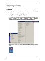
Accessing Element Manager Configuration
1. To access the Business Element Manager application from the Start
Menu,
navigate
to
Start,
Programs,
Avaya,
Business
Communications Manager, and Business Element Manager.
2. Alternatively, double-click on the Business Element Manager desktop
icon.
6
NN40011-007 Issue 1.2 BCM Rls 6.0
Telephony Services
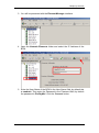
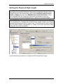
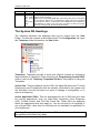
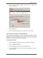
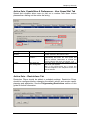
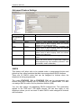
3. You will be presented with the Element Manager interface.
4. Open the Network Elements folder and select the IP Address of the
BCM.
5. Enter the User Name of the BCM in the User Name field, by default this
is nnadmin. Then enter the Password in the Password field, by default
the password is PlsChgMe!. Click the Connect button.
NN40011-007 Issue 1.2 BCM Rls 6.0
7
Telephony Services
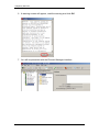
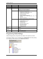
6. A warning screen will appear, read the warning and click OK.
7. You will be presented with the Element Manager interface.
8
NN40011-007 Issue 1.2 BCM Rls 6.0
Telephony Services
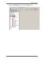
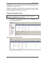
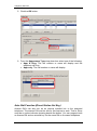
8. Select the Configuration tab, open up the Telephony tree.
NN40011-007 Issue 1.2 BCM Rls 6.0
9
Telephony Services
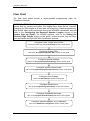
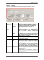
Flow Chart
The flow chart below shows a recommended programming order for
Telephony Services.
WARNING BCM450: Before commencing any Telephony programming,
ensure that the private and public DN lengths have been set as required.
Changing the DN lengths at a later date will erase any related programming.
This should have been performed during the BCM450 initialisation process
(refer to the Configuring the Received Number Lengths section of the
System Start Up Guide). For BCM50 systems, refer to the Setting the
Received Digit Length section of this guide, as this process may not have
been performed during the BCM50 Initialisation process.
Configure Lines, Loops, and Routes:
refer to the Lines, and also Call Routing sections of this guide.
Configure System DN’s:
refer to the Programming System DN’s section of this guide.
Configure general settings:
refer to the Programming Global Settings section of this guide.
Configure System Speed Dials:
refer to the Programming System Speed Dials section of this guide.
Configure Hunt Groups:
refer to the Hunt Groups section of this guide.
Configure Restrictions:
refer to the Programming Restrictions section of this guide.
Configure Scheduled Services:
refer to the Program Scheduled Services section of this guide.
Configure optional features, e.g. Hospitality:
refer to the Additional Configuration section of this guide.
10
NN40011-007 Issue 1.2 BCM Rls 6.0
Telephony Services
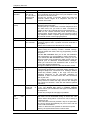
Setting the Received Digit Length
Note BCM450: The public and private Received Number Lengths should
have been set during the Telephony Resources configuration section of the
BCM450 System Start Up process (refer to the Configuring the Received
Number Lengths section of the BCM450 System Start Up Guide). If they
are configured after the Telephony Resources configuration, then any
previous Received Number assignments to Target Lines may be erased.
Note BCM50: The Received Digit Length should be set prior to any Target
Line programming. Changing the Received Digit Length erases any existing
received digits programmed for Target Lines. If the Received Number Lengths
and Received Number assignments to Target Lines have previously been
configured, then skip this section.
Use the following procedure to configure the Received Digit Length.
NN40011-007 Issue 1.2 BCM Rls 6.0
11
Telephony Services
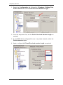
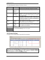
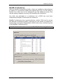
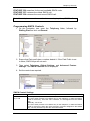
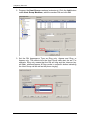
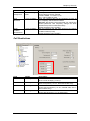
1. Select the Configuration tab followed by Telephony, Dialling Plan,
Public Network and select Public Received Number Length.
2. From the drop down list, set the Public Received Number length as
required.
3. If your BCM will be configured for use in a private network, select the
Private Network option.
4. Again, configure the Private Received number length as required.
12
NN40011-007 Issue 1.2 BCM Rls 6.0
Telephony Services
Lines
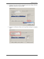
Configuring Lines
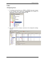
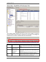
1. To configure physical lines (e.g. ISDN2 or ISDN30 channels) navigate
to the following path: Select the Configuration tab followed by
Telephony, Lines and Active Physical Lines.
2. Next, select the line to configure, and enter in the configuration settings
required.
NN40011-007 Issue 1.2 BCM Rls 6.0
13
Telephony Services
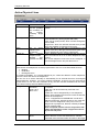
Active Physical Lines
Attribute
Line
Trunk Type
Name
Control set
Value
This list contains
all the possible
line numbers for
the
system,
including target
lines.
Loop, PRI, VoIP
Up to seven
alphanumeric
characters
DN
<control
telephone DN>
Default:
221
(default start DN)
Description
Configure only those lines that are active on the
system.
There are three main categories of lines:
PSTN-based lines: (analog, digital, PRI, BRI)
Voice over IP (VoIP) trunks, which connect through the
LAN or WAN.
Target lines, which are internal channels that provide
direct dial capability for PRI and VoIP trunks.
Identify the line in a way that is meaningful to your
system, such as by the type of line and line pool or the
DN it is attached to in the case of Target lines.
Enter a telephone DN for a telephone that you want to
use to turn service off or on for other telephones using
this line.
The control telephone must have the line assigned, or
must be assigned to the line pool the line is in.
Tips
External lines and telephones must be programmed to use one of the Scheduled Services:
Ringing
Restriction
Routing Services.
For maximum flexibility, it is recommended that you create two different control telephones,
one for the lines and one for the telephones.
You can turn on a service manually or automatically for all external lines from an assigned
control telephone. However, you cannot combine schedules. A service can only be active as
normal service or one of the six schedules at any one time. Several schedules can be active
at one time, but they must use different services.
Line type
Public
Define how the line is used in relation to other lines in
Private to:
the system.
Pool A to O,
Public line: can be accessed by more than one
Bloc A to F
telephone.
Private line: can be assigned only to one telephone
and the prime telephone for that line. Enter the internal
number of the telephone.
Pool A - O (digital lines and BRI/BLOC-A to BLOC-F
(PRI and VoIP lines): assigns the line to one of the line
pools. If a line is assigned to a line pool, but is not
assigned to any telephone, that line is directly available
only for outgoing calls.
BLOC line pools must be used in conjunction with
routes and destination codes. Target lines cannot
be put into line pools.
Prime set
14
DN:
None
Assign a telephone to provide backup answering for
calls on the line. For an Auto Answer line, calls are
redirected if the received number is invalid or the target
NN40011-007 Issue 1.2 BCM Rls 6.0
Telephony Services
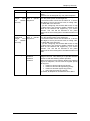
Attribute
Value
Pub Received #
(Target
lines
and
DASS2
lines only
Digits associated
with a specific
target line
Private
Received #
(Target
lines
and
DASS2
lines only)
Digits associated
with a specific
target line
Distinct ring
None
Pattern 2
Pattern 3
Pattern 4
NN40011-007 Issue 1.2 BCM Rls 6.0
Description
line is busy, and if the If busy parameter is set To
prime.
Each line can be assigned only one prime telephone
Specify the digits the system will use to identify a call
from the public system to this target line.
A received number cannot be the same as, or be the
start digits, of a line pool access code, a routing code,
the DISA DN or the Auto DN.
If you are configuring auto-answer BRI trunks to map
to target lines, the received number should be the
same as the Network DN supplied by your service
provider. The call will be directed to the prime
telephone for the incoming line if the Network DN is not
used
Specify the digits the system will use to identify a call
from the private system to this target line.
A received number cannot be the same as, or be the
start digits, of a line pool access code, a routing code,
the DISA DN or the Auto DN.
If you are configuring auto-answer BRI trunks to map
to target lines, the received number should be the
same as the Network DN supplied by your service
provider. The call will be directed to the prime
telephone for the incoming line if the Network DN is not
used.
Choose the distinctive ring pattern that you want to
assign to the line. This allows you to provide selective
service to calls with differing answer priorities.
When more than one line with the distinct ring settings
rings at a telephone, the line with the highest priority
will ring first.
Pattern 4 has the highest ring priority
Pattern 3 has second highest ring priority
Pattern 2 has third highest ring priority
None has the lowest ring priority.
By default, all telephones and lines are set to None
15
Telephony Services
Lines - Properties Tab
The line properties that appear here are dependent on the lines to be
configured.
Attribute
Value
Description
Legend: Loop = analog/digital loop; GS = ground start; DID = DID; E&M = E&M; BRI =
BRI; DPNSS = DPNSS; VoIP = VoIP; TL = Target and DASS2. Note: PRI fields are all
included under the main screen
Define how the line is used in relation to other lines in the
Trunk
Loop
system.
mode
Unspr
• Public line: can be accessed by more than one telephone.
Supervised
• Private line: can be assigned only to one telephone and the
*Earth calling
prime telephone for that line. Enter the internal number of the
*Loop guarded
*Loop unguarded telephone.
• Pool A - O/bloc…: assigns the line to one of the 15 line
pools. If a line is assigned to a line pool, but is not assigned to
any telephone, that line is available only for outgoing calls.
PRI lines are set to pool blocb by default.
Dial mode
Loop GS
Pulse
Tone
Line Tuning
Digit
Loop (analog
only)
None, 0 - 9
Loop (analog
only)
Loss
Package
DID E&M
Specify whether the system uses dual tone multi-frequency
(DTMF) or pulse signalling on the trunk.
Tone does not appear if Signalling is set to Immediate
(T1 DID &T1 E&M trunk types only).
Default = 1
Select the appropriate loss/gain and impedance settings for
each line.
Short CO
Medium CO
Long CO
Short PBX
Long PBX
Impedance
(Ohms)
16
Loop (analog
only)
600 ohm
900 ohm
The GATM can be set to a specific impedance level.
NN40011-007 Issue 1.2 BCM Rls 6.0
Telephony Services
Attribute
Value
Description
Signalling
DID
WinkStart
Immediate
DelayDial
*Gain
Normal
High
Link at CO
Loop (analog
only)
check box
Link time
Loop (analog
only)
time
Loop (analog
only)
E&M
Select the signal type for the line. The immediate setting
does not appear for T1 E&M or T1 DID trunks connected to
a DTM if the Dial mode is set to tone.
Make sure that this matches the signal type programmed
for the trunk at the other switch.
E&M
Set the level of gain for the channel.
*E&M trunks only. T1 E&M trunks do not have this field.
Some exchanges respond to a Link signal (FEATURE 71)
by providing an alternative line for making outgoing calls.
Enabling Link at CO causes the system to apply the
restrictions on outgoing calls to the digits dialled after the
Link signal. As well, the call on the alternative line is
subject to all restrictions.
Disabling Link at CO prevents a Link signal from resetting
the BCM restrictions in cases where the host exchange
does not provide an alternative line.
Link at CO is enabled.
The duration of the on-hook signal sent when the user
activates the Link feature.
This field tells the system to either detect a dial tone before
sending the dial string, or to wait a period of time and then
send the dial string.
Dial tone
(detect
delay)
Detect
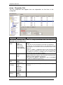
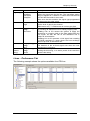
Lines – Preferences Tab
The following example shows the options available for a PRI line:
NN40011-007 Issue 1.2 BCM Rls 6.0
17
Telephony Services
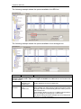
The following example shows the options available for a BRI line:
The following example shows the options available for an analogue line
Attribute
Value
Description
Legend: Loop = analog/digital loop; GS = ground start; DID = DID; E&M = E&M; BRI = BRI;
DPNSS = DPNSS; VoIP = VoIP; TL = Target and DASS2. Note: PRI fields are all included under
the main screen
Auto privacy Loop GS DID
Define whether one BCM user can select a line in use at
E&M BRI VoIP
another telephone to join an existing call.
<check box>
Full
Loop BRI DPNSS Enables or disables Full autohold.
autohold
VoIP
When enabled, if a caller selects an idle line but does not dial
<check box>
any digits, that line is automatically placed on hold if you then
select another line.
Full autohold is always in place for T1 E&M trunks because it
has no meaning for incoming-only T1 DID trunks.
The default setting should be changed only if Full autohold is
required for a specific application.
18
NN40011-007 Issue 1.2 BCM Rls 6.0
Telephony Services
Attribute
Aux. ringer
Value
Loop GS DID
E&M BRI DPNSS
VoIP TL
<check box>
ANI Number
DID E&M
<check box>
DNIS
Number
E&M
<check box>
Distinct
Rings in
use
Answer
mode
<read-only>
Answer with
DISA
Loop GS E&M
BRI
<check box>
If busy
TL
To Prime
Busy Tone
Voice
Message
Center
Loop GS DID
E&M BRI DPNSS
VoIP TL
Center 1 Center 5
Loop GS DID
E&M
<dial string>
Redirect to
Loop GS E&M
BRI DPNSS
Manual
Auto
Description
Turn the auxiliary ringer on or off for all telephones using this
line. When programmed on a line, the auxiliary ringer will ring
every time a call is received.
Note: When programmed only on a telephone, no ring occurs
for a transferred call. An auxiliary ringer can also be
programmed in Services to ring for a line placed into a
scheduled Ringing service.
Define whether the telephone number of the caller will be
shown for this line.
For T1 E&M and T1 DID trunks connected to a DTM, this
setting only appears if Signaling is set to WinkStart.
The central office must deliver ANI/DNIS in DTMF mode. No
additional equipment is required.
Defines whether the digits dialed by an external caller on this
Line will be shown. For T1 E&M trunks connected to a DTM,
this setting only appears if Signaling is set to WinkStart and
Answer mode is set to Manual.
Indicates if a special ring has been assigned.
Define whether a trunk is manual or automatic answer.
Auto answer mode allows the trunk to be a shared resource
by the system telephones. This shared resource is created
through routing to target lines or using DISA.
For auto answer trunks being used to allow remote call-in from
system users, the trunk can be configured to answer with a
straight dial tone, if DISA has not been enabled. It can also be
configured to answer with a stuttered dial tone if DISA is
enabled and the caller is expected to enter a CoS password.
The CoS password defines which system features the caller is
permitted to access.
Manual answer trunks are assigned to one or more
telephones.
The assigned telephones exclusively own the line.
Note: You require Disconnect supervision on the line if loop
start trunks are to operate in auto-answer mode.
Define whether the system prompts a caller for a six-digit
class of service (CoS) password. This setting appears for T1
loop start, T1 E&M lines that have auto-answer mode, and
analog trunks. Set this option to No for T1 E&M lines on a
private network that have auto-answer mode.
Define whether a caller receives a busy tone or the call
forwards to the prime telephone when the target line is busy.
Busy tone only works for PRI trunks.
Tips: The duration of an open switch interval (OSI) before
BCM disconnects a call is programmed by the Disconnect
timer setting.
If this line connects to a remote voicemail, either through the
private network or at the Central Office, indicate which Center
number has been configured with the contact number. The
system calls that number to check voicemail messages when
a message indicator is presented to a telephone.
Enter a dial string (including destination code) to redirect the
line to an external telephone, such as a call attendant on
another system.
If you want to stop redirection, you need to delete the dial
string and allow the record to update.
Warning: If the dial string is set up, the line will immediately be
redirected out of the system not ringing any telephone.
NN40011-007 Issue 1.2 BCM Rls 6.0
19
Telephony Services
Attribute
Value
Description
Warning: Enable modules. If you disabled any trunk media bay modules prior to performing
programming, enable them now to ensure your system will function properly.
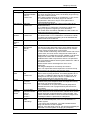
Target Lines (DID)
Target Lines DID (Direct Inward Dial) lines are assigned directly to telephones
and support a range of Public DN’s as a line assignment. Each line is mapped
directly to a telephone or group. They cannot be used for outgoing calls.
The following example shows the options available for a Target Line:
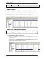
Target Lines - Public Received Number
Note: When configuring Target Lines the Received numbers should be set.
These are the digits sent from the exchange (Public) of from other switches
(Private) if the BCM is in a network.
To enter a received number for a Target Line:
1. Open the Telephony folder then open the Lines folder and select
Target Lines.
2. Double click on the Public/Private Received number field as required
and enter the received number for the line.
20
NN40011-007 Issue 1.2 BCM Rls 6.0
Telephony Services
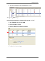
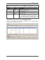
3. The received number will then be displayed for the line.
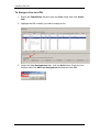
Configuring BRI Loops
Use the following procedure to configure the BRI loop type, i.e. S or T.
1. Open Telephony, then click on Loops.
2. Select the Loop to configure.
3. Select the Type from the option box provided.
4. Configure the loop accordingly.
NN40011-007 Issue 1.2 BCM Rls 6.0
21
Telephony Services
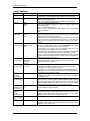
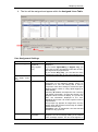
Loop Settings
Attribute
Loop
Value
<X01-X04>
Type
T
S
Protocol
Euro
QSIG
NI-2
Sampling (Sloops only)
Adaptive
Fixed
N/A
ONN blocking
(T-Loops only)
Suppression
Service code
N/A
Clock source
(T Loops only)
Primary External
Secondary
External
Internal
S-T user
T-T user
Protocol Type
(T-Loops only)
Overlap:
receiving
(T-Loops only)
SPID Digits
(T-Loops only)
<check box>
SPID: Number
of B-Channels
(T-Loops only)
Enable
DPacket
Service
(T-Loops only)
Associated
loop (T-Loops
only)
TEI
1
2
22
<digits>
<check box>
<X01-X04>
<digits>
bit
Description
Each BRI module supports four loops (eight lines for T-loop
programming). The BCM50b models support 2 on board loops.
This setting defines whether the loop supports trunks (T-loop) or
device connections (S-loop).
Note: This variable may be different for different market profiles.
Select the appropriate ISDN protocol.
The values displayed depend on both the market profile and
software keycodes.
Euro - ETSI ISDN standard
QSIG - also an ETSI standard. Only appears if the ETSI QSIG
keycode is loaded.
NI-2
Select a sampling rate for the S-loop.
Fixed: two or more S-interface devices use the loop, and the length
of the loop is less than 200 m (650 ft.).
Adaptive: two or more S-interface devices use the loop, and the
length of the loop is greater than 200 m (650 ft.). If one device is
using the loop, the length of the loop can be a maximum of 1000 m
(3230 ft)
Set the Outgoing Name and Number (ONN) Blocking.
When you activate ONN, a user can press FEATURE 819 to block
the outgoing name and number on a per call basis.
Programming note: Ensure that all telephones that have this
feature available are assigned valid OLI numbers.
Suppression bit: the system flags the call to the Central Office (CO)
so that the name and number is not sent to the person you call.
Service code: VSC digits are dialled out before the called number
to activate ONN at the central office. These codes are supplied by
your service provider for the lines.
Primary External - uses clock from PSTN
Secondary External - used if system has more than one Loop
Internal - uses clock on BCM
When set to S-T user, the BRI connection to the public network is
treated like a line which appears on a set and is the termination
end point for the call (Key system model).
When set to T-T user, the BRI connection to the public network is
treated like a trunk, which allows tandems to other switches without
first answering the call (PBX model).
Supports target lines in markets which use Overlap receiving
signalling on the BRI trunks. Overlap receiving must be configured
for each BRI loop.
NA only. Supplied by your service provider. System running with
North American country profiles support additional BRI services
offered by ISDN service providers and defined by network service
profile identifiers (SPID). The SPID allows you to enter a network
connection that provides a path for voice or data services.
NA BRI loops can support two B-channels. The SPID may be the
same or different for the channels.
This panel enables you to configure D-Packet Service to T-loops.
You must have both T-loops and S-loops configured on the same
module to allow this feature. Enable this service, only if you are
installing devices that require this type of service.
Shows the associated S-Loop.
These entries identify up to eight terminal identifiers for the devices
assigned to the S-loops. Your BRI service provider supplies these
numbers, if they are required.
NN40011-007 Issue 1.2 BCM Rls 6.0
Telephony Services
Call Routing
Call Routing decides what path an outgoing call takes using the digits that are
dialed. It is sometimes called Automatic Route Selection (ARS).
When you select an internal line and dial, the system checks the numbers you
enter against the routing tables. If the number you dial starts with a
destination code, the system uses the line pool and dials out digits specified
by the route assigned to that destination code, and then dials the rest of the
number that you dialed.
Routing service replaces a number of manual tasks, including:
entering a line pool code
dialing an access code for a long distance carrier
deciding which line pool to use according to the time and day
The following example shows how to build a route to a remote office site. The
objective is to access any DN (extension) at the remote site, by dialing a
minimum of digits.
The remote site has a 4-digit DN/DDI length, and the start DN is 2000. The
main telephone number for the remote site is 0161 235 2000. Using the
following example it will be possible to dial any DN at the remote site by
dialing 82xxx, where xxx is any DN/DDI number.
1. From the Configuration tab select Telephony, and then Dialing Plan.
Click on Routing.
NN40011-007 Issue 1.2 BCM Rls 6.0
23
Telephony Services
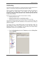
2. Click on Add. Enter up to three digits for the routing code (001-999)
and click OK.
3. Click on the route you have just created. Select a pool to use in Use
Pool drop down, e.g. BlocB.
4. Select the Service Type option and set the Service Type as required.
24
NN40011-007 Issue 1.2 BCM Rls 6.0
Telephony Services
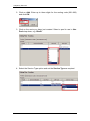
5. For this example we will have to enter part of the desired number string
in the External number field so that it is passed on to the exchange
6. Click on the Destination Codes tab and click on Add.
Note: Destination code 9 is automatically assigned against route 000. To
use destination code 9 against another route e.g. 001, it may be necessary
to delete destination code 9, add it again, and then assign route 001.
7. In this example we shall use destination code 82. Click OK.
NN40011-007 Issue 1.2 BCM Rls 6.0
25
Telephony Services
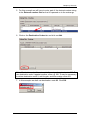
8. Select the destination code you have just created (e.g. 82) and click on
a Normal Route field for the destination code you have created. Type in
the route to use (e.g. 002), and state how many digits of the destination
code to absorb.
9. In this example we only want to absorb 1 digit, i.e. 8 so that the 2 can
be passed with the other digits in the External Number field. Therefore,
entering 82013 on a handset results in 0161 235 2013 being dialed.
Note: The destination codes must not conflict with the following:
park prefix, external code, direct dial digit, Auto DN, DISA DN, Private access
code, line pool codes, telephone DN, hunt group DN, target line received
digits, other routing codes
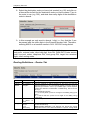
Routing Definitions – Routes Tab
Attribute
Route
External
Number
Value
<001-999>
<a maximum of
24 digits>
Use Pool
Pool A to Pool O
or
BlocA
to
BlocF
Public
Private
Local
(Subscriber)
DN Type
26
Description
This number is unique to each route.
Enter the external or dial-out number for the route you want the
assigned telephone to use. The external number is a digit or group of
digits that get inserted in front of your dialled digits. If all the required
numbers are defined in the destination code/dial string, this box can be
left empty.
Optional dial string entries:
P = 1.5 second pause (counts as one digit in the dialling string) (F78
telset)
DT = wait for dial tone (counts as two digits in the dialling string)
(F804 telset)
Select a line pool for the route.
This setting tells the system what type of line protocol the route uses to
process the dial string.
MCDN private networks: Local, National and Special are special
designators used to route calls from Meridian 1 systems, through BCM
NN40011-007 Issue 1.2 BCM Rls 6.0
Telephony Services
Attribute
Value
National
Special
(International)
Service
Type
Service ID
Overlap
None
<digits>
Note:
Description
systems, out to the public network. The codes for these settings are
defined under Telephony > Dialling plan > General > Private Networks
tab. When the BCM receives outgoing calls from the Meridian 1, it
recognizes the call type and appends the appropriate access code to
the Meridian dial string.
This code then matches to a route that uses the same DN type,
passing the call along, either to another node (the route would have
the same DN type) or to the public network (the route would have a
Public DN type), depending on the routing information.
Displays for PRI lines. Overlap can result send dial tome to the user.
If you choose a service, type in the identification number for the
service.
Outgoing call display: If you have the trunks set up to send called number information,
and the DN type is set to anything, except Private, the system sends the Public OLI
number you specified under line programming. If the DN type is set to Private, the system
sends the Private OLI number. (Line Access tab).
Actions:
Add
1. Under the routes table, click Add.
2. Enter a route number in the dialog box.
3. Click OK to save the new route.
Delete
1. On the routes table, select the route you want to delete.
2. In the Routes panel, click Delete.
3. Click OK.
Modifying
Warning: Modifying some route settings may result in dropped calls. Ensure that you
routes:
modify the destination codes Absorbed Length setting, if required, if you add or change the
External Number entry.
Changing the Use Pool or DN Types/Service Types values will result in dropped calls if the
lines in the line pool do not support the DN/Service Type selected.
1. On the routes table, select the route you want to change.
2. Click the field you want to change for that route and enter the new value.
3. Press Tab on your keyboard to save the change.
Routing Definitions – Destination Codes Tab
Attribute
Destination
Code
Value
<max. 12 digits>
Normal
Route
Absorbed
Length
Wild Card 0
-9
<configured route
#>
All, None, 1-X
Included,
Excluded,
Unavailable
Description
This number precedes a telephone number to tell the system where
the call needs to be routed. An A in the destination code represents
an, any character designation. The A code is a wildcard.
This is the route that the system will use when the destination code
is added to the dial string.
This indicates how much of the destination code gets removed
before the system sends the dial string to the network.
If you enter the wild card character A at the end of a destination
code, then the following applies:
Included: This number can be dialled as part of the destination
code.
Excluded: This number will not be accepted as part of a destination
code string because it is already used in the system.
NN40011-007 Issue 1.2 BCM Rls 6.0
27
Telephony Services
Attribute
Actions
Add
Delete
Value
Description
Unavailable: This number is already defined in another destination
code and cannot be used.
1. Under the Destination Codes table, click Add.
2. Enter the new destination code.
3. Click OK to save the route settings.
4. On the Destination Codes table, select the fields beside the route you just created, and
modify them, as required.
5. Test the route.
1. On the Destination Codes table, select the destination code you want to delete.
2. In the Destination Codes pane, click Delete.
3. Click OK.
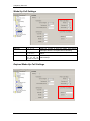
Routing Definitions – Second Dial Tone Tab (PRI Lines)
This feature provides dial tone for outgoing calls on any PRI line, based on
the digits dialed. Digits dialed must match an entry in the second dial tone
table to enable a second dial tone. Dial tone occurs on the line until another
digit is dialed, a timeout occurs, or the user hangs up.
Up to 10 separate entries can be stored in the second dial tone table. The
maximum digit length for each entry is four.
Each entry must be unique and cannot conflict with:
Internal DN's
Hunt Group DN’s
DISA DN’s
Auto DN’s
Target Line DN’s
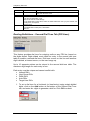
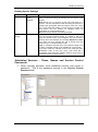
1. To set a dial tone for a line/trunk (or lines/trunks) using certain dialled
digits, click on the Add button at the bottom of the Second Dial Tone
tab, and enter the digits to generate a dial for. Click OK to submit.
28
NN40011-007 Issue 1.2 BCM Rls 6.0
Telephony Services
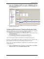
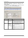
Configuring Overflow Routing
If all the lines used by a route specified by a destination code are busy when a
call is made, you can program other routes that the system automatically
moves the calls to or you can allow the call to overflow directly to the Normal
route schedule (usually the most expensive route). However, this only takes
effect if an active schedule is applied to the line. Overflow routing is not
available in Normal mode.
You must create overflow routes for each destination code for which you want
to allow overflow routing.
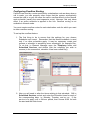
To set up the overflow feature:
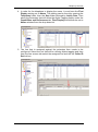
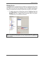
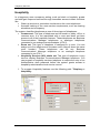
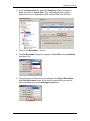
1. The first thing to do is ensure that the settings for your chosen
Schedules are correct. Remember that the Normal schedule is used
only if no other schedules apply. It may be necessary create and
rename a schedule to something more meaningful, for example Day.
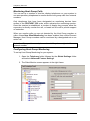
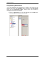
To do this, in Element Manager open the Telephony folder and
Scheduled Services, and double click the schedule you wish to
rename (in the screenshot, schedule 4 has been called Day).
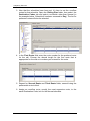
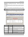
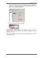
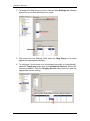
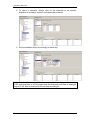
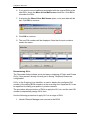
2. Now you will need to alter the times relating to that schedule. Still in
Scheduled Services, select and enter the Schedule times for each of
the corresponding days, i.e. Monday, Tuesday, and so on. If the
service is to apply over a 24-hour period, then choose 0100 for both
the start and the finish times.
NN40011-007 Issue 1.2 BCM Rls 6.0
29
Telephony Services
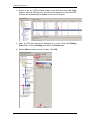
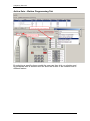
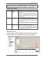
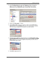
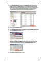
3. Now that the schedules have been set, it’s time to set the overflow
routes for that schedule. Open the Dialing Plan folder, then select the
Destination Codes tab and select a schedule other than Normal (in
the example below, Schedule 4 has been renamed to Day). The list for
preferred routes will also be selected.
4. In the First Route field enter the route number for the preferred route
for the call. Choose the absorb length for the first route that is
appropriate for the dial out numbers you entered for the route.
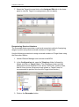
5. Repeat for Second Route and Third Route fields; second being the
preferential route to third.
6. Assign an overflow route, usually the most expensive route, to the
same Destination Code, but for the Normal schedule.
30
NN40011-007 Issue 1.2 BCM Rls 6.0
Telephony Services
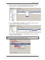
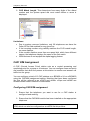
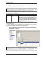
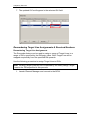
7. Open the Telephony folder and select Scheduled services,
<preferred route schedule>, choose auto for Service Setting, and
tick the Overflow box.
8. Set the Routing Svc field to Auto to ensure that this service adheres to
the times set previously.
Configuring PRI Pool Access, Routes and Destination Codes
Access to a PRI line pool must be done by assigning a Destination Code and
associated Route. An overview of this configuration would be:
PRI lines can be assigned to pools BlocA to BlocF (VoIP trunks will use
one of those Bloc’s).
You assign the PRI line pool to a route (e.g. Route 001).
You then assign the Route to a Destination Code (e.g. 9).
Thus in this example, digit 9 can be dialled to access the PRI line pool.
All lines in a PRI module must reside on the same line pool. However, lines
from more than one PRI module can belong in the same line pool.
Ensure that the required Destination Code does not conflict with any other
access code etc.
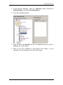
1. Open the Telephony folder, followed by the Lines folder, select Active
Physical Lines, and then Enabled Physical Lines.
NN40011-007 Issue 1.2 BCM Rls 6.0
31
Telephony Services
2. Select a line on a PRI module. Open a line and from the Line Type
options, select a PRI line pool. All other lines attached to the same PRI
module will automatically be added to the same PRI pool.
3. Next, the PRI pool should be assigned to a route. Open the Dialling
Plan folder, click on Routing and select the Routes tab.
4. Select Add and enter a route number. Click OK.
32
NN40011-007 Issue 1.2 BCM Rls 6.0
Telephony Services
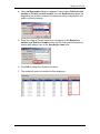
5. Select the route you have just created, and ensure that it uses the
required line pool. In this example BlocB has been selected.
6. Set the Service Type to Overlap. This will give dial tone when
accessing the route (applicable in some regions).
7. Select the Destination Code tab. Select Add and enter the required
Destination Code. Click OK.
Note: Route 000 which cannot be changed from using Pool A. Create another
route e.g. 001, and apply this to Destination Code 9.
NN40011-007 Issue 1.2 BCM Rls 6.0
33
Telephony Services
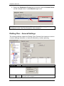
8. Select the Destination Codes tab and set the required Normal Route
(in this example route 1) and Absorb length to all.
Note: For an extension to use the PRI route, the PRI pool (e.g. Blocb) must
be assigned under Line Pool Access for that extension.
Dialling Plan – General Settings
The settings defined under the Dialing Plans General link determine various
common settings that affect, or that are affected by, number planning.
Attribute
Value
Global Settings
Description
DN length
(intercom)
This is the length of the locally-dialled telephones. This field is set when
the system is first configured.
34
(2 to 7)
Undefined
NN40011-007 Issue 1.2 BCM Rls 6.0
Telephony Services
Attribute
Value
Dialing
3, 4, 5, 8,
timeout
10, 15
Access Codes
Park prefix
None
<one-digit
number>
External
code
None
<one-digit
number>
Description
Warning: If this system is part of a private network, ensure that this value
is compatible with the network requirements.
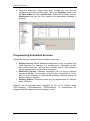
This value is mirrored in the Private Received Number Length field for
target lines.
Note: If the DN length is changed, it will cause VM/CC to be defaulted
in order to work properly.
This is the maximum time allowed between user dialpad entries, before the
system considers the dialstring complete. Default = 4.
The Park prefix is the first digit of the call park retrieval code that a user
enters to retrieve a parked call. If the Park prefix is set to None, calls
cannot be parked.
SWCA note: If this field is set to None, the system-wide call appearance
(SWCA) feature will not work.
The External code setting allows you to assign the external line access
code for 7100 and 7000 digital phones and analog telephones attached to
ATA 2s or to analog modules to access external lines. Note: Model 7000
phones are supported in Europe only. When the caller picks up the
handset, the system tone sounds. The caller then enters this number to
access an external line. Note: This number is overridden by line pool or
starting with the same digit(s).
Change DN
Change DN
<button>
Click to re-identify a DN.
Note: This method is faster than re-identifying the DN’s under
Configuration > Telephony > Dialling Plan > DN’s.
Direct Dial
Direct Dial
digit
None
<one-digit
number>
Define Direct Dial Sets
The Direct dial digit setting allows you to specify a single system-wide digit
to call a direct dial telephone.
Set
Type
This tags the telephone to the system.
This is the type of number for the direct-dial set.
Internal DN
<1-5>
Internal
External
None
DN
External
<external
The DN number of the telephone to be designated as the direct dial set.
(Internal sets).
The actual phone number, including destination codes, of the direct dial
NN40011-007 Issue 1.2 BCM Rls 6.0
35
Telephony Services
Attribute
No.
Facility
Value
dial string>
Line
Pool (A-O)
Use prime
line
Use routing
table
Description
set (External sets).
The facility to be used to route the call to a direct dial set that you define
with an external number.
Note: If you choose Use prime line, ensure that prime line is not assigned
to the intercom buttons for your telephones. When prime line is assigned
as an intercom button, it chooses the first available line pool assigned to
the telephone to make a call. If this line pool does not have the correct
lines for routing the call, the direct dial call will fail.
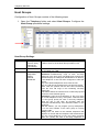
The System DN Headings
The following describes the headings that can be viewed from the Sets
Folder. To view the contents of this folder select The Configuration tab, open
the Telephony folder followed by the Sets folder.
Templates: Templates provide a quick and effective method of configuring
large numbers of extensions. After reviewing the Programming System DN’s
section, refer to the Telephony Templates Guide for information on using the
Templates.
Active Sets: This list displays only the DN’s for digital (M-series and T-series
telephones) and IP telephones that are actually connected to the system and
are activated. Use this list when you want to change a configuration, or to
remove a telephone.
Active Application DN’s: This list segregates the list of DN’s that are used
for running applications, such as Voice Mail, Interactive Voice Response
(IVR), Contact Center, and Find Me Follow Me. These DN’s are assigned
within the applications that they apply to. You do not need to do anything to
any of these DN’s, other than to note they are not available for application to
your telephones.
Warning: Changing the settings on these DN’s could cause malfunctions in
the applications to which they apply.
36
NN40011-007 Issue 1.2 BCM Rls 6.0
Telephony Services
Inactive DN’s: lists all available DN’s within the BCM Numbering range, any
active DN will not appear in this list.
All DN’s: This list displays all possible DN’s, regardless of whether a station
module is configured to activate them or not. This list begins with the Start DN
that was defined when the system was initialized.
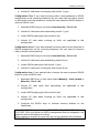
Programming System DN’s
Note: If programming a large number of DN’s with the same settings, you
may find it more convenient to use Telephony Templates. Refer to the
Telephony Templates guide for instructions.
1. To program connected extensions/DN’s, open the Telephony folder
and select Sets, Active Sets.
Active Sets - Line Access Tab
NN40011-007 Issue 1.2 BCM Rls 6.0
37
Telephony Services
The Line Access tab displays the below columns.
Attribute
DN
Value
Numeric
Model
Avaya digital
set
ISDN and
DECT
up to seven
alphanumeric
characters
Name
Port
<port number>
Private
number
OLI
Public
number
OLI
Fwd no answer
to
Forward Delay
Fwd Busy
Fwd All
up to 24 digits
(10 digits,
North
America
<up to 24 digits
(10 digits,
North
America)>
Description
The active extensions on the system. The length of which
is derived from the DN length configured on the BCM
The model or component assigned against the DN.
Use this field to provide a more specific description of the
telephone, such as the last name of the user or the
location, or the actual extension number if it is different
than the DN number.
This number indicates the port number that this device is
connected to, if the device is active, or which port the
device would connect to, if the device is currently inactive.
This field is not available or not shown for Companion and
ISDN and DECT device records.
Define the originating line identification number (OLI)
which appears on the telephone (across a private
network) being called from this telephone
Define the originating line identification number (OLI)
which appears on the telephone (across a public network)
being called from this telephone
See Call Forwards Settings section of this guide
Call Forward Settings
Configure Call Forward options required for the extension.
Note: When setting Call Forwards for Contact Center extensions, always
ensure that that the Fwd Delay is set higher than the Transfer Callback
Timeout settings in Feature Settings. If the extension is used for Contact
Center purposes do not set the Fwd Busy setting.
38
NN40011-007 Issue 1.2 BCM Rls 6.0
Telephony Services
Note: A common destination for Call Forwards is the Voicemail DN, i.e. send
to mailbox. This can be found by entering F985 on a handset with a display.
Attribute
Fwd no answer to
Forward Delay
Fwd Busy
Fwd All
Values
Up to 24
digits
2,3,4,6,10
Up to 24
digits
Any number
Description
Enter the number to which you want to redirect
Unanswered incoming calls
Define the number of rings before the system forwards
an unanswered call
Redirect Incoming Calls when the telephone is busy
with another call
Same as Feature 4 used at a phone. When active all
calls to this telephone are forwarded to this telephone. If
you are forwarding all calls to a remote location, ensure
that you include the required destination/access codes.
A user can press Feature #4 to cancel this feature.
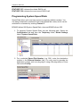
Active Sets, Line Access - Line Assignment Tab
Allows you to assign lines that will be available for the extension. Both
incoming DDI, Physical and VoIP lines.
NN40011-007 Issue 1.2 BCM Rls 6.0
39
Telephony Services
To Assign a Line to a DN:
1. Select the Capabilities tab and open the Sets folder and click Active
sets.
2. Highlight the DN to which you wish to assign a line.
3. Under the Line Assignments tab, click the Add button. Enter the line
number within the Add Line Assignment window and click OK.
40
NN40011-007 Issue 1.2 BCM Rls 6.0
Telephony Services
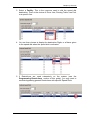
4. The line will be assigned and appear within the Assigned Lines Table.
Line Assignment Settings
Attribute
Appearance type
Values
Ring only,
Appear &
Ring, Appear
only
Appearances
(for target lines,
only)
Caller ID Set
<digit>
Y or N Checkbox
Choosing Y enables the telephone to display call
information on the telephone display, when it is
available for a call. This setting also is used in
conjunction with other settings to create the alpha
tagging feature. Refer to Using alpha tagging for
name display.
Choosing N disables the telephone from receiving
call display information. Choose this setting if the
telephone does not have a display, or if you do not
want call information displayed to the user.
Disabling this function can reduce system resource
requirements.
This prompt only appears for target lines, and any
analog lines that provide CLID through an ASM8+
(North America only).
Limitation: Only 30 telephones can have this field
enabled for any given line.
Vmsg set
Y or N
Checkbox
Select whether an indicator shows on the
telephone for voice message waiting to an external
voice message system. The line must appear on
NN40011-007 Issue 1.2 BCM Rls 6.0
Description
Select how a call on this line shows on the
telephone.
If you choose Appear&Ring or Appear only, you
can have as many simultaneous DID calls as there
are target line key appearances.
If you choose Ring only, you can have as many
simultaneous DID calls as you have intercom keys.
Selects the number of appearances of a target line.
41
Telephony Services
Attribute
Values
Private Received #
(Target lines and
DASS2 lines only)
Digits associated
with a specific
target line
Pub Rx Number
(Target lines and
DASS2 lines only
Digits associated
with a specific
target line
Description
receiving telephone.
Specify the digits the system will use to identify a
call from the private system to this target line.
A received number cannot be the same as, or be
the start digits, of a line pool access code, a
routing code, the DISA DN or the Auto DN.
If you are configuring auto-answer BRI trunks to
map to target lines, the received number should be
the same as the Network DN supplied by your
service provider. The call will be directed to the
prime telephone for the incoming line if the
Network DN is not used.
Specify the digits the system will use to identify a
call from the public system to this target line.
A received number cannot be the same as, or be
the start digits, of a line pool access code, a
routing code, the DISA DN or the Auto DN.
If you are configuring auto-answer BRI trunks to
map to target lines, the received number should be
the same as the Network DN supplied by your
service provider. The call will be directed to the
prime telephone for the incoming line if the
Network DN is not used
Active Sets, Line Access - Line Pool Access Tab
The Line Pool Access tab allows you to define the line pools that the
telephone will be able to access. These shared pools of lines allow many
users to use fewer lines for connections where dedicated lines are not
practical or not desirable. If all lines in the pool are taken, the user receives a
busy signal.
To assign a Line Pool to an Extension:
1. Click the telephone DN to which you want to assign a line pool.
2. Click on the Line Pool Access tab.
3. Click the Add button.
42
NN40011-007 Issue 1.2 BCM Rls 6.0
Telephony Services
4. Enter a line pool identifier. <Digital - Pool A to O> or VOIP & PRI
<Block -A to Block-F>.
5. Click the OK button.
6. The line pool identifier appears under the Line Pool Access tab.
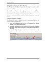
Active Sets, Line Access - Answer DNs Tab
You can program a telephone to provide automatic call alerting and call
answering for other telephones in the system. The DNs of the other
telephones are referred to as Answer DNs or answer keys. You can assign a
maximum number of 8 Answer DNs to a telephone.
Assigning Answer DNs
1. Click the telephone DN to which you want to assign an answer DN.
2. Click on the Answer DNs Tab.
3. Click the Add button located above the navigation tree.
4. In the Answer DN field, type in the DN for the telephone you want to
be able to answer.
NN40011-007 Issue 1.2 BCM Rls 6.0
43
Telephony Services
5. Click the OK button
6. From the Appearance Type drop down box select one of the following:
Appr & Ring: The call number or name will display and the
telephone will ring.
Appr only: The call number or name will display.
Auto Dial Function (Direct Station Set Key)
Answer DN’s can also act as an internal autodial link to the assigned
telephone. The answer DN must be idle for this feature to work. That is, there
must be no active indicator showing beside the button. You can program both
an Answer DN and an autodial key for the same DN on the same telephone.
44
NN40011-007 Issue 1.2 BCM Rls 6.0
Telephony Services
MeetMe Conferencing
With the MeetMe Conferencing facility, callers can establish a teleconference
by calling in to a specified number at an agreed-upon time. For this facility to
function one caller acts as the chairperson and has additional powers that
include starting, stopping, securing, and controlling the conference.
Any caller can participate in a conference, but a BCM user must have
chairperson privileges to chair/control a conference.
MeetMe Conferencing has a special directory number (DN) used to access
the Meet Me Conferencing feature. Although you can access a conference in
several ways, the system administrator should notify every conferencing user
of the MeetMe Conferencing DN.
Note: For further information see separate MeetMe Conferencing Guide.
NN40011-007 Issue 1.2 BCM Rls 6.0
45
Telephony Services
Active Sets - Capabilities & Preferences Tab
This heading allows settings such as the Prime Line, number of Intercom
Keys and Control Sets to be set for extensions on the BCM. The settings are
accessed from a number of different tabs as outlined below.
Attribute
DN
Values
Numeric
Model
Avaya digital set
ISDN and DECT
None, Pool (A to
O),
I/C (intercom),
Line: <line
number>
0 to 8
Prime line
Intercom
(I/C)
keys
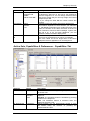
46
Description
The active extensions on the system. The length of
which is derived from the DN length configured on the
BCM
The model or component assigned against the DN.
Choose the first line that the telephone selects when a
call is made. PRI pools are not valid selections for a
Prime line.
When you assign a line pool as a prime line, the system
searches automatically for an idle line in the pool.
Assign the number of intercom buttons to a telephone.
Intercom buttons provide a telephone with access to
internal and external lines, and line pools.
NN40011-007 Issue 1.2 BCM Rls 6.0
Telephony Services
Attribute
Control Set
Values
DN – any
telephone DN
NONEDN:221 Start DN*
First display
Name
Number
Line
Auto
ID
<checkbox>
called
Description
A control Telephone can turn Scheduled Services, such
as Restriction Services on and off for the telephones
that are assigned to it. You can assign several Control
sets for the system but you can only assign one Control
Telephone per DN.
* If you change the Start DN the number reflects this
change.
Determine what call display information appears first.
This feature depends on what services you subscribe
to. Call Display information may contain the name of the
caller, the number of the caller, the name of the line in
your Business Communications Manager system that
the call is on, or all. For each telephone, you can
determine what information displays first.
Select whether you want to see the extension number
and name of the telephone you call on your display.
The Auto called ID set for target lines is the same
telephone that has appearance on that target line.
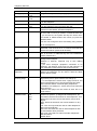
Active Sets, Capabilities & Preferences - Capabilities Tab
Attribute
DND on busy
Values
<checkbox>
Handsfree
Auto
Standard
None
HF answerback
<checkbox>
Description
Defines whether an incoming call rings if you are already
on another call.
None: The handsfree feature is not available to this
telephone.
Standard: The handsfree feature is activated by pressing
a button on the telephone.
Auto: The handsfree feature is activated when the
telephone receives a call.
Defines whether you can automatically answer a voice
call without lifting the receiver or pressing the
Handsfree/Mute button.
NN40011-007 Issue 1.2 BCM Rls 6.0
47
Telephony Services
Attribute
Pickup group
Page zone
Paging
Direct dial
Values
None
1 to 9
None
1 to 6
<checkbox>
Priority call
Set 1 to Set 5
None
<checkbox>
Auto hold
<checkbox>
Description
Assigns this telephone to a pickup group.
Assigns this telephone to a page zone.
Defines whether you can make paging announcements
from this telephone.
Defines whether you can call the Direct-dial telephone
from this telephone using the Direct-dial digit.
Defines whether this telephone can interrupt calls or
override Do Not Disturb at another telephone.
This setting determines if the system will automatically put
an active call on hold if you answer or initiate another call.
If you choose No, the system will drop the active call if
you answer or initiate another call, unless you press the
Release button.
The user can change the Auto Hold setting using Feature
Allow redirect
<checkbox>
Redirect ring
<checkbox>
Receive short
tones
<checkbox>
Silent
Monitor
Supervisor
<checkbox>
Auto Hold for
Incoming Page
<checkbox>
Intrusion
Protection level
None
Low
Med
High
48
73 on the telephone.
Defines whether the line to this telephone can be
redirected. This must be set to Y to allow call forwarding
outside the network (external call forward).
Defines whether the telephone rings briefly when a call on
one of its lines is redirected by the Line Redirection
feature (Feature 84.).
Analog equipment that is connected to the system with an
analog terminal adapter
(external or internal), responds only to tone dialling
signals.
If you have analogue equipment connected to an
extension, set Receive short tones for that extension to
Yes. Otherwise, leave Receive short tones set to No.
On two-line display telephones only, you can choose
whether the telephone can be used to allow the Silent
Monitor feature (*550).
N = if the telephone is active when a page comes in, the
page will be put on queue until the user hangs up
Y = if the telephone is active when a page comes in, the
call is automatically put on hold and the page proceeds.
Note: Business Series Terminals (BST) telephones:
• Condition: This setting is Y, active call on mute when the
page comes in.
• Results after page: the call comes off hold, but is no
longer muted.
If the break-in feature is allowed on any private network
MCDN lines (PRI SL-1) assigned to the telephone, you
must define the level of intrusion for each telephone. This
determines if the user can use the feature, and to what
degree.
None: feature is turned off, user cannot break in on any
calls
Low: user can only break into calls on other telephones
with low level protection
Med: user can break into calls on other telephones with
low and medium-level protection
High: user can break into calls on all other telephones
with this feature
Default: None
NN40011-007 Issue 1.2 BCM Rls 6.0
Telephony Services
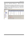
Active Sets, Capabilities &Preferences – SWCA Call Group
Tab
Generally System-wide Call Appearance (SWCA) assignments are meant to
be assigned to buttons with indicators. With this screen you can assign the
selected telephone to a SWCA assignment Call Group. You can enable or
disable Call 1 to Call 16 assignments for each set. The 16 SWCA feature
codes can be configured on the sets through administration. (Please refer to
the SWCA section of this guide)
NN40011-007 Issue 1.2 BCM Rls 6.0
49
Telephony Services
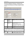
Active Sets, Capabilities & Preferences - Preferences Tab
The Preferences headings allow you to program the same settings that users
can perform at their telephones and the settings for configuring a telephone
as a hotline. The set-based options are only available to digital phones and IP
telephones.
Attribute
Language
Dialling
options
Contrast
Ring type
Values
Languages
displayed are
based on
telephone
capabilities and
system software
Standard dial
pre-dial
automatic dial
1, 2, 3,4, 5.....9
1, 2, 3, 4
Description
Choose the language for the telephone display
prompts.
Select how you want the telephone to handle
information you dial into it.
Standard: Pick up the receiver and dial.
Pre-dial: Dial the numbers, then pick up the receiver
to allow the telephone to dial the number.
Automatic dial: Use for devices like fax machines
where you want the number to dial out without
external cues.
Adjust the contrast of the display.
Select a ring pattern for the set.
Default is 1.
Warning:
If you assign a distinctive ring pattern to a telephone, and that distinctive ring pattern
has already been assigned to a line, all lines with that ring pattern will be reset to None.
If you assign a distinctive ring pattern to a line, and that distinctive ring pattern has
already been assigned to a telephone, all telephones with that ring pattern will be reset
to pattern 1.
Distinct rings
read only
This read-only field indicates the distinct ring patterns
in use
are currently in effect, if any, on any lines,
telephones, or Hunt groups on the system.
50
NN40011-007 Issue 1.2 BCM Rls 6.0
Telephony Services
Attribute
Aux. ringer
Values
<checkbox>
Business
Name
None
Business Name 1 5
Long Name
0 – 15 characters
Send Long
Name
Call log
options
<checkbox>
Available log
space
Read Only
Reset Call Log
Password
<button>
Log all calls,
No auto-logging,
No one answered
Unanswered by me
NN40011-007 Issue 1.2 BCM Rls 6.0
Description
Determine whether an auxiliary ringer (if installed)
rings for incoming calls at this telephone.
Digital Doorphone note: Before you install the
hardware, ensure this is setting is not selected in the
DN record you want to use for the doorphone.
For outgoing CLID purposes. Determine which of the
Business Names configured in Telephony, Global
Settings, Feature Settings this set will send. If set to
None, no Business Name will be sent.
Note: Only some line types/regions/network
configurations will support this feature.
For outgoing CLID purposes. The Long Name can be
sent with the Business Name (if configured) over the
network.
Note: For the Long Name to be sent, the Send Long
Name checkbox should be ticked.
Note: The maximum number of characters that can
be sent is 15. This is the total of Business Name +
Long Name.
Tick this box to send the configured Long Name with
the selected Business Name for outgoing calls.
Select how you want the telephone to handle logging
calls.
Log all calls: All calls are noted in the call log.
No auto-logging: No calls are automatically logged.
No one answered: Unanswered calls are not logged.
Unanswered by me: Unanswered calls are not
logged.
This setting indicates the total amount of space
available for call logging on the system.
This button resets the password for the call log if
users forget their password.
51
Telephony Services
Active Sets, Capabilities & Preferences, Preferences Tab –
Hotline Settings
If the telephone is to be used for Hotline purposes, i.e. picking up the receiver
automatically dials a number, configure the Hotline section.
Attribute
None
Values
Internal
Internal #
Direct dial set
DN:*
External
External #
Facility Value:
Use line nnn
Use prime line
Pool code
Use routing table
52
Description
The telephone does not automatically dial any
number.
Define the internal telephone you want to access.
Direct dial set: Will automatically dial a telephone on
the system defined as a direct dial telephone
DN: the DN of the telephone that gets automatically
dialled when the user picks up the handset
Enter the complete number for the external telephone
you want to access. Enter the line you want the call to
use. (This cannot be a target line.)
Use line nnn: Refer to line assignment for this
telephone.
Use prime line: Refer to the General record for this
telephone.
Pool code: Refer to the line pool assignment for this
telephone.
Use routing table: Refer to the routing tables. The
destination code for that table must be part of the
External #.
NN40011-007 Issue 1.2 BCM Rls 6.0
Telephony Services
Active Sets, Capabilities& Preferences – Button Programming
Table Tab
The Button Programming Table tab panels allow you to program the buttons
on a telephone with internal and external autodials and with programmed
feature keys.
You also can use these panels to remove programming from a button, making
it blank.
Note: Only the number of available buttons for the set type will be displayed
for configuration.
1. Select the button number, and click on Modify. Configure the button as
required.
Attribute
Button Number
Digits
Values
1-24 (phone
model dependant)
Internal Autodial
External Autodial
Feature
Blank
Internal Autodial #
Assigned Feature
Blank
Dialed Digits
Name
Autodial Name
Function
Value
Option
NN40011-007 Issue 1.2 BCM Rls 6.0
Description
The feature assigned against a button. Use the
Modify button to change an assigned feature.
The specific feature assigned such as a feature
code or Internal Autodial.
For External Autodials. Enter the complete dial
sequence for the external call. This will depend on
what you chose for the route in the Value field.
For External Autodials. This is the name associated
with the external number.
Useful for specifying options such as Page Zones.
53
Telephony Services
Active Sets – Button Programming Tab
By selecting a specific phone model the user can then click on a button and
be presented with a window that will allow the button to be modified with a
different feature.
54
NN40011-007 Issue 1.2 BCM Rls 6.0
Telephony Services
Active Sets, Capabilities & Preferences - User Speed Dial Tab
Speed dial numbers allow users to dial out a number with fewer button
presses than dialling out the entire dial string.
Settings
Speed Dial
Number
External Number
Value
<71-94>
Facility
Use prime line
Use routing table
<external phone
number>
Description
This is the number the user dials to dial out the
number entered in the External # field
Enter the number the telephone will
automatically dial when the user speed dial
code is entered. Remember to include the
access codes for the route you choose. i.e. 9
Select the route you want the dialled number to
take out of your system.
Note: If you choose prime line, a prime line
must be assigned to the telephone where the
code is entered.
Active Sets – Restrictions Tab
Restriction Filters should be added to schedule settings. Restriction Filters
should be configured before changing the default values, and require careful
planning and application. See the Programming Restrictions section of this
guide for further information.
NN40011-007 Issue 1.2 BCM Rls 6.0
55
Telephony Services
Setting
DN
Model
Name
Set lock
Values
Read Only
Read Only
Read Only
None
Partial
Full
Allow
last
number
Allow
saved
number
Allow link
<checkbox>
<checkbox>
<checkbox>
Description
Choose the option that sets the amount of customizing
the user can do with this telephone.
None allows access to all features.
Partial prevents:
programming autodial buttons
programming user speed dial numbers
programming feature buttons
moving line buttons
changing the display language
changing dialling modes (Automatic, Pre-, and
Standard
using Voice Call Deny
saving a number with Saved Number Redial
Full restricts all the Partial settings, plus:
changing Background Music
changing Privacy
changing Do Not Disturb
using Ring Again
using Call Forward all calls
using Send Message
using Trunk Answer
activating Services
Allows or disallows access to the Last Number Redial
feature.
Allows or disallows access to the Saved Number Redial
feature.
Allows or disallows access to the Link feature, which is
a host signalling option.
Programming Global Settings
Global Settings specify configuration that relates to the system as a whole.
The Global settings can be accessed from Configuration tab and opening
the Telephony folder followed by the Global Services tab.
56
NN40011-007 Issue 1.2 BCM Rls 6.0
Telephony Services
Feature Settings
Select the Feature Settings heading and configure the required options.
Attribute
Business
Name 1 – 5
Value
Background
music
<Checkbox>
On hold
Tones
Music
Silence
Receiver
volume
Use sys volume
Use set volume
Park mode
Lowest
Cycle
Delayed Ring
Transfer
1, 2, 3, 4, 6, 10,
or Off.
Maximum of 15
alphanumeric
characters
Description
This is the name sent via outgoing CLID over supporting
networks. Up to 5 Business Names can be entered, to
help identify the originating caller. Each extension can
select which Business Name to use, under the
Capabilities and Preferences, Preferences tab.
A Business Name can also be assigned to a Hunt Group.
Allows you to listen to music through your telephone
speaker after pressing F86 on your set. A music source
must be connected to Business Communications
Manager.
Allows you to choose what a caller hears on an external
line when the line is put on hold. Tones provide a periodic
tone. Music provides any signal from a source such as a
radio connected to Business Communications Manager.
Silence provides no audio feedback.
Allows you to specify if the volume level of a receiver or
headset returns to the system default level when a call
ends or is put on hold, or if it remains at the volume level
set at the individual telephone.
The Call park feature allows you to suspend a call. It also
allows someone to retrieve the call by entering a retrieval
code at any telephone in the system. Park mode is the
setting that determines how the system assigns a retrieval
code to parked calls.
When set to Lowest, the system chooses the lowest code
that is available when the call is parked. When set to
Cycle, the system will choose the codes in a sequence,
from lowest to highest, until all the codes have been used.
Defines whether unanswered external calls are
automatically forwarded to a prime telephone after a
certain period of time.
You must assign a prime telephone for this feature to
operate.
Assign a prime telephone to one or more external lines in
Line Data programming.
NN40011-007 Issue 1.2 BCM Rls 6.0
57
Telephony Services
Attribute
Held line
reminder
Value
Off
After 30, 60,
90, 120, 150 or
180 Seconds
Immediate
Description
Reminds you that a call at your telephone is still on hold.
You periodically hear two tones from your telephone until
you return to the call on hold.
Choose the number of seconds before the Held line
reminder feature begins at a telephone that has an
external call on hold.
Directed
pickup
<Checkbox>
Allows you to answer any calls by specifying the ringing
telephone internal number.
Directed pickup is useful when not all the telephones have
the same lines, but you want to allow co-workers to
answer a call on any external line from their telephones.
Note: Do not confuse Directed pickup with the Group
pickup feature. Group pickup, allow you to answer a call at
any telephone within a specific group without specifying
the internal number of the ringing telephone.
Page tone
Alarm set
<Checkbox>
None
DN: <number>
Defines whether a tone sounds before a page begins.
Allows you to assign a telephone on which alarm
messages appear when a problem has been detected in
the system.
Alarms are recorded in the Windows NT event log.
Set relocation
<Checkbox>
Message reply
enhancement
<Checkbox>
Ans key
Basic,
Enhanced,
Extended
Allows you to move any telephone to a new location
without losing the directory number, autodial settings,
personal speed dial codes, and any programming for that
telephone.
Activate Set relocation after you do the set installation
and programming, for more flexibility in testing equipment.
If you deactivate Set relocation while moving a set, the
internal number and programming data remain with the
physical port on Business Communications Manager.
When you connect the set somewhere else, it does not
receive the original programming.
Change this attribute to N once the set has been moved.
The Message reply enhancement feature allows you to
automatically deactivate the message-waiting indicator on
analogue telephones connected to an Analogue Station
Media Bay Module (ASM), if the reply call from the
analogue telephone to the direct-dial telephone is
answered. It does not matter where the call is answered
from by the user.
This feature also functions if the user invokes the Call
pickup feature to answer the reply call from the analogue
set. It does not however, work with the Retrieve parked
call feature.
There are up to eight answer keys that you can assign to
a set. The Answer key setting in Feature settings
window allows you to determine what types of calls alert at
the telephone.
Answer key changes do not apply to portables.
Force auto/spd
dial
over
ic/conf
58
<Checkbox>
or
This feature allows you to determine if Auto and Speed
dial codes can be transmitted during an active call. This
feature works during either a one-to-one call, or during a
conference call.
If set to N: When the user presses a key for a speed dial,
the current call will automatically be put on Hold, and the
second call will be dialed.
If set to Y: When the user presses an auto dial or speed
dial key, the system dials out the number while
NN40011-007 Issue 1.2 BCM Rls 6.0
Telephony Services
Attribute
Value
Maximum CLI
per Line
30 (read-only)
Description
maintaining the current call.
This setting indicates the maximum number of telephones
that will display CLID simultaneously for an incoming call
Timer Settings
The Timers section allows configuration of settings such as Camp Timeout,
Park Timeout, Page Timeout and Transfer Callback Timeout.
Note: The recommended setting for Transfer Callback if using Contact Center
is 4.
Note: The Transfer Call Back option can be turned off.
Attribute
Camp timeout
Park timeout
Page timeout
Transfer
callback timeout
Host delay
Values
30, 45, 60,
90,120, 150 or
180 seconds
30, 45, 60, 90,
120, 150, 180,
300 or 600
seconds
15, 30, 60, 120,
180, 300, 600
2700 seconds
Off,3, 4, 5, 6 or
12
1000,1500, 2000,
2500, 3000,
3500, 4000, 4500
milliseconds
NN40011-007 Issue 1.2 BCM Rls 6.0
Description
Allows you to assign the number of seconds before
an unanswered camped call returns to the telephone
that camped the call.
Allows you to assign the number of seconds before a
parked call on an external line returns to the
originating telephone.
Defines the period of time after which the paging
feature automatically disconnects.
Allows you to specify the number of rings before a
call-back occurs on a transferred call. You can
estimate the delay in seconds if you multiply the
number of rings by six.
Note: This setting can affect transferred calls from
voice mail (including the Contact Center) and should
be configured accordingly.
Assigns the delay between the moment an outgoing
line is selected to make an external call (for example,
by lifting the receiver off the telephone) and the
moment that Business Communications Manager
sends dialled digits or codes on the line. This ensures
that a dial tone is present before the dialling
sequence is sent. Minimizing this delay provides
faster access to the requested features.
59
Telephony Services
Advanced Feature Settings
Attribute
System
Wide
Call Appearance
Control
ONN Blocking
Tone
Values
Description
Refer to the SWCA section of this guide.
<Digits>
Pulse
<Digits>
BRI
<Digits>
Specify a code (Service Provider specified) that
allows users to block outgoing name and number
display over an analog tone trunk.
Specify a code (Service Provider specified) that
allows users to block outgoing name and number
display over an analog pulse trunk.
Specify a code (Service Provider specified) that
allows users to block outgoing name and number
display over a BRI trunk.
Refer to the Hunt Group Monitoring section of this
guide.
Click the button to reset how many log spaces each
phone has. Enter amount of space each telephone
Silent Monitor
Call Log Space
that supports logs has available (maximum 1000
for BCM50, 3000 for BCM450).
SWCA
This feature will allow calls to be parked under a programmed button and
picked up from other handsets that also have programmed SWCA buttons.
There are 16 SWCA codes that can be assigned to buttons when the
telephone is being programmed.
The codes FEATURE *521 to FEATURE *536 can be programmed onto
buttons that have a display icon to illustrate up to 16 parked calls. You also
can assign SWCA codes to a Key Interface Module (KIM).
You can also assign non-appearing SWCA assignments. This particularly
applies to the 7000 and 7100 digital phones, but can also apply to any
telephone where you do not want to have SWCA codes assigned to buttons
with indicators.
60
NN40011-007 Issue 1.2 BCM Rls 6.0
Telephony Services
FEATURE *520 searches for the next available SWCA code.
FEATURE *537 retrieves the oldest SWCA call.
FEATURE *538 retrieves the most recent SWCA call.
Note: Your telephone must have a free Intercom key to pick up SWCA calls.
Programming SWCA Controls
1. On the navigation tree, open the Telephony folder, followed by
Dialling Plan and click on General.
2. Ensure that Park prefix has a number beside it. If the Park Prefix is set
to None, SWCA keys will not work.
3. Then select Telephony, Global Settings, and Advanced Feature
settings. The SWCA Controls will be displayed.
4. Set the controls as required.
SWCA Control Settings
Field
Associate SWCA
key to call
Description
Manually - while parked:
The user either presses a free SWCA key on the telephone, or dials the feature
code for a free key. Once the call is retrieved, it is unassigned from the SWCA
key.
Manually - life of call:
The user either presses a free SWCA key on the telephone, or dials the feature
code for a free key. When the call is retrieved, it remains assigned to the SWCA
key. The key is freed only after the call is terminated.
NN40011-007 Issue 1.2 BCM Rls 6.0
61
Telephony Services
Field
Invoke SWCA
parking by Hold Y
or N
Include I/C calls
when invoking by
Hold Y or N
Description
Automatically - life of call:
When a call is answered, it will automatically be assigned to a free SWCA key,
starting with the lowest available number. When the call is retrieved, it remains
assigned to the SWCA key. The key is freed when the call is terminated.
Include I/C calls when auto associating Y or N:
Decide if you want intercom calls to automatically park on SWCA keys If you
choose Y (yes) Associate SWCA key to call must be set to Automatically - Life of
call for this feature to work.
When the user makes a call using the intercom button, the call automatically
associates with a free SWCA key, and remains assigned for the duration of the
call.
If you choose N (no) the user must manually assign an intercom call to a SWCA
key.
The call will otherwise behave by the rules of the choice made for Associate
SWCA key to call.
Choose whether calls that are put on hold will automatically assign to a SWCA
key.
Yes:
When the user presses Hold, the system attempts to re-park the call on the
current SWCA key assigned to the call, or on a free SWCA key programmed on
the telephone.
If no SWCA is currently associated with the call (Automatically - life of call is not
turned on), and there is no free SWCA key to assign to the call, the call remains
on Hold on the line it came in on. Note: In this case, the call is not available to
other telephones in the group until it can be assigned to a SWCA key or unless
they have the same line appearance as the held call.
No:
There is no interaction with SWCA keys. The call remains on Hold on the line it
came in on and is not available to other telephones in the SWCA group unless
the user manually assigns the call to a SWCA key or unless those telephones
have the same line appearance as the held call.
Choose whether intercom calls put on Hold will automatically assign to a SWCA
key.
Yes:
Invoke SWCA parking by Hold must be set to Yes to activate this feature. When
the user makes an intercom call, and puts it on Hold, the call works the same
ways as described in Invoke SWCA parking by Hold.
No:
Intercom calls will be held on the local line, regardless of what you chose in
Invoke SWCA parking by Hold.
If the intercom call was assigned to a SWCA key automatically, you can press
the SWCA key to re-park the call and make it available to other telephones in the
group. If you manually assign the intercom call to a SWCA key, the call is
automatically parked, and it becomes available to the rest of the group.
Choose one of the following configurations for the SWCA controls for your
system:
Configuration one: If you want all incoming calls to auto-associate to SWCA
assignments on the receiving telephone:
1. Associate SWCA key to call: select Automatically - life of call.
2. Include I/C calls when auto associating: select Y (yes)
3. Invoke SWCA parking by Hold: select Y (yes)
62
NN40011-007 Issue 1.2 BCM Rls 6.0
Telephony Services
4. Include I/C calls when invoking by Hold: select Y (yes)
Configuration Two: If you want incoming calls to auto-associate to SWCA
assignments on the receiving telephone, but you want calls on hold to remain
on hold at the receiving telephone, unless the user presses a SWCA button or
enters a SWCA code:
1. Associate SWCA key to call: select Automatically - life of call
2. Include I/C calls when auto-associating: select Y (yes)
3. Invoke SWCA parking by Hold: select N (no)
4. Include I/C calls when invoking by Hold: not applicable in this
configuration
Configuration three: If you want external incoming calls to auto-associate to
SWCA assignments on the receiving telephone, but you want all intercom
calls to require manual parking:
1. Associate SWCA key to call: select Automatically - life of call
2. Include I/C calls when auto associating: select N (no)
3. Invoke SWCA parking by Hold: select Y (yes)
4. Include I/C calls when invoking by Hold: select N (no)
Configuration four: If you want all calls to require the user to press a SWCA
button or enter a SWCA code:
1. Associate SWCA key to call: select either Manually - while parked or
Manually - life of call.
2. Include I/C calls when auto associating: not applicable in this
configuration.
3. Invoke SWCA parking by Hold: select N (No).
4. Include I/C calls when invoking by Hold: not applicable in this
configuration.
5. Configure the SWCA keys to indicator memory buttons on the
telephones.
Note: The SWCA support codes (FEATURE *520, FEATURE *537 and
FEATURE *538) only search for SWCA assignments that are assigned to the
telephone where the feature is invoked.
These codes are required for users who do not have buttons with indicators.
FEATURE *520 searches for the next available SWCA code.
NN40011-007 Issue 1.2 BCM Rls 6.0
63
Telephony Services
FEATURE *537 retrieves the oldest SWCA call.
FEATURE *538 retrieves the most recent SWCA call.
Programming System Speed Dials
Speed Dials allow quick and easy access to regularly dialled numbers. You
can assign destination numbers to three digit speed dial codes, which can be
activated on a handset by entering Feature 0.
BCM450 allows 999 System Speed Dials, whereas BCM50 allows 255.
1. To program System Speed Dials use the following path: Select the
Configuration tab and then the Telephony folder, Global Settings
folder, System Speed Dials.
2. For a selected Speed Dial Number (e.g. 002), enter the destination
number in the External Number field. You may need to precede the
destination number with a routing digit if using a Routing table or Prime
Line as the Facility.
64
NN40011-007 Issue 1.2 BCM Rls 6.0
Telephony Services
3. Select a Facility. This is the resource used to dial the speed dial
destination. There is the choice of Prime Line, Routing Table, Line Pool
or a specific line.
4. You can then choose to display the destination Digits, or a Name given
to the speed dial when the speed dial is activated
5. If Restrictions are used extensively on the system (see the
Programming Restrictions section of this guide), you may want to
consider bypassing general Restrictions with specific Speed Dials.
NN40011-007 Issue 1.2 BCM Rls 6.0
65
Telephony Services
Using Alpha Tagging for Name Display
The Business Communications Manager can be configured to display a caller
name for incoming lines that provide number-only CLID, such as target lines
and analog CLID lines.
When the Business Communications Manager receives incoming CLID and
the number matches a System Speed Dial Number the name associated with
the speed dial will be displayed on the Telephone sets display
You use a combination of fields within the Element Manager to set up this
feature.
Configuring the Name to Display
To determine the name to display, you add a system speed dial for the
number and enter a display name.
1. Select the Configuration tab and then the Telephony folder, Global
Settings folder, System Speed Dials
2. Then select the Speed dial to be configured (For information on setting
up General System Speed Dials refer to System Speed Dials section of
this guide)
3. Ensure that Display field is set to Name, and enter the name to be
displayed in the Name field.
66
NN40011-007 Issue 1.2 BCM Rls 6.0
Telephony Services
4. In order for the telephone to display the name, it must have the First
Display setting set to Name. This setting can be found by opening the
Telephony folder, then the Sets folder followed by Active Sets. Then
select the extension that will utilize the Alpha Tagging facility under the
Capabilities and Preferences tab. First Display should then be set to
Name selected from the drop down list.
5. The line that is assigned against the extension then needs to be
configured. Select the set that will be utilizing Alpha tagging and then
from the line access tab select the assigned line and tick the Caller ID
Set tick box.
NN40011-007 Issue 1.2 BCM Rls 6.0
67
Telephony Services
6. CLID Match Length: This determines how many digits of the dialed
number and the system speed dial must match before a name is
displayed.
Limitations:
Due to system resource limitations, only 30 telephones can have the
Caller ID Set field enabled for any given line.
If the incoming number only partially matches the CLID match length,
no name displays.
If the number matches more than one speed dial, which have different
names, the telephone displays the name of the first match.
ISDN devices do not support the alpha tagging feature.
CAP/ KIM Assignment
A CAP (Central Access Point) station acts as a central answering and
monitoring point for a group or a business. You can configure lines and quick
dial numbers that allow the person at this station to monitor and answer call
traffic into the group.
You can configure a total of 12 CAP stations on a BCM50 or 24 on a BCM450
using the CAP/KIM assignment setting. Modules that have been configured
like this will be referred to as eCAPs and eKIMs. eCaps and eKIMs can
access/monitor lines in addition to extensions.
Configuring CAP/KIM assignment
1. Ensure that the telephone you want to use for a CAP station is
configured and working.
2. Ensure that the CAP/KIM module has been installed on the appropriate
telephone.
Note: The latest version of the i2050 software phone supports a software
KEM, which can also be configured as an eKEM via this process.
68
NN40011-007 Issue 1.2 BCM Rls 6.0
Telephony Services
3. In the Element Manager, open the Telephony folder followed by
Global Settings, and select Cap Assignment.
4. The CAP # window appears.
5. Type the DN in the Set DN field for the telephones that you want to
designate as a CAP station.
6. Click on the next CAP/KIM to add another CAP station, or click
elsewhere on the navigation tree to save the setting.
NN40011-007 Issue 1.2 BCM Rls 6.0
69
Telephony Services
Hunt Groups
Configuration of Hunt Groups consists of the following steps:
1. Open the Telephony folder and select Hunt Groups. Configure the
Hunt Group operational settings.
Hunt Group Settings
Field
Name
DN
Mode
70
Values
<an alphanumeric string
naming the
Hunt Group>
<numeric>
Broadcast
Sequential
Rotary
Default:
Broadcast
Description
Provides a unique name for the Hunt Group. The default
is HGxx, where xx is the Hunt Group number 01-30.
BCM450: Enter a spare DN. BCM50: The field will already
be populated with a DN.
Choose how you want the line to present to the group.
Broadcast—simultaneously rings at each non-busy
telephone in the hunt group. All telephones receiving the
call also display the calling line identification from the line,
if the telephone or line has been configured to offer that
service.
Any of the alerted telephones can access the call.
Only one call can be presented to a hunt group at a time.
Other calls are queued until the first call is answered.
Then the next call rings on the remaining non-busy
telephones.
This feature allows the call load to be continuously spread
across the entire member group.
Sequential—rings the first telephone in the hunt group
list. If that telephone is busy, the system continues down
the hunt group priority list until a non-busy telephone
takes the call. In this case, all incoming calls are
processed simultaneously and delivered based on the
priority list.
With this feature, you can program your top salesperson
to be the first member of the Hunt group to receive
incoming calls.
Rotary—the call starts at the member telephone that
appears on the list after the telephone that answered the
last call. If that telephone is busy, the system proceeds
down the priority list until a non-busy telephone is
NN40011-007 Issue 1.2 BCM Rls 6.0
Telephony Services
Field
Values
Hunt Delay
1-10 (seconds)
If Busy
Busy tone
Queue
Overflow
Default: busy
tone
Queue
Timeout
15, 30, 45, 60,
120, 180
(seconds)
Default: 60
Overflow
<any system
DN> (including
a Hunt Group
DN)
Default: hunt
group DN
<checkbox>
Aux ringer
Distinct ring
None
Pattern 2, 3 or
4
Description
reached. As many incoming calls can be processed as
there are available telephones to accept the call, each call
being presented in the described round-robin fashion.
If Mode is either Sequential or Rotary, Hunt Delay
specifies how much time to delay offering a Queued call
to a member telephone once that telephone becomes
available.
This is to provide a break period for the users between
calls.
The default is four seconds.
Choose how you want the system to respond if all lines
appear as busy.
Busy tone: If all lines are busy, the user receives a busy
tone.
Queue: If all lines are busy, the user is put on hold for the
next available agent.
Overflow - If all members of the Hunt Group are busy on
a call from that Hunt Group, then route this call to the
Hunt
Group overflow DN. Overflow is only available if the
overflow
DN is different than the hunt group DN. Refer to the
Overflow field, below.
Choose the time in seconds for a call to remain in the
Hunt
Group.
This value defines the maximum time a call remains
queued, and the maximum time to offer a call before
sending it to overflow if it is not answered.
If the queue times out before the call connects to a
member telephone, the call is terminated.
If the call has been offered to a member telephone, but is
not answered when the queue times out, the call is
rerouted to the overflow DN.
This setting determines where unanswered calls are
routed after the Queue timeout occurs.
If a call gets overflowed back to the same Hunt Group,
the call goes to the bottom of the queue and is treated as
a new call
Defines whether an auxiliary ringer (if installed) rings for
incoming calls to a hunt group.
Select a ring pattern for the hunt group.
Default is none.
NN40011-007 Issue 1.2 BCM Rls 6.0
71
Telephony Services
2. Program the Hunt Group members (extensions). Click the Add button
under Hunt Group Members, add the member DN and click OK.
3. Set the DN Appearance Type as Ring only, Appear and Ring, or
Appear only. This affects how the Hunt Group calls alert the set. For
example, Ring only means that the DN will ring and the Intercom key
will flash, whereas Appear & Ring results in a specific button indicating
the Hunt Group call as well as the phone ringing.
72
NN40011-007 Issue 1.2 BCM Rls 6.0
Telephony Services
4. Configure lines that should be answered by the Hunt Group. Click the
Add button, add the line and click OK.
5. Configure the Business Name and Long Name settings for outgoing
CLID.
NN40011-007 Issue 1.2 BCM Rls 6.0
73
Telephony Services
Monitoring Hunt Group Calls
You can set up a number of two-line display telephones on your system to
use as supervisory telephones to monitor active hunt group calls from external
numbers.
Only telephones that have been designated as monitoring devices have
access to the FEATURE *550 code, which activates the monitoring session.
Once the session is established, a number of display key prompts allow the
supervisor to silently monitor the call, or break into the call to provide support
or instruction.
When you monitor calls you are not detected by the Hunt Group member or
caller unless Non Silent Monitoring has been enabled from within Element
Manager. Hunt Group members can be monitored by a designated set on an
active call.
Note: Hunt Group calls can only be monitored if they have originated from an
external number.
Configuring Hunt Group Monitoring
To set up Hunt Group Monitoring for your system:
1. Open the Telephony folder followed by the Global Settings folder
and select Advanced Feature Settings.
2. The Silent Monitor screen appears in the right frame.
74
NN40011-007 Issue 1.2 BCM Rls 6.0
Telephony Services
Silent Monitor Settings
Field
Monitoring mode
Values
Silent
Non silent
Description
Choose Silent if you want supervisors to be
able to break into a hunt group conversation
without giving an indication of their presence.
Choose Non silent if you want the hunt group
member and the caller to hear a conference
tone when a supervisor breaks into a hunt group
conversation.
SM sets
1 to 30
SM passwd
XXXXXX
Note: Initial monitoring is muted at the
supervisor set. If the Supervisor wants to speak
within the conversation, a display key on the
two-line display supervisor telephone is
available, once the connection is established.
Indicate the number of two-line telephones in
your system that you will allow to be used as
supervisory telephones.
(Default: 5)
A six-digit set that must be entered after the
supervisor presses FEATURE *550. To
maintain system security, change this password
frequently. (Default: 745368 (SILENT))
3. The designated sets will have to be configured so that they have
the capability to monitor a Hunt Group call.
4. Open the Telephony folder, then the Sets folder and select Active
Sets. Then select the Capabilities and Preferences tab click the
DN to have the Supervisor Monitoring facility select the capabilities
tab and tick the Silent Monitor Supervisor tick box.
Note: The monitoring extension must be a 2-line display telephone.
NN40011-007 Issue 1.2 BCM Rls 6.0
75
Telephony Services
Programming Restrictions
To set the Restrictions and Overrides to be used by the system use the
following path: Open the Telephony folder, followed by the Call Security
folder and click Restrictions Filters. Always ensure that numbers to
emergency services are not restricted.
1. Select the Restrictions from the filters list and click the Add button.
Enter the digits to be restricted and click OK.
76
NN40011-007 Issue 1.2 BCM Rls 6.0
Telephony Services
2. To add an Exception (Override) to a Restriction, select the Digits to be
restricted i.e. 07 heading and select the Override heading. Click on
Add under the Exception Digits field.
3. Enter the Exception digits and click OK.
Multiple Overrides can be added to each Restriction: however, there is a
maximum total of 400 Restrictions and Overrides allocated to the 100
programmable filters.
When setting Restrictions and Exceptions the wildcard character is ―A‖, which
represents any digit.
NN40011-007 Issue 1.2 BCM Rls 6.0
77
Telephony Services
4. Once the Restriction Filters have been created they can then be
assigned to the required DN’s open: Open the Telephony folder, then
the Sets folder and select Active Sets. Select the extension and the
Restrictions tab. set the Filter against the appropriate Schedule s
required.
Programming Scheduled Services
Scheduled Services consists of three telephony services:
Ringing Service: Allows additional telephones to ring on certain lines
when required. For example, if a receptionist is unavailable to take
calls during lunchtime, the lines that normally ring on that extension
can be programmed to ring at other extensions.
Restriction Service: Alternate restrictions can be set for different
periods of the day. For example, at night time it is possible to restrict
calls from an extension to international numbers, whereas during the
day this facility is allowed.
Routing Service: Alternate routes can be programmed for different
times of the day.
Services can be activated either manually by the use of Feature codes
(F871=Ringing, F872=Restriction, F873=Routing), or automatically by
programming the respective Service setting to Auto.
78
NN40011-007 Issue 1.2 BCM Rls 6.0
Telephony Services
Ringing Service
The programming of a Ringing Service consists of configuring a Ring Group
(essentially a list of extensions required to ring) and assigning the group to a
line. Again, the service can be activated by use of a Feature code (Manual
setting), or programmed to activate at certain times of the day. (Auto setting).
1. To assign extensions to a Ring Group, open the Telephony folder and
click Ring Groups. Click the Ring Group to be configured. Under the
Members field click on Add to add an extension (DN) to the group.
Click OK when you’ve entered the extension.
Note: It is recommended that you do not use Ring Group 001, unless you
want this Ring Group to be applied to all lines. Ring Group 001 is applied to all
lines by default.
NN40011-007 Issue 1.2 BCM Rls 6.0
79
Telephony Services
2. To assign the Ring Group to a line, click the Line Settings tab followed
by the line to be used schedule to be used.
3. The under the Line Settings Field enter the Ring Group to be used
against the appropriate schedule.
4. To configure if the service is to be activated manually or automatically,
open the Telephony folder and click Scheduled Services. Select the
required schedule. Click the Ringing Service drop down box and the
appropriate service setting.
80
NN40011-007 Issue 1.2 BCM Rls 6.0
Telephony Services
Note: If using the Auto setting, you must set the times for that schedule
appropriately. Refer to the Scheduled Services – Times, Names, and
Service Control Passwords section of this guide for more information.
Ringing Service Settings
Attribute
Service setting
Value
Off
Manual
Auto
Trunk answer
< Checkbox >
Extra dial set
None
DN XX
DN
<control
set>
Description
Manual allows you to turn the service on and off at any
time from a control set using the Ringing service feature
code (F871).
Auto allows you to program a stop and start time for a
service. You are still able to start and stop the service by
entering the appropriate Services feature code at a
control set. If you select this setting, you will have to set
start and stop times.
Off prevents the service from being activated.
Trunk answer allows you to answer, from any telephone,
an external call that is ringing at another telephone in your
office if the Ringing Service is active on that line at the
time of the call. If the service is not active, you cannot
answer the call.
This is useful if the other telephones are not assigned the
same lines as the telephone you are using to answer the
call.
The Extra dial set attribute allows you to assign an
additional direct-dial set for each schedule.
Note: The extra dial set is activated during a schedule by
entering the Ringing service feature code from a directdial set. This does not activate the Ringing service unless
the direct-dial set is also a control set.
Restriction Service
To utilise alternate restriction scheduled services, ensure that the required
Restriction Filters have been programmed. You must then ensure that the
correct Restriction Filters are assigned to the required DN’s (extensions).
NN40011-007 Issue 1.2 BCM Rls 6.0
81
Telephony Services
1. Define whether each Restriction Schedule should be activated
Manually, Automatically, or not at all.
Note: If using the Auto setting, you must set the times for that schedule
appropriately. Refer to the Scheduled Services – Times, Names, and
Service Control Passwords section of this guide for more information.
Restriction Service Settings
Attribute
Service setting
Value
Off
Auto
Manual
Description
Manual allows you to turn the service on and off at any
time from a control set using the Restriction service
feature code (F872).
Auto allows you to program a stop and start time for a
service. You are still able to start and stop the service
by entering the appropriate Services feature code at a
control set. If you select this setting, you will have to set
start and stop times.
Off prevents the service from being activated.
Routing Service
To utilise alternate routing scheduled services, ensure that the required
Routes and Destination codes have been programmed.
1. Define whether each Routing Schedule should be activated Manually,
Automatically, or not at all.
Note: If using the Auto setting, you must set the times for that schedule
appropriately. Refer to the Scheduled Services – Times, Names, and
Service Control Passwords section of this guide for more information.
82
NN40011-007 Issue 1.2 BCM Rls 6.0
Telephony Services
Routing Service Settings
Attribute
Service setting
Value
Off
Auto
Manual
Overflow
routing
<checkbox>
Description
Manual allows you to turn the service on and off at any time
from a control set using the Routing service feature code
(F873).
Auto allows you to program a stop and start time for a
service. You are still able to start and stop the service by
entering the appropriate Services feature code at a control
set. If you select this setting, you will have to set start and
stop times. See the section on schedule times for
information on programming times.
Off prevents the service from being activated.
If all the lines used by a route are busy when a call is made,
you can program Routing service to overflow to the route
used for normal mode. If this happens, the set sounds a
warning tone and displays the message Expensive route.
The caller can then release the call to avoid using the
normal route, or continue with the call.
Tips: A schedule must be active for overflow routing to be
in effect. Overflow routing is not available in normal mode.
You must create an overflow route to be used with each
destination code. In this way, every route used with a
scheduled mode that has overflow service must have an
alternate route in normal service.
Scheduled Services - Times, Names and Service Control
Passwords
1. When manually activated, some scheduled services may require a
password. This is the password entered in the Service Control
Password field.
NN40011-007 Issue 1.2 BCM Rls 6.0
83
Telephony Services
2. To name a schedule, double click on the schedule to be named.
Schedule 0 is always ―normal‖ and cannot be renamed.
3. Set the schedule times accordingly for each day.
Note: Schedule times do not flow over midnight, i.e. setting a start time of
23:00 and stop time of 07:00 means that the schedule will start at midnight,
stop at 07:00, then re-start at 23:00 and stop at midnight.
84
NN40011-007 Issue 1.2 BCM Rls 6.0
Telephony Services
Additional Configuration
The following configuration sections may not be required in all situations.
Voice Message Centres
Voice Message Centres are remote Voicemail service providers. Thus,
Voicemail mailboxes and messages can be stored on a system external to the
BCM.
1. To program Voice Message Centres (Voicemail services via external
provider) use the following path: open the Applications folder, and
select Voice Messaging/Contact Center.
If using Voicemail on a Meridian system the path can be defined here.
Voice Message Center Settings
Field
External #
Values
<phone number>
Message wait
Indicate String
<string>
Message wait
Cancellation
string
<string>
NN40011-007 Issue 1.2 BCM Rls 6.0
Description
This is the number of the remote voice message
system.
Indicates that the message centre has a message in the
mailbox. This is a default NSI string for message
waiting.
Indicates that the voice messages have been retrieved.
This is a default NSI string for message waiting.
85
Telephony Services
Hospitality
In a temporary room occupancy setting, such as hotels or hospitals, guests
and staff gain improved services through immediate access to basic functions
like:
Wake-up services or reminders via alarms on the room telephones
Accurate tracking of the room service requirements, such as cleaning
schedules and occupancy.
The system classifies telephones as one of three types of telephones:
Common set: This type of telephone can be found in a lobby, office, or
common area. It is not associated with a room and does not have
access to all of the hospitality features. These telephones are Business
Communications Manager telephones or analogue telephones
connected to an analogue terminal adapter (ATA 2).
Room set: This type of telephone is assigned to a room. You can
assign up to five telephones to the same room (they all share the same
room number). These telephones can be any Business
Communications Manager telephone or an analogue telephone
connected to an ATA 2.
Hospitality Services (HS) admin set: This type of telephone is any
two-line display Business Communications Manager telephone. You
can program a hospitality services telephone to require the entry of an
Administrative desk password before the system grants access to
hospitality administrative-level service control.
1. To program Hospitality features use the following path: Telephony >
Hospitality.
86
NN40011-007 Issue 1.2 BCM Rls 6.0
Telephony Services
Field
Services
change time
Values
<24 hour digital
time>
Desk
password
<up to six digits>
Room
condition
password No.
<up to six digits>
Description
Identify when the occupied rooms will change from
service done to service required.
Format: HHMM, i.e. 1400 = 2 p.m.
HH = 0 to 23; MM = 0 to 59
Enter the password that will be required to access all
the Hospitality administrative features.
Security: We strongly recommend that you change the
default password, and frequently change the desk
password to prevent unauthorized entry.
Default password: 4677 (HOSP)
Set the password that will allow access to the Room
condition feature (F876).
Default password: 4677 (HOSP)
Call Restrictions
Field
Vacant filter
Values
<two-digit code>
Basic filter
<two-digit code>
Mid filter
<two-digit code>
Full filter
<two-digit code>
NN40011-007 Issue 1.2 BCM Rls 6.0
Description
Enter a code that indicates which calls are allowed
when a room is empty, (i.e. 911).
Enter a code that indicates which calls are allowed for a
basic room phone, (i.e. 911, and internal calls only).
Enter a code that indicates which calls are allowed for a
phone with mid service. (i.e. 911, internal calls, and 1800 numbers only)
Enter a code that indicates which calls are allowed for a
phone with full service. (i.e. no restrictions).
87
Telephony Services
Wake Up Call Settings
Field
Attempts
Values
1, 2, 3, 4, 5
Retry interval
(in minutes)
2, 4, 6, 8,
(in seconds)
10, 15, 20, 25,
30, 35, 40, 45, 50
Alarm duration
Description
Select the number of times the Alarm time feature
attempts to alert the occupant before cancelling.
Select the interval between each attempt to send the
alarm.
Select the period that a telephone alerts for each
alarm attempt.
Expired Wake-Up Call Settings
88
NN40011-007 Issue 1.2 BCM Rls 6.0
Telephony Services
Field
Notify DN
Values
None/DN: <telephone DN>
Use tone
<check box>
Description
Enter a telephone DN if you want to
notify a specific telephone when an
alarm expires.
Choose whether you want the user to
hear a tone when the alarm expires.
Rooms Tab
The Hospitality - Rooms panel tab allows you to assign telephones to a room.
You can assign a maximum of five telephone DN's to a room.
Field
DN
Values
<Read-only>
Name
Max 7 Characters
Model
Select from
Dropdown List
This is the model name from the
DN record.
Room number
<any digit from 1
to 32767>
Checkbox
Enter the room that contains the telephone with this DN.
Requires desk
password
NN40011-007 Issue 1.2 BCM Rls 6.0
Description
This is the DN of a telephone assigned to a room.
If set to yes, the telephone requires a password to
access administrative-level hospitality features (features
877-879).
If set to no, the telephone does not require any
passwords to access the features.
Desk passwords are created using the main Hospitality
command.
89
Telephony Services
Renumbering DN’s & Target Line Information
There are two programming elements that can be sequentially renumbered
within Element Manager:
DN’s
Target Lines
The DN Renumbering feature allows the following items to be changed:
DN’s: A single or range of DN’s can be renumbered to other more
convenient values. For example, if there was a need to change DN
numbers 221-230 to 621-630 then the Renumber feature would allow
this.
OLI’s: Public and Private OLI’s can be easily assigned or changed
across a range of DN’s.
The Target Line Renumbering feature allows the following items to be
changed:
Target Line Assignment: Target Lines can be sequentially assigned to
designated DN’s. This process is useful if the received numbers have
already been assigned to the Target Lines.
Received Numbers: Public and Private received numbers can be
assigned sequentially to Target Lines. This is a convenient method of
performing this process.
Renumbering DN’s and OLI’s
Renumbering DN’s
Use the following procedure to change a single or range of DNs numbers to
more convenient numbers. It is also possible to move existing mailboxes
using this process.
The attributes of the original DN such as name, call forward settings, line
assignments etc., will be moved to the new DN(s).
1. Launch Element Manager and connect to the BCM.
90
NN40011-007 Issue 1.2 BCM Rls 6.0
Telephony Services
2. In the Configuration tab, open the Telephony folder, followed by
Sets, and click on Active Sets. (The following process could be
performed in Active Application DNs, Inactive DNs, and All DNs.)
3. Click on the Renumber… button.
4. The Set Renumber dialog box appears. Select DN from the Attribute
drop down list.
5. Enter the range of DN’s to be renumbered in the Begin DN number
and End DN number fields. Enter the DN number that you want to
start renumbering to in the New begin value field.
NN40011-007 Issue 1.2 BCM Rls 6.0
91
Telephony Services
6. If you want to move mailboxes associated with the original DN’s to the
new DN’s, check the Move Voice Mail boxes check box. Click OK to
renumber the DN’s.
7. If selecting the Move Voice Mail boxes option, voice mail data will be
lost. Click OK to continue
8. Click OK to continue.
9. The new DN numbers will be displayed. Note that the port numbers
remain the same.
Renumbering OLI’s
The Renumber feature allows quick and easy numbering of Public and Private
OLI’s, if they weren’t already correctly set in during Telephony Resources
configuration.
OLI’s, or the Outgoing Line Identifier, is used to display the configured OLI
number of the dialing BCM extension at the receiving end. Separate OLI’s can
be specified for dialing over public or private networks.
The procedure allows selection of DN’s to apply the OLI’s to, and the start OLI
number to sequentially assign OLI’s from.
Use the following procedure to apply OLI’s to a range of DN’s.
1. Launch Element Manager and connect to the BCM.
92
NN40011-007 Issue 1.2 BCM Rls 6.0
Telephony Services
2. In the Configuration tab, open the Telephony folder, followed by
Sets, and click on Active Sets. (The following process could be
performed in Active Application DNs, Inactive DNs, and All DNs.)
3. Click on the Renumber… button.
4. The Set Renumber dialog box appears. Select either Public OLI or
Private OLI from the Attribute drop down list, depending on whether
OLI’s are being configured for the public or private network.
5. Enter the range of DN’s to apply the OLI’s to in the Begin DN number
and End DN number fields. Enter the start of the OLI range in the New
begin value field. OLI’s will be applied sequentially from this value to
the specified range of DN’s.
6. Click OK to apply the OLI’s.
NN40011-007 Issue 1.2 BCM Rls 6.0
93
Telephony Services
7. The updated OLI’s will appear in the selected OLI field.
Renumbering Target Line Assignments & Received Numbers
Renumbering Target Line Assignments
The Renumber feature can be used to assign a range of Target Lines to a
range of DN’s, specified by the DN begin value. Each Target Line will be
mapped sequentially from the specified DN upwards.
Use the following procedure to assign Target Lines to DN’s.
Note: Existing Target Lines will not be replaced by the newly assign Target
Lines on the DN’s specified in this process.
1. Launch Element Manager and connect to the BCM.
94
NN40011-007 Issue 1.2 BCM Rls 6.0
Telephony Services
2. In the Configuration tab, open the Telephony folder, followed by
Lines, and click on Target Lines. (The following process could be
performed in Active Physical Lines, Active VoIP Lines, Inactive Lines,
and All Lines, but as this process only relates to Target Lines it is
recommended to perform this from the Target Lines section.)
3. Click on the Renumber button.
4. The Line Renumber dialog box appears. Select Assign Target Lines
from the Attribute drop down list.
5. Enter the range of Target Lines to be assigned in the Begin line
number and End line number fields, and the first DN to have the
target lines sequentially assigned in the DN begin value fields.
6. Click OK to assign the Target Lines.
NN40011-007 Issue 1.2 BCM Rls 6.0
95
Telephony Services
7. Select the Target Line and click on the Assigned DNs tab in the lower
pane to view the Target Line assignments (per line basis).
Renumbering Received Numbers
The Renumber feature provides a quick and convenient method of assigning
ranges of public and private received numbers to Target Lines.
Use the following procedure to assign received numbers to Target Lines using
the Renumber feature.
1. Launch Element Manager and connect to the BCM.
2. In the Configuration tab, open the Telephony folder, followed by
Lines, and click on Target Lines. (The following process could be
performed in Active Physical Lines, Active VoIP Lines, Inactive Lines,
and All Lines, but as this process only relates to Target Lines it is
recommended to perform this from the Target Lines section.)
3. Click on the Renumber button.
96
NN40011-007 Issue 1.2 BCM Rls 6.0
Telephony Services
4. The Line Renumber dialog box appears. Select either Public receive
number or Private receive number from the Attribute drop down list,
depending on whether received numbers are being configured for the
public or private network.
5. Enter the range of Target Lines to be configured in the Begin line
number and End line number fields, and the first received number to
sequentially assign from in the New begin value field.
6. Click OK to assign the received numbers.
7. The assigned received numbers will be displayed.
NN40011-007 Issue 1.2 BCM Rls 6.0
97
Telephony Services
Avaya Documentation Links
98
Configuration – System
Configuration – Devices
Configuration – Telephony
NN40011-007 Issue 1.2 BCM Rls 6.0