1
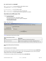
Ethernet Switch 470/460/BPS
Software Release 3.1.8
1. Release Summary
Release Date: 14-Dec-2005
Purpose:
Software patch release to address customer found software issues.
2. Important Notes Before Upgrading to This Release
With 3.1.8 software release, the Interoperability Software Version Numbers (ISVN) is changed to 3.
When working with a mixed stack, all the ISVNs should be identical.
If the ISVNs are different, the units will not stack up.
3. Platforms Supported
Ethernet Switch 460/470
BPS 2000
4. Notes for Upgrade
Please see “Release Notes for BayStack Operating System Switching Software (BoSS 3.1) for BayStack 460,
470, and BPS 2000” (Part No. 215148-D, available at http://www.nortel.com/support. Under Switches & Hubs,
select Ethernet Switches, then select Ethernet Switch 470-24T from the list of products.) for details on how to
upgrade your Policy Switch.
File Names For This Release
File Name
Module or File Type
File Size (bytes)
470_31812.img
Agent code image
1,942,642
470_31813s.img
Agent code image (SSH)
1,890,345
5. Version of Previous Release
Software Version 3.1.7
6. Compatibility
The software version 3.1.8 is compatible with BayStack 450 software version 4.5.4.
This software release is managed with the Java Device Manager (JDM) release 5.9.5.
The stack monitor feature will be supported in 5.9.6 release of JDM.
©2005 Nortel Networks Limited
Rev: 1.1 (14-Dec-2005)
Page 1 of 5
7. Changes in This Release
New Features in This Release
Stack Monitor
The Stack Monitor feature provides the ability to monitor the health of a stack by monitoring the number of active
units in the stack. With stacked switches, MLT links are often connected to separate units in a distributed MLT
(DMLT). In the event that the connections between switches in the stack fail, a situation can arise where the
DMLT links are no longer connected to a single stack, but to a combination of units that are no longer connected
to each other. From the other end of the DMLT, the trunk links appear to be functioning properly. However, as
traffic is no longer flowing between the units, connectivity problems could occur.
To address this issue, Release 3.1.8 software supports the Stack Monitor feature. When a stack is broken, this
feature allows the remaining portion of the stack and any units that have been disconnected from the stack to
send SNMP traps. If the stack or the disconnected units are still connected to the network, they generate event
logs and send trap messages to the management station to notify the administrator of the event. Once the
problem is detected, the stack and disconnected units continue to generate log events and send traps at a userconfigurable interval until the situation is remedied (or the feature is disabled).
No actions are taken to change the current operation of the standalone units or the stack.
MIB support for this feature will be released at a later date.
Control Parameters
You can configure the Stack Monitor by setting the following parameters:
• Stack Monitor enable and disable (default: disabled)
• stack size (range: 2 to 8 units; default: 2)
• trap and event logging interval (range: 30 to 300 seconds; default: 60)
The Stack Monitor settings are saved to NVRAM and distributed to all units within a stack.
When the Stack Monitor is enabled, the feature determines the number of units currently in the stack and
automatically sets the correct value for the stack size parameter.
Once the feature is enabled, any change to the number of units in the stack triggers the sending of traps.
To ensure that disconnected switches can send traps, Nortel recommends that you set a switch IP on any units
that have MLT links. This ensures that the units have the IP capability to send traps if they become standalone
units. While this requires additional IP addresses, it provides the most robust operation.
Configuring Stack Monitor
You can use the CLI to configure the Stack Monitor feature. For details, refer to the following:
• “show stack-monitor command”
• “stack-monitor command”
• “default stack-monitor command”
• “no stack-monitor command”
For details on configuring the Stack Monitor feature using JDM, refer to the following:
• “Stack Monitor tab”
©2005 Nortel Networks Limited
Rev: 1.1 (14-Dec-2005)
Page 2 of 5
Show stack-monitor command
The show stack-monitor command displays the status of the Stack Monitor feature.
The syntax for the show stack-monitor command is:
show stack-monitor
The show stack-monitor command is in the privExec command mode.
A sample output of the show stack-monitor command:
470-24T#show stack-monitor
Status: disabled
Stack size: 2
Trap interval: 60
Stack-monitor command
The stack-monitor command enables the Stack Monitor feature.
The syntax for the stack-monitor command is:
stack-monitor [enable] [stack-size <2-8>]
[trap-interval <30-300>]
The stack-monitor command is in the config command mode.
Table 1 describes the parameters and variables for the stack-monitor command.
Table 1 stack-monitor command parameters and variables
Parameters and variables
Description
enable
Enables Stack Monitoring.
stack-size <2-8>
Sets the size of the stack to be monitored. Valid range is 2 to 8.
trap-interval <30-300>
Sets the interval between traps, in seconds. Valid range is 30 to 300.
Default stack-monitor command
The default stack-monitor command sets the Stack Monitor parameters to their default values.
The syntax for the default stack-monitor command is:
default stack-monitor [enable] [stack-size]
[trap-interval]
The default stack-monitor command is in the config command mode.
Table 2 describes the parameters and variables for the default stack-monitor command.
Table 2 default stack-monitor command parameters and variables
Parameters and variables Description
enable
Sets the Stack Monitor feature to disabled (the default state for the feature).
stack-size
Sets the size of the stack to be monitored to the default value: 2.
trap-interval
Sets the interval between traps to the default value: 60 seconds.
Note: If you do not specify a parameter for this command, all Stack Monitor parameters are set to their default values.
©2005 Nortel Networks Limited
Rev: 1.1 (14-Dec-2005)
Page 3 of 5
No stack-monitor command
The no stack-monitor command disables the Stack Monitor feature.
The syntax for the no stack-monitor command is:
No stack-monitor or no stack-monitor enable
The no stack-monitor command is in the config command mode.
The no stack-monitor command does not have any parameters or variables.
Stack Monitor tab (JDM version 5.9.5)
To open the Stack Monitor tab:
1 Select the chassis.
2 From the shortcut menu, choose Edit > Chassis.
The Chassis dialog box opens with the System tab displayed.
3 Click the Stack Monitor tab.
The Stack Monitor tab opens.
Figure 1 Stack Monitor tab
Table 3 describes the Stack Monitor tab fields.
Table 3 Stack Monitor tab fields
Field
Description
StackErrorNotificationEnabled
Enables or disables the Stack Monitoring feature.
ExpectedStackSize
Sets the size of the stack to be monitored. Valid range is 2 to 8.
StackErrorNotificationInterval Sets the interval between traps, in seconds. Valid range is 30 to 300.
Old Features Removed From This Release
None.
Problems Resolved in This Release
Ina stack of 2 units, the counters for GIG ports used 32-bit counters for the IfHCInOctets objects (Q00827524).
When downloading the configuration file of a stack of 470’s, the downloaded file over the TFTP server had a
slightly different size than the original. (Q01000623-02).
In a 470 stack, the non-base units did not use 64-bit counters (Q01148220-02).
©2005 Nortel Networks Limited
Rev: 1.1 (14-Dec-2005)
Page 4 of 5
When a BPS or a 460/470 is connected to a multicast router/querier via MLT or SMLT, if the first link in the MLT
failed the IGMP reports sent in response to a query were never forwarded out of the second MLT link.
(Q01130212).
Whenever a specific Mac-Address [08-00-09-A0-75-40] was searched from a VLAN other than its own, it resulted
in stack instability (Q01197202-01).
When a user logged off using Windows OS and the checked the box: "Authenticate as computer when computer
information is available", the 470 did not send the computer name to OSM but instead sent the previous logged
peer username. (Q01101634-02).
Mac security could not be enabled on the ports of a non-base unit (Q01152518).
Using EAPOL radius for authentication with a Primary and a Secondary Radius server, nearly half of the client
authentication requests went to the secondary server while the primary one was active (Q01180650-02).
There was a mismatch in the syntax of ASCII config output and CLI commands. (Q01224947).
If the switch had a trap receivers (SNMP-server host) configured in the local management subnet and one or
more of those trap receivers were not ARPable, and events were generated that triggered messages to be added
to the log file and sent out as traps and the switch was also performing other system activity (such as responding
to SNMP queries or updating the CAMs in stacked configurations), then the switch memory gradually got
fragmented. (Q01096914).
EAPoL Port Status changed from Auto to forceUnAuthorize mode (Q01226570).
JDS Uniphase GBIC came up as “Unsupported”, but it properly passed traffic (Q01260800-05).
8. Outstanding Issues
None.
9. Known Limitations
If during the download of the image, a stack receives an EAPOL authentication request, then the stack falls apart
(Q00932428).
Console on a non-base unit might freeze after resetting base unit from the non-base unit and “show stackmonitor” command (Q01266026).
10. Documentation Corrections
For other known issues, please refer to the product release notes and technical documentation available from the
Nortel Technical Support web site at: http://www.nortel.com/support .
Copyright ©2005 Nortel Networks Limited - All Rights Reserved. Nortel, Nortel Networks, the Nortel logo, Globemark, and <product family>
are trademarks of Nortel Networks Limited.
The information in this document is subject to change without notice. The statements, configurations, technical data, and recommendations in
this document are believed to be accurate and reliable, but are presented without express or implied warranty. Users must take full
responsibility for their applications of any products specified in this document. The information in this document is proprietary to Nortel.
To access more technical documentation, search our knowledge base, or open a service request online, please visit Nortel Technical Support
on the web at: http://www.nortel.com/support
©2005 Nortel Networks Limited
Rev: 1.1 (14-Dec-2005)
Page 5 of 5