1
BayRS Version 14.00
Part No. 308647-14.00 Rev 00
September 1999
4401 Great America Parkway
Santa Clara, CA 95054
Configuring VRRP Services
Copyright © 1999 Nortel Networks
All rights reserved. Printed in the USA. September 1999.
The information in this document is subject to change without notice. The statements, configurations, technical data,
and recommendations in this document are believed to be accurate and reliable, but are presented without express or
implied warranty. Users must take full responsibility for their applications of any products specified in this document.
The information in this document is proprietary to Nortel Networks NA Inc.
The software described in this document is furnished under a license agreement and may only be used in accordance
with the terms of that license. A summary of the Software License is included in this document.
Trademarks
NORTEL NETWORKS is a trademark of Nortel Networks.
ANH, ASN, BayRS, BayStack, and BCC are trademarks of Nortel Networks.
All other trademarks and registered trademarks are the property of their respective owners.
Restricted Rights Legend
Use, duplication, or disclosure by the United States Government is subject to restrictions as set forth in subparagraph
(c)(1)(ii) of the Rights in Technical Data and Computer Software clause at DFARS 252.227-7013.
Notwithstanding any other license agreement that may pertain to, or accompany the delivery of, this computer
software, the rights of the United States Government regarding its use, reproduction, and disclosure are as set forth in
the Commercial Computer Software-Restricted Rights clause at FAR 52.227-19.
Statement of Conditions
In the interest of improving internal design, operational function, and/or reliability, Nortel Networks NA Inc. reserves
the right to make changes to the products described in this document without notice.
Nortel Networks NA Inc. does not assume any liability that may occur due to the use or application of the product(s)
or circuit layout(s) described herein.
Portions of the code in this software product may be Copyright © 1988, Regents of the University of California. All
rights reserved. Redistribution and use in source and binary forms of such portions are permitted, provided that the
above copyright notice and this paragraph are duplicated in all such forms and that any documentation, advertising
materials, and other materials related to such distribution and use acknowledge that such portions of the software were
developed by the University of California, Berkeley. The name of the University may not be used to endorse or
promote products derived from such portions of the software without specific prior written permission.
SUCH PORTIONS OF THE SOFTWARE ARE PROVIDED “AS IS” AND WITHOUT ANY EXPRESS OR
IMPLIED WARRANTIES, INCLUDING, WITHOUT LIMITATION, THE IMPLIED WARRANTIES OF
MERCHANTABILITY AND FITNESS FOR A PARTICULAR PURPOSE.
In addition, the program and information contained herein are licensed only pursuant to a license agreement that
contains restrictions on use and disclosure (that may incorporate by reference certain limitations and notices imposed
by third parties).
ii
308647-14.00 Rev 00
Nortel Networks NA Inc. Software License Agreement
NOTICE: Please carefully read this license agreement before copying or using the accompanying software or
installing the hardware unit with pre-enabled software (each of which is referred to as “Software” in this Agreement).
BY COPYING OR USING THE SOFTWARE, YOU ACCEPT ALL OF THE TERMS AND CONDITIONS OF
THIS LICENSE AGREEMENT. THE TERMS EXPRESSED IN THIS AGREEMENT ARE THE ONLY TERMS
UNDER WHICH NORTEL NETWORKS WILL PERMIT YOU TO USE THE SOFTWARE. If you do not accept
these terms and conditions, return the product, unused and in the original shipping container, within 30 days of
purchase to obtain a credit for the full purchase price.
1. License Grant. Nortel Networks NA Inc. (“Nortel Networks”) grants the end user of the Software (“Licensee”) a
personal, nonexclusive, nontransferable license: a) to use the Software either on a single computer or, if applicable, on
a single authorized device identified by host ID, for which it was originally acquired; b) to copy the Software solely
for backup purposes in support of authorized use of the Software; and c) to use and copy the associated user manual
solely in support of authorized use of the Software by Licensee. This license applies to the Software only and does not
extend to Nortel Networks Agent software or other Nortel Networks software products. Nortel Networks Agent
software or other Nortel Networks software products are licensed for use under the terms of the applicable Nortel
Networks NA Inc. Software License Agreement that accompanies such software and upon payment by the end user of
the applicable license fees for such software.
2. Restrictions on use; reservation of rights. The Software and user manuals are protected under copyright laws.
Nortel Networks and/or its licensors retain all title and ownership in both the Software and user manuals, including
any revisions made by Nortel Networks or its licensors. The copyright notice must be reproduced and included with
any copy of any portion of the Software or user manuals. Licensee may not modify, translate, decompile, disassemble,
use for any competitive analysis, reverse engineer, distribute, or create derivative works from the Software or user
manuals or any copy, in whole or in part. Except as expressly provided in this Agreement, Licensee may not copy or
transfer the Software or user manuals, in whole or in part. The Software and user manuals embody Nortel Networks’
and its licensors’ confidential and proprietary intellectual property. Licensee shall not sublicense, assign, or otherwise
disclose to any third party the Software, or any information about the operation, design, performance, or
implementation of the Software and user manuals that is confidential to Nortel Networks and its licensors; however,
Licensee may grant permission to its consultants, subcontractors, and agents to use the Software at Licensee’s facility,
provided they have agreed to use the Software only in accordance with the terms of this license.
3. Limited warranty. Nortel Networks warrants each item of Software, as delivered by Nortel Networks and properly
installed and operated on Nortel Networks hardware or other equipment it is originally licensed for, to function
substantially as described in its accompanying user manual during its warranty period, which begins on the date
Software is first shipped to Licensee. If any item of Software fails to so function during its warranty period, as the sole
remedy Nortel Networks will at its discretion provide a suitable fix, patch, or workaround for the problem that may be
included in a future Software release. Nortel Networks further warrants to Licensee that the media on which the
Software is provided will be free from defects in materials and workmanship under normal use for a period of 90 days
from the date Software is first shipped to Licensee. Nortel Networks will replace defective media at no charge if it is
returned to Nortel Networks during the warranty period along with proof of the date of shipment. This warranty does
not apply if the media has been damaged as a result of accident, misuse, or abuse. The Licensee assumes all
responsibility for selection of the Software to achieve Licensee’s intended results and for the installation, use, and
results obtained from the Software. Nortel Networks does not warrant a) that the functions contained in the software
will meet the Licensee’s requirements, b) that the Software will operate in the hardware or software combinations that
the Licensee may select, c) that the operation of the Software will be uninterrupted or error free, or d) that all defects
in the operation of the Software will be corrected. Nortel Networks is not obligated to remedy any Software defect that
cannot be reproduced with the latest Software release. These warranties do not apply to the Software if it has been (i)
altered, except by Nortel Networks or in accordance with its instructions; (ii) used in conjunction with another
vendor’s product, resulting in the defect; or (iii) damaged by improper environment, abuse, misuse, accident, or
negligence. THE FOREGOING WARRANTIES AND LIMITATIONS ARE EXCLUSIVE REMEDIES AND ARE
IN LIEU OF ALL OTHER WARRANTIES EXPRESS OR IMPLIED, INCLUDING WITHOUT LIMITATION ANY
WARRANTY OF MERCHANTABILITY OR FITNESS FOR A PARTICULAR PURPOSE. Licensee is responsible
308647-14.00 Rev 00
iii
for the security of its own data and information and for maintaining adequate procedures apart from the Software to
reconstruct lost or altered files, data, or programs.
4. Limitation of liability. IN NO EVENT WILL NORTEL NETWORKS OR ITS LICENSORS BE LIABLE FOR
ANY COST OF SUBSTITUTE PROCUREMENT; SPECIAL, INDIRECT, INCIDENTAL, OR CONSEQUENTIAL
DAMAGES; OR ANY DAMAGES RESULTING FROM INACCURATE OR LOST DATA OR LOSS OF USE OR
PROFITS ARISING OUT OF OR IN CONNECTION WITH THE PERFORMANCE OF THE SOFTWARE, EVEN
IF NORTEL NETWORKS HAS BEEN ADVISED OF THE POSSIBILITY OF SUCH DAMAGES. IN NO EVENT
SHALL THE LIABILITY OF NORTEL NETWORKS RELATING TO THE SOFTWARE OR THIS AGREEMENT
EXCEED THE PRICE PAID TO NORTEL NETWORKS FOR THE SOFTWARE LICENSE.
5. Government Licensees. This provision applies to all Software and documentation acquired directly or indirectly by
or on behalf of the United States Government. The Software and documentation are commercial products, licensed on
the open market at market prices, and were developed entirely at private expense and without the use of any U.S.
Government funds. The license to the U.S. Government is granted only with restricted rights, and use, duplication, or
disclosure by the U.S. Government is subject to the restrictions set forth in subparagraph (c)(1) of the Commercial
Computer Software––Restricted Rights clause of FAR 52.227-19 and the limitations set out in this license for civilian
agencies, and subparagraph (c)(1)(ii) of the Rights in Technical Data and Computer Software clause of DFARS
252.227-7013, for agencies of the Department of Defense or their successors, whichever is applicable.
6. Use of Software in the European Community. This provision applies to all Software acquired for use within the
European Community. If Licensee uses the Software within a country in the European Community, the Software
Directive enacted by the Council of European Communities Directive dated 14 May, 1991, will apply to the
examination of the Software to facilitate interoperability. Licensee agrees to notify Nortel Networks of any such
intended examination of the Software and may procure support and assistance from Nortel Networks.
7. Term and termination. This license is effective until terminated; however, all of the restrictions with respect to
Nortel Networks’ copyright in the Software and user manuals will cease being effective at the date of expiration of the
Nortel Networks copyright; those restrictions relating to use and disclosure of Nortel Networks’ confidential
information shall continue in effect. Licensee may terminate this license at any time. The license will automatically
terminate if Licensee fails to comply with any of the terms and conditions of the license. Upon termination for any
reason, Licensee will immediately destroy or return to Nortel Networks the Software, user manuals, and all copies.
Nortel Networks is not liable to Licensee for damages in any form solely by reason of the termination of this license.
8. Export and Re-export. Licensee agrees not to export, directly or indirectly, the Software or related technical data
or information without first obtaining any required export licenses or other governmental approvals. Without limiting
the foregoing, Licensee, on behalf of itself and its subsidiaries and affiliates, agrees that it will not, without first
obtaining all export licenses and approvals required by the U.S. Government: (i) export, re-export, transfer, or divert
any such Software or technical data, or any direct product thereof, to any country to which such exports or re-exports
are restricted or embargoed under United States export control laws and regulations, or to any national or resident of
such restricted or embargoed countries; or (ii) provide the Software or related technical data or information to any
military end user or for any military end use, including the design, development, or production of any chemical,
nuclear, or biological weapons.
9. General. If any provision of this Agreement is held to be invalid or unenforceable by a court of competent
jurisdiction, the remainder of the provisions of this Agreement shall remain in full force and effect. This Agreement
will be governed by the laws of the state of California.
Should you have any questions concerning this Agreement, contact Nortel Networks, 4401 Great America Parkway,
P.O. Box 58185, Santa Clara, California 95054-8185.
LICENSEE ACKNOWLEDGES THAT LICENSEE HAS READ THIS AGREEMENT, UNDERSTANDS IT, AND
AGREES TO BE BOUND BY ITS TERMS AND CONDITIONS. LICENSEE FURTHER AGREES THAT THIS
AGREEMENT IS THE ENTIRE AND EXCLUSIVE AGREEMENT BETWEEN NORTEL NETWORKS AND
LICENSEE, WHICH SUPERSEDES ALL PRIOR ORAL AND WRITTEN AGREEMENTS AND
COMMUNICATIONS BETWEEN THE PARTIES PERTAINING TO THE SUBJECT MATTER OF THIS
AGREEMENT. NO DIFFERENT OR ADDITIONAL TERMS WILL BE ENFORCEABLE AGAINST NORTEL
NETWORKS UNLESS NORTEL NETWORKS GIVES ITS EXPRESS WRITTEN CONSENT, INCLUDING AN
EXPRESS WAIVER OF THE TERMS OF THIS AGREEMENT.
iv
308647-14.00 Rev 00
Contents
Preface
Before You Begin .............................................................................................................. ix
Text Conventions ............................................................................................................... x
Acronyms .......................................................................................................................... xi
Hard-Copy Technical Manuals ..........................................................................................xii
How to Get Help ...............................................................................................................xii
Chapter 1
VRRP Concepts
About VRRP ...................................................................................................................1-1
Master Virtual Router .....................................................................................................1-2
Backup Virtual Routers ...................................................................................................1-2
Critical IP Interfaces .......................................................................................................1-2
VRRP Messaging ...........................................................................................................1-2
Planning Your Network ...................................................................................................1-3
Sample Configurations .............................................................................................1-3
Chapter 2
Starting VRRP Services
Starting Configuration Tools ...........................................................................................2-1
Configuring a Virtual Router ...........................................................................................2-2
Using the BCC .........................................................................................................2-2
Using Site Manager ..................................................................................................2-4
Chapter 3
Customizing VRRP
Disabling and Reenabling a Virtual Router .....................................................................3-2
Changing the IP Address Backed Up by a Virtual Router ..............................................3-3
Setting the Priority of the Virtual Router .........................................................................3-4
Setting the Advertisement Interval ..................................................................................3-6
308647-14.00 Rev 00
v
Setting the Critical IP Interface Address .........................................................................3-8
Enabling or Disabling IPX Backup ..................................................................................3-9
Enabling or Disabling IGMP Backup .............................................................................3-11
Setting the Token Ring Address ...................................................................................3-13
Appendix A
Site Manager Parameters
Add Virtual Router Parameters ...................................................................................... A-2
VRRP Configuration Parameters ................................................................................... A-4
Appendix B
Monitoring VRRP Using the BCC show Commands
Online Help for show Commands .................................................................................. B-1
show vrrp critical-ip-addresses ...................................................................................... B-2
show vrrp mac-addresses ............................................................................................. B-2
show vrrp summary ....................................................................................................... B-3
Glossary
Index
vi
308647-14.00 Rev 00
Figures
Figure 1-1.
Using VRRP with One Master and One Backup Virtual Router ...............1-3
Figure 1-2.
Using VRRP and Performing Load-Balancing .........................................1-4
Figure 1-3.
Using VRRP with a Critical IP Interface ...................................................1-5
Figure 1-4.
Sample Invalid Virtual Router Configuration ............................................1-6
Figure A-1.
Add Virtual Router Window ..................................................................... A-2
Figure A-2.
IP VRRP Configuration Parameters Window .......................................... A-4
308647-14.00 Rev 00
vii
Preface
This guide describes the Virtual Router Redundancy Protocol (VRRP) and what
you do to start and customize VRRP services on a Nortel Networks™ router.
You can use the Bay Command Console (BCC™) or Site Manager to configure
VRRP services on a router. In this guide, you will find instructions for using both
the BCC and Site Manager.
Before You Begin
Before using this guide, you must complete the following procedures. For a new
router:
•
Install the router (see the installation guide that came with your router).
•
Connect the router to the network and create a pilot configuration file (see
Quick-Starting Routers, Configuring BayStack Remote Access, or Connecting
ASN Routers to a Network).
Make sure that you are running the latest version of Nortel Networks BayRS™ and
Site Manager software. For information about upgrading BayRS and Site
Manager, see the upgrading guide for your version of BayRS.
308647-14.00 Rev 00
ix
Configuring VRRP Services
Text Conventions
This guide uses the following text conventions:
angle brackets (< >)
Indicate that you choose the text to enter based on the
description inside the brackets. Do not type the
brackets when entering the command.
Example: If the command syntax is:
ping <ip_address>, you enter:
ping 192.32.10.12
bold text
Indicates command names and options and text that
you need to enter.
Example: Enter show ip {alerts | routes}.
Example: Use the dinfo command.
brackets ([ ])
Indicate optional elements in syntax descriptions. Do
not type the brackets when entering the command.
Example: If the command syntax is:
show ip interfaces [-alerts], you can enter either:
show ip interfaces or show ip interfaces -alerts.
italic text
Indicates file and directory names, new terms, book
titles, and variables in command syntax descriptions.
Where a variable is two or more words, the words are
connected by an underscore.
Example: If the command syntax is:
show at <valid_route>
valid_route is one variable and you substitute one value
for it.
screen text
Indicates system output, for example, prompts and
system messages.
Example: Set Trap Monitor Filters
x
308647-14.00 Rev 00
Preface
separator ( > )
Shows menu paths.
Example: Protocols > IP identifies the IP option on the
Protocols menu.
vertical line ( | )
Separates choices for command keywords and
arguments. Enter only one of the choices. Do not type
the vertical line when entering the command.
Example: If the command syntax is:
show ip {alerts | routes}, you enter either:
show ip alerts or show ip routes, but not both.
Acronyms
This guide uses the following acronyms:
ARP
Address Resolution Protocol
IGMP
Internet Group Management Protocol
IP
Internet Protocol
IPX
Internetwork Packet Exchange
LAN
local area network
MAC
media access control
MIB
management information base
VRID
virtual router identifier
VRRP
Virtual Router Redundancy Protocol
308647-14.00 Rev 00
xi
Configuring VRRP Services
Hard-Copy Technical Manuals
You can print selected technical manuals and release notes free, directly from the
Internet. Go to support.baynetworks.com/library/tpubs/. Find the product for
which you need documentation. Then locate the specific category and model or
version for your hardware or software product. Using Adobe Acrobat Reader, you
can open the manuals and release notes, search for the sections you need, and print
them on most standard printers. You can download Acrobat Reader free from the
Adobe Systems Web site, www.adobe.com.
You can purchase selected documentation sets, CDs, and technical publications
through the collateral catalog. The catalog is located on the World Wide Web at
support.baynetworks.com/catalog.html and is divided into sections arranged
alphabetically:
•
The “CD ROMs” section lists available CDs.
•
The “Guides/Books” section lists books on technical topics.
•
The “Technical Manuals” section lists available printed documentation sets.
How to Get Help
If you purchased a service contract for your Nortel Networks product from a
distributor or authorized reseller, contact the technical support staff for that
distributor or reseller for assistance.
If you purchased a Nortel Networks service program, contact one of the following
Nortel Networks Technical Solutions Centers:
xii
Technical Solutions Center
Telephone Number
Billerica, MA
800-2LANWAN (800-252-6926)
Santa Clara, CA
800-2LANWAN (800-252-6926)
Valbonne, France
33-4-92-96-69-68
Sydney, Australia
61-2-9927-8800
Tokyo, Japan
81-3-5402-7041
308647-14.00 Rev 00
Chapter 1
VRRP Concepts
This chapter describes VRRP concepts you need to know before you begin
configuring a VRRP router.
Topic
Page
About VRRP
1-1
Master Virtual Router
1-2
Backup Virtual Routers
1-2
Critical IP Interfaces
1-2
VRRP Messaging
1-2
Planning Your Network
1-3
About VRRP
The Virtual Router Redundancy Protocol (VRRP), which runs over IP, enables
you to configure router redundancy to protect a network from the irrecoverable
failure of one or more IP interfaces. VRRP manages a virtual router, which is a
software-defined object that corresponds to an IP address on a LAN segment. A
virtual router typically exists on multiple routers running VRRP (known as VRRP
routers). One of the VRRP routers acts as the master virtual router for an IP
address, while other VRRP routers act as backup virtual routers.
You identify each virtual router using a virtual router identifier (VRID) and a
virtual router IP address. All VRRP routers on a LAN segment must have the
same VRID and IP address. You can, however, use a VRID on more than one LAN
as long as you pair it with a different virtual router IP address. Each virtual router
is restricted to a single LAN.
308647-14.00 Rev 00
1-1
Configuring VRRP Services
Master Virtual Router
The master virtual router is responsible for forwarding the traffic destined for the
MAC address associated with the virtual router IP address. A VRRP router with
the highest priority assumes the responsibilities of the master virtual router. When
the master virtual router fails, one of the backup virtual routers becomes the
master virtual router.
Backup Virtual Routers
If the master virtual router becomes unavailable or if it is not functioning
normally, VRRP dynamically switches over to one of the backup virtual routers,
in the order of the priority you set.
If more than one backup virtual router has the same priority, the VRRP router with
the greater primary IP address becomes the new master virtual router.
Critical IP Interfaces
You can establish a critical IP address, which is a physical IP interface on a local
router that is not running VRRP. If that critical IP interface fails, then VRRP
switches to another VRRP router. Refer to Figure 1-3 on page 1-5 for a sample
VRRP configuration using a critical IP interface.
VRRP Messaging
VRRP generates VRRP advertisement messages as IP multicast datagrams,
enabling VRRP to operate over a variety of multiaccess LAN technologies that
support IP multicasting. Only the master virtual router transmits VRRP
advertisements.
1-2
308647-14.00 Rev 00
VRRP Concepts
Planning Your Network
You can use VRRP to target stub networks with hosts having default gateway
addresses to provide redundancy for IP addresses. To avoid a single point of
failure, you should configure the default gateway IP address as the virtual router
IP address on multiple IP interfaces on different physical routers. Refer to the
following sample configurations when determining how to configure VRRP in
your network.
Sample Configurations
The configuration in Figure 1-1 shows a simple VRRP scenario in which both
router A and router B are running VRRP. The end hosts install a default route to
the IP address of router A, which serves as the master virtual router for virtual
router 1. If router A fails, then router B becomes the master virtual router for
virtual router 1.
Router A
(running VRRP)
Router B
(running VRRP)
Virtual router 1
Master virtual
router for 1.1.1.1
Virtual router 1
Backup virtual
router for 1.1.1.1
IP address
1.1.1.1
IP address
1.1.1.2
DG=1.1.1.1
Host
1
DG=1.1.1.1
Host
2
DG=1.1.1.1
Host
3
DG=1.1.1.1
Host
4
Key
DG=Default gateway
VR0001A
Figure 1-1.
308647-14.00 Rev 00
Using VRRP with One Master and One Backup Virtual Router
1-3
Configuring VRRP Services
The configuration in Figure 1-2 shows that half of the hosts install a default route
to VRRP router A’s IP address (1.1.1.1), and the other half install a default route to
VRRP router B’s IP address (1.1.1.2). Using two different default routes balances
the load for outgoing traffic, and also provides full redundancy.
Router A
(running VRRP)
Router B
(running VRRP)
Virtual router 1
Master virtual
router for 1.1.1.1
Virtual router 1
Backup virtual
router for 1.1.1.1
Virtual router 2
Backup virtual
router for 2.2.2.2
Virtual Router 2
Master virtual
router for 2.2.2.2
IP address
1.1.1.1
IP address
1.1.1.2
DG=1.1.1.1
Host
1
DG=1.1.1.1
Host
2
DG=1.1.1.2
Host
3
DG=1.1.1.2
Host
4
Key
DG=Default gateway
VR0002A
Figure 1-2.
1-4
Using VRRP and Performing Load-Balancing
308647-14.00 Rev 00
VRRP Concepts
The configuration in Figure 1-3 shows that IP address 1.1.1.1 connects to external
networks. If that connection fails and the virtual router 1 on router B continues to
forward traffic, you still lose connectivity to external networks. However, if you
designate IP address 1.1.1.1 as the critical IP address for virtual router 1 on router
B, and IP address 1.1.1.1 fails, then virtual router 1 on router A becomes the
master virtual router and begins forwarding traffic.
200.200.200.2
Router C
2.2.2.2
1.1.1.2
2.2.2.1
Router A
1.1.1.1
Router B
Virtual router 1
VRIP 132.128.128.30
VRID = 1
Priority 255
Virtual router 1
VRIP 132.128.128.30
VRID = 1
Priority 100
132.128.128.10
VRIP: 255.255.255.0
255.255.2555.0
CRIP:255.255.255.0
Host
Continuous ping:
200.200.200.2
DG: 132.128.128.128.30
Key
DG=Default gateway
CRIP=Critical IP interface address
VRIP=Virtual router IP address
VRID=Virtual router ID
VR0003A
Figure 1-3.
308647-14.00 Rev 00
Using VRRP with a Critical IP Interface
1-5
Configuring VRRP Services
Figure 1-4 shows an invalid VRRP configuration; that is, the virtual router with
primary IP address 1.1.1.1 is not configured on a VRRP router that has a physical
interface with IP address 1.1.1.1. You must always configure a virtual router
whose IP address physically exists on the LAN. For example, you must configure
virtual router 1 on router A, because the IP address of virtual router 1 is the same
as the physical address of router A.
Router A
Router B
Virtual router 1
VRIP 1.1.1.1
VRID 1
Priority 100
1.1.1.1
1.1.1.2
Router C
Virtual Router 1
VRIP 1.1.1.1
VRID 1
Priority 50
1.1.1.3
1.1.1.4, DG=1.1.1.1
Host
Key
DG=Default gateway
VRIP=Virtual router IP address
VRID=Virtual router ID
VR0004A
Figure 1-4.
1-6
Sample Invalid Virtual Router Configuration
308647-14.00 Rev 00
Chapter 2
Starting VRRP Services
You must configure IP services on a router before you can configure VRRP. See
Configuring IP, ARP, RIP, and OSPF Services for information about how to
configure IP.
You can create a basic virtual router configuration by supplying only the required
configuration information and accepting the default values for all other
parameters.
Starting Configuration Tools
Before configuring VRRP, refer to the following user guides for instructions on
how to start and use the Nortel Networks configuration tool of your choice.
Configuration Tool
User Guide
Bay Command Console (BCC)
Using the Bay Command Console (BCC)
Site Manager
Configuring and Managing Routers with Site Manager
These guides also describe generically how to create and modify a device
configuration.
308647-14.00 Rev 00
2-1
Configuring VRRP Services
Configuring a Virtual Router
When configuring a virtual router, you must supply the following:
•
Primary IP address
The primary IP address associates a virtual router with the IP address of the
physical interface. You cannot change the primary IP address after you
configure a virtual router. If this primary IP address matches the virtual router
IP address, the virtual router will have the highest priority (255) and become
the master virtual router.
Caution: You should not configure an Ethernet interface as the master virtual
router on an ANH™ router. The Ethernet interface does not go down if you
remove the Ethernet cable. As a result, it remains in the master state.
•
Virtual router ID
The virtual router ID (VRID) identifies the virtual router. VRRP uses the
virtual router ID to calculate the virtual router’s virtual MAC address. If the
virtual router is in the primary virtual router state, it responds to all Address
Resolution Protocol (ARP) requests using the IP address of the virtual router
with its virtual MAC address, not its physical MAC address. You cannot
change the virtual router ID after you configure a virtual router.
•
Virtual router IP address
The virtual router IP address identifies the IP address that the virtual router
will use.
You can configure as many as 50 virtual routers. You can use the BCC or Site
Manager to configure a virtual router.
Using the BCC
To configure a virtual router using the BCC:
Beginning at the top-level box prompt, enter:
ip
The IP global prompt appears. Note that you can configure a virtual router on an
IP interface that does not exist.
2-2
308647-14.00 Rev 00
Starting VRRP Services
At the IP global prompt, enter the following:
vrrp primary-ip-address <primary_ip_address> vr-id <vr_id> vr-ip-address
<vr_ip_address>
primary_ip_address is the IP address of the physical interface with which the
virtual router is associated.
vr_id is the virtual router identifier configured in the range of 1 to 255.
vr_ip_address is the IP address that the virtual router uses.
The primary IP address and the virtual router IP address must form a unique pair
and must also be on the same subnet.
Note: You can also configure a virtual router using the shortened command
format:
vrrp <primary_ip_address>/<vr_id> vr-ip-address <vr_ip_address>
For example, to configure a virtual router with a primary IP address of
192.41.31.21, a virtual router ID of 2, and a virtual router IP address of
192.41.31.22, enter the following:
box# ip
ip# vrrp primary-ip-address 192.41.31.21 vr-id 2 vr-ip-address 192.41.31.22
vrrp/192.41.31.21/2#
308647-14.00 Rev 00
2-3
Configuring VRRP Services
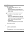
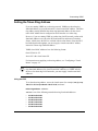
Using Site Manager
Caution: If you are configuring virtual routers on the IP interface used as the
Site Manager management console, do not add or modify a backup virtual
router before you create a master virtual router. Otherwise, you can lose
connectivity to the router when dynamically configuring virtual routers. To
prevent this, use local or remote mode when configuring a virtual router.
To configure a virtual router using Site Manager, complete the following tasks:
Site Manager Procedure
You do this
System responds
1. In the Configuration Manager window,
choose Protocols.
The Protocols menu opens.
2. Choose IP.
The IP menu opens.
3. Choose VRRP.
The IP VRRP Configuration Parameters
window opens.
4. Click on Add.
The Add Virtual Router window opens.
5. Set the following parameters:
• Primary IP Address
• Virtual Router ID
• Virtual Router IP Address
Click on Help or see the parameter
descriptions starting on page A-3.
6. Click on OK.
2-4
You return to the IP VRRP Configuration
Parameters window.
308647-14.00 Rev 00
Chapter 3
Customizing VRRP
To customize VRRP, use the information in the following sections:
Topic
Page
Disabling and Reenabling a Virtual Router
3-2
Changing the IP Address Backed Up by a Virtual Router
3-3
Setting the Priority of the Virtual Router
3-4
Setting the Advertisement Interval
3-6
Setting the Critical IP Interface Address
3-8
Enabling or Disabling IPX Backup
3-9
Enabling or Disabling IGMP Backup
3-11
Setting the Token Ring Address
3-13
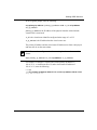
Caution: If you are configuring virtual routers on the IP interface used as the
Site Manager management console, do not add or modify a backup virtual
router before you create a master virtual router. Otherwise, you can lose
connectivity to the router when dynamically configuring virtual routers. To
prevent this, use local or remote mode when configuring a virtual router.
308647-14.00 Rev 00
3-1
Configuring VRRP Services
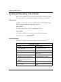
Disabling and Reenabling a Virtual Router
When you first configure a virtual router, the virtual router is enabled by default.
You can use the BCC or Site Manager to disable or reenable a virtual router.
Using the BCC
To disable a virtual router, access the virtual router (for example, box; ip; vrrp
192.41.31.21/2 vr-ip-address 192.41.31.22) and enter:
state disabled
To enable a virtual router, access the virtual router and enter:
state enabled
For example, to disable a virtual router, enter the following command:
vrrp/192.41.31.21/2# state disabled
vrrp/192.41.31.21/2#
Using Site Manager
To disable or reenable a virtual router, complete the following tasks:
Site Manager Procedure
You do this
System responds
1. In the Configuration Manager window,
choose Protocols.
The Protocols menu opens.
2. Choose IP.
The IP menu opens.
3. Choose VRRP.
The IP VRRP Configuration Parameters
window opens.
4. Click on a virtual router instance ID to
highlight it in the list of virtual routers.
The configuration that pertains to the
highlighted virtual router appears.
5. Set the Enable parameter. Click on Help
or see the parameter description on
page A-5.
6. Click on Apply.
7. Click on Done.
3-2
You return to the Configuration Manager
window.
308647-14.00 Rev 00
Customizing VRRP
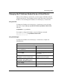
Changing the IP Address Backed Up by a Virtual Router
When you first configure a virtual router, you must supply an IP address that the
virtual router backs up. This IP address must be on the same subnet as the primary
IP address. You can change the IP address to be backed up by a virtual router.
Using the BCC
To change the IP address to be backed up by a virtual router, access the virtual
router (for example, box; ip; vrrp 192.41.31.21/2 vr-ip-address 192.41.31.22)
and enter:
vr-ip-address <vr_ip_address>
For example, to change the IP address, enter the following command:
vrrp/192.41.31.21/2# vr-ip-address 192.41.31.25
vrrp/192.41.31.21/2#
Using Site Manager
To change the IP address to be backed up by a virtual router, complete the
following tasks:
Site Manager Procedure
You do this
System responds
1. In the Configuration Manager window,
choose Protocols.
The Protocols menu opens.
2. Choose IP.
The IP menu opens.
3. Choose VRRP.
The IP VRRP Configuration Parameters
window opens.
4. Click on a virtual router instance ID to
highlight it in the list of virtual routers.
The configuration that pertains to the
highlighted virtual router appears.
5. Set the Virtual Router IP Address
parameter. Click on Help or see the
parameter description on page A-5.
6. Click on Apply.
7. Click on Done.
308647-14.00 Rev 00
You return to the Configuration Manager
window.
3-3
Configuring VRRP Services
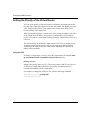
Setting the Priority of the Virtual Router
You can set the priority of the virtual router in relation to all virtual routers that
have the same virtual router ID and are on the same subnet. The higher you set the
value, the higher the priority of the virtual router, and the more likely it will
become primary if the master fails.
When you initially configure a virtual router, if the primary IP address is the same
as the virtual router IP address, the priority is automatically set to the highest
priority (255) and the virtual router becomes the master virtual router as soon as it
comes up.
The default priority for all backup virtual routers is 100. You can set the priority
for backup virtual routers from 1 to 254. If you assign more than one backup
virtual router the same priority, the VRRP router with the greater primary IP
address takes precedence.
Using the BCC
To change a virtual router’s priority, access the virtual router (for example, box;
ip; vrrp 192.41.31.21/2 vr-ip-address 192.41.31.22) and enter:
priority <integer>
integer is the priority from 1 to 255. (The priority values 0 and 255 are reserved
for the master virtual router; the master uses priority 0 to indicate that it is
releasing responsibility for the virtual router.)
For example, to change the priority to 254, enter the following command:
vrrp/192.41.31.21/2# priority 254
vrrp/192.41.31.21/2#
3-4
308647-14.00 Rev 00
Customizing VRRP
Using Site Manager
To set a virtual router’s priority, complete the following tasks:
Site Manager Procedure
You do this
System responds
1. In the Configuration Manager window,
choose Protocols.
The Protocols menu opens.
2. Choose IP.
The IP menu opens.
3. Choose VRRP.
The IP VRRP Configuration Parameters
window opens.
4. Click on a virtual router instance ID to
highlight it in the list of virtual routers.
The configuration that pertains to the
highlighted virtual router appears.
5. Set the Priority parameter. Click on Help
or see the parameter description on
page A-6.
6. Click on Apply.
7. Click on Done.
308647-14.00 Rev 00
You return to the Configuration Manager
window.
3-5
Configuring VRRP Services
Setting the Advertisement Interval
The advertisement interval is the number of seconds between transmissions of
VRRP advertisements from the master virtual router notifying all backup routers
that it is currently the master virtual router and is forwarding all traffic. You must
set the same advertisement interval for all VRRP routers having the same VRID
on the same LAN. The default advertisement interval is 1 second; however, you
can change the interval to a value from 1 through 255.
Using the BCC
To change a virtual router’s advertisement interval, access the virtual router (for
example, box; ip; vrrp 192.41.31.21/2 vr-ip-address 192.41.31.22) and enter:
advertisement-interval <integer>
integer is the interval, in seconds, from 1 to 255.
For example, to change the advertisement interval to 60, enter the following
command:
vrrp/192.41.31.21/2# advertisement-interval 60
vrrp/192.41.31.21/2#
3-6
308647-14.00 Rev 00
Customizing VRRP
Using Site Manager
To set the advertisement interval, complete the following tasks:
Site Manager Procedure
You do this
System responds
1. In the Configuration Manager window,
choose Protocols.
The Protocols menu opens.
2. Choose IP.
The IP menu opens.
3. Choose VRRP.
The IP VRRP Configuration Parameters
window opens.
4. Click on a virtual router instance ID to
highlight it in the list of virtual routers.
The configuration that pertains to the
highlighted router appears.
5. Set the Advertisement Interval
parameter. Click on Help or see the
parameter description on page A-6.
6. Click on Apply.
7. Click on Done.
308647-14.00 Rev 00
You return to the Configuration Manager
window.
3-7
Configuring VRRP Services
Setting the Critical IP Interface Address
The critical IP interface resides on the same router as a physical interface. The
state of the critical IP interface determines the state of the virtual router. If the
critical interface fails, the virtual router fails and the VRRP router with the next
highest priority becomes the master virtual router and begins routing traffic to its
destination.
Using the BCC
To specify a critical IP interface address, access the virtual router (for example,
box; ip; vrrp 192.41.31.21/2 vr-ip-address 192.41.31.22) and enter:
critical-ip-interface <critical_ip_address>
For example, to set the critical IP interface address, enter the following command:
vrrp/192.41.31.21/2# critical-ip-interface 192.41.31.76
vrrp/192.41.31.21/2#
Using Site Manager
To specify the critical IP interface address, complete the following tasks:
Site Manager Procedure
You do this
System responds
1. In the Configuration Manager window,
choose Protocols.
The Protocols menu opens.
2. Choose IP.
The IP menu opens.
3. Choose VRRP.
The IP VRRP Configuration Parameters
window opens.
4. Click on a virtual router instance ID to
highlight it in the list of virtual routers.
The configuration that pertains to the
highlighted router appears.
5. Set the Critical IP Interface parameter.
Click on Help or see the parameter
description on page A-7.
6. Click on Apply.
7. Click on Done.
3-8
You return to the Configuration Manager
window.
308647-14.00 Rev 00
Customizing VRRP
Enabling or Disabling IPX Backup
When the Internetwork Packet Exchange (IPX) protocol is configured on the same
physical interface as VRRP, you can enable IPX backup. When enabled, this
feature provides IPX backup when the virtual router is in the master state. In this
case, IPX configured on the physical interface uses the VRRP MAC address
instead of the physical MAC address. If the virtual router is in the backup state,
IPX is disabled.You can enable or disable IPX backup. By default, IPX backup is
disabled.
You can enable IPX Backup for one virtual router per interface.
Using the BCC
To enable IPX backup, access the virtual router (for example, box; ip; vrrp
192.41.31.21/2 vr-ip-address 192.41.31.22) and enter:
ipx-backup enabled
To disable IPX backup, access the virtual router and enter:
ipx-backup disabled
For example, to enable IPX backup, enter the following command:
vrrp/192.41.31.21/2# ipx-backup enabled
vrrp/192.41.31.21/2#
308647-14.00 Rev 00
3-9
Configuring VRRP Services
Using Site Manager
Site Manager Procedure
You do this
System responds
1. In the Configuration Manager window,
choose Protocols.
The Protocols menu opens.
2. Choose IP.
The IP menu opens.
3. Choose VRRP.
The IP VRRP Configuration Parameters
window opens.
4. Click on a virtual router instance ID to
highlight it in the list of virtual routers.
The configuration that pertains to the
highlighted router appears.
5. Set the IPX Backup parameter. Click on
Help or see the parameter description on
page A-7.
6. Click on Apply.
7. Click on Done.
3-10
You return to the Configuration Manager
window.
308647-14.00 Rev 00
Customizing VRRP
Enabling or Disabling IGMP Backup
When the Internet Group Management Protocol (IGMP) is configured on the
same physical interface as VRRP, you can enable IGMP backup. When enabled,
this feature provides IGMP backup when the virtual router is in the master state.
In this case, IGMP configured on the physical interface is enabled. If the virtual
router is in the backup state, IGMP is disabled. By default, IGMP backup is
disabled.
You can enable IGMP Backup for one virtual router per interface.
Using the BCC
To enable IGMP backup, access the virtual router (for example, box; ip; vrrp
192.41.31.21/2 vr-ip-address 192.41.31.22) and enter:
igmp-backup enabled
To disable IGMP backup, access the virtual router and enter:
igmp-backup disabled
For example, to enable IGMP backup, enter the following command:
vrrp/192.41.31.21/2# igmp-backup enabled
vrrp/192.41.31.21/2#
308647-14.00 Rev 00
3-11
Configuring VRRP Services
Using Site Manager
Site Manager Procedure
You do this
System responds
1. In the Configuration Manager window,
choose Protocols.
The Protocols menu opens.
2. Choose IP.
The IP menu opens.
3. Choose VRRP.
The IP VRRP Configuration Parameters
window opens.
4. Click on a virtual router instance ID to
highlight it in the list of virtual routers.
The configuration that pertains to the
highlighted router appears.
5. Set the IGMP Backup parameter. Click on
Help or see the parameter description on
page A-8.
6. Click on Apply.
7. Click on Done.
3-12
You return to the Configuration Manager
window.
308647-14.00 Rev 00
Customizing VRRP
Setting the Token Ring Address
If you are running VRRP on a token ring network, VRRP uses the token ring
functional address you provide instead of a virtual router MAC address. The token
ring address setting identifies the token ring functional address for the virtual
router MAC address that is configured on an IP interface over token ring.
However, if you are running VRRP on a token ring LANE network, packets with
functional addresses are sent to the BUS and treated as multicast or broadcast
frames, which causes the BUS to overload with user data frames. Since the BUS
has limited packet throughput, you must supply a virtual router MAC address
instead of a token ring functional address.
VRRP virtual MAC addresses have the following format:
00-00-5E-00-01-XX
where XX is the virtual router ID.
For instructions on supplying a token ring address, see “Configuring a Virtual
Router” on page 2-2.
Caution: For virtual routers running over token ring, you must supply token
ring functional addresses for virtual router MAC addresses, or VRRP will fail.
However, for token ring LANE networks, you must supply virtual router MAC
addresses.
Using the BCC
To set the token ring address, access the virtual router (for example, box; ip; vrrp
192.41.31.21/2 vr-ip-address 192.41.31.22) and enter:
token-ring-address <address>
address is one of the following unused token ring functional addresses:
•
•
•
•
•
•
308647-14.00 Rev 00
03-00-02-00-00-00
03-00-04-00-00-00
03-00-08-00-00-00
03-00-10-00-00-00
03-00-20-00-00-00
03-00-40-00-00-00
3-13
Configuring VRRP Services
•
•
•
•
•
03-00-80-00-00-00
03-00-00-01-00-00
03-00-00-02-00-00
03-00-00-04-00-00
03-00-00-08-00-00
For example, to set the token ring address, enter the following command:
vrrp/192.41.31.21/2# token-ring-address 03-00-80-00-00-00
vrrp/192.41.31.21/2#
Using Site Manager
To set the token ring address, complete the following tasks:
Site Manager Procedure
You do this
System responds
1. In the Configuration Manager window,
choose Protocols.
The Protocols menu opens.
2. Choose IP.
The IP menu opens.
3. Choose VRRP.
The IP VRRP Configuration Parameters
window opens.
4. Click on a virtual router instance ID to
highlight it in the list of virtual routers.
The configuration that pertains to the
highlighted router appears.
5. Set the Token Ring Address parameter.
Click on Help or see the parameter
description on page A-8.
6. Click on Apply.
7. Click on Done.
3-14
You return to the Configuration Manager
window.
308647-14.00 Rev 00
Appendix A
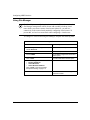
Site Manager Parameters
This appendix contains the Site Manager parameter descriptions for VRRP
services. You can display the same information using Site Manager online Help.
For information about the IP parameters you must set so that you can configure
VRRP, see Configuring IP, ARP, RIP, and OSPF Services.
For each parameter, this appendix provides the following information:
•
•
•
•
•
•
•
Parameter name
Configuration Manager menu path
Default setting
Valid parameter options
Parameter function
Instructions for setting the parameter
Management information base (MIB) object ID
The Technician Interface allows you to modify parameters by issuing set and
commit commands with the MIB object ID. This process is equivalent to
modifying parameters using Site Manager. For more information about using the
Technician Interface to access the MIB, see Using Technician Interface Software.
Caution: The Technician Interface does not verify the validity of your
parameter values. Entering an invalid value can corrupt your configuration.
308647-14.00 Rev 00
A-1
Configuring VRRP Services
Add Virtual Router Parameters
The VRRP parameters in the Add Virtual Router window (Figure A-1) let you
establish a virtual router on an IP interface.
To Be Supplied
Figure A-1.
Add Virtual Router Window
To access the Add Virtual Router window, complete the following tasks:
Site Manager Procedure
You do this
System responds
1. In the Configuration Manager window,
choose Protocols.
The Protocols menu opens.
2. Choose IP.
The IP menu opens.
3. Choose VRRP.
The IP VRRP Configuration Parameters
window opens.
4. Click on Add.
The Add Virtual Router window opens.
The parameter descriptions follow.
A-2
308647-14.00 Rev 00
Site Manager Parameters
Parameter: Primary IP Address
Path:
Default:
Options:
Function:
Configuration Manager > Protocols > IP > VRRP > Add
None
Any valid IP address in dotted-decimal notation
Identifies the IP address of the physical interface. The router lists this IP address
as the source in VRRP advertisements sent by the virtual router.
Instructions: Ensure that the primary IP address and the virtual router IP address are on the
same subnet.
MIB Object ID: 1.3.6.1.4.1.18.3.5.3.25.1.1.4
Parameter: Virtual Router ID
Path:
Default:
Options:
Function:
Configuration Manager > Protocols > IP > VRRP > Add
None
1 to 255
Identifies the virtual router’s ID (VRID). The router uses this number to
calculate the MAC address. The VRID must be unique on the LAN segment.
Instructions: Enter the ID of the virtual router.
MIB Object ID: 1.3.6.1.4.1.18.3.5.3.25.1.1.5
Parameter: Virtual Router IP Address
Path:
Default:
Options:
Function:
Instructions:
Configuration Manager > Protocols > IP > VRRP > Add
None
Any valid IP address in dotted-decimal notation
Identifies the IP address that the virtual router backs up.
Ensure that the primary IP address and the virtual router IP address are on the
same subnet. If the virtual router IP address is the same as the primary IP
address, then this VRRP router, when operating, will always be the master
virtual router.
MIB Object ID: 1.3.6.1.4.1.18.3.5.3.25.1.1.6
308647-14.00 Rev 00
A-3
Configuring VRRP Services
VRRP Configuration Parameters
The VRRP configuration parameters let you customize a virtual router. You
access these parameters from the IP VRRP Configuration Parameters window
(Figure A-2).
Figure A-2.
IP VRRP Configuration Parameters Window
To access the IP VRRP Configuration Parameters window, complete the
following tasks:
Site Manager Procedure
A-4
You do this
System responds
1. In the Configuration Manager window,
choose Protocols.
The Protocols menu opens.
2. Choose IP.
The IP menu opens.
308647-14.00 Rev 00
Site Manager Parameters
Site Manager Procedure (continued)
You do this
System responds
3. Choose VRRP.
The IP VRRP Configuration Parameters
window opens.
4. Click on a virtual router instance ID to
highlight it in the list of virtual routers.
The configuration that pertains to the
highlighted virtual router appears.
The parameter descriptions follow.
Parameter: Enable
Path:
Default:
Options:
Function:
Instructions:
Configuration Manager > Protocols > IP > VRRP
Enable
Enable | Disable
Enables or disables a virtual router on an interface.
Select Enable to enable a virtual router on an interface. Select Disable to disable
a virtual router on an interface.
MIB Object ID: 1.3.6.1.4.1.18.3.5.3.25.1.1.2
Parameter: Virtual Router IP Address
Path:
Default:
Options:
Function:
Instructions:
Configuration Manager > Protocols > IP > VRRP
None
Any valid IP address in dotted-decimal notation
Identifies the IP address of the interface that the virtual router backs up.
Enter the IP address that you want the virtual router to back up. Ensure that the
primary IP address and the virtual router IP address are on the same subnet. If
the virtual router IP address is the same as the primary IP address, Site Manager
automatically sets the priority to 255 so that this VRRP router will always be the
master virtual router.
MIB Object ID: 1.3.6.1.4.1.18.3.5.3.25.1.1.6
308647-14.00 Rev 00
A-5
Configuring VRRP Services
Parameter: Priority
Path:
Default:
Options:
Function:
Configuration Manager > Protocols > IP > VRRP
100
1 to 255
Specifies the priority of the virtual router with respect to all virtual routers on
the IP interface.
Instructions: Enter a priority from 1 to 254. The higher the value you specify, the higher the
priority of the virtual router. Site Manager automatically supplies a priority of
100 for all backup virtual routers. If you set the primary IP address to the IP
address of the physical interface, Site Manager sets the priority to 255.
MIB Object ID: 1.3.6.1.4.1.18.3.5.3.25.1.1.8
Parameter: Advertisement Interval
Path:
Default:
Options:
Function:
Configuration Manager > Protocols > IP > VRRP
1 (s)
1 to 255
Specifies the interval, in seconds, between the transmission of VRRP
advertisements from the primary virtual router.
Instructions: Enter a value from 1 to 255 seconds.
MIB Object ID: 1.3.6.1.4.1.18.3.5.53.25.1.1.9
A-6
308647-14.00 Rev 00
Site Manager Parameters
Parameter: Critical IP Interface
Path:
Default:
Options:
Function:
Configuration Manager > Protocols > IP > VRRP
0.0.0.0 (none)
Any valid IP address in dotted-decimal notation
Identifies an IP address that determines whether the virtual router assumes the
role of the master virtual router and is responsible for forwarding traffic. If the
critical IP address is operating, then the virtual router forwards traffic. If the
critical IP address is down, then a backup virtual router assumes the
responsibilities of the master virtual router and forwards traffic. The critical IP
address must be on the same router as the primary IP address.
Instructions: Specify an IP address on the same router where the primary IP address resides.
MIB Object ID: 1.3.6.1.4.1.18.3.5.53.25.1.1.10
Parameter: IPX Backup
Path:
Default:
Options:
Function:
Configuration Manager > Protocols > IP > VRRP
Disable
Enable | Disable
Enables or disables IPX backup when IPX is configured on the same physical
interface as VRRP. When enabled, this feature provides IPX backup when the
virtual router is in the master state. In this case, IPX configured on the physical
interface uses the VRRP MAC address instead of the physical MAC address. If
the virtual router is in the backup state, IPX is disabled.
Instructions: Select Enable to enable IPX backup on the virtual router. Select Disable to
disable IPX backup on the virtual router.
MIB Object ID: 1.3.6.1.4.1.18.3.5.53.25.1.1.11
308647-14.00 Rev 00
A-7
Configuring VRRP Services
Parameter: IGMP Backup
Path:
Default:
Options:
Function:
Configuration Manager > Select Protocols > IP > VRRP
Disable
Enable | Disable
Enables or disables IGMP backup when IGMP is configured on the same
physical interface as VRRP. When enabled, this feature provides IGMP backup
when the virtual router is in the master state. In this case, IGMP configured on
the physical interface is enabled. If the virtual router is in the backup state,
IGMP is disabled.
Instructions: Select Enable to enable IGMP backup on the virtual router. Select Disable to
disable IGMP backup on the virtual router.
MIB Object ID: 1.3.6.1.4.1.18.3.5.53.25.1.1.12
Parameter: Token Ring Address
Path: Configuration Manager > Select Protocols > IP > VRRP
Default: None
Options: Use one of the following unused token ring functional addresses:
03-00-02-00-00-00
03-00-04-00-00-00
03-00-08-00-00-00
03-00-10-00-00-00
03-00-20-00-00-00
03-00-40-00-00-00
03-00-80-00-00-00
03-00-00-01-00-00
03-00-00-02-00-00
03-00-00-04-00-00
03-00-00-08-00-00
Function: Identifies the token ring functional address for the virtual router ID MAC
address that is configured on an IP interface over token ring.
Instructions: Specify a unique functional token ring address. You must specify a token ring
functional address for virtual routers on an IP interface over token ring;
otherwise, VRRP will not function.
MIB Object ID: 1.3.6.1.4.1.18.3.5.53.25.1.1.13
A-8
308647-14.00 Rev 00
Appendix B
Monitoring VRRP Using the BCC show Commands
This appendix describes how to use the BCC show command to obtain VRRP
statistical data from the management information base (MIB). The type and
amount of data displayed depend on the specific settings you want to view. This
appendix includes descriptions of the following show commands:
Command
Page
show vrrp critical-ip-addresses
B-2
show vrrp mac-addresses
B-2
show vrrp summary
B-3
Online Help for show Commands
To display a list of command options, enter show vrrp ? at any BCC prompt. To
learn more about any show vrrp command option and its syntax, use the question
mark (?) command as follows:
Example
bcc> show vrrp?
critical-ip-addresses
mac-addresses
bcc> show vrrp critical-ip-addresses?
summary
show vrrp critical-ip-addresses [-vrid <arg>] [-primary-ip-address <arg>]
bcc>
308647-14.00 Rev 00
B-1
Configuring VRRP Services
show vrrp critical-ip-addresses
The show vrrp critical-ip-addresses command displays the local IP interface (critical IP
address) associated with a specific VRRP virtual router or all VRRP virtual routers. This
command allows for the following command filters (flags) and filter arguments:
-primary-ip-address
<primary_ip_address>
Displays information about the virtual router associated with the IP
address of the physical interface.
-vrid <vrid>
Displays information about the virtual router associated with the
specified virtual router identifier.
The output includes the following information:
Primary IP Address
IP address of the physical interface with which the virtual router is
associated.
VRID
Virtual router identifier configured in the range of 1 to 255.
Virtual IP Address
IP address that the virtual router backs up.
Critical IP Address
IP address that determines whether the virtual router assumes the
role of the master virtual router and is responsible for forwarding
traffic. If the critical IP address is operating, then the virtual router
forwards traffic. If the critical IP address is down, then a backup
virtual router assumes the responsibilities of the master virtual
router and forwards traffic.
show vrrp mac-addresses
The show vrrp mac-addresses command displays the virtual media access control
(MAC) address and token ring address associated with a specific VRRP virtual router or
all VRRP virtual routers.
This command allows for the following command filters (flags) and filter arguments:
B-2
-primary-ip-address
<primary_ip_address>
Displays information about the virtual router associated with the IP
address of the physical interface.
-vrid <vrid>
Displays information about the virtual router that corresponds to the
specified virtual router identifier.
308647-14.00 Rev 00
Monitoring VRRP Using the BCC show Commands
The output includes the following information:
Primary IP Address
IP address of the physical interface with which the virtual router is
associated.
VRID
Virtual router identifier configured in the range of 1 to 255.
Virtual IP Address
IP address that the virtual router backs up.
VRRP Virtual MAC Address
Virtual router MAC address that is configured on an IP interface over
token ring
Token Ring Func. Address
Token ring functional address for the VRRP virtual MAC address.
show vrrp summary
The show vrrp summary command displays the state, advertisement interval, and priority
for a specific VRRP virtual router or all VRRP virtual routers. This command allows for
the following command filters (flags) and filter arguments:
-primary-ip-address
<primary_ip_address>
Displays information about the virtual router associated with the IP
address of the physical interface.
-vrid <vrid>
Displays information about the virtual router that corresponds to the
specified virtual router identifier.
The output includes the following information:
Primary IP Address
IP address of the physical interface with which the virtual router is
associated.
VRID
Virtual router identifier configured in the range of 1 to 255.
Virtual IP Address
IP address that the virtual router backs up.
VRRP Operational State
Current state of the virtual router: initialize, master, or backup.
Advertisement Interval
The interval, in seconds, between the transmission of VRRP
advertisements from the primary virtual router.
Priority
The priority (from 1 to 255) of the virtual router with respect to all
virtual routers on the IP interface.
308647-14.00 Rev 00
B-3
Glossary
advertisement
An IP packet periodically broadcast by the master virtual router to prevent a
backup virtual router from becoming the master virtual router.
backup virtual router
One of a set of VRRP routers available to become the master virtual router. A
router may be either the master virtual router or the backup virtual router for
many virtual routers.
critical IP interface
A local IP interface associated with a virtual router. When the state of this
interface changes, the virtual router switches roles. For example, if you
designate IP address 1.1.1.1 as the critical IP address for virtual router 1 on
router B, and IP address 1.1.1.1 fails, then virtual router 1 on router B is no
longer the master virtual router, and a backup virtual router becomes the
master virtual router.
master virtual router
The VRRP router that both assumes responsibility for forwarding data packets
received at the MAC address associated with its virtual router, and also
answers ARP requests for its IP address. A router may be the master virtual
router or the backup virtual router for many virtual routers.
primary IP address
The real IP interface address used as the source IP address for the IP packets
carrying advertisements.
priority
The value that determines whether a virtual router serves as the master or
backup virtual router. The VRRP router with the highest priority becomes the
master virtual router. The value 255 is reserved for the router that owns the IP
address associated with the virtual router. The value 0 is reserved for the
master virtual router to indicate that it is releasing responsibility for the virtual
router. The values 1 through 254 are available for VRRP routers backing up
the virtual router. The default priority is 100.
virtual MAC address
A unicast MAC address associated with each virtual router and used as the
source MAC address for VRRP advertisements. The master virtual router uses
this address instead of its physical MAC address in all communication.
308647-14.00 Rev 00
Glossary-1
Configuring VRRP Services
virtual router
A software-defined object managed by VRRP that corresponds to an IP
address on a LAN segment. A virtual router typically exists on multiple VRRP
routers. One VRRP router acts as the master virtual router for this IP address,
and the others act as backup virtual routers.
VRID
The virtual router identifier configured in the range of 1 through 255. The
VRID must be unique within the subnet.
VRRP router
A router running the Virtual Router Redundancy Protocol. A VRRP router
may participate in one or more virtual routers.
Glossary-2
308647-14.00 Rev 00
Index
A
acronyms, xi
I
adding a virtual router, 3-3
IGMP Backup parameter, A-8
Advertisement Interval parameter, A-6
IGMP backup, enabling or disabling, 3-11
advertisement interval, setting, 3-6
IP address to be backed up, assigning, 3-3
B
IP multicast datagrams, 1-2
IPX Backup parameter, A-7
backup virtual router, defined, 1-2
IPX backup, enabling or disabling, 3-9
BCC
show commands, B-1
starting VRRP services, 2-2
M
MAC address, 1-2, 2-2
C
configuring a virtual router, 2-1
conventions, text, x
master virtual router, defined, 1-2
messaging, 1-2
P
Critical IP Interface parameter, A-7
critical IP interface, specifying, 3-8
primary IP address, 2-2
customer support, xii
Primary IP Address parameter, A-3
priority of virtual routers, defined, 1-2
D
disabling
a virtual router, 3-2
IGMP backup, 3-11
IPX backup, 3-9
Priority parameter, A-6
priority, setting, 3-4
product support, xii
protocol messaging, defined, 1-2
publications
hard copy, xii
E
R
Enable parameter, A-5
enabling
a virtual router, 3-2
IGMP backup, 3-11
IPX backup, 3-9
308647-14.00 Rev 00
redundancy services, planning, 1-3
router redundancy, characteristics, 1-3
Index-1
S
show commands, online Help for, B-1
show vrrp critical-ip-addresses command, B-2
show vrrp mac-addresses command, B-2
show vrrp summary command, B-3
support, Nortel Networks, xii
T
technical publications, xii
technical support, xii
text conventions, x
Token Ring Address parameter, A-8
token ring address, setting, 3-13
token ring functional address, 3-13
V
virtual router
configuring, 2-1
disabling, 3-2
enabling, 3-2
virtual router ID (VRID), assigning, 2-2
Virtual Router ID parameter, A-3
Virtual Router IP Address parameter, A-3, A-5
virtual router IP address, assigning, 2-2
VRRP advertisements, 3-6
Index-2
308647-14.00 Rev 00