1
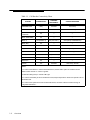
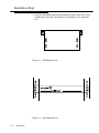
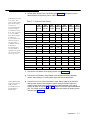
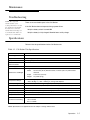
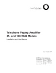
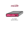
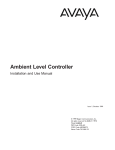
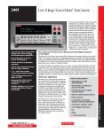
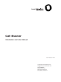
Call Stacker
Installation and Use Manual
Issue 1, October 1999
© 1999 Bogen Communications, Inc.
All rights reserved. 54-2025-01 9910
Model: LULCST
PEC Code: 5325-150
COM Code: 408184018
Select Code: 701-000-118
© 1999 Bogen Communications, Inc.
All Rights Reserved. Printed in U.S.A.
Notice
Every effort was made to ensure that the information in this
guide was complete and accurate at the time of printing.
However, information is subject to change.
FCC Statement (Part 15) - Radio Frequency
Interference
The Call Stacker generates and uses radio frequency energy
and if not installed and used in strict accordance with the manufacturer's instructions, may cause interference to radio and
television reception. Testing is being conducted for compliance
with the limits for a Class B device in accordance with the
specifications in Part 15 of the FCC Rules and Canadian
D.O.C. regulations. This testing is designed to provide reasonable protection against such interference. However, there is no
guarantee that interference will not occur in a particular installation. If this equipment does cause interference to radio or
television reception, which can be determined by turning the
Call Stacker unit off and on, the user is encouraged to try to
correct the interference by one or more of the following
measures:
- Reorient the radio or TV receiving antenna.
- Relocate the Call Stacker unit with respect to the radio or
TV receiver or vice-versa.
- Plug the Call Stacker unit into a different outlet so that it and
the radio or TV receiver are on different branch circuits.
If necessary, the user should consult the dealer or an experienced radio/television technician for additional suggestions. The
user may find the following booklet, "How To Identify and
Resolve Radio-TV Interference Problems," helpful. This booklet
was prepared by the Federal Communications Commission
(FCC) and is available from the U.S. Government Printing
Office, Washington, DC 20402. Stock order No. 004-00000345-4.
Federal Communications Commission (FCC)
Statement (Part 68)
This equipment is component registered with the Federal
Communications Commission (FCC) in accordance with Part
68 of its rules. In compliance with the rules, be advised of the
following:
Registered equipment may not be used with Coin Telephone
Lines. Equipment may be used with Party Lines in areas where
state tariffs permit such connections and when equipment is
adaptable for such service.
This equipment is registered as follows:
Registration Number - F4PCAN-20988-AN-N
Ringer Equivalence - 1.6B
If trouble is experienced, the equipment should be disconnected from the interface to determine if this equipment, or the
telephone line is the trouble source. If the equipment is determined to be malfunctioning, it should not be reconnected until
repairs are effected.
Repairs to this equipment, other than routine repairs, can be
made only by the manufacturer or its authorized agents.
If the equipment causes harm to the telephone network, the
local telephone company may temporarily discontinue your
service and, if possible, notify you in advance. If advance notice
is not practical, you will be notified as soon as possible. You will
be given the opportunity to correct the problem and informed
of your right to file a complaint with the FCC.
The local telephone company may make changes in its facilities,
operations, or procedures that could affect the proper functioning of your equipment. If they do, you will be given adequate notice in writing to allow you an opportunity to maintain uninterrupted telephone service.
Trademarks
Centrex is a registered trademark of Lucent Technologies.
Important Safety Information
Always follow these basic safety precautions when installing
and using the system:
1. Read and understand all instructions.
2. Follow all warnings and instructions marked on the product.
3. DO NOT block or cover the ventilation slots and openings.
They prevent the product from overheating. DO NOT place
the product in a separate enclosure or cabinet, unless proper
ventilation is provided.
4. Never spill liquid on the product or drop objects into the
ventilation slots and openings. Doing so may result in serious
damage to the components.
5. Repair or service must be performed by a factory authorized repair facility.
6. The product is provided with a UL-CSA approved, 3-wire
ground type plug. This is a safety feature. DO NOT defeat the
safety purpose of the grounding type plug. DO NOT staple or
otherwise attach the AC power supply cord to building surfaces.
7. DO NOT use the product near water or in a wet or damp
place (such as a wet basement).
8. DO NOT use extension cords. The product must be
installed within 6 feet of a grounded outlet receptacle.
9. DO NOT install telephone wiring during a lightning storm.
10. DO NOT install telephone jacks in a wet location unless
the jack is specifically designed for wet locations.
11. Never touch uninsulated wires or terminals, unless the line
has been disconnected at the paging or controller interface.
12. Use caution when installing or modifying paging or control
lines.
Support Information
Paging systems integrated with small phone systems such as
Merlin Legend and Partner are supported by the National
Service Assistance Center (NSAC). The main number for the
NSAC is 800-628-2888. Paging systems integrated with large
switches such as the DEFINITY G3 are supported by the
Technical Service Center (TSC). The main number for the TSC
is 800-242-2121.
Domestic and International Approvals
CSA Certified LR55025; NRTL/C Certified; FCC Part 15 and
Part 68.
Contents
1.
Overview1-1
Introduction
Before You Start
n
n
2.
Installation
2-1
Installation Steps
n
3.
1-2
1-3
2-2
Operation3-1
n
n
n
Operation
Maintenance
Specifications
3-2
3-5
3-5
iii
This page intentionally left blank.
iv
Overview
Contents
Introduction
1-2
Before You Start
1-3
Overview
1-1
Introduction
The Call Stacker is a microprocessor based audio
recording and announcement system. The Call Stacker is used in conjunction
with a paging system to provide buffered announcement play to the paging
system.
Figure 1-1. Call Stacker Unit
The Call Stacker features 5 Input Station (recording) channels, a single Page
Output channel and 3 minutes of recording time.
Up to 5 announcements can be recorded simultaneously, virtually eliminating
frustrating delays encountered when accessing the paging system. The recorded
announcements are queued in order so the first announcement recorded that has
hung up, plays first, followed by the second announcement, etc.
The Call Stacker allows users to verify their announcements before they play to
the paging system. If a user is not content with their recorded announcement,
they can re-record it repeatedly until they are satisfied.
The Call Stacker's Page Output channel interfaces to the paging system's control
unit. Once an announcement is recorded, the Call Stacker plays the
announcement over the Page Output channel to the paging system. While the
recorded announcement is playing, the Page Output channel provides a contact
closure to the paging system.
Once the complete recorded announcement plays to the paging system, it is
erased from the Call Stacker, freeing up the recording time for new
announcements.
The Call Stacker can be configured to record and play back paging zone
selection signals. Between 2 and 4 DTMF digits can be entered prior to recording
an announcement which, upon output, precede the recorded announcement and
select the paging system's paging zone.
NOTE: Associated
equipment would need
to be powered by an
uninterrupted power
supply.
1-2
Overview
The Call Stacker is equipped with battery backup which allows it to operate for up to
two hours, from a fully charged battery, if a power failure occurs.
Before You Start
Before installing your system, read and understand the safety instructions on
page ii (inside front cover). Be sure you have all the necessary parts, tools, and
test equipment, listed below.
1. Read important Safety Information on Page ii.
2. Check Shipping Container Contents.
n Call Stacker Unit
n Mounting Hardware (screws and brackets)
n Power Cord
n This Installation and Use Guide
3. Have Required Tools
The following tools are required for the installation of the hardware and cabling.
n Phillips screwdriver (small and large)
n Standard blade screwdriver (small and large)
n Wire strippers (24 AWG - 12 AWG)
n Telephone test set
n Tone out circuit tester (optional, for troubleshooting)
n Volt-ohm Meter (optional, for troubleshooting)
n 4 wood screws, if mounted on wall
4. Verify Interface Compatibility with Telephone System and Paging System (see
Table 1-1 on the next page).
Overview 1-3
Table 1-1. Call Stacker Connectivity Chart.
CONNECTIVITY
FORWARD
DISCONNECT
STATION GROUPING
Yes (Release 2 or
later)
Standard
Hunt Group
PARTNER II
Yes
Standard
Hunt Group
Spirit 308/616,
1224/2448
No
—
—
Merlin 206/410/820
No
—
—
Yes (Release 3)
Yes (see note 1)
GCD (Group Call Distribution)
Merlin Plus
No
—
—
Merlin 1030/3070
No
—
—
Legend
Yes
Yes (see note 2)
Calling Group, Circular
System 25
Yes
Standard
Station Hunting, Circular
Definity
Yes
Yes (see note 3)
UCD (Uniform Call Distribution)
System 85
Yes
Yes (see note 4)
UCD (Uniform Call Distribution)
Dimension
No
—
—
Horizon
Yes
Standard
Hunt Group, Circular
SYSTEM
PARTNER PLUS
Merlin II
NOTE:
1. In order for the Merlin II to send a forward disconnect, set the station option for AA/VMS. The 012
station module must be “F” version or greater.
2. Make the Calling Group a “Generic VMI” type.
3. In order for the Definity to send a forward disconnect, Adjunct Supervision needs to be optioned “Yes” at
the station level.
4. In order for the System 85 to send a forward disconnect, the Class of Service needs to change to
“Origination Restriction.”
1-4
Overview
Installation
Contents
Installation Steps
2-2
Installation
2-1
Installation Steps
1. Attach the reversible brackets to the Call Stacker using the 6-32 x 3/8" screws
provided, then secure the Call Stacker to a back board or into an equipment
rack.
Figure 2-1. Wall Mounted Unit
Figure 2-2. Rack Mounted Unit
2-2
Installation
2. Set the option switch on the Call Stacker (see Figure 3-1 on page 3-2) for the
desired system configuration (refer to Table 2-1).
NOTE: When the switch
#7 is “OFF”, there
will be no delay in time
from when the paging
system zone is
accessed until the time
when the message is
sent. When the switch
#7 in “ON”, there will
be a 2 second delay
from when the paging
system/zone is
accessed until the time
when the message is
sent. The delay is
installed in order for a
Confirmation/
Pre-announcement
tone (if available or
optioned) to be played
over the system before
the message is sent.
Table 2-1. Option Switch Setting.
SET
SET
SET
SET
SET
SET
SET
SWITCH SWITCH SWITCH SWITCH SWITCH SWITCH SWITCH
# 1 TO
# 2 TO
# 3 TO
# 4 TO
# 5 TO
# 6 TO
# 7 TO
Number of DTMF Digits in Zone Code
0
ON
ON
—
—
—
—
—
2
OFF
ON
—
—
—
—
—
3
ON
OFF
—
—
—
—
—
4
OFF
OFF
—
—
—
—
—
—
—
ON
ON
—
—
—
Voice Prompts
None
English only
—
—
OFF
ON
—
—
—
Spanish only
—
—
ON
OFF
—
—
—
English/Spanish
—
—
OFF
OFF
—
—
—
Length of Recording Cut Off (when user hangs up during recording)
None
—
—
—
—
ON
ON
—
0.25 sec
—
—
—
—
OFF
ON
—
0.50 sec
—
—
—
—
ON
OFF
—
0.75 sec
—
—
—
—
OFF
OFF
—
—
—
—
—
SEE NOTE
Confirmation or Pre-Announcement Tone
2 Second Delay
—
—
3. Connect the Call Stacker to the paging system (see Figure 2-4):
NOTE: PBX and KTS
stations must have the
ability to send a
forward disconnect to
the Call Stacker's
Station inputs.
■
Connect the Call Stacker's Page Output to the attendant override (attendant
access control leads) or incoming alarm signal from the paging system.
■
Connect one or more of the Call Stacker's Input Station channels to PBX/KTS
analog station inputs on the telephone system through FCC/DOC approved
modular jacks.Connect the Call Stacker's Page Output channel to the paging
system as shown in Figures 2-4 and 2-5 through an FCC/DOC approved modular
jack. The control contact signal is used to secure and release the paging system
controller (see figure 2-3).
Installation
2-3
Figure 2-3. Page Output Channel Connection of Call Stacker
Figure 2-4. Connection to Lucent LUPCM Zone Paging System
Figure 2-5. Connection to Telephone Paging Amplifier
2-4
Installation
4. Connect the detachable power supply cord between a 110/120 VAC outlet and the
Call Stacker and verify the Power LED illuminates.
5. Turn the battery switch ON.
Installation
2-5
This page intentionally left blank.
2-6
Installation
Operation
Contents
Operation
3-2
■
Controls and Indicators
3-2
■
Recording Announcements
3-3
■
Announcement Playback
3-4
Maintenance
■
Troubleshooting
Specifications
3-5
3-5
3-5
Operation
3-1
Operation
Controls and Indicators
Figure 3-1. Rear Panel Detail
Table 3-1. Rear Panel Description
ITEM
DESCRIPTION
Power On LED
Illuminates when power is supplied to the Call Stacker.
Pause Override Control
Input
Enables/disables the Page Output channel. When a contact
closure (a short) between the two terminals is detected, the
Call Stacker terminates the outgoing announcement (if any),
requeues it and disables the Page Output channel. When
the contact closure is removed, the Page Output channel is
re-enabled and the terminated announcement plays to the
paging system in its entirety (see note below).
Input Station
(record) Channels
PBX and KTS analog station interfaces (tip/ring pairs) to the
Public Telephone Network, a PABX or a Key System.
Page Output Channel
Audio and control contact signals to the paging system as
shown in figure 2-3. Between outgoing announcements the
control contact opens for a minimum of 250 msec. to release
the paging system controller.
Option Switch
See table 2-1.
Battery Switch
Enables/disables battery backup. Turn the switch ON to
enable the battery backup.
Power Input
110/120 VAC, 60Hz, power input
NOTE: The Input Station channels continue to operate when a contact closure is detected. Recorded
announcements are held in a queue and play out sequentially (first in, first out) when the contact
closure is removed.
3-2
Operation
Recording Announcements
Voice Prompts
Enabled
1. Dial up the input station connected to the Call Stacker. The Call Stacker answers
the trunk and responds “Enter zone code (Marque el codigo de la zona)”. Proceed
to step 2.
NOTE: If the number of
digits in the paging
zone is set to 0 (see
Table 2-1), the Call
Stacker answers the
trunk and responds
“Start recording, press
the pound key to end or
hang up (Empieze a
grabar el mensage,
para terminar la
grabación cuelge o
marque la tecla de
numero)” followed by a
high tone. Skip step 2
and proceed to step 3.
2. Enter a DTMF tone sequence using the telephone keypad to select a paging
zone.
IMPORTANT: If all the
recording time is used
up, the Call Stacker
answers the trunk and
responds with “No
recording time
available (No hay
tiempo de grabación
disponible)” or
“Message not
recorded (No hay
mensajes grabados)”
then disconnects. If this
occurs wait a few
seconds before reattempting to record
the announcement.
3. Record the announcement. To end recording, either:
■
Once the required number of DTMF digits (see Table 2-1) are entered, the Call
Stacker responds “Start recording, press the pound key to end or hang up
(Empieze a grabar el mensage, para terminar la grabación cuelge o marque la
tecla de numero)” followed by a high tone. Proceed to step 3.
■
Hang up to enter the recorded announcement into the queue, or
■
Press the “#” key to hear the recorded announcement. The Call Stacker
responds “Hang up if finished, press zero to re-record or stay on the line to
review your message (Cuando termine de grabar cuelge, marque la tecla cero
para regrabar, o siga en la linea para escuchar el mensage grabado)”, plays
back the recorded announcement and then responds “Hang up if finished,
press zero to re-record (Cuando termine de grabar cuelge, marque la tecla
cero para regrabar)”. Press the “0” key to re-record the announcement and
return to step 2 or hang up to accept the announcement and enter it into the
queue.
NOTE: Press the “#”
key while the voice
prompts are playing to
interrupt (and skip)
them.
Operation
3-3
Voice Prompts
Disabled
1. Dial up the input station connected to the Call Stacker and wait for the Call
Stacker to answer the trunk and respond with a high tone. Proceed to step 2.
NOTE: If the number of
digits in the paging
zone is set to 0 (see
Table 2-1), skip step 2
and proceed to step 3.
2. Enter a DTMF tone sequence using the telephone keypad to select a paging
zone. Once the required number of DTMF digits (see table 2-1) are entered, the
Call Stacker responds with a high tone. Proceed to step 3.
Important: If all the
recording time is used
up, the Call Stacker
responds with two
consecutive low tones
then disconnects. If this
occurs your
announcement has not
been recorded. Wait a
few seconds before reattempting to record
the announcement.
3. Record the announcement. To end recording, either:
■
Hang up to enter the recorded announcement into the queue, or
■
Press the “#” key to hear the recorded announcement. The Call Stacker
responds with a high tone, plays back the recorded announcement and then
responds with a second high tone. Press the “0” key to re-record the
announcement and return to step 2 or hang up to accept the announcement
and enter it into the queue.
Announcement Playback
Once a recorded announcement is entered into the queue, the Call Stacker
immediately closes the control contact on the Page Output channel to access the
paging system controller.
The Call Stacker then plays out the recorded DTMF sequence to select the
paging zone followed by the recorded announcement.
At the end of the announcement the Call Stacker erases the announcement and
opens the control contact on the Page Output channel to release the paging
system controller.
NOTE: If more than
one announcement is
in the queue, the
control contact
remains open for a
minimum of 250 msec.
3-4
Operation
Important: If at any time a contact closure is detected on the Pause Override Control
Input, the Call Stacker immediately terminates the outgoing announcement and
requeues it for playback in its entirety once the contact closure is removed.
Maintenance
Troubleshooting
NOTE: The suggested
reliable lifetime of the
rechargeable battery used in
the equipment is 36 months.
To ensure the system has
reliable battery backup, it is
recommended the battery be
replaced every 30 months.
There are no serviceable parts in the Call Stacker:
If the Call Stacker does not operate during a power failure:
n
Verify the battery switch is turned ON.
n
Verify the battery is fully charged. Allow 48 hours to fully charge.
Specifications
Table 3-2 lists the specifications for the Call Stacker unit.
Table 3-2. Call Stacker Unit Specifications
SPECIFICATION
DESCRIPTION
Recording Time
n
3 minute base unit.
Input Lines
n
5 analog station ports.
Output Lines
n
1 page output channel.
Number of stacked
Announcements
n
30 individual announcements.
Power Supply
n
115 VAC, 60 Hz.
n
Height:
1.75 inches (4.4 cm).
n
Width:
16.25 inches (41cm) without brackets, 19 inches (48.3 cm) with brackets
attached.
n
Depth:
9.25 inches (23.5 cm).
n
Weight:
13 pounds (6 kg).
n
0 to +40 deg. C. (32 to 104 deg. F.) operational.
n
–40 to +66 deg. C. (–40 to +150 deg. F.) storage and shipment.
Humidity Range:
n
5% to 95% (non-condensing) storage/shipment and operation.
Altitude:
n
Sea level to 10,000 ft. operational (1048 to 648 millibars) 40,000 ft. max. shipment.
Environmental
n
Locate in an area free of excess moisture, corrosive gases, dust, and chemicals.
Battery Backup
n
Allows up to two hours of operation during a power failure. Total charge time 48 hours.
Frequency Response
n
200 Hz to 3.4 kHz ( ±3 dB).
Output Level
n
–9 dBm.
n
0.3 A / 60 VDC
n
1.0 A / 24 VDC
n
0.5 A / 120 VAC
Dimensions and Weight
Temperature Range:
Control Contact Rating
NOTE: Specifications are approximate and are subject to change without notice.
Operation
3-5