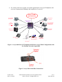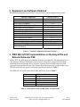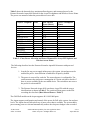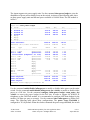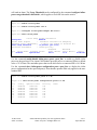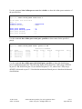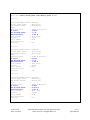
1
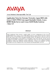
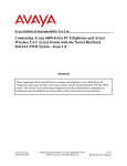
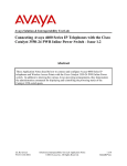
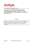
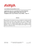
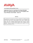
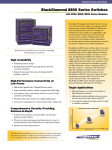
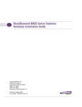
Avaya Solution & Interoperability Test Lab
Application Notes for Extreme Networks Aspen 8810 PoE
Module with Avaya 4600 Series IP Telephones and Avaya
Wireless Access Points - Issue 1.0
Abstract
These Application Notes describe how to configure the Power over Ethernet module of the
Extreme Networks Aspen 8810 to provide inline power for Avaya 4600 Series IP telephones
and Avaya Wireless Access Points. The various Avaya powering arrangements are shown and
the administration commands for displaying and controlling the powering status of the switch
ports are demonstrated. All test cases completed successfully. Information in these Application
Notes has been obtained through compliance testing and additional technical discussions.
Testing was conducted via the DeveloperConnection Program at the Avaya Solution and
Interoperability Test Lab.
JZ; Reviewed:
SPOC 2/14/2005
Solution & Interoperability Test Lab Application Notes
©2005 Avaya Inc. All Rights Reserved.
1 of 11
Aspen-PoE.doc
1. Introduction
Power over Ethernet (PoE) is a feature offered on Ethernet switches. It allows the switch to
supply power to a network device within the same cable that carries the Ethernet signaling. This
simplifies network installation and powering design, removing the need for a separate power
supply for a network device. IEEE 802.3af defines a standard protocol to be used by power
sourcing equipment (PSE) and powered devices (PD). The PoE module of the Extreme Networks
Aspen 8810 is IEEE 802.3af compliant and can provide inline power to the Avaya 4600 Series
IP telephones and Avaya Wireless Access Points, which are IEEE 802.3af compliant PDs.
The Avaya product configurations addressed by these Application Notes are shown in Figure 1.
The following Avaya products are directly connected to the switch:
•
•
•
•
•
•
•
•
•
Avaya 4601 IP telephone
Avaya 4602 and 4602SW IP telephones
Avaya 4602SW SIP telephone
Avaya 4610SW IP telephone
Avaya 4620 IP telephone with and without EU24
Avaya 4620SW IP telephone with and without EU24
Avaya 4630SW IP telephone
Avaya Gen-2 4606, 4612, and 4624 IP telephone
Avaya Wireless AP-4 /5/6 802.11a/b/g Access Points
The Avaya Gen-1 4612 and 4624 IP telephones require the Avaya 30A Switch Base. Figure 2
shows the connections for the 30A switch base. The Avaya 4612 and 4624 telephones can be
identified as Gen-1 or Gen-2 by inspecting the model number. “1A” in the model number
indicates Gen-1; “2A” indicates Gen-2. The model number can be found by:
•
Inspecting the label attached to the bottom of the telephone.
OR
•
Pressing Mute, V, I, E, W, # on the keypad and then pressing * until the model number
appears. Press # to exit.
Examples of model numbers are “4612D01A-003” (Gen-1) and 4612D02A-003 (Gen-2).
The powering tests included verification of the following after the product was connected to the
switch:
•
•
Successful boot operation
For Avaya IP telephones, successful registration with Avaya Communication Manager
and completion of a test call
JZ; Reviewed:
SPOC 2/14/2005
Solution & Interoperability Test Lab Application Notes
©2005 Avaya Inc. All Rights Reserved.
2 of 11
Aspen-PoE.doc
•
For wireless LAN access points, successful registration for an Avaya IP Softphone with
an Avaya Communication Manager and completion of a test call.
Avaya H.323/SIP
VoIP Infrastructure
Avaya 4602SW
SIP Telephone
Avaya 4601 IP
Telephone
Extreme Networks
Aspen 8810
EU24
Avaya 4620/4620SW
IP Telephone with
and without EU24
Avaya
4602 /4602SW
IP Telephone
Avaya 4610SW
IP Telephone
Avaya Gen-2 4606
IP Telephone
Avaya Gen-2 4612/4624 IP
Telephone
Wireless Laptop
(Avaya 802.11b) with
Avaya IP Softphone
Avaya 4630SW
IP Telephone
Avaya AP-4/5/6
Acce ss Point
Figure 1: Avaya 4600 Series IP Telephone and Wireless Access Point Configurations with
the Extreme Networks Aspen 8810
Figure 2: Avaya 30A Switch Base Connections
JZ; Reviewed:
SPOC 2/14/2005
Solution & Interoperability Test Lab Application Notes
©2005 Avaya Inc. All Rights Reserved.
3 of 11
Aspen-PoE.doc
2. Equipment and Software Validated
The following equipment and software were used for the sample configuration provided:
Network Component
Avaya 4601 IP telephone
Avaya 4602SW telephone
Avaya 4602 IP telephone
Avaya 4602SW SIP telephone
Avaya 4606 Gen-2 IP telephone
Avaya 4612 Gen-2 IP telephone
Avaya 4624 Gen-2 IP telephone
Avaya 4610SW IP telephone
Avaya 4620 IP telephone
Avaya 4620SW IP telephone
Avaya 4630SW IP telephone
Avaya IP Softphone
Avaya AP-4/5/6 a/b/g Wireless Access Point
Extreme Aspen 8810 Switch
G48P PoE Module
Software Version
1.8.2
1.8.2
1.8.2
1.1
1.8.3
1.8.3
1.8.3
2.1.3
2.1.3
2.1.3
2.0.1
5.1.4.6
V.2.4.5 (758)
11.1.1.9
Table 1 - Network Component Software Versions
3. IEEE 802.3af PoE Implementation on the Avaya PDs and
Extreme Networks PSE
In June 2003, the IEEE approved a standard for Power over Ethernet. The maximum power is
16.8 Watts per PSE port. Optionally, powered devices may also be classified based on the
maximum power the powered device will draw. Extreme Networks PSEs and Avaya PDs
support this optional classification. The Extreme Networks Aspen 8810 can detect the Avaya
PDs and deliver the max power based on the classification shown in Table 2.
The IEEE 802.3af classifications for the PSE and PD are given in Table 2.
Class
0
1
2
3
4
PSE Output Max. Power
15.4W
4.0W
7.0W
15.4W
Treat as Class 0
Table 2 - IEEE 802.3af PSE and PD Power Classifications
JZ; Reviewed:
SPOC 2/14/2005
Solution & Interoperability Test Lab Application Notes
©2005 Avaya Inc. All Rights Reserved.
4 of 11
Aspen-PoE.doc
Table 3 shows the detected class, maximum allowed power, and measured power by the
Extreme Networks Aspen 8810 Switch for the Avaya IP telephones and Wireless Access Points.
The power was measured when the powered devices were idle.
Avaya IP Telephone
Class
4601
4602
4602 SW
4610 SW
4620
4620 with EU24
4620 SW
4620 SW with EU24
4630 SW
Gen-2 4606
Gen-2 4612
Gen-2 4624
4602SW SIP
Avaya AP-4/5/6
2
1
2
2
3
3
3
3
3
0
0
0
2
0
Max Allowed
Power (Watts)
7.0
4.0
7.0
7.0
15.4
15.4
15.4
15.4
15.4
15.4
15.4
15.4
7.0
15.4
Power Consumption
(Watts)
3.1
3.1
3.2
3.3
6.8
7.6
5.2
5.9
10.6
4.7
5.0
5.0
3.1
6.0
Table 3 - Class, Power Allocation and Power Measured for Avaya IP Telephone and
Wireless Access Points
The following describes how the Extreme Networks Aspen 8810 interacts with powered
devices.
1. In order for any port to supply inline power, the system, slot and port must be
enabled for power. Auto detection is enabled for all ports by default.
2. The power is reserved for each slot. The reserved power is configurable. The
switch measures the total power consumption of a slot in real time to decide if
there is power available for the next added device. The switch does not reserve
the power for a detected PD.
3. The Extreme Networks Aspen 8810 can detect Avaya PDs with the correct
classifications as shown in Table 3. The switch will deny power to the PDs
exceeding the class limit (Max Allowed Power in Table 3).
The G48P PoE module on the Aspen supports 48 10/100/1000 ports.
The Aspen supports configuration and control of the power for PoE at the system, slot and port
levels. The Aspen does not allow delivery of more power than is available. The system shares
power among ports on a slot and automatically ensures the slot power budget is not exceeded.
JZ; Reviewed:
SPOC 2/14/2005
Solution & Interoperability Test Lab Application Notes
©2005 Avaya Inc. All Rights Reserved.
5 of 11
Aspen-PoE.doc
The Aspen supports six power supply units. Use the command show power budget to view the
distribution of power and available power on the switch. As shown in the following table, there
are three power supply units and the total power available is 1968.00 Watts. The PoE module is
in Slot 2.
Aspen.38 # show power budget
PS State
Watts
48V
12V
--------------------------------------------------------------------------1 Powered On
656.00
608.00
48.00
2 Powered On
656.00
608.00
48.00
3 Powered On
656.00
608.00
48.00
4 Empty
5 Empty
6 Empty
--------------------------------------------------------------------------Power Available:
1968.00 1824.00
144.00
Redundant (N+1) Power Available:
1344.00 1248.00
96.00
Slots
Type
State
Watts
48V
12V
--------------------------------------------------------------------------Slot-1 10G4X
Operational
106.00
105.00
1.00
Slot-2 G48P
Operational
106.00
105.00
1.00
Inline Power (budgeted + 2% loss)
489.60
489.60
0.00
Slot-3 G48T
Operational
106.00
105.00
1.00
Slot-4 G24X
Operational
116.00
115.00
1.00
Slot-5 G8X
Operational
0.00
0.00
0.00
Slot-6
Empty
Slot-7
Empty
Slot-8
Empty
Slot-9
Empty
Slot-10
Empty
MSM-A
MSM-G8X
Operational
151.00
150.00
1.00
MSM-B
Empty
151.00
150.00
1.00
FanTray
Operational
55.00
55.00
0.00
--------------------------------------------------------------------------Power Required:
1280.60 1274.60
6.00
Power Allocated:
1280.60 1274.60
6.00
Power Surplus:
687.40
549.40
138.00
Redundant Power Supply(s) Present?: NO
Use the command enable/disable inline-power to enable or disable inline power on the entire
switch. Use the command enable/disable inline-power slot <slotid> to enable or disable inline
power to a PoE slot. Use the command configure inline-power budget <num_watts> slot
<slotid> to reserve the power budget for the PoE slot. In order to support 48 4620SW IP
telephones on the G48P PoE module, it is recommended to configure 480 Watts budget for the
module (10 Watts per port on average). Use the command show inline-power to display PoE
status. The following table shows these configurations. The power Usage Threshold is
configured to 70% by default. When the slot has consumed the power usage threshold, the switch
JZ; Reviewed:
SPOC 2/14/2005
Solution & Interoperability Test Lab Application Notes
©2005 Avaya Inc. All Rights Reserved.
6 of 11
Aspen-PoE.doc
will send an alarm. The Usage Threshold can be configured by the command configure inlinepower usage-threshold <threshold>, which applies to each PoE slot on the switch.
Aspen.45 # enable inline-power
Aspen.46 # enable inline-power slot 2
Aspen.47 # configure inline-power budget 480 slot 2
Aspen.48 # show inline-power
Inline Power
Configured
:
System Power Surplus
:
Redundant Power *SHORTFALL*:
Power Usage Threshold
:
Disconnect Precedence
:
System Information
Enabled
538 Watts available for budgeting
27 Watts over budget to maintain N+1
70 percent (per slot)
lowest-priority
Budgeted
Measured
Slot Inline-Power Firmware Status
Power (Watts) Power (Watts)
2
Enabled
Operational
480 W
11 W
Legacy
Disabled
Use the command enable/disable inline-power ports <port_list> to enable or disable inline
power on the port listed. The Aspen G48P module provides power to connected PDs at a default
value of 15.4 Watts. The maximum power that can be delivered to a connected PD is 16.8 Watts.
Use the command show inline-power configuration ports <port_list> to display the inline
power configuration for the specified port(s). Note that the operator limit only applies to the nonstandard PDs.
Aspen.56 # enable inline-power ports 2:1-48
*Aspen.57 # show inline-power configuration ports 2:1-48
Port
2:1
2:2
2:3
2:4
2:5
2:6
2:7
…
Config
Enabled
Enabled
Enabled
Enabled
Enabled
Enabled
Enabled
JZ; Reviewed:
SPOC 2/14/2005
Operator
15400
15400
15400
15400
15400
15400
15400
Limit
mW
mW
mW
mW
mW
mW
mW
Priority
Low
Low
Low
Low
Low
Low
Low
Label
Solution & Interoperability Test Lab Application Notes
©2005 Avaya Inc. All Rights Reserved.
7 of 11
Aspen-PoE.doc
Use the command show inline-power stats slot <slotid> to show the inline power statistics of
the specified slot.
Aspen.60 # show inline-power stats slot 2
Inline-Power Slot Statistics
Slot: 2
Firmware status
Firmware revision
: Operational
: 292b1
Total
Total
Total
Total
:
:
:
:
ports
ports
ports
ports
powered
awaiting power
faulted
disabled
3
45
0
0
Use the command show inline-power stats port <portlist> to show status for the specified
port(s).
Aspen.65 # show inline-power stats
Port
2:1
2:2
2:3
2:4
…
State
delivering
delivering
delivering
searching
Class
class2
class2
class3
------
ports 2:1-48
STATISTICS COUNTERS
Absent InvSig
Denied
0
0
0
0
0
0
0
0
0
0
0
0
OverCurrent
0
0
0
0
Short
0
0
0
0
Use the command show inline-power info detail ports <portlist> to show the detailed port
power configuration and status. The following display shows that Class 2 PDs (Avaya 4602SW
on port 2:1 and 4610SW on port 2:2) are detected on ports 2:1-2:2, and a Class 3 PD (Avaya
4620SW) is detected on port 2:3. Note that the maximum allowed power is based on the detected
classifications.
JZ; Reviewed:
SPOC 2/14/2005
Solution & Interoperability Test Lab Application Notes
©2005 Avaya Inc. All Rights Reserved.
8 of 11
Aspen-PoE.doc
Aspen.68 # show inline-power info detail ports 2:1-3
Port 2:1
Configured Admin State:
Inline Power State
:
MIB Detect Status
:
Label
:
Operator Limit
:
PD Class
:
Max Allowed Power
:
Measured Power
:
Line Voltage
:
Current
:
Fault Status
:
Detailed Status
:
Priority
:
enabled
delivering
delivering
15400 milliwatts
class2
7.0 W
3.200 W
48.2 Volts
64 mA
None
low
Port 2:2
Configured Admin State:
Inline Power State
:
MIB Detect Status
:
Label
:
Operator Limit
:
PD Class
:
Max Allowed Power
:
Measured Power
:
Line Voltage
:
Current
:
Fault Status
:
Detailed Status
:
Priority
:
enabled
delivering
delivering
15400 milliwatts
class2
7.0 W
3.300 W
48.3 Volts
67 mA
None
low
Port 2:3
Configured Admin State:
Inline Power State
:
MIB Detect Status
:
Label
:
Operator Limit
:
PD Class
:
Max Allowed Power
:
Measured Power
:
Line Voltage
:
Current
:
Fault Status
:
Detailed Status
:
Priority
:
JZ; Reviewed:
SPOC 2/14/2005
enabled
delivering
delivering
15400 milliwatts
class3
15.400 W
5.300 W
48.3 Volts
109 mA
None
low
Solution & Interoperability Test Lab Application Notes
©2005 Avaya Inc. All Rights Reserved.
9 of 11
Aspen-PoE.doc
4. Interoperability Compliance Testing
This Interoperability Compliance Test included PoE testing between the Extreme Networks
Aspen 8810 and the Avaya 4600 Series IP telephones and Avaya Wireless Access Points.
4.1. General Test Approach
PoE test cases based on Figure 1 were performed manually. PoE worked as expected for the test
cases, including plugging/unplugging the Avaya PDs, enabling/disabling PoE on the switch, and
resetting the switch.
4.2. Test Results
All test cases passed. No errors were detected. Extreme Networks Aspen 8810 can provide inline
power to the Avaya IP 4600 series IP telephones and Avaya Wireless Access Points successfully.
5. Support
Customers should call Extreme Networks Worldwide TAC when having problems related to
Extreme Networks switches. Technical support is also available at the Extreme Networks web
site at http://www.extremenetworks.com/services/wwtac/.
Product documentation for Extreme Networks can be downloaded via web at
http://www.extremenetworks.com/services/documentation/.
6. Verification Steps
The following are verification steps for these Applications Notes:
•
•
•
•
Connect Avaya IP telephones to the Extreme Networks Aspen 8810. Verify that the
Avaya IP telephones can be powered up properly.
Verify that the Avaya IP telephones can register with Avaya Communication
Manager and calls can be made successfully.
Use the command show inline-power info detail ports <portlist> on the Extreme
Networks Aspen 8810 to check the power status.
Reset the switch. Verify that all the IP telephones can be powered up properly.
7. Conclusion
Extreme Networks Aspen 8810 was compliance tested with the Avaya IP 4600 Series telephones
and Wireless Access Points for PoE. All PoE functionality test cases completed successfully.
Extreme Networks Aspen 8810 is IEEE 802.3af compliant and can provide inline power to the
Avaya IP 4600 series IP telephones and Avaya Wireless Access Points.
JZ; Reviewed:
SPOC 2/14/2005
Solution & Interoperability Test Lab Application Notes
©2005 Avaya Inc. All Rights Reserved.
10 of 11
Aspen-PoE.doc
©2005 Avaya Inc. All Rights Reserved.
Avaya and the Avaya Logo are trademarks of Avaya Inc. All trademarks identified by ® and ™
are registered trademarks or trademarks, respectively, of Avaya Inc. All other trademarks are the
property of their respective owners. The information provided in these Application Notes is
subject to change without notice. The configurations, technical data, and recommendations
provided in these Application Notes are believed to be accurate and dependable, but are
presented without express or implied warranty. Users are responsible for their application of any
products specified in these Application Notes.
Please e-mail any questions or comments pertaining to these Application Notes along with the
full title name and filename, located in the lower right corner, directly to the Avaya
DeveloperConnection Program at [email protected].
JZ; Reviewed:
SPOC 2/14/2005
Solution & Interoperability Test Lab Application Notes
©2005 Avaya Inc. All Rights Reserved.
11 of 11
Aspen-PoE.doc