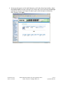
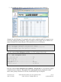
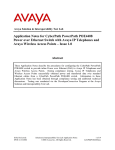
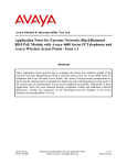
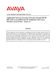
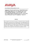
1
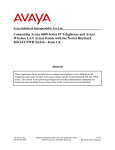
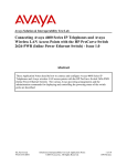
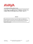
Avaya Solution & Interoperability Test Lab
Application Notes for CyberPath PowerPath POE4424
Power over Ethernet (PoE) Switch with Avaya IP
Telephones and Avaya Wireless Access Points – Issue 1.1
Abstract
These Application Notes describe the procedures for configuring the CyberPath PowerPath
POE4424 switch to provide inline Power over Ethernet (PoE) to Avaya IP Telephones and
Avaya Wireless Access Points. During compliance testing, Avaya IP Telephones and
Wireless Access Points successfully obtained power and transferred data over standard
Ethernet cables from a CyberPath PowerPath POE4424 switch. Information in these
Application Notes has been obtained through compliance testing and additional technical
discussions. Testing was conducted via the DeveloperConnection Program at the Avaya
Solution and Interoperability Test Lab.
SCR; Reviewed:
SPOC 9/15/2005
Solution & Interoperability Test Lab Application Notes
©2005 Avaya Inc. All Rights Reserved.
1 of 14
CyberPath-PoE.doc
1. Introduction
Power over Ethernet (PoE) allows both power and data to be simultaneously carried over
standard Ethernet cables. PoE-enabled Ethernet switches can supply power directly to Ethernet
devices, thereby simplifying installation and removing the need for separate power supplies for
those devices. The IEEE 802.3af standard defines the mechanisms for Power Sourcing
Equipment (PSE), such as PoE-enabled Ethernet switches, to detect, classify, and supply power
to Powered Devices (PDs), such as PoE-enabled IP telephones and wireless access points. In the
compliance-tested configuration described in these Application Notes, a CyberPath PowerPath
POE4424 switch is a PSE configured to supply inline PoE to Avaya PDs, specifically Avaya IP
Telephones and Avaya AP-8 Wireless Access Points.
As illustrated in Figure 1, the Avaya PDs covered in these Application Notes include the
following:
•
•
•
•
•
•
•
•
•
•
•
•
•
4601 IP Telephone
4602 IP Telephone and 4602SW IP Telephones
4610SW IP Telephone
4620 IP Telephone
4620SW IP Telephone
4621SW IP Telephone
4622SW IP Telephone
4625SW IP Telephone
4630SW IP Telephone
5601 IP Telephone
5602SW IP Telephone
Avaya Gen-2 4606, 4612, and 4624 IP Telephones
Avaya Wireless AP-8 802.11a/b/g Access Point
The Avaya 4612 and 4624 IP Telephones can be identified as Gen-2 by inspecting the model
number. “2A” in the model number indicates Gen-2. The model number can be found by:
• Inspecting the label attached to the bottom of the Telephone.
OR
• Pressing Mute, V, I, E, W, # on the keypad and then pressing * until the model number
appears. Press # to exit.
An example of a model number is 4612D02A-003 (Gen-2).
The Avaya 4620SW Class 2 and Class 3 IP Telephones can be differentiated by the microphone
at the bottom right side of the Telephone. If the microphone has one hole, it is Class 2, and if it
has two holes, it is Class 3.
SCR; Reviewed:
SPOC 9/15/2005
Solution & Interoperability Test Lab Application Notes
©2005 Avaya Inc. All Rights Reserved.
2 of 14
CyberPath-PoE.doc
The classifications of the phones are dependent on the Institute of Electrical and Electronics
Engineers (IEEE) 802.3af classifications for Powered Devices such as Avaya IP Telephones.
Each Powered Device is classified by the amount of power that it consumes into one of the
IEEE’s five classes. (The IEEE 802.3af PSE and Powered-Device Power Classifications chart
can be seen in Table 2).
The powering tests included verification of the following after the product was connected to the
switch:
• Successful boot operation.
• For Avaya IP Telephones, successful registration with Avaya Communication Manager
or Avaya IP Office (for the Avaya 5600-Series IP Telephones), completion of a test call,
and raising speakerphone volume to maximum value.
• For the Wireless LAN Access Point, successful registration of an Avaya IP Softphone
and an Avaya 3616 Wireless Telephone with Avaya Communication Manager and
completion of a test call.
• Connecting a mix of 22 Avaya IP Telephones and an Avaya AP-8 Wireless Access Point
to the switch, power cycling the switch and verifying successful boot operation and
registration of the devices to the Avaya Communication Manager.
Figure 1: PoE Interoperability Between CyberPath PowerPath POE4424 and Avaya IP
Telephones and Avaya Wireless Access Points
SCR; Reviewed:
SPOC 9/15/2005
Solution & Interoperability Test Lab Application Notes
©2005 Avaya Inc. All Rights Reserved.
3 of 14
CyberPath-PoE.doc
2. Equipment and Software Validated
The following equipment and software/firmware were used for the sample configuration
provided:
Equipment
Avaya S8300 Media Server in a G700 Media
Gateway
Avaya IP Office 412
Avaya 4601 IP Telephone
Avaya 4602 IP Telephone
Avaya 4602SW IP Telephone
Avaya 4610SW IP Telephone
Avaya 4620 IP Telephone
Avaya 4620SW IP Telephone
Avaya 4621SW IP Telephone
Avaya 4622SW IP Telephone
Avaya 4625SW IP Telephone
Avaya 4630SW IP Telephone
Avaya 5601 IP Telephone (IP Office specific)
Avaya 5602SW IP Telephone (IP Office specific)
Avaya Gen-2 4606 IP Telephone
Avaya Gen-2 4612 IP Telephone
Avaya Gen-2 4624 IP Telephone
Avaya AP-8 Wireless Access Point
Avaya IP Softphone
Avaya Voice Priority Processor
Avaya 3616 Wireless Telephone
CyberPath PowerPath POE4424
Software/Firmware
2.2/3.0
3.0(40)
1.8.0
1.8.2
1.8.2
2.1.3
2.1.3
2.1.3
2.2
2.2
2.5
2.0.2
1.810
1.806
1.8.2
1.8.2
1.8.2
2.6.0(914)
5.2.3.6
33/02
096.040
2.03.0.11PoE
3. Configure Inline Power over Ethernet on the POE4424
Inline Power over Ethernet (PoE) is supported on the POE4424. By default, PoE support is
enabled on all the POE4424 10/100 BaseT ports. Power over Ethernet can be configured on the
POE4424 via the browser interface or command line interface (CLI). To view and/or configure
PoE settings on the POE4424 via the browser interface:
SCR; Reviewed:
SPOC 9/15/2005
Solution & Interoperability Test Lab Application Notes
©2005 Avaya Inc. All Rights Reserved.
4 of 14
CyberPath-PoE.doc
1. Browse to the IP address configured for the POE4424 and log into the POE4424 using
the appropriate administrative privileges.
2. Click Administrator on the left hand pane to open the list of administrative functions
available on the POE4424.
SCR; Reviewed:
SPOC 9/15/2005
Solution & Interoperability Test Lab Application Notes
©2005 Avaya Inc. All Rights Reserved.
5 of 14
CyberPath-PoE.doc
3. To configure the POE4424’s PoE Usage Threshold and/or SNMP PoE Trap, click Switch
Settings on the left pane. In the Switch Settings page right pane, click the PoE tab.
4. The power usage for the POE4424, Usage Threshold % and Trap Mode, can be
configured in the page that gets displayed on the right pane.
SCR; Reviewed:
SPOC 9/15/2005
Solution & Interoperability Test Lab Application Notes
©2005 Avaya Inc. All Rights Reserved.
6 of 14
CyberPath-PoE.doc
5. Click PoE Port Controls in the left hand pane to configure PoE settings for a specific
port.
SCR; Reviewed:
SPOC 9/15/2005
Solution & Interoperability Test Lab Application Notes
©2005 Avaya Inc. All Rights Reserved.
7 of 14
CyberPath-PoE.doc
6. In the page that appears on the right hand pane, scroll to the desired port number. Select
the Power Priority to assign to the port (Low, High, and Critical) and enter the PD Type
(optional) for the port, for example, the phone type or other descriptive information.
Once finished, click Apply.
SCR; Reviewed:
SPOC 9/15/2005
Solution & Interoperability Test Lab Application Notes
©2005 Avaya Inc. All Rights Reserved.
8 of 14
CyberPath-PoE.doc
7. Click PoE Port Status to review the PoE status of all ports on the POE4424.
Alternatively, the following CLI commands can be used to explicitly enable PoE support on one
or all ports, configure the PoE priority of one or all ports, as well as allow users to attach a text
string to identify the location and type of PD connected to one or all PoE ports.
config inlinepower adminmode <slot.port/all> enable
config inlinepower priority <slot.port/all> <critical/high/low>
config inlinepower type <slot.port/all> <string>
Enter the command show inlinepower switch to view PoE settings for the switch.
(L2SW) >show inlinepower switch
Main PSE Power (W) .......................
Operation Status .........................
Power In Use (W) .........................
Usage Threshold (%) ......................
Trap Mode ................................
Software Version .........................
200
On
3
80
Disable
00.0400.00
Enter the command show inlinepower port summary <slot.port/all> to verify that PoE support
is enabled on one or all ports. The output of the command shown below displays the admin
mode, status, priority, detected 802.3af class, and defined PD type for all ports.
SCR; Reviewed:
SPOC 9/15/2005
Solution & Interoperability Test Lab Application Notes
©2005 Avaya Inc. All Rights Reserved.
9 of 14
CyberPath-PoE.doc
(L2SW) >show inlinepower port summary all
Port
---0.1
0.2
0.3
0.4
0.5
0.6
0.7
0.8
0.9
0.10
0.11
0.12
0.13
0.14
0.15
0.16
0.17
0.18
0.19
0.20
0.21
0.22
0.23
0.24
Admin
Mode
-----Enable
Enable
Enable
Enable
Enable
Enable
Enable
Enable
Enable
Enable
Enable
Enable
Enable
Enable
Enable
Enable
Enable
Enable
Enable
Enable
Enable
Enable
Enable
Enable
Detection
Status
----------Delivering
Delivering
Delivering
Searching
Searching
Searching
Searching
Searching
Searching
Searching
Searching
Searching
Searching
Searching
Searching
Searching
Searching
Searching
Searching
Searching
Searching
Searching
Searching
Searching
Power
Priority
-------Low
High
Critical
Low
Low
Low
Low
Low
Low
Low
Low
Low
Low
Low
Low
Low
Low
Low
Low
Low
Low
Low
Low
Low
Power
Class PD Type
----- ----------------------------------2
4602SW
2
4610SW
2
4620SW
0
0
0
0
0
0
0
0
0
0
0
0
0
0
0
0
0
0
0
0
0
For more detailed inline power information for one or all ports, enter the command show
inlinepower port detailed <slot.port/all>. The following screen shows a detailed listing of the
PoE settings for port 0.1.
(L2SW) >show inlinepower port detailed 0.1
Admin Mode ...............................
Detection Status .........................
Power Priority ...........................
Power Class ..............................
PD Type ..................................
MPS Absent Count .........................
Invalid Signature Count ..................
Power Denied Count .......................
Overload Count ...........................
Short Count ..............................
Power (mW) ...............................
Current (mA) .............................
SCR; Reviewed:
SPOC 9/15/2005
Enable
Delivering
Low
2
0
0
0
0
0
3300
69
Solution & Interoperability Test Lab Application Notes
©2005 Avaya Inc. All Rights Reserved.
10 of 14
CyberPath-PoE.doc
4. Interoperability Compliance Testing
The interoperability compliance testing focused on verifying PoE interoperability between the
CyberPath PowerPath POE4424 and Avaya IP Telephones and Avaya AP-8 Wireless Access
Point.
4.1. General Test Approach
The general test approach was to connect the Avaya PDs (Avaya IP Telephones and Avaya AP-8
Wireless Access Point) to PoE-enabled ports on the CyberPath PowerPath POE4424 and verify
that the PDs successfully boot. To verify that power and data can be simultaneously carried on
the PoE connections, phone calls were made from the IP Telephones to / from a 3616 Wireless
Telephone accessing the network via the AP-8 as well as to/from an IP Softphone on a wireless
laptop accessing the network via the AP-8.
4.2. Test Results
Most Power over Ethernet test cases completed successfully. The only issue encountered was
with the 5602SW IP Telephone as documented in Note 2 below. The CyberPath PowerPath
POE4424 successfully provided inline power to the Avaya PDs. Table 1 below lists the 802.3af
class, allocated power, and measured power of the Avaya PDs when connected to the CyberPath
PowerPath POE4424. The measured power listed is for the particular phone being tested. Cable
length and impedance affects power usage, so the measurements listed here may vary based on
the cable used.
Avaya Powered Device
Measured Power
Observations
(mW)
Idle
Spkr
max vol
4601
2
7
3100
See Note 1
4602
1
4
3100
3800
4602SW
2
7
3200
4000
4610SW
2
7
3200
3700
4620
3
15.4
7000
7300
4620SW (Post 11/2004)
2
7
5000
5400
4621SW
2
7
5100
4622SW
2
7
5100
5600
4625SW
3
15.4
7900
8400
4630SW
3
15.4
10700
11100
5601
2
7
3100
See Note 1
5602SW
1
4
3300
See Note 2
Gen-2 4606
0
15.4
5000
5100
Gen-2 4612
0
15.4
4800
5100
Gen-2 4624
0
15.4
4900
5100
AP-8
0
15.4
4200
See Note 3
Table 1: 802.3af Class, Allocated Power, and Measured Power for Avaya IP Telephones
and Wireless Access Point connected to CyberPath POE4424.
SCR; Reviewed:
SPOC 9/15/2005
802.3af
Class
Allocated
Power (W)
Solution & Interoperability Test Lab Application Notes
©2005 Avaya Inc. All Rights Reserved.
11 of 14
CyberPath-PoE.doc
Table 2 below summarizes the 802.3af classes.
Class
0
1
2
3
4
PSE Output Max. Power (W)
15.4
4.0
7.0
15.4
Treat as Class 0
Table 2: IEEE 802.3af PSE and Powered-Device Power Classifications
Note 1: The 4601 and 5601 IP Telephones do not have a speakerphone button.
Note 2: The 5602SW IP Telephone used in the lab registered as a Class 1 device but should
register as Class 2. Since the POE4424 rate caps its ports, when the Speaker volume is maxed on
the 5602SW, the POE4424 reports a FAULT on the port because the phone draws more power
than permitted for its class and resets the port. CyberPath does not currently provide a method
for overriding the port setting.
Note 3: Power drawn by AP-8 during the wireless IP Softphone call to an IP Phone is 4100 mW.
Power drawn during wireless IP Softphone call to 3616 Wireless Telephone is 5200 mW.
5. Verification Steps
The following steps may be used to verify the configuration:
1. Ensure that PoE has been enabled on the CyberPath POE4424 and the ports that serve the
PDs.
2. Connect the Avaya PD to a PoE enabled port on the CyberPath POE4424 and verify that
the PD powers on successfully. If the PD does not power on, enter the command show
inlinepower port summary <slot.port/all> to confirm PoE is enabled on the port.
3. Verify that the Avaya 4600 Series IP Telephones successfully register with Avaya
Communication Manager and complete phone calls to other phones (assumes the IP
telephones have been configured with the correct IP and call control information).
4. Verify that the Avaya 5600 Series IP Telephones successfully register with Avaya IP
Office and complete phone calls to other phones (assumes the IP telephones have been
configured with the correct IP and call control information).
5. Verify the Avaya Wireless Access Point by having an Avaya IP Softphone running on a
wireless laptop accessing the network via the Access Point successfully register with
Avaya Communication Manager and complete phone calls to other phones (assumes the
IP Softphone has been configured with the correct IP and call control information).
6. Verify the Avaya IP Telephone continues to function properly when the speakerphone
volume is turned up to max value.
SCR; Reviewed:
SPOC 9/15/2005
Solution & Interoperability Test Lab Application Notes
©2005 Avaya Inc. All Rights Reserved.
12 of 14
CyberPath-PoE.doc
7. Verify the POE4424 powers up a mix of 23 Avaya IP Telephones. Connect up to 23
Avaya IP Telephones to the POE4424. Connect the 24th port of the POE4424 to an
upstream switch. Connect the Avaya Communication Manager, DHCP Server and/or
Avaya IP Office to the upstream switch. Power cycle the POE4424 and verify all the
Avaya IP Telephones successfully power up and register to their corresponding switch.
6. Support
For technical support on CyberPath products, consult the support pages at
http://www.cyberpathinc.com or contact the CyberPath Customer Support Center at:
• Phone: 732-463-7700 ext. 221
• E-mail: [email protected]
7. Conclusion
These Application Notes describe the steps for configuring the CyberPath PowerPath POE4424
to provide inline Power over Ethernet (PoE) to the Avaya PDs, namely Avaya IP Telephones and
Avaya Wireless Access Points. During compliance testing, the Avaya PDs simultaneously
obtained power and transferred data over standard Ethernet cables from the CyberPath
PowerPath POE4424.
8. Additional References
•
Product documentation for Avaya products may be found at http://support.avaya.com.
•
Product documentation for CyberPath products may be found at:
http://www.cyberpathinc.com.
SCR; Reviewed:
SPOC 9/15/2005
Solution & Interoperability Test Lab Application Notes
©2005 Avaya Inc. All Rights Reserved.
13 of 14
CyberPath-PoE.doc
©2005 Avaya Inc. All Rights Reserved.
Avaya and the Avaya Logo are trademarks of Avaya Inc. All trademarks identified by ® and ™
are registered trademarks or trademarks, respectively, of Avaya Inc. All other trademarks are the
property of their respective owners. The information provided in these Application Notes is
subject to change without notice. The configurations, technical data, and recommendations
provided in these Application Notes are believed to be accurate and dependable, but are
presented without express or implied warranty. Users are responsible for their application of any
products specified in these Application Notes.
Please e-mail any questions or comments pertaining to these Application Notes along with the
full title name and filename, located in the lower right corner, directly to the Avaya
DeveloperConnection Program at [email protected].
SCR; Reviewed:
SPOC 9/15/2005
Solution & Interoperability Test Lab Application Notes
©2005 Avaya Inc. All Rights Reserved.
14 of 14
CyberPath-PoE.doc