1
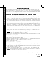
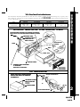
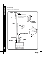
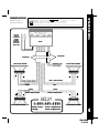
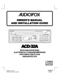
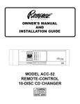
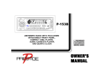
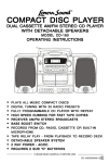
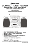
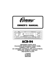
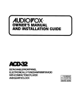
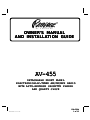
OWNER'S MANU
AL
MANUAL
AND INST
ALLA
TION GUIDE
INSTALLA
ALLATION
AV-455
DET
ACHABLE FRONT P
ANEL
DETACHABLE
PA
ELECTRONICALL
Y-TUNED AM/FM/MPX RADIO
ELECTRONICALLY
WITH A U T
O-REVERSE CASSETTE PLA
YER
TO-REVERSE
PLAY
AND QUARTZ CLOCK
Released 5-27-99.
128-5504
1 of 12
INSTALLATION INSTRUCTIONS
INSTALLATION INSTRUCTIONS
This unit is designed for installation in cars, trucks, and vans with an existing radio opening. In many cases, a
special installation kit will be required to mount the radio to the dashboard. These kits are available at electronics
supply stores and car stereo specialist shops. Always check the kit application before purchasing to make sure the
kit works with your vehicle. If you need a kit but cannot find it available, call our toll-free “HELP” line at
1-800-645-4994.
UNIVERSAL INSTALLATION PROCEDURE USING MOUNTING SLEEVE
1. Remove the detachable front panel if it is attached to the chassis by pushing the “Release” button. Slide the
mounting sleeve off of the chassis. If it is locked into position, use the removal tools (supplied) to disengage it.
2. Check the dashboard opening size by sliding the mounting sleeve into it. If the opening is not large enough, carefully
cut or file as necessary until the sleeve easily slides into the opening. Do not force the sleeve into the opening
or cause it to bend or bow. Check that there will be sufficient space behind the dashboard for the radio chassis.
3. Locate the series of bend tabs along the top, bottom, and sides of the mounting sleeve. With the sleeve fully inserted
into the dashboard opening, bend as many of the tabs outward as necessary so that the sleeve is firmly secured
to the dashboard.
4. Place the radio in front of the dashboard opening so that the wiring can be brought through the mounting sleeve.
Follow the wiring diagram carefully and make certain all connections of the wiring harness are secure and insulated
with wire nuts or electrical tape to insure proper operation of the unit. After completing the wiring connections, attach
the front panel and turn the unit on to confirm operation (ignition switch must be “on”). If unit does not operate,
re-check all wiring until problem is corrected. Once proper operation is achieved, turn off the ignition switch and
proceed with final mounting of the chassis.
5. Carefully slide the radio into the mounting sleeve making sure it is right-side-up until it is fully seated and the spring
clips lock it into place.
6. Attach one end of the perforated support strap (supplied) to the screw stud on the rear of the chassis using the
hex nut provided. Fasten the other end of the perforated strap to a secure part of the dashboard either above or
below the radio using the screw and hex nut provided. Bend the strap to position it as necessary.
CAUTION: The rear of the radio must be supported with the strap to prevent damage to the dashboard from the
weight of the radio or improper operation due to vibration.
7. Re-attach the front panel to the chassis and test radio operation by referring to the Operating Instructions for the unit.
INSTALLATION USING KITS
1. If your vehicle requires the use of an installation kit to mount this radio, follow the instructions included with the
installation kit to attach the radio to the mounting plate supplied with the kit.
2. Wire and test the radio as described in Step 4 above.
3. Install the radio/mounting plate assembly to the sub-dashboard according to the instructions of the installation kit.
4. Attach the support strap to the radio and dashboard as described in Step 6 above.
5. Replace the dashboard trim panel.
ISO INSTALLATION PROCEDURE
1
This unit has threaded holes in the chassis side panels which may be used with the original factory mounting brackets
of some Toyota, Nissan, Mitsubishi, Isuzu, Hyundai and Honda vehicles to mount the radio to the dashboard. Please
consult with your local car stereo specialist shop for assistance on this type of installation.
1. Remove the existing factory radio from its dashboard or center console mounting. Save all hardware and brackets
as they will be used to mount the new radio.
2. Carefully un-snap the plastic frame from the front of the new radio chassis. Remove and discard the frame.
3. Remove the factory mounting brackets and hardware from the existing radio and attach them to the new radio.
CAUTION: DO NOT EXCEED M5 X 8 MM MAXIMUM SCREW SIZE.
LONGER SCREWS MAY TOUCH AND DAMAGE COMPONENTS INSIDE THE CHASSIS.
4. Wire the new radio to the vehicle as per step 4 above.
5. Mount the new radio assembly to the dashboard or center console using the reverse procedure of step 1.
128-5504
2 of 12
UNIVERSAL INST
ALLA
TION USING MOUNTING SLEEVE
INSTALLA
ALLATION
EXISTING DASH OPENING (FILE EDGES TO FIT IF NECESSARY-DO NOT OVERFILE)
: IF DASH IS SOLID, USE MOUNTING SLEEVE AS A TEMPLATE & CUT OPENING
NOTE:
NOTE
NUT
PERFORATED STRAP
FASTEN THIS END TO
SCREW STUD ON
REAR OF CHASSIS
BEND TOP TABS
UPWARD
BEND BOTTOM TABS
DOWNWARD
SCREW
INSTALLATION INSTRUCTIONS
Toll-FreeInstallationAssistance
The installation and wiring connections for this unit are so simple, we doubt you'll need our help, but, if you do, we're
here to help you. Just call our toll-free telephone assistance line at 1-800-645-4994 during the days and hours shown
(U.S.A. and Canada only).
TIME ZONE
DAY
PACIFIC
MOUNTAIN
CENTRAL
EASTERN
MON.-FRI.
8:30AM - 7PM
5:30AM - 4PM
6:30AM - 5PM
7:30AM - 6PM
SATURDAY
9AM - 5PM
6AM - 2PM
7AM - 3PM
8AM - 4PM
RADIO
SCREW STUD
REMOVAL
TOOLS
MOUNTING SLEEVE
FASTEN THIS END TO SECURE PART
OF DASHBOARD.
DRILL HOLE IF NECESSARY.
DETACHABLE
FRONT PANEL
ISO INST
ALLA
TION
INSTALLA
ALLATION
REMOVE THE PLASTIC FRAME FROM THE
FRONT OF THE CHASSIS BY CAREFULLY
UN-SNAPPING IT.
TYPICAL INSTALLATION
MAX.SIZE
M5 x 8
UN-SNAP AT 2 PLACES
EACH ON TOP AND
BOTTOM
PLASTIC FRAME
MAX.SIZE
M5 x 8
FACTORY MOUNTING BRACKETS
2
128-5504
3 of 12
RADIO WIRING
RADIO WIRING
REFER TO PAGE 4 FOR SPEAKER WIRING
ANTENNA
AUTOMATIC
ANTENNA
BLUE
IMPORTANT
THE BLUE WIRE CAN BE USED TO
REMOTELY ACTIVATE AN AUTOMATIC ANTENNA OR AN EXTERNAL AMPLIFIER (SEE ANTENNA
OR AMPLIFIER MANUAL)
EXISTING
ANTENNA
CABLE
FUSEBLOCK
"RADIO" FUSE
+ 12V ACCESSORY
RED
SCREW
BLACK
METAL PART OF DASH
(DRILL HOLE IF NECESSARY)
CAR BATTERY
YELLOW
IMPORTANT
YELLOW WIRE MUST BE CONNECTED AS SHOWN
OR RADIO WILL NOT OPERATE PROPERLY
4 PIN PLUGS
POSITIVE (+) TERMINAL
12V BATTERY
9 PIN PLUG
(SEE PAGE 4 FOR SPEAKER WIRING)
ANTENNA LEAD ON
REAR OF RADIO
RADIO
3
128-5504
4 of 12
WARNING!
l
l
l
l
REFER TO PAGE 3
FOR RADIO WIRING
THE AMPLIFIERS IN THIS RADIO ARE O N L Y DESIGNED FOR USE WITH 4 SPEAKERS.
N E V E R COMBINE (BRIDGE) OUTPUTS FOR USE WITH 2 SPEAKERS.
N E V E R GROUND NEGATIVE SPEAKER LEADS TO CHASSIS GROUND.
FAILURE TO WIRE EXACTLY AS SHOWN BELOW MAY CAUSE ELECTRICAL DAMAGE TO THE RADIO.
RCA JACKS
LINE OUT
FOR USE WITH
OPTIONAL
EXTERNAL
AMPLIFIERS
RED = RIGHT
WHITE = LEFT
SPEAKER WIRING
SPEAKER WIRING
RADIO
4-PIN PLUGS
9-PIN PLUGS
LEFT FRONT SPEAKER
SEE PAGE 3 FOR
RADIO WIRING
RIGHT FRONT SPEAKER
GRAY w/BLACK STRIPE
WHITE w/BLACK STRIPE
GRAY
WHITE
GREEN
VIOLET
GREEN w/BLACK STRIPE
VIOLET w/BLACK STRIPE
HELP!
LEFT REAR SPEAKER
1-800-645-4994
Monday-Friday
Saturday
8:30am-7:00pmEastern
9:00am-5:00pmEastern
RIGHT REAR SPEAKER
4
128-5504
5 of 12
OPERATING INSTRUCTIONS
5
OPERATING INSTRUCTIONS
ON-OFF POWER BUTTON
Press this button to turn the unit on (“P ON” will
briefly appear on the display panel) or off.
VOLUME/LEVEL CONTROL
To increase the volume level, turn the knob clockwise.
The volume will increase and the level will be shown
on the display panel from a minimum of “VOL 00”to
a maximum of “VOL 63”. To decrease the volume
level, turn the knob counter-clockwise. The display
will automatically return to the normal indication 5
seconds after the last volume adjustment or when
another function is activated. This control is also
used in conjunction with the Select button
to
adjust the bass, treble, balance and fader levels as
described in
, , and
.
SELECT BUTTON
This button is used to select the audio function
(bass, treble, balance, or fade) to be adjusted using
the Level control
. Pressing the Select button
once will set the unit for volume adjustment (“VOL”
will appear on the display panel). Pressing the
button additional times will select bass adjustment
(“BAS” on the display), treble (“TRE”), balance
(“BA”), or fader (“FA”). The display will automatically
return to the normal indication 5 seconds after the
last adjustment or when another function is activated.
BASS CONTROL
To adjust the bass level, first select the Bass mode
so the “BAS”
by pressing the Select button
indication appears on the display panel. Within 5
seconds of choosing the Bass mode, turn the Level
control
counter-clockwise to decrease the bass
response or clockwise to increase it as desired. The
level will be shown on the display panel from a
minimum “BAS-06” to a maximum of “BAS+06”
(“BAS 00” indicates flat response). The display will
automatically return to the normal indication 5
seconds after the last adjustment or when another
function is activated.
TREBLE CONTROL
To adjust the treble level, first select the Treble mode
so the “TRE”
by pressing the Select button
indication appears on the display panel. Within 5
seconds of choosing the Treble mode, turn the Level
control
counter-clockwise to decrease the treble
response or clockwise to increase it as desired. The
level will be shown on the display panel from a
minimum “TRE -06” to a maximum of “TRE+06”
(“TRE 00”indicates flat response). The display will
automatically return to the normal indication 5
seconds after the last adjustment or when another
function is activated.
128-5504
6 of 12
AUDIO MUTE SELECTOR (MUTE)
Press this button momentarily to mute the volume
from the system (“MUTE” will flash on the display
panel). Pressing the button again or adjusting the
will return to the volume level
Volume control
setting in use before the Mute function was
activated.
AM/FM BAND SELECTOR (BAND)
RADIO MODE SELECTOR
Each time this button is pressed, the radio band is
changed. The indications “AMI”, “AMII”, “FMI”, “FMII”
or “FMIII” will appear in the display panel according to
your selection.
During cassette play, pressing this button will return
to radio operation.
MANUAL UP/DOWN TUNING (
/
)
AUTOMATIC SEEK TUNING (SEEK)
To manually select a radio station, momematrily
press the Up Tuning (
) side of the button to
advance the unit one digit higher or the Down Tuning
) side of the button to tune downward.
(
Pressing either side of the button for longer than 0.5
seconds will activate the Automatic Seek Tuning
function. The radio will seek the next station in the
selected direction and stop at that frequency. The
Seek function can be stopped by pressing the button
again or activating any other tuning function.
LOCAL/DISTANT SELECTOR (LO/DX)
This feature is used to select the strength of the
signals at which the radio will stop during Automatic
Seek Tuning. Pressing the button will select the Local
setting (“LOC” will appear on the display panel) and
only strong (local) stations will be received. Pressing
the button again will select the Distant setting (“LOC”
will disappear from the display panel) and the radio will
stop at a wider range of signals, including weaker
(more distant) stations.
FM MONO/STEREO SELECTOR (MONO)
During FM radio operation, this button is used to
select mono or stereo reception of the broadcast
signal. Under normal reception conditions, the unit
should be left in the stereo mode as indicated by the
“ST” on the display panel and the
symbol when
tuned to an FM stereo signal. If the stereo signal is
too noisy for comfortable listening, press the FM
Mono/Stereo Selector button to switch to mono
reception (the “ST” and
indications will disappear
OPERATING INSTRUCTIONS
LEFT/RIGHT BALANCE CONTROL
To adjust the left-right speaker balance, first select
the Balance mode by pressing the Select button
so the “BA” indication appears on the display panel.
Within 5 seconds of choosing the Balance mode,
turn the Level control
counter-clockwise to adjust
the stereo balance to the left channel speakers or
clockwise to adjust it to the right channel speakers.
The balance position will be shown on the display
panel from “BA L31” (full left) to “BA R31”(fullright).
When the volume level between the left and right
speakers is equal, “BA 00” will be shown on the
display panel. The display will automatically return
to the normal indication 5 seconds after the last
adjustment or when another function is activated.
FRONT/REAR FADER CONTROL
To adjust the front-rear speaker balance, first select
so
the Fader mode by pressing the Select button
the “FA” indication appears on the display panel.
Within 5 seconds of choosing the Fader mode, turn
the Level control
counter-clockwise to adjust the
front-rear speaker balance to the rear speakers or
clockwise to adjust it to the front speakers. The fader
position will be shown on the display panel from
“FA R 31” (full rear) to “FA F31” (full front). When the
level between the front and rear speakers is equal,
“FA 00” will be shown on the display panel. The
display will automatically return to the normal
indication 5 seconds after the last adjustment or
when another function is activated.
AUDIO EQUALIZER SELECTOR (EQ)
The Audio Equalizer feature adjusts the frequency
response, allowing you to tailor the sound
reproduction to 3 different acoustic settings. Each
press of the button will select a different effect
( R O C K , CLAS or P O P ) as shown by the
indication on the display panel. Pressing the button
again will restore normal stereo reproduction ( FLAT
indication on the display panel).
LOUDNESS CONTOUR (LOUD)
When listening to music at low volume levels, this
feature will boost the bass and treble ranges to
compensate for the characteristics of human hearing.
Press the button momentarily to activate this feature
and the indication “LOUD” will appear on the display
panel. Pressing the button again momentarily will
deactivate the feature (the “LOUD” indication will
disappear from the display panel).
6
128-5504
7 of 12
OPERATING INSTRUCTIONS
7
from the display panel). To return to stereo reception
mode, press the button again so that the “ST” indication
appears on the display panel.
PRE-SET SCAN (PS)
AUTO-STORE TUNING (AS)
Press this button momentarily to scan the stations
pre-set into the memories of the band in use. The unit
will stop at each pre-set station for 5 seconds before
continuing to the next pre-set station (the pre-set
number on the display panel will flash during Pre-Set
Scan operation). Press the button again momentarily
to stop Pre-Set Scan operation and remain on the
selected frequency.
Pressing and holding the button for longer than 2
seconds will activate the Auto-Store Tuning feature
(“ATP will appear on the display panel) which will
automatically scan and enter up to 6 stations into the
pre-set memories on the band in use. After entering
the stations into the memories, the unit will
automatically stop at each station for 5 seconds so
each can be heard. If you have already set the pre-set
memories to your favorite stations, activating the
Auto-Store Tuning feature will erase those stations
and enter the new ones. This feature is most useful
when travelling in a new area where you are not familiar
with the local stations.
STATION PRE-SET MEMORIES
To set any of the 6 pre-set memories in each band, use
the following procedure:
1. Turn the radio on and select the desired band.
2. Select the first station to be pre-set using the Manual
Up/Down or Automatic Seek Tuning Controls .
3. Press the pre-set button to be set and continue to
hold it in for approximately 2 seconds. The pre-set
number will appear on the display panel indicating
that the station is now set into that pre-set memory
position. The station can now be recalled at any
time by pressing that button.
4. Repeat the above procedure for the remaining 5 presets on that band and for the other 4 bands on the unit.
LIQUID CRYSTAL DISPLAY PANEL
The Liquid Crystal Display (LCD) panel displays the
frequency, time, and activated functions.
NOTE
:It is a characteristic of LCD panels that, if
NOTE:
subjected to cold temperatures for an extended
period of time, they may take longer to illuminate
than under normal conditions. In addition, the
visibility of the numbers on the LCD may slightly
decrease. The LCD read-out will return to normal
when the temperature increases to a normal range.
SPECTRUM ANALYZER DISPLAY
The Spectrum Analyzer Display feature incorporated
in this unit breaks down the audio frequency spectrum
into 5 bands and provides a visual indication of the
amount of audio signal within each of these bands.
The number of illuminated bars (1 to 10) shows the
instantaneous signal level in the band around the
indicated frequencies (105Hz., 340Hz., 1KHz.,
3.4KHz., and 10.5KHz.).
CASSETTE DOOR
To access the cassette door, press the Front Panel
so that the panel drops to its
Release button
lowered position. Hold the cassette with the exposed
tape edge to the right and insert it fully into the
cassette door until the cassette is engaged and
begins playing (“TAPE” will appear on the display
panel). When the cassette reaches the end on the
side of the tape being played, the unit will automatically
change direction of play as shown by the arrow
indications on the display panel.
NOTE
:Observe cassette operation cautions in Care
NOTE:
and Maintenance section of this manual.
&
FAST-FORWARD/REWIND BUTTONS
(
/
)
These buttons cause the tape to move rapidly in the
direction indicated by the arrows. For example, if the
button is pushed when the tape is moving from left
to right (
on the display panel), the tape will fastforward. If the button is pressed while the tape is
moving from right to left ( on the display panel), the
tape will rewind. To stop fast tape movement, lightly
push the opposite button. If the tape is allowed to fastforward or rewind all the way to the end, play will
automatically begin again from that point.
PROGRAM SELECTOR
To manually reverse tape direction and play the other
side (program) of the cassette, lightly push both the
Fast-Forward and Rewind buttons
and
at the
same time. The change of direction will be shown by
the arrows on the display panel.
EJECT BUTTON (
)
Tape playback is stopped and the cassette is ejected
by pressing this button located behind the front panel,
next to the tape door. Radio operation will automatically
128-5504
8 of 12
1. Uponinitialinstallationafterallwiringiscompleted.
2. If there is a malfunction of any of the switches on
the unit, pressing the Re-Set button may clear the
system and return to normal operation.
FRONT PANEL RELEASE BUTTON (OPEN)
This button is used to release the mechanism that
holds the front panel to the chassis. To detach the
front panel, press the button so that the panel drops to
the lowered position. Grasp the panel at the middle
and pull it off of the chassis. After removing the panel,
push the metal plate back up to the vertical position.
To re-attach the panel, press it straight onto the
chassis until the mechanism locks it into place.
NOTES ON USE OF FRONT PANEL
1. Make sure the front panel is right-side-up when
attaching it to the chassis as it cannot be attached
when up-side down.
2. Do not press very hard on the front panel when
attaching it to the chassis. No more than light to
moderate pressure should be needed.
3. When attaching the front panel, make sure it is
centered in the chassis frame and is pressed
straight into position.
4. When taking the front panel with you, please use
the supplied carrying case to protect the panel
from dirt and damage. Make sure there is no dust
or dirt on the electrical terminals on the back of
the panel as this could cause intermittent operation
or other malfunctions.
SETTING THE
OPERATING INSTRUCTIONS / SETTING THE CLOCK
resume when the cassette is ejected.
NOTE
:Never leave a cassette engaged in the player
NOTE:
when not in use. Doing so can cause damage
to the cassette and/or mechanism of the unit.
Always press the eject button and remove the
cassette before removing the detachable front panel.
TAPE MODE SELECTOR (TAPE)
During radio operation, press this button to change to
tape play if a cassette is already loaded in the unit
( TAPE IN is shown on the display panel to indicate
that a tape is loaded).
TIME/FREQUENCY SELECTOR (T/F)
Press this button to call the time display on the
incorporated quartz clock. The display will return to
the normal indication (radio frequency or “TAPE”) after
5 seconds.
THEFT-DETERRENT L.E.D.
Located on the chassis behind the front panel, a lightemitting diode (L.E.D.) will flash when the panel is
removed. The flashing light serves as a visual warning
to the would-be thief that the unit has been disabled by
removal of the front panel.
RE-SET BUTTON
A Re-Set button is located on the front of the chassis
(front panel must be removed to access the button).
The re-set circuitry is provided to protect the
microprocessor circuitry and should only be activated
under the following circumstances as it will erase the
time and pre-set memories.
CLOCK
on
1. Switch the vehicle ignition and radio "on
on"
.
2. Momentarily press the Time/Frequency Selector button
so that the time is shown on the display panel.
3. Within 5 seconds (while the time still appears on the display), press and hold the Time/Frequency Selector
and the Down Tuning (
) button to adjust the hours or the Up Tuning (
) button to adjust the minutes
to the correct time.
4. When the correct time is set, release the Time/Frequency Selector. After five seconds the display will
return to the normal indication.
8
128-5504
9 of 12
SPECIFICATIONS
SPECIFICATIONS//CARE
CAREAND
ANDMAINTENANCE
MAINTENANCE
SPECIFICATIONS
Size:
7" W
178 mm
x
x
2" H
50 mm
x
x
6" D
150 mm
Operating Voltage:
12 volts DC, negative ground
Output Power:
100 watts maximum (25 watts x 4 channels)
Output Wiring:
Floating-ground type designed for 4 speaker use.
The amplifiers in this unit are N O T designed for use with 2 speakers.
RCA pre-amp level outputs.
Output Impedance:
Compatible with 4 - 8 ohm speakers
Pre-Amp Output:
500 mv.
Tuning Range:
AM: 530 - 1,710 KHz. (10 KHz. step)
FM: 87.5 - 107.9 MHz. (200 KHz. step)
Sensitivity:
AM: 20 uv.
FM: 1.5 uv.
FM Stereo Separation:
30 dB
Tape Frequency Response: 50-10,000 Hz.
Tape S/N Ratio:
50 dB
Wow & Flutter:
0.15% WRMS
*Specifications are subject to change without notice.
CARE AND MAINTENANCE
The radio portion of your new sound system does not require any maintenance. We recommend you keep
this manual for future reference on how to set the clock and for general reference of the many features found
in this unit.
As with any cassette player, the cassette section of this sound system does require a minimum of
maintenance to keep it in good working condition. The following simple care and maintenance suggestions
should be followed to prevent malfunctions of the cassette system.
CassetteCare:
9
1. Purchase a cassette cleaning kit from your local retail store. Use it! At least every 20 to 30 hours
of operation you must clean the cassette mechanism. A dirty cassette player will have a poor sound.
2. Do not use cassettes that exceed 45 minutes of play on each side.
3. Do not insert a cassette that appears to be broken, twisted or dirty or with loose or torn labels on it.
4. Always keep your cassettes away from direct sunlight or exposure to sub-freezing conditions. If a
cassette is cold, allow it to warm up before use.
5. Do not keep a cassette in the player when not in use.
6. Before inserting a cassette in the player, check that the
tape is tightly wound on the reels. Take up any excess
slack using a pencil to turn the drive hub in the cassette
(see diagram).
128-5504
10 of 12
PROBLEM
PROBABLE CAUSE
CHECK FOLLOWING
Incorrect power connection
Red wire to +12V ACC. and Yellow wire to
+12V battery
Blown fuse
Check fuses in wires listed above and check
car fuse block
Incorrect power connection
Yellow wire is not connected to a "live" +12V
battery source
Blown fuse
Check fuse in Yellow wire and at car's fuse
block
Poor ground
Check Black wire for proper grounding
Dirty or corroded battery posts
Clean and tighten connection
Problem also existed with previous
radio you removed
Consult your local garage mechanic-car may
need tune-up or noise filter
Noise on radio only
Antenna
Check that antenna base is grounded. Test
with antenna disconnected. If noise goes
away, replace antenna
Poor FM reception and almost no AM
reception
Antenna
Replace antenna and antenna cable
Poor FM reception and good AM
reception
FM Local-Distant switch
Check if unit has a Local-Distant switch and
set to "Distant" position.
No sound on one speaker
(both radio and tape)
Wiring
Check speaker wiring
Speaker
Test with good speaker
Radio Operation
Check balance and fader controls
Poor sound on tape only (after one
month or more of tape usage)
Dirty tape mechanism
Clean tape head and mechanism
Poor sound - new unit
For radios with 40 watts or more
output power
Check rating of speakers for sufficient power
capacity
Unit completely inoperative no lights,
no sound
Unit will not keep time or radio station
memory
Noise on both radio and tape
TROUBLESHOOTING
TROUBLESHOOTING
Check that speakers are in good condition
Check that none of the speaker wires are
grounded
For all radios
Check speaker wiring
10
128-5504
11 of 12
12 MONTH LIMITED W
ARRANTY
WA
AUDIOVOX CORPORATION (the Company) warrants to the original retail purchaser of this product that
should this product or any part thereof, under normal use and conditions, be proven defective in material
or workmanship within 12 months from the date of original purchase, such defect(s) will be repaired
or replaced with new or reconditioned product (at the Company's option) without charge for parts and
repair labor.
To obtain repair or replacement within the terms of this Warranty, the product is to be delivered with
proof of warranty coverage (e.g. dated bill of sale), specification of defect(s), transportation prepaid,
to the warranty center at the address shown below.
This Warranty does not extend to the elimination of car static or motor noise, to correction of antenna
problems, to costs incurred for installation, removal, or reinstallation of the product, or damage to tapes,
compact discs, speakers, accessories, or vehicle electrical systems.
This Warranty does not apply to any product or part thereof which, in the opinion of the Company, has
suffered or been damaged through alteration, improper installation, mishandling, misuse, neglect,
accident, or by removal or defacement of the factory serial number/bar code label(s). THE EXTENT
OF THE COMPANY'S LIABILITY UNDER THIS WARRANTY IS LIMITED TO THE REPAIR OR
REPLACEMENT PROVIDED ABOVE AND, IN NO EVENT, SHALL THE COMPANY'S LIABILITY
EXCEED THE PURCHASE PRICE PAID BY PURCHASER FOR THE PRODUCT.
This Warranty is in lieu of all other express warranties or liabilities. ANY IMPLIED WARRANTIES,
INCLUDING ANY IMPLIED WARRANTY OF MERCHANTABILITY, SHALL BE LIMITED TO THE
DURATION OF THIS WRITTEN WARRANTY. ANY ACTION FOR BREACH OF ANY WARRANTY
HEREUNDER INCLUDING ANY IMPLIED WARRANTY OF MERCHANTABILITY MUST BE BROUGHT
WITHIN A PERIOD OF 30 MONTHS FROM DATE OF ORIGINAL PURCHASE. IN NO CASE SHALL
THE COMPANY BE LIABLE FOR ANY CONSEQUENTIAL OR INCIDENTAL DAMAGES FOR
BREACH OF THIS OR ANY OTHER WARRANTY, EXPRESS OR IMPLIED, WHATSOEVER. No
person or representative is authorized to assume for the Company any liability other than expressed
herein in connection with the sale of this product.
Some states do not allow limitations on how long an implied warranty lasts or the exclusion or limitation
of incidental or consequential damage so the above limitations or exclusions may not apply to you.
This Warranty gives you specific legal rights and you may also have other rights which vary from state
to state.
U.S.A. : AUDIOVOX CORPORATION, 150 MARCUS BLVD., HAUPPAUGE, NEW YORK 11788 l 1-800-645-4994
CANADA: CALL 1-800-645-4994 FOR LOCATION OF WARRANTY STATION SERVING YOUR AREA
128-4270E
© 1999 Audiovox Corporation
l
Hauppauge, NY 11788
Printed in China
128-5504
128-5504
12 of 12