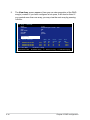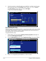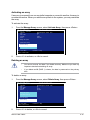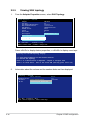
1
PIKE 1064E
LSISAS1064E RAID card
E3671
First Edition V1
March 2008
Copyright © 2008 ASUSTeK COMPUTER INC. All Rights Reserved.
No part of this manual, including the products and software described in it, may be reproduced,
transmitted, transcribed, stored in a retrieval system, or translated into any language in any form or by any
means, except documentation kept by the purchaser for backup purposes, without the express written
permission of ASUSTeK COMPUTER INC. (“ASUS”).
Product warranty or service will not be extended if: (1) the product is repaired, modified or altered, unless
such repair, modification of alteration is authorized in writing by ASUS; or (2) the serial number of the
product is defaced or missing.
ASUS PROVIDES THIS MANUAL “AS IS” WITHOUT WARRANTY OF ANY KIND, EITHER EXPRESS
OR IMPLIED, INCLUDING BUT NOT LIMITED TO THE IMPLIED WARRANTIES OR CONDITIONS OF
MERCHANTABILITY OR FITNESS FOR A PARTICULAR PURPOSE. IN NO EVENT SHALL ASUS, ITS
DIRECTORS, OFFICERS, EMPLOYEES OR AGENTS BE LIABLE FOR ANY INDIRECT, SPECIAL,
INCIDENTAL, OR CONSEQUENTIAL DAMAGES (INCLUDING DAMAGES FOR LOSS OF PROFITS,
LOSS OF BUSINESS, LOSS OF USE OR DATA, INTERRUPTION OF BUSINESS AND THE LIKE),
EVEN IF ASUS HAS BEEN ADVISED OF THE POSSIBILITY OF SUCH DAMAGES ARISING FROM ANY
DEFECT OR ERROR IN THIS MANUAL OR PRODUCT.
SPECIFICATIONS AND INFORMATION CONTAINED IN THIS MANUAL ARE FURNISHED FOR
INFORMATIONAL USE ONLY, AND ARE SUBJECT TO CHANGE AT ANY TIME WITHOUT NOTICE,
AND SHOULD NOT BE CONSTRUED AS A COMMITMENT BY ASUS. ASUS ASSUMES NO
RESPONSIBILITY OR LIABILITY FOR ANY ERRORS OR INACCURACIES THAT MAY APPEAR IN THIS
MANUAL, INCLUDING THE PRODUCTS AND SOFTWARE DESCRIBED IN IT.
Products and corporate names appearing in this manual may or may not be registered trademarks or
copyrights of their respective companies, and are used only for identification or explanation and to the
owners’ benefit, without intent to infringe.
ii
Contents
Contents....................................................................................................... iii
About this guide.......................................................................................... iv
PIKE 1064E specifications summary......................................................... vi
Chapter 1:
Product introduction
1.1
Welcome!....................................................................................... 1-2
1.3
Card layout.................................................................................... 1-3
1.2
1.4
1.5
Package contents.......................................................................... 1-2
System requirements.................................................................... 1-3
Card installation............................................................................ 1-4
Chapter 2:
2.1
2.2
2.1.1
2.1.2
RAID definitions............................................................... 2-2
Installing hard disk drives................................................. 2-2
LSI Corporation MPT Setup Utility.............................................. 2-3
2.2.1
Integrated Mirroring volume............................................. 2-3
2.2.3
Integrated Striping (IS) volume........................................ 2-9
2.2.2
2.2.4
2.2.5
2.2.6
Chapter 3:
3.1
RAID configuration
Setting up RAID............................................................................. 2-2
Integrated Mirroring Enhanced volume............................ 2-7
Managing Arrays.............................................................2-11
Viewing SAS topology.................................................... 2-16
Global Properties........................................................... 2-17
Driver installation
RAID driver installation................................................................ 3-2
3.1.1
Creating a RAID driver disk............................................. 3-2
3.1.3
Red Hat® Enterprise Linux OS......................................... 3-9
3.1.2
3.1.4
Windows® Server 2003 OS.............................................. 3-4
SUSE Linux Enterprise Server OS.................................3-11
iii
About this guide
This user guide contains the information you need when installing and configuring
the server management board.
How this guide is organized
This guide contains the following parts:
•
Chapter 1: Product introduction
This chapter offers the PIKE 1064E SAS RAID card features and the new
technologies it supports.
•
Chapter 2: RAID configuration
•
Chapter 3: Driver installation
This chapter provides instructions on setting up, creating, and configuring
RAID sets using the available utilities.
This chapter provides instructions for installing the RAID drivers on different
operating systems.
Where to find more information
Refer to the following sources for additional information and for product and
software updates.
1.
2.
iv
ASUS websites
The ASUS website provides updated information on ASUS hardware and
software products. Refer to the ASUS contact information.
Optional documentation
Your product package may include optional documentation, such as warranty
flyers, that may have been added by your dealer. These documents are not
part of the standard package.
Conventions used in this guide
To make sure that you perform certain tasks properly, take note of the following
symbols used throughout this manual.
DANGER/WARNING: Information to prevent injury to yourself
when trying to complete a task.
CAUTION: Information to prevent damage to the components
when trying to complete a task.
IMPORTANT: Instructions that you MUST follow to complete a
task.
NOTE: Tips and additional information to help you complete a
task.
Typography
Bold text
Indicates a menu or an item to select.
Italics
Used to emphasize a word or a phrase.
<Key> Keys enclosed in the less-than and greater-than sign means
that you must press the enclosed key.
Example: <Enter> means that you must press the Enter or
Return key.
<Key1+Key2+Key3>
If you must press two or more keys simultaneously, the key
names are linked with a plus sign (+).
Example: <Ctrl+Alt+D>
Command
Means that you must type the command exactly as shown,
then supply the required item or value enclosed in
brackets.
Example: At the DOS prompt, type the command line:
format a:
PIKE 1064E specifications summary
Controller
LSISAS1064E
Interface
ASUS PIKE interface
Ports
4 ports
Support device
SAS and SATA II devices
Data transfer rate
SATA II and SAS 3 Gb/s per PHY
RAID level
RAID0/RAID1/RAID1E
OS support*
Windows® Server 2003/2000/XP/Vista
Red Hat® Enterprise Linux 3/4/5
SUSE Linux Enterprise Server 8/9/10
LSI MegaRAID Storage Manager (MSM) for Windows®/
Linux operating systems
Form factor
6.44 in x 1.57 in (1U compatible)
* The exact OS support would base on the OS support list of the motherboard.
** Specifications are subject to change without notice.
vi
This chapter offers the PIKE 1064E SAS
RAID card features and the new technologies
it supports.
Chapter 1:
1
Product
introduction
1.1
Welcome!
Thank you for buying an ASUS® PIKE 1064E SAS RAID card!
The ASUS PIKE 1064E allows you to create RAID0, RAID1, and RAID1E set(s)
from SAS hard disk drives connected to the SAS connectors on the motherboard.
Before you start installing the RAID card, check the items in your package with the
list below.
1.2
Package contents
Check your package for the following items.
•
ASUS PIKE 1064E SAS RAID card
•
User guide
•
Support CD
If any of the above items is damaged or missing, contact your retailer.
1-2
Chapter 1: Product introduction
1.3
Card layout
The illustration below shows the major components of the RAID card.
3
2
2
1
1
1.
ASUS PIKE interface-1: PCI-E x8
3.
SAS RAID card status LED (lights up and blinks to indicate that the card is
working normally)
2.
ASUS PIKE interface-2: 4-port SAS signal with SGPIO interface*
* The SGPIO interface is used for visibility into drive activity, failure and reboot
status, so that users could build high-performatnce and reliable storage
systems. Refer to the motherboard manual for detailed information about
using the SGPIO connectors on the motherboard.
1.4
System requirements
Before you install the PIKE 1064E SAS RAID card, check if the system meets the
following requirements:
•
Workstation or server motherboard with a PIKE RAID card slot
•
Supporting operating system:
•
SAS or SATA hard disk drives
Windows® and Linux operating systems (refer to website for details)
•
Other requirement:
- Appropriate thermal solution
- Certified power supply module
ASUS PIKE 1064E
1-3
1.5
Card installation
Follow below instructions to install the RAID card on your motherboard.
1.
Locate the PIKE RAID card slot on
the motherboard.
2.
Align the golden fingers of the RAID
card with the PIKE RAID card slot.
3.
Insert the RAID card into the PIKE
RAID card slot. Make sure it’s
completely inserted into the PIKE
RAID card slot.
Connect the SAS hard disk
drives to SAS connectors 1-4
(red) on the motherboard when
using a 4-port PIKE RAID card.
The SAS connectors 5-8 (blue)
function when using a 8-port
PIKE RAID card.
1-4
Chapter 1: Product introduction
This chapter provides instructions on setting
up, creating, and configuring RAID sets using
the available utilities.
2
Chapter 2: RAID
configuration
2.1
Setting up RAID
The RAID card supports RAID 0, RAID 1 and RAID 1E set.
2.1.1
RAID definitions
RAID 0 (Data striping) optimizes two identical hard disk drives to read and write
data in parallel, interleaved stacks. Two hard disks perform the same work as a
single drive but at a sustained data transfer rate, double that of a single disk alone,
thus improving data access and storage. Use of two new identical hard disk drives
is required for this setup.
RAID 1 (Data mirroring) copies and maintains an identical image of data from one
drive to a second drive. If one drive fails, the disk array management software
directs all applications to the surviving drive as it contains a complete copy of
the data in the other drive. This RAID configuration provides data protection and
increases fault tolerance to the entire system. Use two new drives or use an
existing drive and a new drive for this setup. The new drive must be of the same
size or larger than the existing drive.
RAID 1E (Enhanced RAID 1) has a striped layout with each stripe unit having a
secondary (or alternate) copy stored on a different disk. You can use three or more
hard disk drives for this configuration.
If you want to boot the system from a hard disk drive included in a created RAID
set, copy first the RAID driver from the support CD to a floppy disk before you
install an operating system to the selected hard disk drive.
2.1.2
Installing hard disk drives
The RAID card supports SAS for RAID set configuration. For optimal performance,
install identical drives of the same model and capacity when creating a disk array.
To install the SAS hard disks for RAID configuration:
1.
2.
3.
2-2
Install the SAS hard disks into the drive bays following the instructions in the
system user guide.
Connect a SAS signal cable to the signal connector at the back of each drive
and to the SAS connector on the motherboard.
Connect a power cable to the power connector on each drive.
Chapter 2: RAID configuration
2.2
LSI Corporation MPT Setup Utility
The LSI Corporation MPT Setup Utility is an integrated RAID solution that allows
you to create the following RAID set(s) from SAS hard disk drives supported by the
LSI SAS 1064E controller:
•
RAID 1 (Integrated Mirroring)
•
RAID 0 (Integrated Striping)
•
RAID 1E (Integrated Mirroring Enhanced)
2.2.1
•
You may use disks of different sizes in IM and IME volumes; however, the
size of the smallest disk determines the “logical” size of each member disk.
•
DO NOT combine Serial ATA and SAS disk drives in one volume.
•
The RAID setup screens shown in this section are for reference only and
may not exactly match the items on your screen due to the controller
version difference.
Integrated Mirroring volume
The Integrated Mirroring (IM) feature supports simultaneous mirrored volumes with
two disks (IM).
The IM feature supports hot swap capability, so when a disk in an IM volume fails, you
can easily restore the volume, and the swapped disk is automatically re-mirrored.
To create an IM volume:
1.
2.
Turn on the system after installing all SAS hard disk drives.
During POST, press <Ctrl+C> to enter the SAS configuration utility.
LSI Corporation MPT SAS BIOS
MPTBIOS-6.20.00.00 (2007.12.04)
Copyright 2000-2007 LSI Corporation.
Press Ctrl-C to start LSI Corp Configuration Utility...
To avoid data loss, do not turn off the system when rebuilding.
ASUS PIKE 1064E
2-3
3.
The following screen appears. Select a channel and press <Enter> to enter
the setup.
LSI Corp Config Utility
v6.20.00.00 (2007.12.04)
Adapter List Global Properties
Adapter
PCI PCI PCI PCI FW Revision
Status
BUS Dev Fnc Slot
SAS1064E
02
00
00
20
1.24.00.00-IR
Enabled
Esc = Exit Menu F1/Shift+1 = Help
Alt+N = Global Properties -/+ = Alter Boot Order
Boot
Order
0
Ins/Del = Alter Boot List
The numbers of the channel depend on the controller.
4.
The Adapter Properties screen appears.
Use the arrow keys to select RAID Properties, then press <Enter>.
LSI Corp Config Utility
v6.20.00.00 (2007.12.04)
Adapter Properties -- SAS1064E
Adapter
SAS1064E
PCI Slot
20
PCI Address(Bus/Dev/Func)
02:00:00
MPT Firmware Revision
1.24.00.00-IR
SAS Address
500E0188:01111705
NVDATA Version
2D.02
Status
Enabled
Boot Order
0
Boot Support
[Enabled BIOS & OS]
RAID Properties
SAS Topology
Advanced Adapter Properties
Esc = Exit Menu
F1/Shift+1 = Help
Enter = Select Item -/+/Enter = Change Item
2-4
Chapter 2: RAID configuration
5.
The Select New Array Type screen appears.
Use the arrow keys to select Create IM Volume, then press <Enter>.
LSI Corp Config Utility
v6.20.00.00 (2007.12.04)
Select New Array Type -- SAS1064E
Create IM Volume
Create Integrated Mirror Array of 2
disks plus up to 2 optional hot spares.
Data on the primary disk may be migrated.
Create IME Volume
Create Integrated Mirrored Enhanced
Array of 3 to 10 disks including up
to 2 optional hot spares.
ALL DATA on array disks will be DELETED!
Create IS Volume
Create Integrated Striping array of
2 to 10 disks.
ALL DATA on array disks will be DELETED!
Esc = Exit Menu
F1/Shift+1 = Help
Enter = Choose array type to create
6.
The Create New Array screen shows the disks you can add to make up the IM
volume. Use the arrow key to select a disk, then move the cursor to the RAID
Disk column. To include this disk in the array, press <+>, <->, or <Space>.
You may also specify the Hot Spare disk here. Select the disk, then move the
cursor to the Hot Spr column, then press <+>, <->, or <Space>.
LSI Corp Config Utility
Create New Array -- SAS1064E
Array Type:
Array Size(MB):
Slot
Num
0
1
2
3
v6.20.00.00 (2007.12.04)
IM
------
Device Identifier
SEAGATE
SEAGATE
SEAGATE
SEAGATE
ST336754SS
ST336754SS
ST336754SS
ST336754SS
0003
0003
0003
0003
RAID
Disk
[No]
[No]
[No]
[No]
Hot
Spr
[No]
[No]
[No]
[No]
Esc = Exit Menu F1/Shift+1 = Help
SPACE/+/- = Select disk for array or hot spare
Drive
Status
-------------------------
Pred
Fail
-------------
Size
(MB)
35003
35003
35003
35003
C = Create array
By default, the RAID Disk field shows No before array creation. This field is
grayed out under the following conditions:
•
The disk does not meet the minimum requirements for use in a RAID array.
•
The disk is not large enough to mirror existing data on the primary drive.
•
The disk has been selected as the Hot Spare for the RAID array.
•
The disk is already part of another array.
ASUS PIKE 1064E
2-5
7.
A confirmation screen appears.
Press <M> to keep existing data on the first disk. If you choose this option,
data on the first disk will be mirrored on the second disk that you will add to
the volume later. Make sure the data you want to mirror is on the first disk.
Press <D> to overwrite any data and create the new IM array.
LSI Corp Config Utility
Create New Array -- SAS1064E
v6.20.00.00 (2007.12.04)
M - Keep existing data, migrate to an IM array.
Synchronization of disk will occur.
D - Overwrite existing data, create a new IM array.
ALL DATA on ALL disk in the array will be DELETED!!
No Synchronization performed.
Esc = Exit Menu
F1/Shift+1 = Help
Space/+/- = Select disk for array or hot spare
8.
9.
C = Create array
Repeat steps 5 and 6 to add the second disk to the volume.
When done, press <C> to create the array, then select Save changes then
exit this menu.
Create and save new array?
Cancel Exit
Save changes then exit this menu
Discard changes then exit this menu
Exit the Configuration Utility and Reboot
10. The utility creates the array.
LSI Corp Config Utility
v6.20.00.00 (2007.12.04)
Processing...may take up to 1 minute
Creating RAID array...
2-6
Chapter 2: RAID configuration
2.2.2
Integrated Mirroring Enhanced volume
The Integrated Mirroring Enhanced (IME) supports three to ten disks, or seven
mirrored disks plus two hot spare disks.
To create an IME volume:
1.
2.
Follow steps 1–4 of the section Integrated Mirroring volume.
The Select New Array Type screen appears.
Use the arrow keys to select Create IME Volume, then press <Enter>.
LSI Corp Config Utility
v6.20.00.00 (2007.12.04)
Select New Array Type -- SAS1064E
Create IM Volume
Create Integrated Mirror Array of 2
disks plus up to 2 optional hot spares.
Data on the primary disk may be migrated.
Create IME Volume
Create Integrated Mirrored Enhanced
Array of 3 to 10 disks including up
to 2 optional hot spares.
ALL Data on array disks will be deleted!
Create IS Volume
Create Integrated Striping array of
2 to 10 disks.
ALL Data on array disks will be deleted!
Esc = Exit Menu
F1/Shift+1 = Help
Enter = Choose array type to create
3.
The Create New Array screen shows the disks you can add to make up the
IME volume.
Integrated Mirroring Enhanced (IME) supports three to ten disks, or seven
mirrored disks plus two hot spare disks. Use the arrow key to select a disk,
then move the cursor to the RAID Disk column. To include this disk in the
array, press <+>, <->, or <Space>.
You may also specify the Hot Spare disk here. Select the disk, then move the
cursor to the Hot Spr column, then press <+>, <->, or <Space>.
LSI Corp Config Utility
Create New Array -- SAS1064E
Array Type:
Array Size(MB):
Slot
Num
0
1
2
3
v6.20.00.00 (2007.12.04)
IME
51498
Device Identifier
SEAGATE
SEAGATE
SEAGATE
SEAGATE
ST336754SS
ST336754SS
ST336754SS
ST336754SS
0003
0003
0003
0003
RAID
Disk
[Yes]
[No]
[Yes]
[Yes]
Hot
Spr
[No]
[No]
[No]
[No]
Esc = Exit Menu F1/Shift+1 = Help
SPACE/+/- = Select disk for array or hot spare
ASUS PIKE 1064E
Drive
Status
-------------------------
Pred
Fail
-------------
Size
(MB)
35003
35003
35003
35003
C = Create array
2-7
By default, the RAID Disk field shows No before array creation. This field is
grayed out under the following conditions:
4.
5.
•
The disk does not meet the minimum requirements for use in a RAID array.
•
The disk is not large enough to mirror existing data on the primary drive.
•
The disk has been selected as the Hot Spare for the RAID array.
•
The disk is already part of another array.
Repeat step 3 to add the other disks to the volume.
When done, press <C> to create the array, then select Save changes then
exit this menu.
Create and save new array?
Cancel Exit
Save changes then exit this menu
Discard changes then exit this menu
Exit the Configuration Utility and Reboot
6.
The utility creates the array.
LSI Corp Config Utility
v6.20.00.00 (2007.12.04)
Processing...may take up to 1 minute
Creating RAID array...
2-8
Chapter 2: RAID configuration
2.2.3
Integrated Striping (IS) volume
The Integrated Striping (IS) feature provides RAID 0 functionality, supporting
volumes with two to ten disks. You may combine an IS volume with an IM or IME
volume.
To create an IS volume:
1.
2.
Follow steps 1–4 of the section Integrated Mirroring volume.
The Select New Array Type screen appears.
Use the arrow keys to select Create IS Volume, then press <Enter>.
LSI Corp Config Utility
v6.20.00.00 (2007.12.04)
Select New Array Type -- SAS1064E
Create IM Volume
Create Integrated Mirror Array of 2
disks plus up to 2 optional hot spares.
Data on the primary disk may be migrated.
Create IME Volume
Create Integrated Mirrored Enhanced
Array of 3 to 10 disks including up
to 2 optional hot spares.
ALL DATA on array disks will be DELETED!
Create IS Volume
Create Integrated Striping array of
2 to 10 disks.
ALL DATA on array disks will be DELETED!
Esc = Exit Menu
F1/Shift+1 = Help
Enter = Choose array type to create
3.
The Create New Array screen shows the disks you can add to make up
the IS volume. Use the arrow key to select a disk, then move the cursor to
the RAID Disk column. To include this disk in the array, press <+>, <->, or
<Space>.
LSI Corp Config Utility
Create New Array -- SAS1064E
Array Type:
Array Size(MB):
Slot
Num
0
1
2
3
v6.20.00.00 (2007.12.04)
IS
102996
Device Identifier
SEAGATE
SEAGATE
SEAGATE
SEAGATE
ST336754SS
ST336754SS
ST336754SS
ST336754SS
0003
0003
0003
0003
RAID
Disk
[Yes]
[No]
[Yes]
[Yes]
Hot
Spr
[No]
[No]
[No]
[No]
Esc = Exit Menu F1/Shift+1 = Help
SPACE/+/- = Select disk for array or hot spare
ASUS PIKE 1064E
Drive
Status
-------------------------
Pred
Fail
-------------
Size
(MB)
35003
35003
35003
35003
C = Create array
2-9
By default, the RAID Disk field shows No before array creation. This field is
grayed out under the following conditions:
4.
5.
•
The disk does not meet the minimum requirements for use in a RAID array.
•
The disk is not large enough to mirror existing data on the primary drive.
•
The disk has been selected as the Hot Spare for the RAID array.
•
The disk is already part of another array.
Repeat step 3 to add the other disks to the volume.
When done, press <C> to create the array, then select Save changes then
exit this menu.
Create and save new array?
Cancel Exit
Save changes then exit this menu
Discard changes then exit this menu
Exit the Configuration Utility and Reboot
6.
The utility creates the array.
LSI Corp Config Utility
v6.20.00.00 (2007.12.04)
Processing...may take up to 1 minute
Creating RAID array...
2-10
Chapter 2: RAID configuration
2.2.4
Managing Arrays
The LSI Corporation MPT Setup Utility allows you to perform other tasks related to
configuring and maintaining IM and IME volumes.
Refer to this section to view volume properties, manage the hot spare disk,
synchronize the array, activate the array, and delete the array.
Viewing volume properties
To view volume properties:
1.
On the main menu, select RAID Properties.
LSI Corp Config Utility
v6.20.00.00 (2007.12.04)
Adapter Properties -- SAS1064E
Adapter
SAS1064E
PCI Slot
20
PCI Address(Bus/Dev/Func)
02:00:00
MPT Firmware Revision
1.24.00.00-IR
SAS Address
500E0188:01111705
NVDATA Version
2D.02
Status
Enabled
Boot Order
0
Boot Support
[Enabled BIOS & OS]
RAID Properties
SAS Topology
Advanced Adapter Properties
Esc = Exit Menu
F1/Shift+1 = Help
Enter = Select Item -/+/Enter = Change Item
2.
On the next screen that appears, select View Existing Array.
LSI Corp Config Utility
v6.20.00.00 (2007.12.04)
Select New Array Type -- SAS1064E
View Existing Array
View the existing configuration.
Create IM Volume
Create Integrated Mirror Array of 2
disks plus up to 2 optional hot spares.
Data on the primary disk may be migrated.
Create IME Volume
Create Integrated Mirrored Enhanced
Array of 3 to 10 disks including up
to 2 optional hot spares.
ALL DATA on array disks will be DELETED!
Create IS Volume
Create Integrated Striping array of
2 to 10 disks.
ALL DATA on array disks will be DELETED!
Esc = Exit Menu
F1/Shift+1 = Help
Enter = Choose array type to create
ASUS PIKE 1064E
2-11
3.
The View Array screen appears. Here you can view properties of the RAID
array(s) created. If you have configured a hot spare, it will also be listed. If
you created more than one array, you may view the next array by pressing
<Alt+N>.
LSI Corp Config Utility
View Array -- SAS1064E
Array
Identifier
Type
Scan Order
Size(MB)
Status
v6.20.00.00 (2007.12.04)
1 of 1
LSILOGICLogical Volume 3000
IME
0
51498
Optimal
Manage Array
Slot
Num
0
2
3
Device Identifier
SEAGATE ST336754SS
SEAGATE ST336754SS
SEAGATE ST336754SS
Esc = Exit Menu
Enter=Select Item
2-12
0003
0003
0003
RAID
Disk
Yes
Yes
Yes
Hot
Spr
No
No
No
Drive
Status
Ok
Ok
Ok
F1/Shift+1 = Help
Alt+N=Next Array C = Create an array
Pred
Fail
No
No
No
Size
(MB)
34331
34331
34331
R = Refresh Display
Chapter 2: RAID configuration
Managing hot spares
You may configure one disk as a global hot spare to protect critical data on the IM/IME
volume(s). You may create the hot spare disk at the same time you create the IM/IME
volume. Refer to this section when adding a hot spare disk on an existing volume.
If a disk on an IM/IME volume fails, the utility automatically rebuilds the failed
disk data on the hot spare. When the failed disk is replaced, the utility assigns
the replacement as the new hot spare.
To create a hot spare:
1.
2.
Follow steps 1–3 of the section Viewing volume properties.
From the View Array screen, select Manage Array, then press <Enter>.
LSI Corp Config Utility
View Array -- SAS1064E
Array
Identifier
Type
Scan Order
Size(MB)
Status
v6.20.00.00 (2007.12.04)
1 of 1
LSILOGICLogical Volume 3000
IME
0
51498
Optimal
Manage Array
Slot
Num
0
2
3
Device Identifier
SEAGATE ST336754SS
SEAGATE ST336754SS
SEAGATE ST336754SS
Esc = Exit Menu
Enter=Select Item
3.
0003
0003
0003
RAID
Disk
Yes
Yes
Yes
Hot
Spr
No
No
No
Drive
Status
Ok
Ok
Ok
Pred
Fail
No
No
No
Size
(MB)
34331
34331
34331
F1/Shift+1 = Help
Alt+N=Next Array C = Create an array
From the Manage Array screen, select Manage Hot Spares, then press
<Enter>.
LSI Corp Config Utility
Manage Array -- SAS1064E
Identifier
Type
Scan Order
Size(MB)
Status
v6.20.00.00 (2007.12.04)
LSILOGICLogical Volume 3000
IME
0
51498
Optimal
Manage Hot Spares
Synnchronize Array
Activate Array
Delete Array
Esc = Exit Menu
Enter = Select Item
ASUS PIKE 1064E
F1/Shift+1 = Help
2-13
4.
Use the arrow key to select the disk you would like to configure as hot spare,
then move the cursor to the Hot Spr column. Press <+>, <->, or <Space>.
The Drive Status column field now shows Hot Spare.
Press <C> to commit the changes.
LSI Corp Config Utility
Manage Hot Spare -- SAS1064E
Identifier
Type
Scan Order
Size(MB)
Status
Slot
Num
0
1
2
3
v6.20.00.00 (2007.12.04)
LSILOGICLogical Volume 3000
IME
0
51498
Optimal
Device Identifier
SEAGATE
SEAGATE
SEAGATE
SEAGATE
ST336754SS
ST336754SS
ST336754SS
ST336754SS
0003
0003
0003
0003
Hot
Spr
[No]
[No]
[No]
[Yes]
[----]
Drive
Status
Ok
Ok
Ok
Hot Spare
---------
Pred
Fail
No
No
No
No
--
Size
(MB)
34331
34331
34331
35003
-----
Esc = Exit Menu F1/Shift+1 = Help
SPACE/+/- = Change Item
C = Commit Changes
Synchronizing the array
Synchronizing the array allows the utility to resynchronize data on the mirrored disk
in the array. This procedure is seldom required because data synchronization is
automatically done during normal operation.
To synchronize the array:
1. Follow steps 1–3 of the section Viewing volume properties and step 2 of
the section Managing hot spares.
2.
From the Manage Array screen select Synchronize Array, then press <Enter>.
LSI Corp Config Utility
Manage Array -- SAS1064E
Identifier
Type
Scan Order
Size(MB)
Status
v6.20.00.00 (2007.12.04)
LSILOGICLogical Volume 3000
IME
0
51498
Optimal
Manage Hot Spare
Synnchronize Array
Activate Array
Delete Array
Esc = Exit Menu
Enter = Select Item
3.
2-14
F1/Shift+1 = Help
Press <Y> to begin the synchronization, or <N> to cancel.
Chapter 2: RAID configuration
Activating an array
If an array is removed from one controller/computer or moved to another, the array is
considered inactive. When you add the array back to the system, you may reactivate
the array.
To activate the array:
1.
From the Manage Array screen, select Activate Array, then press <Enter>.
LSI Corp Config Utility
Manage Array -- SAS1064E
Identifier
Type
Scan Order
Size(MB)
Status
v6.20.00.00 (2007.12.04)
LSILOGICLogical Volume 3000
IME
0
51498
Inactive
Manage Hot Spare
Synnchronize Array
Activate Array
Delete Array
Esc = Exit Menu
Enter = Select Item
2.
F1/Shift+1 = Help
Press <Y> to activate, or <N> to cancel.
Deleting an array
•
You cannot recover lost data if you delete an array. Make sure you back up
important data before deleting an array.
•
If you delete an IM (RAID 1) volume, the data is preserved on the primary
disk.
To delete an array:
1.
From the Manage Array screen, select Delete Array, then press <Enter>.
LSI Corp Config Utility
Manage Array -- SAS1064E
Identifier
Type
Scan Order
Size(MB)
Status
v6.20.00.00 (2007.12.04)
LSILOGICLogical Volume 3000
IM
0
34332
Optimal
Manage Hot Spare
Synnchronize Array
Activate Array
Delete Array
Esc = Exit Menu
Enter = Select Item
2.
F1/Shift+1 = Help
Press <Y> to delete, or <N> to cancel.
ASUS PIKE 1064E
2-15
2.2.5
1.
Viewing SAS topology
From the Adapter Properties screen, select SAS Topology.
LSI Corp Config Utility
v6.20.00.00 (2007.12.04)
Adapter Properties -- SAS1064E
Adapter
SAS1064E
PCI Slot
20
PCI Address(Bus/Dev/Func)
02:00:00
MPT Firmware Revision
1.24.00.00-IR
SAS Address
500E0188:01111705
NVDATA Version
2D.02
Status
Enabled
Boot Order
0
Boot Support
[Enabled BIOS & OS]
RAID Properties
SAS Topology
Advanced Adapter Properties
Esc = Exit Menu
F1/Shift+1 = Help
Enter = Select Item -/+/Enter = Change Item
Press <Alt+D> to display device properties, or <Alt+M> to display more keys.
More keys for the SAS Topology display:
C = Clear Device Mappings for Non-Present Devices
R = Refresh SAS Topology
Enter = On a SAS Enclosure or Expander - Expand or Collapse Item
Enter = On a Disk Drive - Turn on the Locate LED (next key press turns off)
2.
Information about the volume and its member-disks are then displayed.
LSI Corp Config Utility
v6.20.00.00 (2007.12.04)
SAS Topology -- SAS1064E
Device Identifier
Device
SAS1064E(02:00:00)
Info
﹂ Enclosure
Direct Attach Devices
Controller
﹂ IM VOL
LSILOGICLogical Volume 3000
Esc = Exit F1/Shift+1 = Help
Alt+D = Device Properties Alt+M = More Keys
2-16
Chapter 2: RAID configuration
2.2.6
Global Properties
From the Adapter List screen, press <Alt+N> to enter Global Properties menu.
From the menu you may change related settings.
LSI Corp Config Utility
v6.20.00.00 (2007.12.04)
Adapter List Global Properties
Adapter
PCI PCI PCI PCI FW Revision
Status
BUS Dev Fnc Slot
SAS1064E
02
00
00
20
1.24.00.00-IR
Enabled
Esc = Exit Menu F1/Shift+1 = Help
Alt+N = Global Properties -/+ = Alter Boot Order
Boot
Order
0
Ins/Del = Alter Boot List
Pause When Boot Alert Displayed
Sets whether to pause or not when the boot alert displays.
Configuration options: [Yes] [No]
LSI Corp Config Utility
Adapter List Global Properties
v6.20.00.00 (2007.12.04)
Pause When Boot Alert Displayed
Boot Information Display Mode
Support Interrupt
[No]
[Display adapters & installed devices]
[Hook interrupt, the Default]
Restore Defaults
Esc = Exit Menu
F1/Shift+1 = Help
Alt+N = Adapter List -/+ = Change Item
ASUS PIKE 1064E
2-17
Boot Information Display Mode
Sets the disk information display mode.
Configuration options: [Display adapters & installed devices]
[Display adapters only] [Display adapters and all devices]
[Display minimal information]
LSI Corp Config Utility
Adapter List Global Properties
v6.20.00.00 (2007.12.04)
Pause When Boot Alert Displayed
Boot Information Display Mode
Support Interrupt
[No]
[Display adapters & installed devices]
[Hook interrupt, the Default]
Restore Defaults
Esc = Exit Menu
F1/Shift+1 = Help
Alt+N = Adapter List -/+ = Change Item
Support Interrupt
Configuration options: [Hook interrupt, the Default] [Bypass interrupt hook]
LSI Corp Config Utility
Adapter List Global Properties
v6.20.00.00 (2007.12.04)
Pause When Boot Alert Displayed
Boot Information Display Mode
Support Interrupt
[No]
[Display adapters & installed devices]
[Hook interrupt, the Default]
Restore Defaults
Esc = Exit Menu
F1/Shift+1 = Help
Alt+N = Adapter List -/+ = Change Item
2-18
Chapter 2: RAID configuration
Restore Defaults
This option allows you to discard the selections you made and restore the system
defaults.
LSI Corp Config Utility
Adapter List Global Properties
v6.20.00.00 (2007.12.04)
Pause When Boot Alert Displayed
Boot Information Display Mode
Support Interrupt
[No]
[Display adapters & installed devices]
[Hook interrupt, the Default]
Restore Defaults
Esc = Exit Menu
F1/Shift+1 = Help
Alt+N = Adapter List -/+ = Change Item
ASUS PIKE 1064E
2-19
2-20
Chapter 2: RAID configuration
This chapter provides instructions for
installing the RAID drivers on different
operating systems.
Chapter 3:
3
Driver
installation
3.1
RAID driver installation
After creating the RAID sets for your server system, you are now ready to install
an operating system to the independent hard disk drive or bootable array. This part
provides instructions on how to install or update the RAID card drivers.
The RAID card driver might be included in the Linux OS installation CD, and
could be loaded automatically during OS installation. However, we recommend
using the RAID driver packaged in the RAID card support CD for better
reliability.
3.1.1
Creating a RAID driver disk
You may have to use another system to create the RAID driver disk from the
RAID card support CD or from the Internet.
A floppy disk with the RAID driver is required when installing Windows® Server 2003
or Linux operating system on a hard disk drive that is included in a RAID set. You
can create a RAID driver disk in DOS (using the Makedisk application in the support
CD).
To create a RAID driver disk in DOS environment:
1.
Place the RAID card support CD in the optical drive.
3.
Select the optical drive as the first boot priority to boot from the support CD.
Save your changes, then exit the BIOS Setup.
2.
4.
5.
Restart the computer, then enter the BIOS Setup.
Restart the computer.
Press any key when prompted to boot from CD.
Loading FreeDOS FAT KERNEL GO!
Press any key to boot from CDROM...
6.
The Makedisk menu appears. Select PIKE 1064E SAS Driver, and press
<Enter> to enter the sub-menu.
Create Driver Diskette Menu
PIKE 1064E SAS Driver
FreeDOS command prompt
3-2
Chapter 3: Driver installation
7.
Use the arrow keys to select the type of RAID driver disk you want to create.
PIKE 1064E SAS card Driver
Windows 2000 Server SP4
Windows XP 32 bit
Windows XP 64 bit
Windows Server 2003 32 bit
Windows Server 2003 64 bit
Windows Vista 32 bit
Windows Vista 64 bit
Windows Server 2008 32 bit
Windows Server 2008 64 bit
RHEL AS3 UP6/UP8/UP9 32 bit (Intel)
RHEL AS3 UP6/UP8/UP9 32 bit (AMD)
RHEL AS3 UP6/UP8/UP9 64 bit
RHEL AS4 UP4/UP5/UP6 32 bit
RHEL AS4 UP4/UP5/UP6 64 bit
SLES 9 32 bit
SLES 9 64 bit
SLES 9 SP1 32 bit
SLES 9 SP1 64 bit
SLES 9 SP2 32 bit
SLES 9 SP2 64 bit
SLES 9 SP3 32 bit
SLES 9 SP3 64 bit
8.
9.
Place a blank, high-density floppy disk to the floppy disk drive.
Press <Enter>.
10. Follow screen instructions to create the driver disk.
ASUS PIKE 1064E
3-3
3.1.2
Windows® Server 2003 OS
During Windows® Server 2003 OS installation
To install the RAID card driver when installing Windows® Server 2003 OS:
1.
2.
Boot the computer using the Windows® Server 2003 OS installation CD. The
Window® Setup starts.
Press <F6> when the message “Press F6 if you need to install a third party
SCSI or RAID driver...” appears at the bottom of the screen.
Windows Setup
Press F6 if you need to install a third party SCSI or RAID driver...
3.
The next screen appears. Press <S> to specify an additional device.
Windows Setup
Setup could not determine the type of one or more mass storage devices
installed in your system, or you have chosen to manually specify an adapter.
Currently, Setup will load support for the following mass storage devices(s):
<none>
* To specify additional SCSI adapters, CD-ROM drives, or special
disk controllers for use with Windows, including those for
which you have a device support disk from a mass storage device
manufacturer, press S.
* If you do not have any device support disks from a mass storage
device manufacturer, or do not want to specify additional
mass storage devices for use with Windows, press ENTER.
S=Specify Additional Device
3-4
ENTER=Continue
F3=Exit
Chapter 3: Driver installation
4.
Insert the RAID driver disk you created earlier to the floppy disk drive, then
press <Enter>.
Windows Setup
Please insert the disk labeled
Manufacturer-supplied hardware support disk
into Drive A:
* Press ENTER when ready.
ENTER=Continue
5.
ESC=Cancel
F3=Exit
Select LSI Fusion-MPT SAS Driver (Server 2003 32-bit), then press
<Enter>.
Windows Setup
You have chosen to configure a SCSI Adapter for use with Windows,
using a device support disk provided by an adapter manufacturer.
Select the SCSI Adapter you want from the following list, or press ESC
to return to the previous screen.
LSI Fusion-MPT SAS Driver (Server 2003 32-bit)
ENTER=Select
6.
7.
F3=Exit
The Windows® Setup loads the RAID card drivers from the RAID driver disk.
When next screen appears, press <Enter> to continue installation.
Setup then proceeds with the OS installation. Follow screen instructions to
continue.
ASUS PIKE 1064E
3-5
After Windows® Server 2003 OS installation
To update the RAID card driver after installing Windows® Server 2003 OS:
1.
2.
3.
4.
3-6
Right-click the My Computer icon on the desktop and select Properties from
the menu.
Click the Hardware tab on the top, then click the Device Manager button.
Double-click the LSI Adapter, SAS 3000 series, 4-port with 1064E -StorPort
item.
Click the Driver tab on the top, then click Update Driver.
Chapter 3: Driver installation
5.
Toggle Install from a list or specific location (Advanced), then click Next
to continue.
6.
Toggle Don’t search. I will choose the driver to install, then click Next to
continue.
7.
Insert the RAID driver disk you created earlier to the floppy disk drive.
8.
Highlight LSI Adapter, SAS 3000 series, 4-port with 1064E -StorPort, then
click Have Disk.
ASUS PIKE 1064E
3-7
9.
Select from the drop-down menu and locate the driver.
10. Click Next to start updating the driver.
11. After completing driver update, click Finish to close the wizard.
3-8
Chapter 3: Driver installation
3.1.3
Red Hat® Enterprise Linux OS
To install the RAID card driver when installing Red Hat® Enterprise OS:
1.
2.
Boot the system from the Red Hat® OS installation CD.
At the boot:, type linux dd, then press <Enter>.
- To install or upgrade in graphical mode, press the <ENTER> key.
- To install or upgrade in text mode, type: linux text <ENTER>.
- Use the function keys listed below for more information.
[F1-Main] [F2-Options] [F3-General] [F4-Kernel] [F5-Rescue]
boot: linux dd
3.
Select Yes using the <Tab> key when asked if you have the driver disk, then
press <Enter>.
Main Menu
Do you have a driver disk?
Yes
4.
No
Select fd0 using the <Tab> key when asked to select the driver disk source.
Press <Tab> to move the cursor to OK, then press <Enter>.
Driver Disk Source
You have multiple devices which could
serve as sources for a driver disk.
Which would you like to use?
fd0
scd0
OK
ASUS PIKE 1064E
Cancel
3-9
5.
Insert the Red Hat® Enterprise RAID driver disk to the floppy disk drive, select
OK, then press <Enter>.
Insert Driver Disk
Insert your driver disk into /dev/fd0
and press “OK” to continue.
OK
Back
The drivers for the RAID card are installed to the system.
6.
When asked if you will load additional RAID controller drivers, select No, then
press <Enter>.
More Driver Disks?
Do you wish to load any more
driver disks?
Yes
7.
3-10
No
Follow the screen instructions to continue the OS installation.
Chapter 3: Driver installation
3.1.4
SUSE Linux Enterprise Server OS
To install the RAID card driver when installing SUSE Linux Enterprise Server OS:
1.
2.
Boot the system from the SUSE OS installation CD.
Use the arrow keys to select Installation from the Boot Options menu.
Boot from Hard Disk
Installation
Installation--ACPI Disabled
Installation--Local APIC Disabled
Installation--Safe Settings
Rescue System
Memory Test
Boot Options |
F1 Help F2 Language F3 1280 x 1024 F4 DVD F5 Driver
3.
Press <F5>, then select Yes from the menu. Press <Enter>.
Boot from Hard Disk
Installation
Installation--ACPI Disabled
Installation--Local APIC Disabled
Installation--Safe Settings
Rescue System
Memory Test
Yes
No
File
F1 Help F2 Language F3 1280 x 1024 F4 DVD F5 Driver
Boot Options |
ASUS PIKE 1064E
3-11
4.
Insert the RAID driver disk to the floppy disk drive. Make sure that Installation
from the Boot Options menu is selected, then press <Enter>.
Boot from Hard Disk
Installation
Installation--ACPI Disabled
Installation--Local APIC Disabled
Installation--Safe Settings
Rescue System
Memory Test
Boot Options |
F1 Help F2 Language F3 1280 x 1024 F4 DVD F5 Driver
5.
When below screen appears, select the floppy disk drive (fd0) as the driver
update medium. Select OK, then press <Enter>.
Please choose the Driver Update medium.
fd0: Floppy
sr0: CD-ROM, TEAC DV-516E
sda: Disk, SEAGATE ST336754SS
sdb: Disk, SEAGATE ST336754SS
Other device
OK
3-12
Back
The drivers for the RAID controller are installed to the system.
Chapter 3: Driver installation