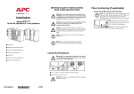
1
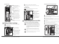
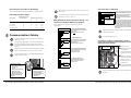
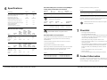
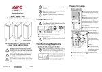
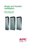
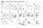
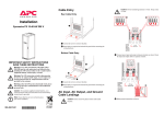
1 Cable Entry Preparing for top cable entry Rear Make sure that the UPS is in its location of use before you start the cabling. Note APC Smart-UPS® VT ISX Enclosure 20-30 kVA 480V for 5 Battery Modules and with Power Distribution Unit and Isolation Transformer IMPORTANT SAFETY INSTRUCTIONS SAVE THESE INSTRUCTIONS From the rear of the inside of the UPS push the top cover spring locks backwards to lift up the rear end of the top cover. Preparing for cabling (general) Slide out the top cover (mind the wing on either side of the plate). Punch holes in labeled area between the two rails on the rear of the Power module with cable landings for battery cables and communication cables Installation Cable entry takes place from the rear of the UPS. Pull out the lower end of the handle and turn it counterclockwise to a horizontal position to open the door. top cover for conduits as required. Line hole(s) with grommets (not supplied). Reinstall the top plate. Power Distribution Unit (PDU) Conduit box 2 AC and Ground Cable Landings Bottom cable entry Feed the input cables Cable landing area for AC input FAUL AULT ESC ? Use a torx screwdriver to loosen the four M4 screws from the cable landing cover and remove. Always read the separate Safety Sheet 990-2822 prior to the installation. Warning All electrical power and power control wiring must be installed by a qualified electrician, and must comply with local and national regulations for maximum power rating. The UPS must be supplied from a: 208Y/120V or 220Y/127V 4W+ GND 60 Hz source. L3 L1 L2 Use cable ties to Preparing for bottom and top entry Warning in conduits (not supplied) through the punched holes in the bottom plate. LOAD ON ON-BA ON-BATT TT BYPASS ASS Use a hammer to punch out knockouts and line holes with grommets (not supplied). attach the cables to the slotted plate. Connect the input cables (L1, L2, L3), to the cable landings. Connect the ground cable using the provided screw (earth symbol beneath the applicable screw). Reinstall bottom cable landing cover. Warning Power terminal lug diameter: minimum 6 mm. Torque value: 62 lbf.in/7 Nm. Note 990-2870B *990-2870B* 07/2006 Smart-UPS® VT ISX w/transformer and PDU, 20-30 kVA, 480 V, Installation Top cable entry Use cable ties to attach the cable to the slotted plate. Feed the input cables in Connect the battery cables Bat+ and Bat÷ and the N cable in the conduits (not supplied) through the punched holes. designated areas. Top cable entry Run the cables in the side panel. the punched holes in the bottom plate up to the cable landing. Use cable ties to attach the cables to the slotted plate. Connect the input cables (L1, L2 L3 Connect the ground cable Reinstall bottom cable landing 3 L2, L3), to the cable landings. using the provided screw (earth symbol beneath applicable screw). L1 cover. Battery Cable Landings The UPS may ONLY be connected to the APC SUVTBXR Battery Enclosure. 4 Note remove top cable landing covers. Feed the battery cable through the bottom of the UPS. On the outside of the bottom cover, run the cable in conduits (not provided) to the conduit box. Feed the cables through the conduit box. Smart-UPS® VT ISX w/transformer and PDU, 20-30 kVA, 480 V, Installation Feed the battery cables through the punched holes in the top cover. Connect the battery cables Bat+ and Bat÷ and the N cable in the designated areas. Preparing to connect the load to the PDU(s) Use a torx screwdriver to Use a torx screwdriver to remove the top cable landing covers. Connecting Load to the PDU Bottom cable entry Set the top PDU breaker to the OFF position. Using a torx screwdriver, remove the four M4 screws from the top plate of PDU. Remove plate. Connect the L1, L2, L3, N to the terminals and tighten the M6 screws firmly. Fasten cables with cable ties. Note See how to punch holes in the top cover in section 1: Preparing for top cable entry. Guide the input cables through Connecting load to the 4-pole breaker Note Connect the load equipment evenly between the 3 phases to avoid overloading the PDU. The total output capacity of the PDU is approximately twice the output capability of the UPS. This means that UPS would be over-loaded if all PDU outlets were loaded to their rating. Load status on the individual phases can be found through the UPS display or through the web interface. Equipment connected to the 3-phased output may require overcurrent protection with a lower rating than the 3-phased output. Attach the ground cable to the ground stud (labeled earth) and fasten with cable tie. Use a torx screwdriver to reinstall the top plate removed in step 2. Feed the cable through the hole in the top cover. Connecting load to the 3-pole breaker(s) Set the applicable breaker to the OFF position. Insert the plug from the load into the receptacle. Secure the plug by turning it clockwise approximately 30°. Set the applicable breaker to the ON position to supply the load. For 3-phased output, the highest current may be in the Neutral conductor at non-linear loads (up to 173%). Note Smart-UPS® VT ISX w/transformer and PDU, 20-30 kVA, 480 V, Installation Disconnecting the load from the PDU(s) The UPS must be connected to either a dry contact or a 24 VDC EPO switch. To disconnect the load, set the applicable breaker to the OFF position. Note PDU output breaker ratings Rear of unit 5 Ambient temperature in front of unit ºC 20 50 63 Free exhaust 20 17 42.5 53.55 Free exhaust 30 16 40.0 50.40 Free exhaust 40 15 37.5 47.25 Hot aisle exhaust 25 16 40.0 50.40 Communication Cables Emergency Power Off (EPO) switch must be connected to a NEC Class 2 circuit. Note Note EPO (Emergency Power Off) switch wiring – pin connections J108 (for EPO wiring options) Use only 28-16 AWG copper wire for the connection of the EPO switch and other optional equipment. Keep all other wiring and uninsulated live parts separate of other NEC Class 2 circuits. Do not connect any circuits to the EPO terminal block unless it can be confirmed that the circuit is a NEC Class 2 circuit. Note Note 1 2 3 4 5 6 EPO circuit 1 EPO circuit 3 4 EPO is activated when an isolated SELV 24VDC voltage is supplied on pin 1 with reference to pin 2. Prewired connection 3-5 and 4-6 6 4 3 3 2 2 1 1 Pins 7 and 8 are for external charge control. When 7 and 8 are closed, the UPS charges batteries with a pre-defined percentage (0-2550-75-100%) of the maximum charging power. To be used in generator applications, or if special codes requires control of charging. When Q3 is closed, signals are fed back to the UPS controller. J200 (XR Batteries) When connecting the Q3 auxiliary signal, use gold-plated N/C auxiliary switch on Q3. Note Note Connection of APC communication options – PowerChute software and temperature sensor (identical cable routing) 3: Dry Contacts Normally Closed 1 EPO is activated when a connection from pin 3 to pin 5 is opened. Prewired connection 4-6. 2 4 ! Output Pwr Temp. sensor Power Chute Zone Probe 10/100Base-T Reset 10/100 AP9619 Network Management Card EM EPO circuit ! Output Pwr Zone Probe 10/100Base-T Reset 10/100 AP9619 Network Management Card 5 6 4 Open front door. Temperature sensor/ PowerChute software J108 3 * Should be used with APC XR Enclosures 4 5 4: +24V Normally Closed EPO is activated when a SELV 24VDC voltage removed from pin 3 with reference to pin 4. 2 Ext. charging control return External control of charging Q3 active return Q3 active Battery measurement supply* Battery unit quantity* Max. battery temperature* Battery measurement return* EPO is activated when pin 1 is connected to pins 3 and 5. Prewired connection 2-4-6, 3-5 and 1 => 2: +24V Normally Open J108 1 8 7 6 5 4 3 2 1 Q3 switch 5 Pins 5 and 6 are for external maintenance bypass Q3 (auxiliary switch N/C type). When Q3 is closed, signals are fed back to the UPS controller. Reinstall cable landing covers. J108 J106 Pin Connections: 6 1: Dry Contracts Normally Open J108 3 Remove top cable landing covers as described under Battery Cable Landings, top entry. Charging control switch 7 Connect the EPO cable, using one of the following 4 wiring configurations: 2 Note Pins 1 to 4 are for battery measurement (only applicable to APC XR Battery Enclosures). J106 8 Always follow the pin connection procedures from the top and work down: J106 (8-1), J108 (1-6). Nominal rating of breaker Pin connections J106 (UPS) Serial: Model: BATTERY UNIT Serial: Model: BATTERY UNIT Serial: Model: BATTERY UNIT Serial: Model: BATTERY UNIT EPO circuit Serial: Model: BATTERY UNIT Serial: Model: BATTERY UNIT Serial: Model: BATTERY UNIT Feed cables from optional communication equipment through the opening in the top cover. EM Guide the cables along the inside of the left side panel down to the opening in the power module frame. Serial: Model: BATTERY UNIT Connect communication 5 6 Serial: Model: BATTERY UNIT Serial: Model: BATTERY UNIT Serial: Model: BATTERY UNIT Serial: Model: BATTERY UNIT equipment where shown. J108 Pin Connections: 1 2 3 4 5 6 Normally open EPO Normally open EPO return Normally closed EPO Normally closed EPO return +24V SELV supply SELV ground Smart-UPS® VT ISX w/transformer and PDU, 20-30 kVA, 480 V, Installation The APC communication options are provided at the front of the UPS. Note Smart-UPS® VT ISX w/transformer and PDU, 20-30 kVA, 480 V, Installation 6 Specifications Recommended phase-conductor sizes [AWG] for a 86°F (30°C) temperature environment UPS ratings UPS/AWG sizes AC input [AWG] AC output [AWG] DC input [AWG], 75ºC Wire 20 kVA 30 kVA Input voltage / Bypass voltage (V) per phase 480 480 20 kVA 6 4 4 Input current (nominal) (A) 25.5 36.8 30 kVA 4 1 1 Input frequency (Hz) range 60 60 Output voltage (on line) (Vac) Minimum and maximum values(± 1%) 3x208/120 3x208/120 Output current (nominal, per phase) (A) 55.5 83.3 Maximum output current (in bypass only at 110% overload per phase) 61.1 91.6 Cable Size [AWG] Cable Lug Type Neutral output current (with 100% switch mode load) (A) 37.5 56.7 6 If fuses are preferred, the following can be used: Note Die Terminal Bolt Diameter YA6CL2TC38 MD7-34R W5CVT 0.2 in/6 mm 4 YA4CL2TC38 MD7-34R W4CVT 0.2 in/6 mm 1 YA1CL2TC38 MD7-34R W1CVT 0.2 in/6 mm At 100% non-linear load (EN50091-3 standard), the neutral shall be rated for 173% phase current. 20kVA Internal fault 800% overload bypass operation 125% overload normal/ battery operation Continuously Mains input 4 kA – – – 68 A Bypass input 2.3 kA 444 A – – 62 A Duration <10 ms 500 ms 30 s 60 s ∞ Notes 1 Warning 150% overload normal/ battery operation 125% overload normal/ battery operation Continuously 30kVA Internal fault Mains input 5 kA – – – 102 A Bypass input 4.2 kA 444 A – – 92 A Duration <10 ms 500 ms 30 s 60 s ∞ Notes 1 Note 1: the short-circuit level is indicated for the output value. Smart-UPS® VT ISX w/transformer and PDU, 20-30 kVA, 480 V, Installation 40 A 30 kVA version 480 V input voltage 50 A Breakers/fuses other than APC SUVTOPT need complete selectivity assessments. 7 Checklist • Do not apply electricity to the UPS. • Do not connect batteries in the UPS. Recommended current protection • If an XR Battery Enclosure is installed make sure that the DC breaker (if available) is in the OFF position and that both 125A fuses are removed from the XR Battery Enclosure. To ensure the correct functionality of the PDU and to avoid unintentional tripping of the bypass input protection device follow the following recommendation: • Check that the power wiring is torqued to 62 lbf.in/7 Nm. • Verify clockwise phase-rotation (L1, L2, L3) and make sure a neutral connection is present. Use the SUVTOPT114 (20 kVA version) or the SUVT115 (30 kVA version) as input protection. 800% overload bypass operation 20 kVA version 480 V input voltage Note Minimum breaker settings 150% overload normal/ battery operation Breaker/fuse Ensure that the short-circuit current on the UPS input is less than 14 kAiC sym RMS. Also take into consideration the below breaker settings to ensure correct functionality during overload operation. Use Molex lug type or equivalent, and crimp to manufacturer’s specifications. Crimping Tool UPS size • If the installation includes an XR Battery Enclosure, remount the 125A fuses in the XR Battery Enclosure and check that the DC breaker (if available) on the XR Battery Enclosure is in the ON position. Output protection is included in the PDU of the unit. Note: Using a solution solely based on breakers, selectivity for load short circuit currents higher than 2 kA cannot be assured for the 3-phased output. If this is required, use fuses to protect the bypass. • Leave a wiring diagram on site for service personnel. • Close the rear door. UPS size Fuse type 20 kVA version 480 V input voltage 40 A Class J time delay fuse 30 kVA version 480 V input voltage 50 A Class J time delay fuse • For any optional equipment, refer to product-specific manuals. 8 Contact Information If a problem occurs, phone Customer Support at (1) (800) 800-4272 (US and Canada). For country-specific centers: go to www.apc.com/support/ contact. Web Support: write to [email protected] Smart-UPS® VT ISX w/transformer and PDU, 20-30 kVA, 480 V, Installation