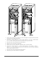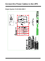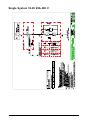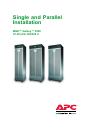
1
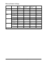
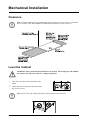
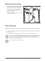
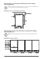
Single and Parallel
Installation
MGE™ Galaxy™ 3500
10-30 kVA 208/220 V
American Power Conversion Legal Disclaimer
The information presented in this manual is not warranted by the American Power Conversion
Corporation to be authoriative, error free, or complete. This publication is not meant to be
a substitute for detailed operational and site specific development plan. Therefore, American
Power Conversion Corporation assumes no liability for damages, violations of codes, improper
installation, system failures, or any other problems that could arise based on the use of this
Publication.
The information contained in this Publication is provided as is and has been prepared solely
for the purpose of evaluating data center design and construction. This Publication has been
compiled in good faith by American Power Conversion Corporation. However, no presentation
is made or warranty, either express or implied, as to the completeness or accuracy of the
information this Publication contains.
NO EVENT SHALL AMERICAN POWER CONVERSION CORPORATION BE LIABLE
FOR ANY DIRECT, INDIRECT, CONSEQUENTIAL, PUNITIVE, SPECIAL, OR
INCIDENTAL DAMAGES (INCLUDING, WITHOUT LIMITATION, DAMAGES FOR
LOSS OF BUSINESS, CONTRACT, REVENUE, DATA, INFORMATION, OR BUSINESS
INTERRUPTION) RESULTING FROM, ARISING OUT, OR IN CONNECTION WITH THE
USE OF, OR INABILITY TO USE THIS PUBLICATION OR THE CONTENT, EVEN IF
AMERICAN POWER CONVERSION CORPORATION HAS BEEN EXPRESSLY ADVISED
OF THE POSSIBILITY OF SUCH DAMAGES. AMERICAN POWER CONVERSION
CORPORATION RESERVES THE RIGHT TO MAKE CHANGES OR UPDATES WITH
RESPECT TO OR IN THE CONTENT OF THE PUBLICATION OR THE FORMAT
THEREOF AT ANY TIME WITHOUT NOTICE.
Copyright, intellectual, and all other proprietary rights in the content (including but not limited
to software, audio, video, text, and photographs) rests with American Power Conversion
Corporation or its licensors. All rights in the content not expressly granted herein are reserved.
No rights of any kind are licensed or assigned or shall otherwise pass to persons accessing
this information.
This Publication shall not be for resale in whole or in part.
Table of Contents
IMPORTANT SAFETY INSTRUCTIONS – SAVE THESE
INSTRUCTIONS ............................................................................................................... 1
Specifications ................................................................................................................... 2
AC Input Specifications.............................................................................................. 2
AC Bypass Input Specifications .............................................................................. 2
AC Output Specifications .......................................................................................... 3
Battery Specifications ................................................................................................ 3
Recommended Cable Sizes ...................................................................................... 4
Connection Terminals ................................................................................................ 4
Torque Specifications ................................................................................................ 4
Fuses and Breakers ....................................................................................................
Single Utility/Mains System .......................................................................................
Dual Utility/Mains System ..........................................................................................
Parallel System ..........................................................................................................
Fuse and Breaker Sizes in Single Systems ................................................................
Fuse and Breaker Sizes in Parallel Systems ..............................................................
Minimum Breaker Settings ........................................................................................
5
5
5
6
6
6
7
Mechanical Installation ............................................................................................... 8
Clearance ....................................................................................................................... 8
Level the Cabinet ......................................................................................................... 8
Remove the Front Panel ............................................................................................ 9
Floor Anchoring .......................................................................................................... 9
Hole Positions for a Stand-alone UPS Enclosure with L-shaped Anchoring
Brackets ....................................................................................................................10
Hole Positions for Up to Four UPS Units in Parallel with U-shaped Anchoring
Brackets ...................................................................................................................10
Connect Floor Anchoring Brackets to the UPS and XR Battery Enclosure for
Stability......................................................................................................................11
Remove the Battery Modules .....................................................................................12
Install the Baying Kit (Optional) for Interconnection of Enclosures and Seismic
Anchoring ..................................................................................................................13
Install XR Battery Enclosures (Option) ..............................................................16
Remove the Cable Landing Cover and Bottom Plates ......................................16
Connect Battery Power in Installations with Busbars .......................................17
Isolator Installation Principle .....................................................................................17
990-1957C-001 MGE™ Galaxy™ 3500 10-30 kVA 208/220 V Single and Parallel Installation
i
Install Busbars in 523 mm (20.59 in) UPS System with the UPS Placed to the Left
(seen from the front) ..................................................................................................18
Install Busbars in 523 mm (20.59 in) UPS System with the UPS Placed to the
Right (seen from the front) ........................................................................................19
Install Busbars in 352 mm (13.85 in) UPS System with the UPS Placed to the
Right (seen from the front) ........................................................................................20
Install Busbars in 352 mm (13.85 in) UPS System with the UPS Placed to the Left
(seen from the front) ..................................................................................................21
Connect Battery Power in Installations with Cables ..........................................22
Connect Power Cables Between the UPS and the XR Battery Enclosure ..................22
Connect Power Cables between Two XR Battery Enclosures ....................................23
Connect the Power Cables to the UPS ...............................................................25
Single System 10-30 kVA 208 V................................................................................25
Single System 10-30 kVA 480 V................................................................................26
Prepare for Cables .......................................................................................................27
Bottom Cable Entry ...................................................................................................27
Connect the AC Input and AC Output Cables ......................................................28
Single Mains ..............................................................................................................28
Dual Mains .................................................................................................................28
Connect the DC Battery Cables (if applicable) ...........................................................29
Connect the Communication Cables ..................................................................30
Prepare for Communication Cables........................................................................30
Overview of Pin Connections ...................................................................................31
J106 ...........................................................................................................................31
EPO in Single Systems...............................................................................................32
EPO in Parallel Systems ............................................................................................33
Connect Communication Cables between UPS and XR Battery
Enclosure .......................................................................................................................34
Connect APC Communication Options .................................................................35
Connect Communication Cables in Parallel System..........................................36
Overview of the PBus Cables ....................................................................................36
Prepare for Cables .....................................................................................................37
UPS Units Apart without Conduits and Interconnection ..................................38
UPS Units Bayed Together without Conduits ......................................................39
UPS Units Apart or Bayed Together with Conduits ...........................................40
Install Seismic Option ..................................................................................................42
Install the Seismic Battery Lock ..............................................................................42
ii
MGE™ Galaxy™ 3500 10-30 kVA 208/220 V Single and Parallel Installation 990-1957C-001
Install the Seismic Stabilizing Brackets ................................................................42
Final Mechanical Installation ...................................................................................44
Connect Battery Securing Brackets for Stability ................................................44
Reinstall the Top Cover and the Front Panel .......................................................45
990-1957C-001 MGE™ Galaxy™ 3500 10-30 kVA 208/220 V Single and Parallel Installation
iii
iv
MGE™ Galaxy™ 3500 10-30 kVA 208/220 V Single and Parallel Installation 990-1957C-001
IMPORTANT SAFETY INSTRUCTIONS –
SAVE THESE INSTRUCTIONS
WARNING: ALL safety instructions in the Safety Sheet (990-2940) must be read,
understood, and followed when installing the UPS system. Failure to do so could result
in equipment damage, serious injury, or death.
WARNING: After the UPS has been electrically wired, do not start it up. Start-up is
commissioned to authorized personnel from Schneider Electric.
WARNING: When the UPS input is connected through external isolators that, when
opened, isolate the neutral, or is connected to an IT power distribution system, a label
must be fitted at the UPS input terminals by the UPS supplier, and on all primary
power isolators installed remote from the UPS area and on external access points
between such isolators and the UPS by the user, displaying the following text (or
equivalent): "Risk of voltage backfeed. Before working on this circuit, isolate the UPS
and check for hazardous voltage between all terminals including the protective earth."
Caution: All electrical power and power control wiring must be installed by a qualified
electrician and must comply with local and national regulations for maximum power rating.
Caution: Wait until the system is ready be powered up before installing batteries. Failure
to do so can result in a deep discharge of the batteries and cause permanent damage (the
time from the battery installation time till the UPS is powered up should not exceed 72
hours or 3 days.
Note: The system is designed for connection to an IT power distribution system.
Note: The parallel cables must be run by the electrician but not attached. The field service
engineer from Schneider Electric will install the parallel communication box and attach all
cables to the UPS units.
Note: Up to four UPS units can run in parallel.
Note: Ensure that the all UPS units are in their final location prior to the installation.
Note: Battery and utility/mains power must not be connected until all other wiring has
been completed.
990-1957C-001
MGE™ Galaxy™ 3500 10-30 kVA 208/220 V Single and Parallel Installation
1
Specifications
WARNING: The UPS must be supplied from a 208/120 V or 220/127 V 4W + GND
60 HZ source.
AC Input Specifications
10 kVA
208 V
15 kVA
220 V
20 kVA
30 kVA
208 V
220 V
208 V
220 V
208 V
220 V
Connection type
4-wire (3PH + N + G)
Input frequency
(Hz)
40-70
I thd
< 5% at full load
Nom input current
(A)
24.3
23.0
36.6
34.6
48.6
45.8
73.2
69.0
Max input current
(A)
26.7
25.2
40.2
38.0
53.0
50.1
80.1
75.8
Input current
limitation (A)
32.8
32.8
49.5
49.5
65.2
65.2
98.8
98.8
Input power factor
correction
> 0.98 at load > 50%
Maximum Short
Circuit Withstand
(kA)
30
AC Bypass Input Specifications
10 kVA
208 V
15 kVA
220 V
Connection type
4-wire (3PH + N + G)
Input frequency
(Hz)
50 +/- 10 or 60 +/- 10
Nom input current
(A)
27.8
2
26.2
20 kVA
30 kVA
208 V
220 V
208 V
220 V
208 V
220 V
41.6
39.4
55.5
52.5
83.3
78.7
MGE™ Galaxy™ 3500 10-30 kVA 208/220 V Single and Parallel Installation
990-1957C-001
AC Output Specifications
10 kVA
208 V
15 kVA
220 V
208 V
20 kVA
220 V
Connection type
4-wire (3PH + N + G)
Overload capacity
150% for 1 minute (normal operation)
125% for 10 minutes (normal operation)
150% for 1 minute (battery operation)
125% for 10 minutes (battery operation)
110% continuous (bypass operation)
800% for 500 ms (bypass operation)
Voltage tolerance
160-240 V for 208 V systems
160-253 V for 220 V systems
Nom output
current (A)
27.8
Output frequency
(sync to mains)
50 Hz ±0.1 Hz, ±3 Hz, ±10 Hz
60 Hz ±0.1 Hz, ±3 Hz, ±10 Hz
Slew rate (Hz/Sec)
0.25-1
Total Harmonic
Distortion (THD)
< 1.5% linear
< 3.5% non-linear
Load power factor
0.5 leading to 0.5 lagging
Dynamic load
response
± 5%
Output voltage
regulation
± 1%
26.2
41.6
39.4
30 kVA
208 V
220 V
208 V
220 V
55.5
52.5
83.3
78.7
Battery Specifications
Type
VRLA
Nominal voltage (VDC)
+/- 192
Float voltage (VDC)
+/- 219
End of discharge voltage (VDC)
+/- 154
Battery current (at full load)
66.5 A at +/-192 V
Max. current (at end of discharge)
83.2 A at + 154 V
Max. charging power
10 kVA: 1600 W
15 kVA: 2400 W
20 kVA: 3200 W
30 kVA: 3200 W
Typical re-charge time
5 hours
End voltage
1.6-1.75 V/cell (automatic, depending on load)
990-1957C-001
MGE™ Galaxy™ 3500 10-30 kVA 208/220 V Single and Parallel Installation
3
Recommended Cable Sizes
WARNING: At 100% switch mode load, the neutral must be rated for 200% phase
current.
Caution: All wiring must comply with all applicable national and/or electrical code.
Note: The recommended cable sizes are based on an environment with an ambient
temperature of 30° C (86° F). Use stranded copper cables.
10 kVA
15 kVA
20 kVA
30 kVA
Utility/mains input
8 AWG
6 AWG
4 AWG
1 AWG
Static bypass input
8 AWG
6 AWG
4 AWG
1 AWG
DC input
1 AWG
1 AWG
1 AWG
1 AWG
Output
8 AWG
6 AWG
4 AWG
1 AWG
Connection Terminals
Cable size (AWG)
Cable lug type
Crimping tool
Die
Terminal bolt
diameter
12
YA12CL2TC38
MD7-34R
W12CVT
6 mm (0.2 in)
8
YA8CL2TC38
MD7-34R
W8CVT
6 mm (0.2 in)
6
YA6CL2TC38
MD7-34R
W6CVT
6 mm (0.2 in)
4
YA4CL2TC38
MD7-34R
W4CVT
6 mm (0.2 in)
1
YA1CL2TC38
MD7-34R
W1CVT
6 mm (0.2 in)
Torque Specifications
The power wiring should be torqued to 7 Nm (45 lbf-in).
4
MGE™ Galaxy™ 3500 10-30 kVA 208/220 V Single and Parallel Installation
990-1957C-001
Fuses and Breakers
Single Utility/Mains System
• Q1: Utility/mains input
• Q2: UPS output
• Q3: Manual bypass
• MBS: Mechanical bypass switch
Dual Utility/Mains System
• Q1: Utility/mains input
• Q2: UPS output
• Q3: Manual bypass
• Q5: Static bypass input
• MBS: Mechanical bypass switch
990-1957C-001
MGE™ Galaxy™ 3500 10-30 kVA 208/220 V Single and Parallel Installation
5
Parallel System
• Q1: Utility/mains input
• Q2: UPS output
• Q3: Manual bypass
• Q4: System output
• Q5: Static bypass input
Fuse and Breaker Sizes in Single Systems
10 kVA
15 kVA
20 kVA
30 kVA
Utility input Q1
35 A
60 A
80 A
110 A
Static bypass input
Q5
35 A
60 A
80 A
110 A
UPS output Q2
35 A
60 A
80 A
110 A
Manual bypass Q3
35 A
60 A
80 A
110 A
Fuse and Breaker Sizes in Parallel Systems
Q3 and Q4 in Parallel Capacity Systems
Units in parallel
10 kVA
15 kVA
20 kVA
30 kVA
2
70 A
110 A
150 A
225 A
3
110 A
175 A
225 A
350 A
4
150 A
225 A
300 A
450 A
Q3 and Q4 in Redundant Parallel Systems (n+1)
Units in parallel
10 kVA
15 kVA
20 kVA
30 kVA
2
35 A
60 A
80 A
110 A
3
70 A
110 A
150 A
225 A
4
110 A
175 A
225 A
350 A
6
MGE™ Galaxy™ 3500 10-30 kVA 208/220 V Single and Parallel Installation
990-1957C-001
Minimum Breaker Settings
10 kVA
15 kVA
20 kVA
30 kVA
1
800% overload
bypass
operation
150% overload
normal/battery
operation
125% overload
normal/battery
operation
Continuously
Duration
500 ms
60 s
10 min
Mains input
-1
-
-
34 A
Static bypass
input
223 A
-
-
31 A
UPS output
223 A
42 A
35 A
31 A
Mains input
-1
-
-
51 A
Static bypass
input
333 A
-
-
46 A
UPS output
333 A
63 A
52 A
46 A
Mains input
-1
-
-
68 A
Static bypass
input
444 A
-
-
62 A
UPS output
444 A
84 A
70 A
62 A
Mains input
-1
-
-
99 A
Static bypass
input
667 A
-
-
92 A
UPS output
667 A
125 A
105 A
92 A
For single mains systems, use the higher value of mains and static bypass
990-1957C-001
MGE™ Galaxy™ 3500 10-30 kVA 208/220 V Single and Parallel Installation
7
Mechanical Installation
Clearance
Note: Clearance dimensions are published for airflow and service access only. Consult with
the local safety codes and standards for additional requirements in your local area.
Level the Cabinet
WARNING: The system must be installed on a level floor. The leveling feet will stabilize
the cabinet, but will not account for a badly sloped floor.
1. Take the 13/14 mm wrench attached to the
pallet.
2. Adjust the four leveling feet and ensure that
the system is level.
Note: Do not move the cabinet after the leveling feet have been lowered.
8
MGE™ Galaxy™ 3500 10-30 kVA 208/220 V Single and Parallel Installation
990-1957C-001
Remove the Front Panel
1. Use a coin or similar to turn the two black lock
devices on either side of the display in the
direction of each other to a vertical position.
2. Push the front panel upwards and pull it
outwards to disengage the locking device at
the top of the enclosure.
3. Lift the front panel free of the two slots at the
bottom of the enclosure.
Floor Anchoring
There are two floor anchoring options that can be used depending on the requirements in the installation
area:
• For stability: Reuse the L-shaped brackets that secured the enclosure to the pallet during shipment
for a stand-alone UPS.
• For seismic anchoring: Use a baying kit that includes U-shaped seismic anchoring brackets.
Note: Allow for enough working space behind the enclosure for electrical work to be carried
out (e.g. if you want to install an XR Battery Enclosure at a later stage). Minimum rear
clearance is 100 mm (3.93 in) and must comply with applicable national and local codes.
600 mm (23.6 in) is recommended.
Note: Hole positions are guidelines only.
990-1957C-001
MGE™ Galaxy™ 3500 10-30 kVA 208/220 V Single and Parallel Installation
9
Hole Positions for a Stand-alone UPS Enclosure with L-shaped
Anchoring Brackets
Note: Recommended minimum number of screws per enclosure for the L-shaped brackets is
four; one in each corner. Recommended floor bolt size: M8.
Model Width: 352 mm (13.85 in) and 523 mm (20.59 in)
Hole Positions for Up to Four UPS Units in Parallel with U-shaped
Anchoring Brackets
Note: Recommended minimum number of floor screws for the two configurations below
is 10.
Model Width: 352 mm (13.85 in)
10
MGE™ Galaxy™ 3500 10-30 kVA 208/220 V Single and Parallel Installation
990-1957C-001
Model Width: 523 mm (20.59 in)
Connect Floor Anchoring Brackets to the UPS and XR Battery
Enclosure for Stability
Note: Floor anchoring bolts are not provided with the UPS. Purchase the bolts locally
(minimum size: M8). Follow the specifications given by the manufacturer of the floor
anchoring system when bolting the UPS system to the floor.
1. Install the L-shaped floor anchoring brackets
(reuse the two transport brackets) and secure
with the M6 screws and nuts (provided).
2. Drill two to six holes in the floor for each
bracket and attach these with bolts.
990-1957C-001
MGE™ Galaxy™ 3500 10-30 kVA 208/220 V Single and Parallel Installation
11
Remove the Battery Modules
Note: Two people are needed to lift the battery modules.
Note: The XR Battery Enclosures ship with two battery modules. All battery modules in
the UPS and the XR Battery Enclosure(s) must be removed before interconnecting these
enclosures.
Note: When you remove battery modules, start from the highest row and work your way
down.
2
3
1
1. Remove all battery securing brackets (used to secure the batteries during transport) by removing
the M6 Torx screws.
2. Remove the blind plate.
3. To release the battery from its lock mechanism, gently push the battery upwards and then pull it
out while supporting the battery with your other hand.
12
MGE™ Galaxy™ 3500 10-30 kVA 208/220 V Single and Parallel Installation
990-1957C-001
Install the Baying Kit (Optional) for Interconnection of Enclosures and
Seismic Anchoring
Caution: Baying kits are required in seismic areas.
1. Remove the side panels from the enclosure(s) to get access to the holes in the bottom frame.
UPS
UPS
Note: Make sure that the enclosures are level so that they can be anchored to each other.
2. Position two U-shaped floor anchoring brackets under one enclosure; one on each side.
2
2
Note: The U-shaped anchoring brackets are 1-2 mm higher than the opening below the
enclosure to inactivate the casters. Therefore, the enclosure must be tilted when placing the
U-shaped anchoring brackets under the enclosure.
990-1957C-001
MGE™ Galaxy™ 3500 10-30 kVA 208/220 V Single and Parallel Installation
13
3. On each side of the same enclosure insert a maximum of nine and a minimum of two M8 screws
(not provided) through holes in the bottom of the enclosure and through holes in the U-shaped
floor anchoring brackets, and into the pre-drilled floor holes.
3
4. Fasten the screws.
4
5. Move the adjacent enclosure on its casters close to the enclosure with the U-shaped floor
anchoring brackets.
Note: If the adjacent enclosure is on its leveling feet, use a forklift or pallet jack to move it
into position to avoid damaging the leveling feet.
14
MGE™ Galaxy™ 3500 10-30 kVA 208/220 V Single and Parallel Installation
990-1957C-001
6. Insert the interconnection plates between the two enclosures. One is positioned toward the front
and the other toward the rear. Notice how the “wings” on the interconnection plates rest in slots at
the top of the inner panel.
UPS
UPS
6
7
7
7
7
7
7
10
5
8
7. Align the two enclosures and level the three marked rows of bolt holes in UPS 1 with the holes
in UPS 2.
8. Push the two enclosures firmly together.
9. Bolt the two enclosures together using the six M6x25 mm screws and nuts supplied in the kit; join
one hole at the front and one hole at the rear of the enclosures on three levels.
10. Position the third U-shaped floor anchoring bracket under the adjacent enclosure (see previous
graphics) and insert a minimum of two floor anchoring M8 screws (not provided) through the
holes in the bottom of the enclosure and through the holes in the U-shaped floor anchoring bracket,
and into the predrilled floor holes, and then fasten the screws.
990-1957C-001
MGE™ Galaxy™ 3500 10-30 kVA 208/220 V Single and Parallel Installation
15
Install XR Battery Enclosures (Option)
Remove the Cable Landing Cover and Bottom Plates
WARNING: Before carrying out the steps below, the system must be in total power
off and the batteries must be removed.
To access the cable landing area in the UPS and the XR Battery Enclosure(s), follow this procedure:
XR Battery Enclosure
UPS
1
1
4
4
3
3
2
2
1. Loosen the six M4 screws from the cable landing cover plate on the UPS and the XR Battery
Enclosure(s) and then remove the plates.
2. In installations with busbar connections, remove the screws from the bottom plate on the UPS
and the XR Battery Enclosure(s) and then remove the plates.
3. Punch holes in the bottom of the conduit boxes to fit the size of the conduit pipes.
4. Attach the bottom part of the conduit boxes to the back of the UPS and to the back of the XR
Battery Enclosure with four screws each (if applicable).
16
MGE™ Galaxy™ 3500 10-30 kVA 208/220 V Single and Parallel Installation
990-1957C-001
Connect Battery Power in Installations with Busbars
WARNING: Before carrying out the steps below, the system must be in total power
off and the batteries must be removed.
Isolator Installation Principle
The isolators separate the baying kit busbar from the six vertical busbars in each XR Battery Enclosure,
and the (+), N, and (-) busbars in the UPS.
1. Guide the busbar with isolator through the adjacent side panels.
2. Position the isolators across the vertical busbars (N in this example) and then fasten the isolator
busbar by using the provided M5 Torx screws.
3. Secure the isolator to its busbar with cable ties.
2
2
2
3
990-1957C-001
MGE™ Galaxy™ 3500 10-30 kVA 208/220 V Single and Parallel Installation
17
Install Busbars in 523 mm (20.59 in) UPS System with the UPS Placed
to the Left (seen from the front)
XR Battery Enclosure
XR Battery Enclosure
UPS
2
1
2
1
2
1
1. Install the following baying kit busbars between the UPS and XR1:
880-1607 between vertical busbar N on the UPS and busbar 4 on XR1
880-1606 between vertical busbar (+) on the UPS and busbar 1 on XR1
880-1605 between busbar (-) on the UPS and busbar 6 on XR1
2. Install the following baying kit busbars between the two XR Battery Enclosures:
880-0926 between vertical busbar 3 on XR1 and busbar 4 on XR2
880-0940 between vertical busbar 2 on XR1 and busbar 1 on XR2
880-0941 between vertical busbar 5 on XR1 and busbar 6 on XR2
18
MGE™ Galaxy™ 3500 10-30 kVA 208/220 V Single and Parallel Installation
990-1957C-001
Install Busbars in 523 mm (20.59 in) UPS System with the UPS Placed
to the Right (seen from the front)
UPS
XR Battery Enclosure
-
XR Battery Enclosure
1
2
1
2
1
2
1. Install the following baying kit busbars between the UPS and XR1:
880-1607 between vertical busbar N on the UPS and busbar 3 on XR1
880-1605 between vertical busbar (+) on the UPS and busbar 1 on XR1
880-1606 between vertical busbar (-) on the UPS and busbar 6 on XR1
2. Install the following baying kit busbars between the two XR Battery Enclosures:
880-0926 between vertical busbar 4 on XR1 and vertical busbar 3 on XR2
880-0941 between vertical busbar 2 on XR1 and vertical busbar 2 on XR2
880-0940 between vertical busbar 5 on XR1 and vertical busbar 5 on XR2
990-1957C-001
MGE™ Galaxy™ 3500 10-30 kVA 208/220 V Single and Parallel Installation
19
Install Busbars in 352 mm (13.85 in) UPS System with the UPS Placed
to the Right (seen from the front)
XR Battery Enclosure
XR Battery Enclosure
UPS
2
1
2
1
2
1
1. Install the following baying kit busbars between the UPS and XR1:
880-1604 between vertical busbar N on the UPS and busbar 4 on XR1
880-0939 between vertical busbar (+) on the UPS and busbar 1 on XR1
880-1604 between vertical busbar (-) on the UPS and busbar 6 on XR1
2. Install the following baying kit busbars between two XR Battery Enclosures:
880-0926 between vertical busbar 3 on XR1 and busbar 4 on XR2
880-0940 between vertical busbar 2 on XR1 and busbar 1 on XR2
880-0941 between vertical busbar 5 on XR1 and busbar 6 on XR2
20
MGE™ Galaxy™ 3500 10-30 kVA 208/220 V Single and Parallel Installation
990-1957C-001
Install Busbars in 352 mm (13.85 in) UPS System with the UPS Placed
to the Left (seen from the front)
UPS
XR Battery Enclosure
XR Battery Enclosure
1
2
1
2
1
2
1. Install the following baying kit busbars between the UPS and XR1:
880-1604 between vertical busbar N on the UPS and busbar 3 on XR1
880-1604 between vertical busbar (+) on the UPS and busbar 1 on XR1
880-0939 between vertical busbar (-) on the UPS and busbar 6 on XR1
2. Install the following baying kit busbars between two XR Battery Enclosures:
880-0926 between vertical busbar 4 on XR1 and vertical busbar 3 on XR2
880-0941 between vertical busbar 2 on XR1 and vertical busbar 1 on XR2
880-0940 between vertical busbar 5 on XR1 and vertical busbar 6 on XR2
990-1957C-001
MGE™ Galaxy™ 3500 10-30 kVA 208/220 V Single and Parallel Installation
21
Connect Battery Power in Installations with Cables
Connect Power Cables Between the UPS and the XR Battery Enclosure
WARNING: Before carrying out the steps below, the system must be in total power
off and the batteries must be removed.
WARNING: Each freestanding cabinet must be separately connected to the
equipotential bonding system (protective earthing).
Note: The terminals are only suitable for connection of copper cables.
XR Battery Enclosure
UPS
2
6
6
6
7
3
6
5
1
4
4
To XR 2
22
MGE™ Galaxy™ 3500 10-30 kVA 208/220 V Single and Parallel Installation
990-1957C-001
1. In the UPS, feed the cable up through the conduit box or through the transparent cable route
bracket (not shown).
2. Connect the BAT+, BAT-, N, and ground cables to the busbars in the UPS.
3. Secure the cables to the perforated bracket with cable ties.
4. Equip the cable with conduits (if applicable).
5. In the XR Battery Enclosure, feed the cable up through the conduit box (if applicable) to the
cable landing area.
6. Connect the (+) cable to busbar no. 1 (+), connect the N cable to busbar no. 4 (N), the (-) cable
to busbar no. 6 (-), and the ground cable to the terminal in the top of the cabinet. Bundle the
cables using the supplied cable ties.
7. Secure the cable to the perforated bracket with cable ties.
8. Attach the top part of the conduit box (if applicable).
Connect Power Cables between Two XR Battery Enclosures
WARNING: Before carrying out the steps below, the system must be in total power
off and the batteries must be removed.
WARNING: Each freestanding cabinet must be separately connected to the
equipotential bonding system (protective earthing).
Note: The terminals are only suitable for connection of copper cables.
990-1957C-001
MGE™ Galaxy™ 3500 10-30 kVA 208/220 V Single and Parallel Installation
23
XR Battery Enclosure
XR Battery Enclosure
6
6
2
2
6
2
3
7
1
5
4
To XR 2
From UPS
1. Feed the cable up through the conduit box on XR1 or through the transparent cable route bracket
(not shown) to the cable connection area.
2. Connect the (-) cable to busbar no. 5 (-), the N cable to busbar no. 3 (N), the (+) cable to busbar
no. 2 (+) in XR1, and the ground cable to the terminal in the top of the cabinet.
3. Secure the cable to the perforated bracket with cable ties.
4. Equip the cable with conduits (if applicable).
5. Feed the cable up into the conduit box (optional for 400 V versions) on XR2.
6. Connect the (-) cable to busbar no. 6 (-), the N cable to busbar no. 4 (N), and the (+) cable to
busbar no.1 (+) in XR2, and the ground cable to the terminal in the top of the cabinet. Bundle the
cables using the supplied cable ties.
7. Secure the cable to the perforated bracket with cable ties.
8. Attach the top part of the conduit box (if applicable).
24
MGE™ Galaxy™ 3500 10-30 kVA 208/220 V Single and Parallel Installation
990-1957C-001
Connect the Power Cables to the UPS
Single System 10-30 kVA 208 V
990-1957C-001
MGE™ Galaxy™ 3500 10-30 kVA 208/220 V Single and Parallel Installation
25
Single System 10-30 kVA 480 V
26
MGE™ Galaxy™ 3500 10-30 kVA 208/220 V Single and Parallel Installation
990-1957C-001
Prepare for Cables
Bottom Cable Entry
1. From the rear of the UPS, loosen the six M4
screws from the upper cover (the cable landing
area), and remove. Save the screws for later
use
2. Loosen the two M4 screws (one on each side)
from the top part of the conduit box. Loosen
the M4 screws attaching it to the bottom part
(two screws in 352 mm (13.8 in) enclosure
three screws in a 523 mm (20 in) enclosure)
and remove. Save the screws for later use.
3. Loosen the four M4 screws (two on each side)
from the conduit box and remove. Save the
screws for later use.
4. Punch as many holes as needed in the marked
areas of the bottom conduit box.
7
5. Attach the conduit box bottom to the enclosure
8
8
(reuse the screws from step 3).
6. Attach conduits to the conduit box.
7. Run the cables through the conduits, the
bottom of the conduit box, and up into the
cable landing area.
A. Bypass
B. Output
5
5
4
6
9
A B
C D
C. Battery
D. Input
8. Attach conduit box top to the conduit box
bottom and to the enclosure reusing the screws
from step 2.
9. Fasten the cables with cable ties.
990-1957C-001
MGE™ Galaxy™ 3500 10-30 kVA 208/220 V Single and Parallel Installation
27
Connect the AC Input and AC Output Cables
WARNING: Use ONLY compression type lugs. Do not loosen or add cables to any
factory preinstalled cables on busbars. Use the upper front part of busbar for
connection only.
Note: The terminals are only suitable for connection of copper cables.
Single Mains
1. Connect the AC input cables and the neutral to
the input cable landings.
1
2. Connect the AC output cables and the neutral
to the output cable landings.
3. Connect the ground cables to the studs (earth
symbol beneath) using a screw.
2
3
Dual Mains
1. Remove the three busbars A, B, and C by
removing two M6 screws from each busbar.
C
A
B
1
A
28
MGE™ Galaxy™ 3500 10-30 kVA 208/220 V Single and Parallel Installation
990-1957C-001
2. Connect the AC input cables and the neutral to
3
the input cable landings.
2
3. Connect the bypass cables and the neutral to
the bypass cable landings.
4. Connect the output cables and the neutral to
the output cable landings.
5. Connect the ground cables to the studs (earth
symbol beneath) using a screw.
4
5
Connect the DC Battery Cables (if applicable)
1. Connect battery cables BAT+, BAT-, and N to
the battery cable landings. Bundle the cables
using the supplied cable ties.
990-1957C-001
MGE™ Galaxy™ 3500 10-30 kVA 208/220 V Single and Parallel Installation
1
29
Connect the Communication Cables
Prepare for Communication Cables
WARNING: Make sure that the UPS is completely OFF as the connectors are very
close to the power busbars.
WARNING: Before connecting the communication cables, place the two supplied
ferrites over the communication cables. Run the cable three times through the ferrite
to reduce noise.
30
MGE™ Galaxy™ 3500 10-30 kVA 208/220 V Single and Parallel Installation
990-1957C-001
Overview of Pin Connections
J108 pin connections:
1: Normally open EPO
2: Normally open EPO return
3: Normally closed EPO
4: Normaly closed EPO return
5: +24 V SELV supply
6: SELV ground
J106 pin connections:
8: Ext. charging control return
7: External control of charging
6: Q3 active return
5: Q3 active
4: Battery measurement supply*
3: Battery unit quantity*
2: Max. battery temperature*
1: Battery measurement return*
* Should be used with APC XR Battery Enclosures
J106
Pins 1 to 4 are for battery measurement (only applicable to MGE Galaxy 3500 XR Battery Enclosures).
Pins 5 and 6 are for external maintenance bypass Q3 (auxiliary switch N/C type). When Q3 is closed,
signals are fed back to the UPS controller.
Pins 7 and 8 are for external charge control. When 7 and 8 are closed, the UPS charges batteries with a
pre-defined percentage (0–25–50–75–100%) of the maximum charging power. To be used in generator
applications, or if special codes require control of charging. When Q3 is closed, signals are fed back
to the UPS controller.
990-1957C-001
MGE™ Galaxy™ 3500 10-30 kVA 208/220 V Single and Parallel Installation
31
EPO in Single Systems
Connect the EPO cable using one of the following four wiring configurations.
Note: Use only 1-1½ mm² copper wire for the connection of the Emergency Power Off
(EPO) and other optional equipment.
Note: The UPS must be connected to either a dry contact or a 24 VDC EPO (Emergency
Power Off) switch.
Note: The external EPO +24 VDC, 1500 mA circuit can be supplied through other vendors.
1. Dry Contacts Normally Open: EPO is
activated when pin 1 is connected to pins 3 and
5. Connections: 2-4-6, 3-5, and 1 (Normally
Open).
2. +24 V Normally Open: EPO is activated
when an isolated SELV 24 VDC voltage is
supplied on pin 1 with reference to pin 2.
Connections: 3-5 and 4-6.
3. Dry Contacts Normally Closed: EPO is
activated when a connection from pin 3 to 5 is
opened. Connections: 4-6.
4. +24 V Normally Closed: EPO is activated
when a SELV 24 VDC voltage is removed
from pin 3 with reference to pin 4.
32
MGE™ Galaxy™ 3500 10-30 kVA 208/220 V Single and Parallel Installation
990-1957C-001
EPO in Parallel Systems
In parallel systems each UPS unit must have its own dry contact (voltage free) connected to J108. The
drawing below shows a “Normally Closed” installation of three UPS units in parallel.
WARNING: For parallel and separate systems with common EPO, each UPS unit must
be connected to a separate dry contact.
WARNING: Parallel EPO wiring between more UPS units can result in critical UPS
malfunctioning.
990-1957C-001
MGE™ Galaxy™ 3500 10-30 kVA 208/220 V Single and Parallel Installation
33
Connect Communication Cables between UPS and XR
Battery Enclosure
XR Battery Enclosure
UPS
1
3
2
2
1
1. Feed the cable from pin connection J106 in the UPS down through the conduit (if applicable).
2. Run the cable up into the XR conduit and connect it to pin connection J200 in the XR Battery
Enclosure.
3. If you use a second XR, run the cable from pin connection J204 in XR1 to pin connection J200 in
XR2.
34
MGE™ Galaxy™ 3500 10-30 kVA 208/220 V Single and Parallel Installation
990-1957C-001
Connect APC Communication Options
Note: The cable routing of the power chute software and the temperature sensor is identical.
Note: The temperature sensor is provided in a plastic bag attached to the front of the UPS
behind the front panel.
1. Remove the two screws from the cable-inlet at
the front and remove the cable-inlet plate.
2. Guide the cable through the hole in the bottom
plate and up through the cable-inlet.
3. Guide the cable through the side panel hole
and run the cable upwards inside the panel.
4. Pull the cable out of the side panel through
the hole closest to the Network Management
Card area.
5
5. Plug the cable into the probe socket /
PowerChute inlet.
4
6. Reattach the cable-inlet plate.
3
6
2
990-1957C-001
MGE™ Galaxy™ 3500 10-30 kVA 208/220 V Single and Parallel Installation
1
35
Connect Communication Cables in Parallel System
Note: The cables must be run by the electrician but not attached. The field service engineer
from Schneider Electric will attach all cables to the UPS unit(s) and install the parallel
communication box. The below is for overview only.
Note: The PBus cables run from UPS 1 to UPS 2 to UPS 3 and UPS 4 if your configuration
consists of 4 UPS units.
Note: The PBus cables are labelled PBus 1 and PBus 2.
Overview of the PBus Cables
Note: The cables must be run by the electrician but not attached. The field service engineer
from Schneider Electric will attach all cables to the UPS unit(s) and install the parallel
communication box. The below is for overview only.
Note: The PBus cables run from UPS 1 to UPS 2 to UPS 3 and UPS 4 if your configuration
consists of 4 UPS units.
Note: The PBus cables are labelled PBus 1 and PBus 2.
Note: PBus 1 cables must be kept together, and PBus 2 cables must be kept together. If
you by mistake run a cable between a PBUS1 terminal and a PBUS2 terminal , you will
be notified by the display.
Note: If the configuration consists of only two UPS units, the terminators must be installed
in UPS 1 and 2. With three UPS units, the terminators must be installed in UPS 1 and 3.
36
MGE™ Galaxy™ 3500 10-30 kVA 208/220 V Single and Parallel Installation
990-1957C-001
Prepare for Cables
Remove the Batteries
Note: See “Remove the Battery Modules“ for information on how to remove the batteries.
Run the Communication Cables
Three different ways of routing cables
Note: The enclosures in a parallel system can be kept apart, or they can be assembled with
interconnection plates. If the enclosures are kept apart, the communication cables can be run
in conduits (if applicable).
The routing of cables between the UPS units can be done in three different ways.
• UPS units apart (without conduits and without interconnection plates)
• UPS units bayed together (without conduits and with interconnection plates)
• UPS units apart or bayed together (with conduits and optional interconnection plates)
990-1957C-001
MGE™ Galaxy™ 3500 10-30 kVA 208/220 V Single and Parallel Installation
37
UPS Units Apart without Conduits and Interconnection
UPS 1
UPS 2
ABus
ABus
7
PBus
3 PBus
6
PBus
4
5
7
7
8
7
2
8
2
1. Remove the front panel (not shown).
2. Loosen the two screws from the cable-inlet plates at the bottom plate of UPS 1 and UPS 2 and
then remove the plates.
3. From UPS 1: Run the two PBus cables to the slots on the left side of the enclosure and down
inside the panel.
4. From the lowest slot, fish out the cables from the side panel and run these down through the cable
inlet and through the round hole at the bottom.
5. Run the PBus cables to UPS 2 and to the slots on the left side of the enclosure and up inside
the panel.
6. Take out the PBus cables and leave these unattached to the parallel box.
7. Run the ABus cable from the maintenance bypass panel to the slots on the left side of the enclosure
and up inside the panel the same way as for the PBus cables.
8. Reattach the cable-inlet covers.
9. Fasten the cables with cables ties.
38
MGE™ Galaxy™ 3500 10-30 kVA 208/220 V Single and Parallel Installation
990-1957C-001
Note: Proceed the routing of cables into UPS 3 and UPS 4, if applicable.
UPS Units Bayed Together without Conduits
UPS 1
UPS 2
ABus
ABus
7
PBus
3 PBus
6
PBus
4
5
7
8
2
8
2
7
1. Remove the front panel and the top cover (not shown).
2. Loosen the two screws from the cable-inlet plates at the bottom plate of UPS 1 and UPS 2 and
then remove the plates.
3. From UPS 1: Run the two PBus cables to the slots on the left side of the enclosure and down
inside the panel.
4. From the lowest slot, take out the cables from the side panel, run the cables across and through the
cable inlets of the two side panels.
990-1957C-001
MGE™ Galaxy™ 3500 10-30 kVA 208/220 V Single and Parallel Installation
39
5. From the bottom of UPS 2, run the PBus cables to the slots on the left side of the enclosure and
up inside the panel.
6. Take out the PBus cables and leave these unattached.
7. Run the ABus cable from the maintenance bypass panel to the slots on the left side of the enclosure
and up inside the panel the same way as for the PBus cables.
8. Reattach the cable-inlet cover plates.
9. Fasten the cables with cable ties.
Note: Proceed the routing of cables into UPS 3 and UPS 4, if applicable.
UPS Units Apart or Bayed Together with Conduits
Note: When enclosures are assembled with interconnection plates and bolted together, the
PBus cables can be run inside the enclosures and then only the ABus cable has to be run in
a conduit (if applicable).
1. Remove the front panel (not shown).
2. Remove the top cover:
A. Loosen the six screws of the top cover (four at the front and two at the back).
B. Lift up from the back and push forward to free the cover.
C. Leave the cover unattached on top of the UPS.
A
2
A
3. Remove the conduit plate at the back of the UPS cover and drill holes centered in the small
pre-drilled holes. 2 cm (3/4 in) is recommended for conduits.
4. Run the ABus and the PBus cables through the conduit holes into the inside of the top cover on
UPS 1. Leave the cables on top of the UPS.
5. Attach conduits with 2 cm (3/4 in) fittings (not supplied).
6. Run conduits with PBus cables to UPS 2. Pull the cables through the top cover conduit plate and
leave the cables on top of the UPS as shown.
7. Attach conduits to UPS 2 with 2 cm (3/4 in) fittings (not supplied).
8. Run the ABus cables (in conduits if applicable) to the maintenance bypass panel.
40
MGE™ Galaxy™ 3500 10-30 kVA 208/220 V Single and Parallel Installation
990-1957C-001
UPS 2
UPS 1
6
4
7
5
8
8
9. Reinstall the top cover.
Note: Proceed the routing of cables into UPS 3 and UPS 4, if applicable.
990-1957C-001
MGE™ Galaxy™ 3500 10-30 kVA 208/220 V Single and Parallel Installation
41
Install Seismic Option
Install the Seismic Battery Lock
Note: In seismic areas, dispose of the battery securing brackets that were used to secure the
batteries during transport and use the seismic battery locks to secure the batteries.
Required parts:
• Four battery locks and 12 M5 screws for narrow
battery enclosures.
• Six battery locks and 30 M5 screws for wide
battery enclosures.
1. Place the battery lock below the battery row.
2. Secure the battery lock by the provided M5
screws.
Install the Seismic Stabilizing Brackets
Required parts:
• UPS, Battery Enclosure and Transformer
– Eight 10 mm fittings
– 18 M6 nut washers
– One horizontal bracket
– Four stabilizing brackets
• Maintenance Bypass Panel (MBP)
– Eight 2 mm fittings
– 18 M6 nut washers
– One horizontal bracket
– Four stabilizing brackets
42
MGE™ Galaxy™ 3500 10-30 kVA 208/220 V Single and Parallel Installation
990-1957C-001
Note: When MBPs and transformer
cabinets are installed up against other
frames, it is sufficient to install only
one cross with a horizontal bracket
in top or lower position.
1. Insert pins of the fitting into the indicated
Front view
mounting holes.
2. Mount the brackets in the fittings and secure.
990-1957C-001
MGE™ Galaxy™ 3500 10-30 kVA 208/220 V Single and Parallel Installation
43
Final Mechanical Installation
Connect Battery Securing Brackets for Stability
Caution: Wait until the system is ready to be powered up before installing batteries.
Failure to do so can result in a deep discharge of the batteries and cause permanent damage
(the time from the battery installation time till the UPS is powered up should not exceed
72 hours or 3 days).
Note: The battery securing brackets are only used in non-seismic areas for stability, and
when seismic battery locks are not part of the installation.
1. Install the batteries by pushing them all the way into the enclosure.
2. If required, install the battery securing brackets (A) to hold the batteries firmly in place. NOTE:
Do not install the brackets the same way they were positioned when the enclosure arrived. Rotate
the brackets 180° and reinstall.
Note: Battery securing brackets are delivered with the UPS and XR Battery Enclosure and
installed in front of the batteries. Battery securing brackets for additional batteries can be
purchased. Refer to option SUVTOPT003: APC Smart-UPS VT Battery Lock Kit for one
Battery Module (two batteries).
44
MGE™ Galaxy™ 3500 10-30 kVA 208/220 V Single and Parallel Installation
990-1957C-001
Reinstall the Top Cover and the Front Panel
Serial:
M odel:
BATTERY
UNIT
Serial:
M odel:
BATTERY
UNIT
Serial:
M odel:
BATTERY
UNIT
Serial:
M odel:
BATTERY
UNIT
Serial:
M odel:
BATTERY
UNIT
Serial:
M odel:
BATTERY
UNIT
Serial:
M odel:
BATTERY
UNIT
Serial:
M odel:
BATTERY
UNIT
2
1. Reinstall the top cover by fastening the four screws at the front and the two screws at the back.
2. Insert the two taps at the bottom of the front panel into the two slots at the bottom of the enclosure.
3. Push the front panel forward until it engages the locking devices at the top of the enclosure.
4. Use a screwdriver to set the lock mechanism to the locked position.
990-1957C-001
MGE™ Galaxy™ 3500 10-30 kVA 208/220 V Single and Parallel Installation
45
Worldwide Customer Support
Customer support is available at no charge via e-mail or telephone. Contact information is available at
www.apc.com/support/contact
© APC by Schneider Electric. APC and the APC logo are owned by Schneider Electric Industries
S.A.S., American Power Conversion Corporation, or their affiliated companies. All other trademarks
are property of their respective owners.
990-1957C-001
06/2012