1
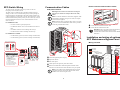
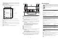
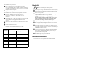
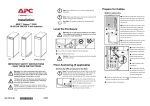
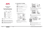
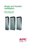
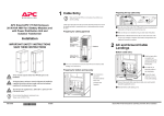
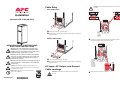
Cable Entry Caution: Power terminal lug diameter is 8 mm. Torque value is 6 Nm.. Rear Cable Entry 2 3 Installation 4 Symmetra PX 10-40 kW 208 V Loosen the screws to remove the plate. Emergency Power OFF Switch Keep EPO wire routing isolated and use separate EPO conduit Punch holes as required and reinstall the panel before mounting the wiring hardware. Bottom Cable Entry AC DC Input Output (Optional XR) AC Input Connect power input and output wiring to terminate as shown. Route the input and output cables in separate conduits. IMPORTANT SAFETY INSTRUCTIONS SAVE THESE INSTRUCTIONS Warning: ALL safety instructions in the Safety Sheet 990-2984 must be read, understood, and followed when installing the UPS system. Failure to do so could result in equipment damage, serious injury, or death. Warning: The UPS system has no built-in disconnection devices for AC output and DC input. An AC output overcurrent protection and AC output disconnect must be provided by the customer. Warning: After the UPS has been electrically wired, do not start it up. Start-up is commissioned to APC-authorized personnel only. Caution: For customer-supplied external batteries, overcurrent protection and a disconnection device for the battery circuits must be provided. Note: Ensure that the unit is in its final location prior to the installation. 990-4063F-001 *990-4063F- Loosen the screws to remove the plate. Punch holes as required and reinstall the panel before mounting the wiring hardware. AC Input, AC Output, and Ground Cable Landings Caution: Ensure clockwise phase rotation and neutral location. 07/2007 Emergency Power OFF Switch Keep EPO wire routing isolated and use separate EPO conduit AC DC Input Output (Optional XR) AC Input Make ground connections as shown. EPO Switch Wiring Communication Cables The UPS must be connected to either a dry contact or a 24 Vdc Emergency Power Off (EPO) switch. How to connect communication cables Side panel removal System The EPO circuit is considered Class 2 and SELV (Safety Extra Low Voltage). A SELV circuit is isolated from primary circuitry through an isolating transformer and designed so that under normal conditions, the voltage is limited to 42.4 Vac peak or 60 Vdc. SELV and Class 2 circuits must be isolated from all primary circuitry. Do not connect any circuit to the EPO terminal block unless it can be confirmed that the circuit is SELV or Class 2. For installations in US. – CL2Class 2 cable for general purpose use. Warning: Ensure Total Power Off before removing the side panel (see Total Power Off procedure in the Safety Sheet). Note: Use 20-foot standard Cat 5 data cable (supplied). If the cable length is inadequate, a longer Cat 5 cable, or couplers, can be used (not supplied). Note: If bottom routing is required, follow steps 1 to 5 below to gain access to the communication cables. If not, proceed to Connecting communication cables. ly ote Rem View Power puter Com ce Interfa ay Displ e terfac ter In ompu ay / C Displ Status X/TX Link-R Reset Port Port 2 et werN 06 Po AP96 r apte k Ad or Netw 1 ions unicat omm XR C r onito ry M Batte Connect the network communication cable. Connect the XR communication cable. INTELL IGENC E MODUL E INTELL IGENC E MODUL E – CL2XLimited use cable for dwellings and raceways. For installations in Canada. See Also: Refer to the guide supplied with the battery enclosure for further details on how to connect communication cables between the UPS and the XR Battery Enclosures. – CL2RCertified, type ELC (Extra-Low-Voltage Control Cable). – CL2XCertified, type ELC (Extra-Low-Voltage Control Cable). Installation and wiring of optional APC Maintenance Bypass Panel ? Emergency shut-down with internal supply N/O EPO Control Supp -T 10Base – CL2PPlenum cable for use in a vertical shaft or from floor to floor. – CL2R Racer cable for use in dwellings and raceways. Power N/C EPO Control Wiring overview XR Commu nication s 4 Ground 8 Ground 3/2 Relay Coil 1 Internal Power +24V Supply 7/6 Relay Coil 2 Internal Power +24V Supply 1 5 EPO AC Power DC Power DOCU MENT STOR AGE J6 MBP (optional equipment) Interface wiring Input/Output Wiring of Ancillary Equipment Battery Enclosure (Optional, 4 Max.) UPS 1/2 Unlock the right-side panel using key. Battery Breaker present 3/4 Ext. battery fuse/Battery Breaker 1 (N/O position) 5/6 Ext. battery fuse/Battery Breaker 2 (N/O position) 7/8 Temp. sensor, ext. battery 9/10 Temp. sensor, ext. battery present 11/12 Iso. trafo temp. switch (N/C position) 13/14 Iso. trafo temp. switch present EPO Control for PSX PDU J6 2 4 1 3 1 Internal Power +24V Supply 2/3 Relay Coil 1 Ground 4 Emergency Power OFF Switch Keep EPO wire routing isolated and use separate EPO conduit AC DC Input Output (Optional XR) AC Input Output Power Depress the latches. Pull out the panel. Lift the panel at an angle away from the enclosure. Route the communication cables through the front holes of the enclosures. Exit the enclosures from the bottom or top as required. Note: If your UPS has been installed between devices and side panels cannot be removed, the Bypass Static Switch Module can be removed to gain access. 2 Input Power APC Maintenance Bypass Panel installation and wiring procedure UTILITY INPUT 208V WYE 4 WIRE + GROUND SYSTEM OUTPUT 208V 4 WIRE + GROUND Mount the APC Maintenance Bypass Panel (MBP) on a wall close to Specifications Caution: All electrical power and power control wiring must be installed by a qualified electrician, and must comply with local and national regulations for maximum power rating. the UPS according to the illustration below: MAINTENANCE BYPASS PANEL A = 25.99 in. / 660 mm L1 L2 L3 N G L1 X001 UTILITY INPUT X002 L1 L2 L3 N 1 2 3 4 5 6 L3 N Note: All current values are based on a 40 kW maximum configuration of the UPS. G X004 UTILITY OUTPUT X003 X010 G L2 7 8 9 L1 10 L2 L3 N G Input L1 L2 L3 N AC INPUT . Fixing holes in the back of box G L1 1 2 3 4 5 6 7 8 9 10 13 14 L2 L3 N G AC OUTPUT J2 B = 33.84 in. / 860 mm Maintenance Bypass Monitor Board SYMMETRA PX UPS Input voltage 3-Phase 208 V (166 V-240V ) Input current (nominal, per phase) 123 A Maximum input current (continuous, at minimum 162 A mains voltage) Input current protection (external to UPS, not supplied) 175 A *note 4 Input frequency 40-70 Hz Maintenance Bypass Panel wiring checklist Ensure that both the DC breaker and the system enable switch are in the OFF or STAND-BY positions. Connect the cables from the upstream utility to the main input Torque terminal screws to 1.6-1.8 Nm and terminal bolts to 6 Nm. Verify wires in terminal block X010. Wires 1-10 connect to equipment interface 1-10. terminals on the MBP. Connect the cables from the UPS AC input to the input terminals on the MBP. Apply power to system input of MBP and measure voltages at input terminal block (X001). Measure and record voltages below between: L1 and Neutral:________ L2 and Neutral:____________ L3 and Neutral:__________ Measured voltages must be 96 and 130. If not, STOP! Verify correct wiring from the power source to the input wiring connections and repeat the procedure. Connect the cables from the UPS AC output to the output terminals on the MBP. Connect the cables from the MBP mains output terminals to the load equipment/distribution. Connect control wires between the UPS and the MBP. Ensure that the phase rotation is correct. Ensure that the wiring is correct. Switch on Q001, Q003, and Q002. Measure and record voltages between input and output points on the Symmetra PX L1 input and L1 output:_______ L2 input and L2 output:________ L3 input and L3 output:_______ Measured voltages must be 0 Volt +/- 2 Volt. If not, STOP! Verify correct wiring from MBP to the Symmetra PX. Successful completion of steps 1 through 7 indicates that the MBP is properly installed and functioning correctly. Turn off breakers and switches and shut down input power to the system. Reinstall all wiring access panels on the Symmetra PX. Output Output voltage (on line) 3-Phase 208 V Output current (nominal, per phase) 111 A Maximum output current (in bypass only at 125% 139 A overload, per phase) Neutral output current (with 100% switch mode load) 192 A *note 7 Output current protection (external to UPS, not supplied) 150 A *note 5 Output frequency (on line, in bypass) Synchronized to input Output frequency (on battery) 50/60 Hz Overcurrent device and disconnect switch for external safety DC bus voltage +/- 192 V DC voltage rating of the battery supply 250 V Maximum available battery supply fault current 10 kA Notes Recommended source connection. Input electricity to be provided from a dedicated, grounded 4-wire WYE utility power source with a grounded neutral. If a grounded 3-wire utility is present, a Delta-to-WYE isolation transformer on UPS input is required. Ensure clockwise voltage phase rotation (L1,L2,L3). 3 Checklist Recommended current protection. Input: 175 Amp. 3-Pole AC circuit breaker with 30 kAIC. Note: If your installation does not include an Isolation Transformer and a MBP (optional equipment), use a 175 Amp Class “J” current limiting fuse on each input phase. Output: 150 Amp 3-pole AC circuit breaker with 30 kAIC. Recommended wiring for a 104oF (40oC) temperature environment. Ensure all power wiring is torqued to a minimum of 53 lb-in (6 Nm). Ensure that the system enable switch and the DC breaker are in the OFF or STAND-BY position. Apply utility power to the system input and measure the voltage at o o Input wires: 2/0 AWG 90 Co (194 F)o rated copper wire. Output wires: 1/0 AWG 90 C (194 F) rated copper wire. Refer to NEC Articles 310-15, 310-16 and 315 for further information. Neutral output wires: rate for 173% of output phase current if feeding all Switch Mode Power Supply loads without power factor correction. Ground wires: sized in accordance with NEC Article 250-122 and Table 250-122. the input terminal block. Record voltages between: L1 and N:______________ L2 and N:_____________ L3 and N:_______________ Measured voltage must be between 96 and 130. If not, STOP! Verify correct wiring (correct location of N) from the power source to the input wiring connections. Repeat Step 3. Verify clockwise phase rotation using a phase rotation meter. Turn on system enable switch. Wait 1 minute for system to self test. Ignore display warning (fault light will be on). Maximum cable sizes: 250 kcmil. Recommended cable lugs and crimping tools. Manufacturer: Framatome Connectors International (FCI) (see table). Cable Size (AWG) Note: Do not install power or battery modules. Test the EPO switch. The system enable switch should trip to the STAND-BY position, and the system should shut down completely. If not, check the connections and the EPO switch to ensure that they are installed and functioning correctly. Successful completion of steps 1 through 6 indicates that the UPS Terminal bolt diameter: 8 mm Cable Lug Type Crimping Tool Die 8 YA8CL2TC38 MD7-34R W8CVT 6 YA6CL2TC38 MD7-34R W5CVT 4 YA4CL2TC38 MD7-34R W4CVT 3 YA3CL2TC38 Y35 U3CRT 2 YA2CL2TC38 MD7-34R W2CVT 1 YA1CL2TC38 MD7-34R W1CVT 1/0 YA25CL2TC38 MD7-34R W25VT 2/0 YA26CL2TC38 MD7-34R W26VT 3/0 YA27CL2TC38 MD7-34R W27VT 4/0 YA28CL2TC38 MD7-34R W28VT wiring is properly installed and functioning correctly. Turn off breakers and switches and shut down utility power to the system input. See Total Power Off procedure. Reinstall all wiring access panels on the UPS. Contact Information For local, country-specific centers: go to www.apc.com/support/contact or see the back cover of the operation manual for phone numbers. 4