1
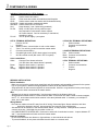
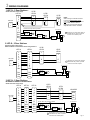
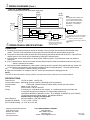
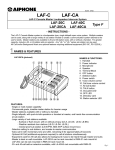
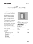
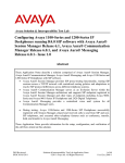
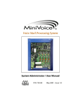
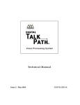
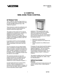
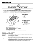
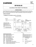
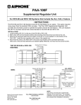
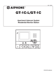
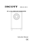
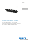
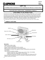
Special
Order
Products
LEF-3L
3-Call Master Station with Selective Control Capability (Door Release or Camera Call-up)
Used with LE-D, LE-DA, LE-DL, LS-NVP/B Door Stations
- SUPPLEMENT TO LEF INSTRUCTIONS The LEF-3L is a compact, wall or desk mount master station able to selectively release a door or call up a camera.
Used with any LE- or LS-series remote station, communication can be established with each station by selecting
the channel on the master station. While the channel is selected, pressing the door release button (left of TALK
button) will release only the associated door. When used for camera call-up, a relay closure will be maintained as
long as a station is selected. The system can have up to four stations, in any combination of masters or door
stations (e.g. 2 masters and 2 doors). Master-to-master communication is also a standard feature.
(If communication between masters is not required, multiple LEF-3L's can be used to talk to 3 door stations.
1 NAMES & FEATURES
Speaker
Microphone
Station Call-in LEDs
Occupied LED
Station Selectors
TALK Button
OFF Button
Voice
Volume Control
Door Release
Button
FEATURES:
· Selective door release control
· CCTV camera call-up capability
· Single or multiple masters can be used in a system
· Master to master communication in a multi-master system
· Single talkpath, with push-to-talk operation at master, and hands free communication
at sub station
· Large variety of sub stations available
- Surface or flush mount, with or without privacy (LE-A, LE-AN, LE-B, LE-BN)
- Weather resistant door stations (LE-D, LE-DA, LE-DL)
- Vandal proof sub station (LS-NVP/B, and optional SBX-DGV surface mount box)
· Subs call in with momentary tone and LED, remaining lit for approximately 20 seconds
· Selective calling to sub stations
Pg. 1
2 COMPONENTS & WIRING
Individual Components for LEF-3L System:
LEF-3L
3-call master with selective door release
LE-D
Surface mount door station
LE-DA
Flush mount door station with stainless steel faceplate
LE-DL
Surface mount metal door station with illuminated directory
LS-NVP/B Vandal and weather resistant sub station
SBX-NVP Surface mount box for LS-NVP/B
SA-1
Surge Arrestor (1 per 2 wires being protected)
RY-PA
Relay, 12V DC input, N/O dry closure output.
One required for each contact closure required
off of each channel. Can be momentary or maintained,
according to wiring.
PS-12C
12V DC power supply, 1 per system
LEF-3L TERMINAL DEFINITIONS:
+
Positive 12V DC
Negative
1~3
Station number, communication to sub or other master
C
"CALL", for receiving a call from another master station
E
Common communication
R
Occupied light control (0V DC when system is occupied)
Y
All Call override control (Not used in LEF-3L system)
Color-coded Wires:
White
Common Door release activation
(12V DC when door release button is pressed)
Brown
Negative when station 1 is pressed
Red
Negative when station 2 is pressed
Orange
Negative when station 3 is pressed
LE-D/LE-DA TERMINAL DEFINITIONS:
1
Station number
E
Common communication
Negative
LS-NVP/B TERMINAL DEFINITIONS:
Red
Station number
Black Common communication
Green Negative
LE-DL TERMINAL DEFINITIONS:
1
Station number
E
Common communication
+
Positive
Negative
WIRING & INSTALLATION:
Before Installation:
· Make sure you have the proper power supply(ies) and all necessary and compatible equipment for the system.
· Lay out your system in advance, assigning station numbers for all sub station locations.
· Surge protection for the intercom equipment is recommended. Add SA-1 surge arrestors for the power supply,
plus one per two wires connected to the master station.
Wire:
· Shielded wire is strongly recommended. Use the proper gauge for the distance being run.
· Wiring between masters must be a multi-conductor cable. If more than one cable is used to connect masters,
the "E", "C", and number terminal wires must be in the same jacketed cable. If necessary, run multiple "E"
wires, one in each cable.
Wiring Method:
· Run intercom cables at least 20" away from all AC wiring, fluorescent lights, dimmer switches, and other
electrical or electronic devices. Intercom wiring can cross AC wires at 90 degrees.
· Sub stations can be homerun to the nearest master station, or daisy-chained. If daisy-chained, include 2
common wires plus 1 individual wire per station on the run.
· In a SINGLE MASTER SYSTEM ONLY: Subs can be wired with 2 conductors homerun. Jumpers between "E"
and "-" must be attached on all subs and at the master station.
Intercom Locations:
· Do not install intercoms near dimmer or light switches, or other electrical wall devices.
· To prevent feedback, do not place sub stations back-to-back on a common wall.
Pg. 2
3 WIRING DIAGRAMS
1 LEF-3L, 3 Door Stations LE-D/
LE-DA
Shown with door release relays
LEF-3L
PS-12C
+
1
2
3
E
+
C
R
Y
Wht
Brn
Red
Org
1
LE-D/
LE-DA
1
LE-D/
LE-DA
E
-
E
-
1
E
-
12V DC when "key" button is pressed
Blk
RY-PA
Dr. #1
NOTE:
When running 2 conductors homerun
to each sub (single master system
only), leave jumper attached between E
& - on master and door stations.
Otherwise, remove jumpers and use
separate wires for E and - terminals.
AC Transformer
A Momentary dry closure when station is
A
Yel
Blk
RY-PA
Dr. #2
Yel
A
Blk
RY-PA
Dr. #3
selected and "key" button is pressed.
Connect to door strike & power.
A
Yel
2 LEF-3L, 2 Door Stations
Shown with door release relays
Master-to-Master communication shown using channel 3
PS-12C
+
LEF-3L
LEF-3L
1
2
3
C
E
+
R
Y
Wht
1
2
C
3
E
+
R
Y
Wht
Brn
Red
Org
Brn
Red
Org
LE-D/
LE-DA
LE-D/
LE-DA
1
1
E
-
E
-
A Momentary dry closure when station is
selected and "key" button is pressed.
Connect to door strike & power.
AC Transformer
Blk
RY-PA
Dr. #1
Yel
A
A
Blk
RY-PA
Dr. #2
Yel
3 LEF-3L, 3 Door Stations
No Master to Master Communication
Shown with door release relays
PS-12C
+
LEF-3L
LEF-3L
LEF-3L
1
2
3
C
E
+
R
Y
Wht
Brn
Red
Org
1
2
3
C
E
+
R
Y
Wht
Brn
Red
Org
1
2
3
C
E
+
R
Y
Wht
Brn
Red
Org
LE-D/
LE-DA
LE-D/
LE-DA
1
LS-NVP/B
1
Red
E
-
Blk
Grn
E
-
12V DC when "key" button is pressed
Blk
RY-PA
Dr. #1
Yel
AC Transformer
A
Blk
RY-PA
Dr. #2
Yel
A
Blk
RY-PA
Dr. #3
A
Yel
A Momentary dry closure when station is
selected and "key" button is pressed.
Connect to door strike & power.
Pg. 3
3 WIRING DIAGRAMS (Cont.)
1 LEF-3L, 2 Door Stations Shown with both Door Release and CCTV Camera Call-up relays
LE-D/
LE-DA
LEF-3L
PS-12C
+
1
2
3
C
E
+
R
Y
LE-D/
LE-DA
1
1
E
-
Blk
RY-PA
Cam. #1
Yel
E
B
NOTE:
This diagram shows separate E &
- wires. In single master system
only, one wire can be used for E/when jumper remains attached
between E & - on master and
door stations.
Blk
* Diode
RY-PA
Cam. #2
Yel
B
* Diode
Wht
Brn
Red
Org
Blk
RY-PA
Dr. #1
4 OPERATIONS & SPECIFICATIONS
Yel
A
Blk
RY-PA
Dr. #2
Yel
A
* Diode: 1N4001 value.
Required for door strike relay
only when 2 relays are used
on any one channel.
A Momentary dry closure when station is
selected and "key" button is pressed.
Connect to door strike & power.
B Constant closure as long as station is
selected.
OPERATION:
1. Pressing the call button at the door station will activate a tone, plus light the red channel LED indicator at the
master. The tone will be momentary, and the light will remain activated for approximately 20 seconds.
2. The person at the master station answers the call by pressing the selector button with the lit LED. If the LED has
already gone out, the call can still be answered by pressing the selector button.
3. Communication at the master station is "press-to-talk, release-to-listen". Communication at the door station is
hands free.
4. If the "Camera Call-up" feature is included, the associated relay will provide a maintained closure as long as the
station is selected at the master.
5. With communication established to a door station, pressing the door release button (marked with key symbol, left
of TALK button) will activate the door release mechanism at the corresponding door. The door release button
will
be non-functional if a station button is not pressed.
6. When the conversation is completed, the OFF button must be pressed to disengage the call.
NOTE:
The LEF-3L does not have the "privacy feature", and also cannot send a call tone to the remote stations.
SPECIFICATIONS:
Power Source:
12V DC at master. Use PS-12C.
Communication Output: 800mW @ 20 ohms (receive); 500mW @ 20 ohms (transmit)
Communication:
Push-to-talk, release-to-listen at master station. Hands free at sub station.
Calling:
Master to sub: By voice
Sub to master: Call tone and LED
Wiring:
2 common plus 1 individual per sub, looped; or 3 conductors homerun from each sub.
2 conductors homerun from each sub in a single-master system only.
Use Aiphone #822202 or #821802 ( 2 cond., 22 or 18AWG), or #822203 (3 cond. 22AWG)
12 conductors between master stations. Use Aiphone #822212.
Shielded cable is strongly recommended.
Wiring Distance:
650' with 22AWG; 1,600' with 18AWG.
Dimensions (HxWxD): 7-1/16" x 5-5/8" x 2-3/16"
RY-PA Contact Rating: 1A, 110V AC or 24V DC
Aiphone Communication Systems
1700 130th Ave. N.E.
Bellevue, WA 98005
(425) 455-0510
FAX (425) 455-0071
TOLL FREE TECHNICAL SUPPORT:
(800) 692-0200
TOLL FREE FAX LINE:
(800) 832-3765
E-MAIL: [email protected]
LEF-3L Instr.
0101BKJD