1
ALESIS
Q20
User Manual
Introduction
Thank you for purchasing the Alesis Q20 Professional 20-Bit Master Effects
Processor. To take full advantage of of the Q20Õs fuctions, and to enjoy long and
trouble free use, please read this userÕs manual carefully.
How To Use This Manual
This manual is divided into the following sections describing the various modes of
the Q20. Though we recommend you take time to read through the entire manual
once carefully, those having general knowledge about effects devices should use the
table of contents and index to reference specific functions while using this device. If
you are planning to use the digital I/O, read Chapter 7 carefully.
Chapter 1: Setting Up. Deals with the necessary preparation before using,
including connections to other components, such as instruments, mixing consoles, and
multitrack recorders, as well as digital connections to ADAT.
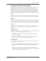
Chapter 2: Your First Session with the Q20. A basic introduction to getting the unit
up and running, auditioning the factory Programs, adjusting levels, comparing and
storing edited Programs.
Chapter 3: Overview. A detailed look at the signal processing capabilities of the
Q20, the concepts of multi-effect programming, and a description of the many
available effects.
Chapter 4: Making Your Own Programs. A guided tour for programming typical
single and multi-effect applications.
Chapter 5: Description of Controls. A ÒdictionaryÓ of all parameters, buttons and
connectors, including Global and MIDI mode parameters.
Chapter 6: Advanced Applications. Advanced uses of the Q20, such as MIDI
functions, Modulation, Local Generators, footswitches and using Òtap tempoÓ to
control delay times.
Chapter 7: Digital Connections. How to use the Q20Õs digital ins and outs in an alldigital studio.
Chapter 8: Troubleshooting. Contains the Troubleshooting Index, maintenance and
service information, and MIDI implementation chart.
Conventions
The buttons, knobs, and rear panel connectors are referred to in this manual just as
their names appear on the Q20, using all capital letters and in brackets (Examples:
[PROGRAM] button, [< BLOCK] button, [VALUE/ENTER] knob/button, [DIGITAL
IN] connector, etc.).
✪
When something important appears in the manual, an icon (like the one on the left)
will appear in the left margin. This symbol indicates that this information is
vital when operating the Q20.
Q20 Reference Manual
1
2
Q20 Reference Manual
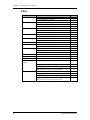
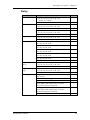
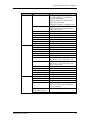
Contents
CONTENTS
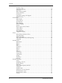
1: Setting Up ................................................................................ 7
Unpacking and Inspection.......................................................................................7
AC Power Hookup..................................................................................................7
Line Conditioners and Protectors.................................................................7
Audio Connections..................................................................................................8
Typical Applications.................................................................................8
Interfacing Directly with Instruments .........................................................9
Interfacing to a Mixing Console...................................................................10
When to use Balanced Connectors................................................................15
Avoiding Ground Loops...............................................................................15
MIDI .....................................................................................................................16
Digital Connections................................................................................................16
Footswitches..........................................................................................................17
Advance ....................................................................................................17
Bypass.......................................................................................................17
Tap Tempo .................................................................................................18
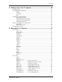
2: Your First Session With The Q20 .......................................... 19
Powering Up ..........................................................................................................19
Setting Levels........................................................................................................19
The Value/Enter Knob............................................................................................20
Adjusting the Display Contrast ..................................................................20
Auditioning Internal Programs................................................................................21
Switching Between Preset and User Banks ..................................................21
Example Programs..................................................................................................22
96: ÒVerbOfMyDreamsÓ .............................................................................22
97: ÒGuitar Rack Ó.....................................................................................22
98: ÒStereo PlatesÓ .....................................................................................22
Adjusting Effects Levels..........................................................................................23
Comparing an Edited Program to its Original Settings .............................................24
Restoring an Edited Program to its Original Settings ...............................................24
Storing Edited Programs .........................................................................................25
Auditioning Programs before Storing...........................................................25
Bypassing Effects...................................................................................................26
Global Direct Signal Muting ...................................................................................26
3: Overview .................................................................................. 27
The Architecture of the Q20 ...................................................................................27
What is a Block? .......................................................................................27
Selecting and Editing Blocks.......................................................................27
Routing ÒPatch CordsÓ Between Blocks .......................................................28
Quick Route ...............................................................................................29
Setting the Routing Levels..........................................................................29
The L/R IN................................................................................................30
Reaching the Outputs - L/R OUT ................................................................30
Limit Handling......................................................................................................30
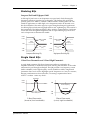
Equalization ..........................................................................................................32
Filters .......................................................................................................32
Shelving EQs .............................................................................................33
Single Band EQs.........................................................................................33
Q20 Reference Manual
3
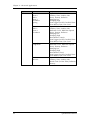
Contents
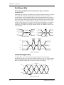
Multiband EQs ...........................................................................................34
5 Band Graphic EQ.....................................................................................34
Resonator...................................................................................................35
Mono/Stereo Tremolo .................................................................................35
Stereo Simulator........................................................................................35
Overdrive..................................................................................................36
Triggered Panning with Doppler.................................................................37
Phase Inverter ...........................................................................................38
Pitch Effects ..........................................................................................................39
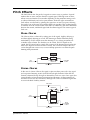
Mono Chorus ..............................................................................................39
Stereo Chorus.............................................................................................39
Quad Chorus ..............................................................................................40
Mono Flanging............................................................................................40
Stereo Flanging..........................................................................................41
Phasor.......................................................................................................41
Mono/Stereo Lezlie Cabinet .......................................................................41
Pitch Shifter .............................................................................................42
Pitch Detune..............................................................................................42
Ring Modulator ..........................................................................................42
Triggered Flanging .....................................................................................42
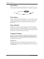
Delay....................................................................................................................44
Mono Delay and Stereo Delay ....................................................................44
Ping Pong Delay.........................................................................................44
Multi Tap Delay........................................................................................44
Tap Tempo Mono Delay and Ping Pong.........................................................44
Sampling ...................................................................................................45
Reverberation ........................................................................................................49
Mono Room.................................................................................................49
Room 1.......................................................................................................49
Hall 1........................................................................................................49
Plate 1.......................................................................................................49
Chamber 1 .................................................................................................49
Room 2.......................................................................................................49
Hall 2........................................................................................................49
Plate 2.......................................................................................................50
Chamber 2 .................................................................................................50
Large Plate ................................................................................................50
Large Room ................................................................................................50
Spring........................................................................................................50
Nonlinear ..................................................................................................50
Reverse......................................................................................................50
Reverb Parameters.................................................................................................51
Decay........................................................................................................51
Damping Ð Hi & Lo ....................................................................................51
Reverb Density ..........................................................................................51
Diffusion ...................................................................................................51
Input High Frequency Roll Off....................................................................52
Predelay....................................................................................................52
Predelay Mix .............................................................................................52
Reflection Level and Spread.......................................................................52
Reverberation Swirl...................................................................................52
Reverberation Attack.................................................................................52
Gating .......................................................................................................53
4
Q20 Reference Manual
Contents
4: Making Your Own Programs ................................................ 55
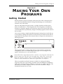
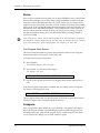
Getting Started ......................................................................................................55
Programming A Single Block...................................................................................56
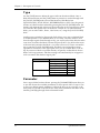
Type..........................................................................................................56
Routing ......................................................................................................57
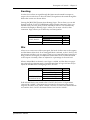
Parameter..................................................................................................59
Mix............................................................................................................60
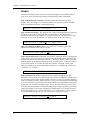
Programming Multiple Blocks.................................................................................61
Defining New Blocks..................................................................................61
Deleting Unnecessary Routings ...................................................................62
Patching In The New Blocks.......................................................................62
Adjusting Parameters .................................................................................62
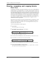
Moving , Swapping and Copying Blocks ..................................................................64
Block Move................................................................................................64
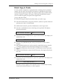
Block Copy & Paste....................................................................................65
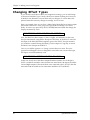
Changing Effect Types............................................................................................66
5: Description of Controls........................................................... 67
Front Panel ............................................................................................................67
Input Level ................................................................................................67
Output Level..............................................................................................67
LED Meter .................................................................................................67
Display.....................................................................................................67
Value/Enter...............................................................................................68
Program.....................................................................................................69
Store..........................................................................................................70
Compare....................................................................................................70
Bypass.......................................................................................................71
< Block >...................................................................................................71
< Page > ....................................................................................................71
Type..........................................................................................................72
Parameter..................................................................................................72
Routing ......................................................................................................73
Mix............................................................................................................73
Global .......................................................................................................74
Name ........................................................................................................76
MIDI .........................................................................................................76
Modulation................................................................................................78
Power ........................................................................................................78
Rear Panel .............................................................................................................79
Power ........................................................................................................79
MIDI In......................................................................................................79
MIDI Thru/Out ..........................................................................................79
Bypass.........................- Bypass Footswitch...............................................79
Advance ......................- Program Advance Footswitch ...............................79
48kHz in ......................- Sample Clock Input..............................................79
Digital In ....................- ADAT Digital Audio In........................................80
Digital Out..................- ADAT Digital Audio Out.....................................80
Digital In ....................- S/PDIF Digital Audio In ......................................80
Digital Out..................- S/PDIF Digital Audio Out ...................................80
Left/Right In...............- Analog Audio In...................................................80
Left/Right Out ............- XLR Analog Audio Out .........................................80
Left/Right Out ............- 1/4Ó Analog Audio Out .........................................80
Q20 Reference Manual
5
Contents
Effect Parameters...................................................................................................81
Equalization ..............................................................................................81
Pitch .........................................................................................................82
Delay ........................................................................................................83
Reverberation ............................................................................................84
6: Advanced Applications .......................................................... 87
MIDI Functions.......................................................................................................87
Global MIDI Channel.................................................................................87
Receiving Program Changes........................................................................87
Selecting Banks via MIDI...........................................................................88
Program Change Table ...............................................................................88
SysEx Storage ............................................................................................89
MIDI Thru .................................................................................................90
Realtime Modulation Functions ..............................................................................91
Selecting the Modulator.............................................................................91
Choosing a Target ......................................................................................92
Choosing a Source.......................................................................................95
Setting the Amplitude ...............................................................................95
Local Generators ........................................................................................96
Footswitch Controls ...............................................................................................101
Program Advance.......................................................................................101
Bypassing Effects.......................................................................................101
Block Bypass via MIDI ..............................................................................102
Controlling Delay Time via Tap Tempo ......................................................102
MIDI Control of Tap Tempo Delay..............................................................103
7: Digital Connections ................................................................. 105
Overview ..............................................................................................................105
Digital Clock Synchronization ...............................................................................105
Connections............................................................................................................107
To a Single ADAT ......................................................................................107
To Two or More ADATs...............................................................................108
To Two or More ADATs with a BRC or AI-2.................................................109
To a Digital Mixer .....................................................................................109
To the AI-1 ................................................................................................110
From a QuadraSynth or QS-Series Synthesizer ...........................................110
Routings.................................................................................................................111
To specific ADAT tracks.............................................................................111
From ADAT through the Q20 back to ADAT................................................112
From the QuadraSynth or QS-Series through the Q20 back to ADAT...........113
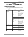
8: Trouble-Shooting..................................................................... 115
Trouble-Shooting Index ..........................................................................................115
Checking the Software Version ..............................................................................116
Re-initializing ......................................................................................................116
Total Reset ............................................................................................................116
Error Messages .......................................................................................................117
Maintenance/Service .............................................................................................118
Refer All Servicing To Alesis......................................................................118
Obtaining Repair Service ...........................................................................118
MIDI Implementation Chart ..................................................................................119
Specifications............................................................................... 120
Effects Processing Index............................................................ 122
6
Q20 Reference Manual
Contents
Q20 Reference Manual
7
Setting Up - Chapter 1
CHAPTER 1
SETTING UP
Unpacking and Inspection
Your Q20 was packed carefully at the factory, and the shipping carton was
designed to protect the unit during shipping. Please retain this container in the
highly unlikely event that you need to return the Q20 for servicing.
The shipping carton should contain the following items:
¥
¥
¥
¥
¥
✪
This instruction manual
Alesis Q20 with the same serial number as shown on shipping carton
AC Power Cable
Alesis warranty card
Quick Reference Guide
It is important to register your purchase; if you have not already filled out your
warranty card and mailed it back to Alesis, please take the time to do so now.
AC Power Hookup
The Q20 includes an internal universal power supply which is compatible with any
line voltage from 90-265 VAC, 50-60 Hz. It also includes a removable IEC power
cable suitable for use in the country shipped to.
Note that the Q20 uses a soft power switch which will turn the unit on when
plugged in. It is good practice to turn your mixer inputs or returns down while
connecting the Q20.
✪
Alesis cannot be responsible for problems caused by using the Q20 or any associated
equipment with improper AC wiring.
Line Conditioners and Protectors
Although the Q20 is designed to tolerate typical voltage variations, in todayÕs
world the voltage coming from the AC line may contain spikes or transients that
can possibly stress your gear and, over time, cause a failure. There are three main
ways to protect against this, listed in ascending order of cost and complexity:
¥
Line spike/surge protectors. Relatively inexpensive, these are designed to
protect against strong surges and spikes, acting somewhat like fuses in that
they need to be replaced if theyÕve been hit by an extremely strong spike.
¥
Line filters. These generally combine spike/surge protection with filters that
remove some line noise (dimmer hash, transients from other appliances, etc.).
¥
Uninterruptible power supply (UPS). This is the most sophisticated option. A
UPS provides power even if the AC power line fails completely. Intended for
computer applications, a UPS allows you to complete an orderly shutdown of a
computer system in the event of a power outage, and the isolation it provides
from the power line minimizes all forms of interferenceÑspikes, noise, etc.
Q20 Reference Manual
7
Chapter 1 - Setting Up
Audio Connections
The connections between the Q20 and your studio are your musicÕs lifeline, so use
only high quality cables. These should be low-capacitance shielded cables with a
stranded (not solid) internal conductor and a low-resistance shield. Although
quality cables cost more, they do make a difference. Route cables to the Q20
correctly by observing the following precautions:
¥
Do not bundle audio cables with AC power cords.
¥
Avoid running audio cables near sources of electromagnetic interference such as
transformers, monitors, computers, etc.
¥
Use balanced cables whenever possible.
¥
Do not place cables where they can be stepped on. Stepping on a cable may not
cause immediate damage, but it can compress the insulation between the center
conductor and shield (degrading performance) or reduce the cableÕs reliability.
¥
Avoid twisting the cable or having it make sharp, right angle turns.
¥
Never unplug a cable by pulling on the wire itself. Always unplug by firmly
grasping the body of the plug and pulling directly outward.
¥
Although Alesis does not endorse any specific product, chemicals such as Tweek
and Cramolin, when applied to electrical connectors, are claimed to improve
the electrical contact between connectors.
Typical Applications
The analog audio inputs and outputs are typically used in one of three ways:
¥
from one or two effect/aux send outputs of a mixer, and out to the effect return
inputs of the mixer; or,
¥
from a line-level instrument (like a guitar or keyboard with either a mono or
stereo output), and out to an amplifier or mixer input; or,
¥
from the stereo buss outputs of a mixer to a mix-down tape machine or
amplifier.
When used with a mono source, the Q20 is placed between the source and the
mixer/amplifier. Although the source may be mono, both the [LEFT] and [RIGHT]
outputs can be connected to the inputs of a mixer/amplifier if stereo processing
effects are desired. Alternatively, you could use the INSERTS on your mixer to
Òpatch inÓ only the left or right channel of the Q20. If using the effect sends of a
mixer, you have the advantage of sending any of the mixerÕs input channels to the
Q20Õs input(s), and have control over the level of each channel being sent.
There are other combinations of input and outputs possible when you begin using the
Alesis optical digital input and output. See the ÒDigital ConnectionsÓ section later
in this Chapter. For more information on interfacing with other digital audio
equipment, see Chapter 7.
8
Q20 Reference Manual
Setting Up - Chapter 1
Interfacing Directly with Instruments
✪
When connecting audio cables and/or turning power on and off, make sure that all
devices in your system are turned off and the volume controls are turned down.
The Q20 has two balanced inputs and two balanced outputs. These provide three
different (analog) audio hookup options:
¥
Mono. Connect a cable to the [L] INPUT of the Q20 from a mono source, and
another cable from the [L] OUTPUT of the Q20 to an amplification system or
mixer input.
¥
Mono In, Stereo Out. While still using a mono input, you could connect two cables
to the [L] and [R] OUTPUTS of the Q20 to a stereo amplification system or two
mixer inputs.
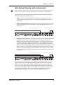
From Instrument or Effects Send
¥
To Amplifier or Mixing Console
Dual Mono or Stereo Source. The Q20 may be used with two different instruments
simultaneously, or with a stereo instrument. The hookup is the same; the
difference is in the routing used within a program. A program may process the
two inputs discretely, using blocks dedicated to a single channel (for example, a
delay for a guitar and a gated reverb for a bass), or process them in stereo (for
example, with the left and right outputs of a keyboard routed through two reverb
blocks). Connect two cables to the [L] and [R] INPUTS of the Q20 from two mono
sources or from the stereo output of the instrument, then connect two other cables
from the [L] and [R] OUTPUTS of the Q20 to a stereo amplification system or two
mixer inputs.
From Instrument or Effects Send
To Amplifier or Mixing Console
Note: In most cases when plugging an instrument directly into the Q20 , youÕll use
Programs which route the "dry" signal at the input(s) directly to the output(s),
where it will be mixed together with the effected signal to achieve the proper
wet/dry mix at the Q20's outputs. If the program doesn't include this routing, you
will only hear the effected signal by itself. Therefore, it may be necessary to edit
such programs to add these "dry" routes when using the Q20 directly with an
instrument. (The Factory Preset programs usually include these routes.)
Q20 Reference Manual
9
Chapter 1 - Setting Up
Interfacing to a Mixing Console
The Q20 handles mono or stereo sends at all system levels. The input circuitry of the
Q20 can easily handle +4 dBu levels (+17.5 dBu peaks), while having enough input
and output gain to interface with the lower -10 dBV signal levels of many recording
systems.
The Q20 may be connected to a mixing console in several ways. Usually, it is
connected to the auxiliary send and return controls of the mixer. Another method of
interfacing is to connect the unit directly to the insert send and return patch points
of the channel that is to be effected. Still another way of interfacing the Q20 to a
mixer or recording console would be in-line across the output of your mixing console.
This last setup would be used only if you needed to effect the entire mix.
Using the Aux Sends
Generally, mixing consoles provide two types of auxiliary sends: pre-fader sends for
creating a cue (headphone) mix, and individual, post-fader effect sends. Typically,
if a mixer has more than two sends per channel (4, 6 or 8, perhaps), the first two
sends are reserved for the cue sends, while the remaining sends are used to feed
effects. If you are using a mixer with more than two sends, connect the Q20 using
post-fader sends.
Using a mixerÕs aux sends poses a distinct advantage: each channel has its own
level control feeding the aux output (and eventually the Q20 input). This allows
you to make a mix of any channels you want to go to the effects by using the
individual channelsÕ aux send levels on the mixer. Most consoles also have aux
master controls, which set the overall level of each aux output.
Coming back from the Q20Õs outputs into the mixer, you have two options:
¥
connecting to dedicated return inputs, or
¥
connecting to channel inputs.
The former is good if your mixer provides dedicated inputs (called returns) for effect
devices like the Q20. If your mixer does not have these, or you have already used
them all, consider connecting the Q20 to channel inputs or unused tape returns. You
may also want to take advantage of better EQ, panning or automation options on
your consoleÕs channel inputs.
10
Q20 Reference Manual
Setting Up - Chapter 1
Setting the Effect/Dry Balance
No matter where you connect the output of the Q20 into the mixer, you are in control
of the balance between the mixerÕs channel inputs (the uneffected signal being
routed to the aux sends and the Mix) and the effect returns coming from the Q20. The
effect returns generally should only contain effected signal, and not have any
uneffected signal mixed with it (since these two signals are blended together at the
mixer).
If the Program you are using has the L/R IN connected to the L/R OUT, you may be
getting some dry, uneffected signal at the return. Generally, this is not desirable
when using the Q20 with a mixer, since the "dry" signal is already being heard
through the original channelÕs fader. Therefore, in a mixer application you will
want to cut the Q20Õs ProgramÕs path which connects the inputs to the outputs. This
can be done in three ways:
✪
¥
Go to the Mix parameters to bring down the direct level
¥
Go to the Routing function of each program and remove the patch cords
connecting the inputs to the outputs
¥
Turn on the Global Direct Signal Mute function. This is the easiest method.
Most Preset Programs route the L/R IN signal to the L/R OUT.When connecting to a
mixerÕs aux sends and returns. the Global Direct Signal Mute should be set to MUTE.
To remove all direct routings of inputs to outputs on all Programs simultaneously:
➀ Press [GLOBAL].
The [GLOBAL] LED will be lit.
➁ Press [< PAGE] once.
This selects Global Page 9. The display will read:
GLOBAL DIRECT SIGNAL: ON
➂ Turn the [VALUE/ENTER] knob to the right until the display reads ÒON.Ó
The next Program recalled which has the inputs routed to the outputs will not
display the patch cords for these connections nor will you hear any direct
uneffected signal at the outputs.
Q20 Reference Manual
11
Chapter 1 - Setting Up
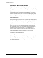
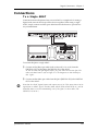
Mono In - Stereo Out. If you only want to feed the Q20 a mono input, but wish to
connect both of its outputs back to the mixer, you will need three audio cables.
Connect a cable from an effect send to the [L] INPUT of the Q20, another cable from
the [L] OUTPUT of the Q20 to an effect return or other mixer input, and another
cable from the [R] OUTPUT of the Q20 to an adjacent mixer input.
Left Input
Left and
Right
Outputs
Aux Send 3
Stereo Aux Returns
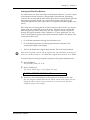
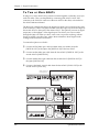
Stereo In - Stereo Out. This connection is similar to the one described above.
However, by utilizing two sends from the mixer, we add one more cord and can now
send a stereo signal to the Q20Õs inputs. Example, if you connected effect sends 3 and 4
to the [L] and [R] INPUTS, and had a stereo instrument (such as a keyboard)
connected to two channel inputs of the mixer (either one panned hard left and hard
right), you would send the left channel to send 3 and the right channel to send 4.
Alternatively, you could have two discrete effect sends between the Left and Right
channel, and process each separately within the Q20. For example, the Left
channel (from send 3) could be a chorus, and the Right (from send 4) could be a reverb.
This is similar to Dual Mono, described earlier.
Left Input
Right Input
Left and
Right
Outputs
Aux Send 3
12
Aux Send 4
Stereo Aux Returns
Q20 Reference Manual
Setting Up - Chapter 1
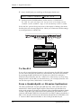
Using Inserts
By using individual channel inserts, you can dedicate the Q20 to a specific channel
(or pair of channels) on the mixer. The Insert connections on the back of the mixer
provide a way of ÒinsertingÓ external processing equipment into the signal path.
The insert occurs after the input amplifier, and before the main fader; essentially it
is the same as connecting the source (instrument or microphone) into the Q20 before
the mixerÕs channel input. However, some mixing consoleÕs inserts come after the EQ
section, and may therefore be different from the original signal.
Usually, insert connections require a special, stereo-splitting Y-cord to be connected
(one stereo plug provides both send and return while two mono plugs connect
separately to an input and output). These are known as TRS connectors (tip-ringsleeve). The tip of the stereo plug typically carries the send or output of the insert
jack, while the ring carries back the return. The sleeve represents a common ground
for both signals. Check the manual of your mixer because some are wired differently
(for example, having two separate jacks for send and receive).
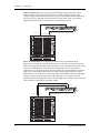
Mono. This involves connecting a 1/4" TRS (tip-ring-sleeve) to the Insert jack of a
single channel on a mixing console. The other end of the cable (which splits into
two, 1/4" mono connectors) are connected to the [L] INPUT and [L] OUTPUT,
respectively. If you do not hear any audio after making these connections, swap the
input and output cables at the Q20, as these may be wired backwards. If the cable is
color-coded, usually the red jack represents the send (which connects to the Q20Õs
INPUT) and black is the return (which connects to the OUTPUT).
Left Output
Left Input
Channel
Insert
Q20 Reference Manual
13
Chapter 1 - Setting Up
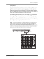
Stereo. In the case where a stereo instrument, such as a keyboard or sampler, is
connected to two separate channels of a mixing console, you will need two 1/4" TRS
cables, one for each channel. The connection is made in a similar fashion as
described above.
Right
Input
Right
Output
Left
Output
Left
Input
Right
Insert
Left
Insert
Using Main Outputs
When you want to effect everything on the mixer, you can connect the Q20 between
the mixerÕs outputs and the amplifierÕs or tape machineÕs inputs. This is done by
using two cables to connect the Left and Right Main Outputs of the mixing console to
the [L] and [R] INPUTs of the Q20. The [L] and [R] OUTPUTs of the Q20 are then
connected to a stereo amplifier, or two input channels of another mixing console (for
sub-mixing applications).
Left
Output
Left
Input
Right
Input
Left
Master
Out
Right
Master
Out
Right
Output
Power
Amp
Left
Input
Power
Amp
Right
Input
Out to Speakers
14
Q20 Reference Manual
Setting Up - Chapter 1
When to use Balanced Connectors
There are three options for connecting analog audio to the Q20: 1/4Ó unbalanced,
1/4Ó balanced (TRS) and XLR balanced. If your source and destination use balanced
connectors, you should try to stay balanced throughout the chain. Balanced cables
have a higher signal level and have the ability to cancel out hum and noise, which
can make your mixes quieter. XLR connectors have the added bonus of locking into
place, a good idea if you need to move your effects rack from place to place.
Keeping this in mind, your order of preference when connecting the Q20 to a mixer
should be to use the XLR connectors first, then to use balanced 1/4Ó cables, then
unbalanced 1/4Ó cables if your mixer doesnÕt have balanced sends and receives.
Avoiding Ground Loops
In todayÕs complex studio there are many opportunities for ground loop problems to
occur. These show up as hums, buzzes or sometimes radio reception, and can occur if a
piece of equipment ÒseesÓ two or more different paths to ground. While there are
methods to virtually eliminate ground loops and stray radio frequency interference,
most of the professional methods are expensive and involve installing a separate
power source just for the sound system. Here are some easy helpful hints that a
professional studio installer might use to zap those stray hums and buzzes.
➀ KEEP ALL ELECTRONICS OF THE SOUND SYSTEM ON THE SAME AC
ELECTRICAL CIRCUIT. Most stray hums and buzzes happen as a result of
different parts of the sound system being plugged into outlets of different AC
circuits. If any noise generating devices such as air conditioners, refrigerators,
neon lights, etc., are already plugged into one of these circuits, you then have a
perfect condition for stray buzzes. Since most electronic devices of a sound
system donÕt require a lot of current (except power amplifiers), itÕs usually safe
to run a multi-outlet box (or two) from a SINGLE wall outlet, and plug in all of
the components of your system there.
➁ KEEP AUDIO WIRING AS FAR AWAY FROM AC WIRING AS POSSIBLE.
Many hums come from audio cabling being too near AC wiring. If a hum occurs,
try moving the audio wiring around to see if the hum ceases or diminishes. If
itÕs not possible to separate the audio and AC wiring in some instances, make
sure that the audio wires donÕt run parallel to any AC wire (they should only
cross at right angles, if possible).
➂ TO ELIMINATE HUM IF THE ABOVE HAS FAILED:
A) Disconnect the power from all outboard devices and tape machines except
for the mixer and control room monitor power amp.
B ) Plug in each tape machine and outboard effects device one at a time. If
possible, flip the polarity of the plug of each device (turn it around in the
socket) until the quietest position is found.
C) Make sure that all of the audio cables are in good working order. Cables
with a detached ground wire will cause a very loud hum!!
D) Keep all cables as short as possible, especially in unbalanced circuits.
If the basic experiments donÕt uncover the source of the problem, consult your dealer
or technician trained in proper studio grounding techniques. In some cases, a Òstar
groundingÓ scheme must be used, with the mixer at the center of the star providing
the shield ground on telescoping shields, which do NOT connect to the chassis
ground of other equipment in the system.
Q20 Reference Manual
15
Chapter 1 - Setting Up
MIDI
MIDI is an internationally-accepted protocol that allows music-related data to be
conveyed from one device to another. The MIDI connections on the Q20 provide five
different functions:
¥
To recall programs using MIDI program change messages
¥
To control various parameters inside the Q20 in realtime via MIDI controllers
(example: A keyboardÕs mod wheel, or pedals, etc.)
¥
To convert MIDI Clock messages into delay settings on Tap Tempo Delay Blocks
¥
To send and receive SysEx (System Exclusive) dumps of individual programs or
the entire bank of programs for storage and retrieval purposes
¥
To pass-on MIDI information thru the Q20 to another MIDI device.
To connect the Q20Õs MIDI ports to another MIDI device:
➀ Connect a MIDI cable from the Q20Õs MIDI [THRU/OUT] connector to the MIDI
IN connector of the other MIDI device.
➁ Connect another MIDI cable from the Q20Õs MIDI [IN] connector to the other
MIDI deviceÕs MIDI OUT connector.
For more information about MIDI, refer to Chapter 6.
Digital Connections
Digital connections provide better fidelity than the analog inputs and outputs
because you avoid converting the audio from digital to analog (say from a digital
mixer), then to digital (Q20 input), then analog (Q20 output), then digital again
(back into the mixer).
The Q20 provides two formats for direct digital connections: ADAT Optical and
S/PDIF. The Alesis Optical interface provides two EIAJ fiber optic connectors for
[DIG IN] and [DIG OUT]. These connectors use a proprietary Alesis multichannel
format first introduced with the ADAT Multitrack Recorder. The Q20 can send
and/or receive digital audio directly to/from an ADAT (or other devices which use
the same optical interface). The S/PDIF inputs and outputs are provided on coaxial
(phono) jacks and conform to the consumer digital interface format (Sony/Philips
Digital Interface Format).
The proprietary Alesis Optical format carries up to 8 audio channels on a single
fiber optic cable. Since the Q20 has two channels (left and right), you may choose
two of the incoming 8 channels for the Q20 to process or output.
ADAT Optical fiber optic cables of various lengths are available from your Alesis
dealer. The shorter the cable, the better. The OC cable is 5 meters long (16'4") and
is the maximum length recommended. For S/PDIF connection, you should use good
quality video-type phono cables.
16
Q20 Reference Manual
Setting Up - Chapter 1
Footswitches
On the rear panel you will find two footswitch jacks labeled [ADVANCE] and
[BYPASS]. Any momentary single-pole/single-throw footswitch, normally open or
normally closed, will work for the two footswitch functions. These should be
plugged in prior to power-up so that the Q20 can configure itself for the type of
footswitch being used.
Advance
The [ADVANCE] jack lets you scroll through the Programs in memory by advancing
to the next higher numbered Program each time the connected footswitch is pressed.
The Q20 will Òwrap-aroundÓ whenever it reaches the end of available Programs
and the Advance footswitch is pressed again. You can set a range of Programs to be
used, thereby cutting off other Programs from being recalled in this manner. For
example, if you set the range to be User 0-10 through User 0-24, only Programs
within this range will be recalled using the Advance footswitch. If Program 0-24 is
selected and the footswitch is pressed again, Program 0-10 is recalled.
To adjust the Advance FootswitchÕs set of Programs:
➀ Press [GLOBAL].
The [GLOBAL] LED will light.
➁ Press [PAGE >] once.
This selects page 2, and the display will read:
FOOTSWITCH: Preset00 TO User1-99
➂ Turn the [VALUE/ENTER] knob to adjust the Program number to begin the range
(Preset 00 ÑÊ99, User 0-00 Ñ 1-99).
➃ Press [PAGE >] once and use the [VALUE/ENTER] knob to adjust the Program
number to end the range (Preset 00 ÑÊ99, User 0-00 Ñ 1-99).
Bypass
The Bypass footswitch jack lets you turn the Bypass function on and off from a
connected footswitch. When pressed, the [BYPASS] LED will light, indicating that
Bypass mode is enabled. When pressed again, the [BYPASS] LED will turn off.
For more information about Bypass mode, see Chapters 2 and 5.
Q20 Reference Manual
17
Chapter 1 - Setting Up
Tap Tempo
Either footswitch jack can be used to provide a tap tempo source for setting delay
time, provided the selected Program uses one of the two available tap tempo delay
types. This requires that you have defined an Effect Block as one of the two Tap
Tempo delay types, and that the desired footswitch jack has been selected for
controlling tap tempo. To select a footswitch jack for use with a Tap Tempo Delay:
➀ Press [GLOBAL].
The [GLOBAL] LED will light.
➁ Press [< PAGE] twice to select Global Page 8.
The display will read:
TAP TEMPO FOOTSWITCH: NONE
➂ Turn the [VALUE/ENTER] knob to select either the ADVANCE or BYPASS
footswitch jack, depending on which one you wish to use to control tap tempo.
Note that some programs can override these footswitch settings by re-assigning
pedals as Local Generator Sources in the Modulation pages. See Chapter 6 for more
information.
18
Q20 Reference Manual
Your First Session with the Q20 - Chapter 2
CHAPTER 2
Y OUR FIRST SESSION
W ITH T HE Q20
Powering Up
After making your connections, turn on the systemÕs power using this procedure:
➀ Before turning on the Q20Õs power, check the following items:
¥
¥
Have all connections been made correctly?
Are the volume controls of the amplifier or mixer turned down?
➁ Turn on the [POWER] switch on the front panel of the Q20.
Upon power-up, the Q20 will display the last selected Program, and the
[PROGRAM] buttonÕs LED will be lit. If this Program has been edited, the
display will indicate this by showing the word ÒEDITEDÓ, and by flashing the
Program Number and Name in the upper display.
➂ Turn on the power of the amplifier/mixer, and adjust the volume.
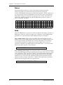
Setting Levels
Proper setting of the [INPUT LEVEL] and [OUTPUT] knobs is crucial in order to
achieve the maximum signal-to-noise ratio (the concentric knobs allow the Left and
Right Input levels to be adjusted separately). As a good starting point, set both
input and output level controls at about 2 o'clock or 65% of full. This will decrease
the possibility of overload distortion and keep the amount of background noise to a
minimum.
✪
For quietest operation, you should adjust the level of the source being sent to the
Q20 so that the green [-3dB] LEDs in the Q20Õs peak meter flash, but not so loud
that the red [CLIP] LEDs turn on. A nominal input sound make the -12dB LED turn on
Note: The Input and Output level controls effect the analog inputs and outputs only.
If you need to attenuate the digital inputs, you can do this in Page 2 of the Routing
pages. See Chapter 4 for more information.
Q20 Reference Manual
19
Chapter 2 - Your First Session with the Q20
The Value/Enter Knob
Located just to the right of the custom LCD display, the [VALUE/ENTER] knob is
used to select Programs and adjust parameter values that appear in the display.
However, it is not just a knob, it is also a button. Depending on what parameter you
are editing, the [VALUE/ENTER] knob will work in either one of two ways:
Immediate. The desired value is selected by turning the [VALUE/ENTER] knob,
and immediately takes effect. This is the case when adjusting most parameters.
Deferred. The desired value is selected by turning the [VALUE/ENTER] knob, but
the new value will only take effect after the [VALUE/ENTER] button has been
pressed. The newly selected value will flash in the display until it is selected in
this manner. If you change the parameter back to its original setting, the value in
the display will not flash. Also, if you go to another Page, or select another
Function (by pressing any button), the parameter will be left unchanged. If you went
back to look at the previous parameter, it will be set back to its original setting.
This mode is used for parameters that cause architectural changes such as changing
a BlockÕs function, effect type, and routing signals.
The [VALUE/ENTER] button can also be used to step through Pages in the currently
selected mode. Except when a value is flashing on and off in the display, the
[VALUE/ENTER] button ordinarily doubles for the [PAGE >] button. If you change
the value of a parameter that uses Òdeferred mode,Ó, you must press the
[VALUE/ENTER] button to enter the new value (the display will stop flashing),
and then you can press it again to move to the next Page (or to the next parameter, if
more than one parameter appears in the display). This is a feature for power users
who want to be able to move around the various pages quickly and make changes as
fast as possible.
✪
Unique Exception: When editing the Delay Time parameter of a Delay Block set to
either Tap Tempo Mono Delay or Tap Tempo Ping Pong, the [VALUE/ENTER]
button is used to ÒtapÓ in a tempo . See Chapter 6 for more information.
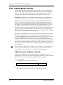
Adjusting the Display Contrast
Occasionally, the characters in the LCD display may be difficult to read,
depending on the viewing angle and existing lighting conditions. In such a situation,
adjust the contrast of the LCD display using the following procedure.
➀ Press [GLOBAL].
The display will go to the Global Mode Page 1.
ADJUST DISPLAY CONTRAST:
5
➁ Adjust the contrast by turning the [VALUE/ENTER] knob.
The displayÕs contrast and its value in the display will change.
20
Q20 Reference Manual
Your First Session with the Q20 - Chapter 2
Auditioning Internal Programs
You can audition the Programs in the Q20 by using the [VALUE/ENTER] knob or the
front panel buttons, whenever the Q20 is in Program mode (the [PROGRAM] buttonÕs
LED will be lit).
To select a Program using the [VALUE/ENTER] knob:
➀ Press [PROGRAM].
The [PROGRAM] buttonÕs LED will light.
➁ Turn the [VALUE/ENTER] knob.
Note: The [VALUE/ENTER] knob has two modes when used for selecting Programs:
Direct and Deferred. Direct mode immediately recalls the displayed Program as
you turn the [VALUE/ENTER] knob. Deferred mode lets you scroll through the
Programs in the display by turning the [VALUE/ENTER] knob, but you must press
the [VALUE/ENTER] button to actually recall a Program. For more information on
choosing between Direct and Deferred mode, see Chapter 5.
To select a Program using the front panel buttons:
➀ Hold the [PROGRAM] button.
➁ Use the [1] through [0] buttons to directly select Programs 00 through 99.
These are the right-most ten buttons on the front panel, which double for
[BLOCK >], [TYPE], [ROUTING], etc.
The top line of the display will change to indicate the currently selected Program
number (from 00-99) and its name.
PROG: Preset 00 "Concert Hall
PROGRAM
"
The left side of the display always indicates the currently selected Program
number (00 Ð 99). Directly beneath the two-digit Program number, the word
ÒPRESETÓ will appear when the Preset bank is selected.
PRESET
Switching Between Preset and User Banks
There are three banks in the Q20: Preset, User 0 and User 1. They each contain 100
Programs. However, the Preset bank cannot be permanently changed. You can edit
the Preset Programs, but you can store them only in the User banks. To switch
between the Preset and User banks, follow these steps:
➀ Press and hold the [PROGRAM] button.
➁ Use the [< BLOCK] and [< PAGE] buttons to select either PRESET or USER.
Press the [< PAGE] again to toggle between the two User banks.
The currently selected Bank will be displayed in the top row of the LCD
display. Also, when the Preset Bank is selected, the display will show the
word ÒPRESETÓ beneath the PROGRAM number in the lower left corner.
Q20 Reference Manual
21
Chapter 2 - Your First Session with the Q20
Example Programs
The following are descriptions of the three example Programs in the Preset bank.
96: “VerbOfMyDreams”
This Program is fairly simple in design, using only 3 Blocks to provide EQ, Delay
and Reverb. It is designed for a mono audio source to be connected to the [R] INPUT.
In the display, you can see the R IN routed to the first Block, which is defined as a
3-Band Parametric EQ. The M output of the EQ then is routed to the next Block,
which is a Mono Delay. The M output of the Delay is then routed to the next Block,
which is a Room 2 Reverb. The L output of the Reverb is routed to the L OUT while
the R output of the Reverb is routed to the R OUT. Also, the R IN is routed to both
the L and R OUT, to combine the original dry signal with the wet signal coming
from Block #3.
The EQ Block is used to tailor the sound before further processing occurs. You should
make adjustments here based on the signal you feed through it; if the higher
frequencies of the input signal do not sound as good through the Reverb as the mids
and lows, try attenuating them in the EQ. The Delay is used to ÒthickenÓ the sound
by adding a few very fast echoes. The Reverb adds ambiance, as if you were in a
large chamber, and completes the total effect.
Using the Mix function, you can adjust the output level of the Reverb Block and the
Direct Signal to create the balance you are looking for.
97: “Guitar Rack”
This Program includes two Pitch Blocks feeding a delay Block, into another Pitch Block,
then into a Reverb Block, and finally yet another Pitch Block. This is a prime example of
the flexibility the Q20 offers to programmers. The Program creates a thick, swirling,
ambient effect that greatly enhances an electric guitarÕs sound.
The R IN is routed to Blocks 1 and 2, as well as the L and R OUT. The first two Pitch
Blocks are defined as Pitch Detune type, but are set to different detune amounts to
create a thicker sound. The Delay Block is a Mono Delay which provides a very
quick Òslap backÓ by using a small delay time and no feedback. The third Pitch
Block provides a Stereo Chorus which swirls the detuned, delay signal and feeds
directly to the outputs. The Delay BlockÕs output is also fed into a Hall 1 Reverb
which provides ambience to the un-chorused signal. The ReverbÕs stereo signals are
routed to the Q20Õs outputs and mixed with the Stereo ChorusÕs signals.
Meanwhile, the ReverbÕs mono output feeds a Stereo Flanger whose stereo signals
are also combined with the Stereo Chorus, Reverb and the original input signal at
the outputs. Again, use the Mix parameters to create just the balance you want.
98: “Stereo Plates”
This Program is very simple. It routes the L and R IN through separate stereo type
Reverb Blocks (Plate 1 type, to be precise). Both stereo signals coming out of the two
Reverb Blocks feed the L/R OUT. This creates a very clean stereo reverb effect
thatÕs great for vocals. Play around with the Predelay and Decay parameters to
adjust the attack and length of the reverb.
22
Q20 Reference Manual
Your First Session with the Q20 - Chapter 2
Adjusting Effects Levels
Although we may not want to get started editing Programs just yet (thatÕs left for
Chapter 4), it is usually necessary to have immediate control over the output levels
of each Effect Block, as well as the amount of direct level going from the inputs to
the outputs. These are found within Mix mode.
To adjust a ProgramÕs effect levels:
➀ Press the [MIX] button.
The [MIX] buttonÕs LED will light.
➁ Use the [< BLOCK >] buttons to select any of the active Blocks in the display.
If the selected Block is routed to the L/R Outputs, the display will read:
LEVEL TO L/R:RVB=100%
The letters RVB in the display example above indicate the selected Block is of
the Reverberation type. Other types are: EQ for Equalization, PCH for Pitch
and DLY for Delay.
➂ Turn the [VALUE/ENTER] knob to adjust the BlockÕs Level to the L/R Outputs,
from 0Ð100%.
If the selected Block is not routed to the L/R Outputs, this setting will be
ÒNONEÓ and you will not be able to adjust the value.
➃ Press [PAGE >] to advance to Mix Page 2 and adjust the Direct Level from Input.
The display will read:
DIRECT LEVEL FROM INPUT: 100%
➄ Turn the [VALUE/ENTER] knob to adjust how much of the dry (uneffected)
signal you wish to hear at the Q20Õs outputs, from 0Ð100%.
If the L/R Inputs are not routed to the L/R Outputs, this setting will be
ÒNONEÓ and you will not be able to adjust the value since there is no direct
signal.
✪
If the Global Direct Signal Mute function is turned on, the Direct Level From Input
parameter will have no audible effect, although its setting is remembered when
you store the Program.
➅ Press [PAGE >] to advance to Mix Page 3 and adjust the Master Effects Level.
MASTER EFFECTS LEVEL: 100%
➆ Use the [VALUE/ENTER] knob to adjust the Master Effects Level to the L/R
Outputs, from 0Ð100%.
This parameter comes between the combined Effect BlocksÕ outputs and the
Q20Õs outputs, and controls the output levels of all active Blocks that are routed
to the L/R Outputs simultaneously. However, it does not change the individual
output levels of Effect Blocks that are routed internally (i.e. to other Blocks).
Q20 Reference Manual
23
Chapter 2 - Your First Session with the Q20
➇ Use the [< BLOCK >] buttons to select other Blocks, and adjust their levels, as
described above.
✪
Mix parameters affect the Program and are only temporary unless the Program is
stored into memory before a another Program is recalled. See later in this Chapter
for more about comparing and storing edited Programs.
Comparing an Edited Program to its
Original Settings
PROGRAM
EDITED
The left side of the display always indicates the currently selected Program. Once
a Program has been edited, the word ÒEDITEDÓ appears in the lower left part of
the display, just below the Program Number indicator. If the [PROGRAM] button is
pressed (the [PROGRAM] buttonÕs LED will light), the display will also indicate
the Program has been altered from its stored version by flashing the Program
number and name in the upper section of the display.
By pressing [COMPARE], you can temporarily access the original version of the
Program you are editing; that is, the last Program saved to the currently selected
location number. This allows you to hear the differences created by changing
parameters in the Program.
While you are in Compare mode, the [COMPARE] buttonÕs LED will be lit. Also,
you cannot adjust any of the Type, Routing, Parameter, Modulation settings.
However, you can move around the various pages and view these original settings
and therefore see the actual differences in settings you have changed.
Pressing [COMPARE] a second time exits Compare mode; the [COMPARE] buttonÕs
LED will turn off and the edited version of the Program will be accessed. You can go
in and out of Compare mode as often as you like, as long as the display indicates
ÒEDITEDÓ (i.e., if the Program hasnÕt been edited yet, there is nothing to compare
it to).
Restoring an Edited Program to its
Original Settings
If you decide to abort the changes you have made to a Program, this can be done in
two easy steps.
To restore an edited Program to its previous, unedited version:
➀ Press [PROGRAM] to select Program mode.
The [PROGRAM] buttonÕs LED will light, and the display will flash the
selected Program number and name.
➁ Press the [VALUE/ENTER] button.
This recalls the last stored version of the currently selected Program number,
and the word ÒEDITEDÓ disappears from the display. Consequently, any
changes you had made to the Program before recalling are lost. unless you stored
the edited Program into memory.
24
Q20 Reference Manual
Your First Session with the Q20 - Chapter 2
Storing Edited Programs
Once you are satisfied with the changes you have made to a Program, or are
creating a new Program from scratch, you will need to store your edited Program
back into memory. The Q20 will store the currently selected Program in memory
(which is retained when the unit is turned off). If you edit a Program, the changes
you made will still be there the next time you switch on the unit, even if you hadnÕt
stored the edited Program into memory yet. However, if you select another Program
from memory before storing the edited Program, your changes will be lost. Although
the Q20 has two banks (Preset and User), you can only store Programs in the User
bank.
✪
The Preset bank cannot be permanently changed. If you edit a Program selected from
the Preset bank, you will be able to make changes, but when you attempt to Store
the edited Program, it will be stored into the User bank (in the selected number
location).
To store an edited Program into memory:
➀ Press the [STORE] button.
The [STORE] buttonÕs LED will light. The display will read:
STORE AT:
X-YY "nnnnnnnnnnnnnn"
Éwhereby X is User Bank 0 or 1, YY is a Program number from 0 to 99 and nnnn is
the name of the program that will be overwritten. Both the Program number
and name will be flashing.
➁ Turn the [VALUE/ENTER] knob to select the Program number location in the
User bank to store the edited Program into.
➂ Press the [VALUE/ENTER] button.
The display will momentarily read:
PROGRAM STORED
After storing, the User Program location you chose will automatically be
selected and shown in the display (example: if you edited Program 13 and
stored it into location 25, Program 25 will be selected).
Auditioning Programs before Storing
Here is a handy trick you can use in a sticky situation. LetÕs say youÕve just created a
killer Program and you want to store it but you donÕt know where. If you are using
Deferred Mode (Program mode, Page 2), you can scroll through a list of Programs
and view their names without actually recalling them (which would result in
losing your edited Program). If you want to hear what a Program sounds like,
simply press the [COMPARE] button to audition a Program without selecting it.
Once youÕve found the location you want to store into, you can simply press [STORE]
twice to replace the selected Program with your newly created Program.
Q20 Reference Manual
25
Chapter 2 - Your First Session with the Q20
Bypassing Effects
At any time you can bypass all effects at once, thereby allowing the direct signal to
pass through the Q20 unchanged. This can be done in two ways:
¥
by pressing the [BYPASS] button on the front panel; or,
¥
by connecting a footswitch to the [BYPASS] jack and pressing the footswitch.
Each time either the [BYPASS] button is pressed, or the footswitch connected to the
[BYPASS] jack is pressed, Bypass mode is toggled on and off again. When Bypass
mode is turned on, the [BYPASS] button's LED will be lit.
✪
When Bypass is enabled, all Effect Blocks are momentarily disabled and will not
have audio routed from them to the outputs. However, if the Program does not route
the L/R Inputs directly to the L/R Outputs, you will not hear anything.
In order for the Bypass mode to function correctly, make sure the L/R Inputs are
routed to the L/R Outputs and that the Global Direct Signal Mute function is turned
off (see below). If the inputs are not routed directly to the outputs, the [BYPASS]
button acts more like a ÒmuteÓ since nothing will be heard when it is enabled.
Global Direct Signal Muting
The purpose of this feature is to satisfy the conditions of a recording studio
environment. As described in Chapter 1, when connecting the Q20 to a mixing
consoleÕs aux sends and returns, it is generally desirable to remove the direct signal
feed from the outputs of the Q20. This is because the signal coming back from the
Q20 should only contain wet (uneffected) signal. The dry signal is then combined
with the returning wet signal at the mixing console.
Since most Q20 Programs route the L/R IN signal to the L/R OUT, you will need to
mute this connection when connecting to a mixerÕs aux sends and returns. This can be
done globally for all Programs.
To remove all direct routings of inputs to outputs on all Programs simultaneously:
➀ Press [GLOBAL].
The [GLOBAL] LED will light.
➁ Press [< PAGE] once.
This selects Global Page 9. The display will read:
GLOBAL DIRECT SIGNAL MUTE: OFF
➂ Turn the [VALUE/ENTER] knob to the right until the display reads ÒON.Ó
The next Program recalled which has the inputs routed to the outputs will not
display the routes (Òpatch cordsÓ) for these connections nor will you hear any
direct uneffected signal at the outputs.
26
Q20 Reference Manual
Overview - Chapter 3
CHAPTER 3
O VERVIEW
The Architecture of the Q20
The Q20 provides eight Effect Blocks per Program, each of which can serve as
either EQ, Pitch, Delay or Reverb. The display shows these Blocks from first to
last, between the L/R IN (left and right inputs) and the L/R OUT (outputs). The
display also illustrates the routings between the Blocks. In addition to the Block
functions, there is a set of Modulations which may be used in a Program. These
allow MIDI messages (such as note numbers, velocity, after-touch, pitch-bend or
controllers) to serve as controls over parameters in the Q20. This is discussed in
further detail in Chapter 6. For now, letÕs discuss the essence of Blocks and how
they interact with each other.
What is a Block?
A Block is essentially a discrete effects processor that can be used alone or in
conjunction with other Blocks. Each Block has a Mono input and up to three outputs
(depending on its type): left, right and mix, a mono mix of the left and right outs. A
Block requires that a signal be routed to it before it can effect the signal. The Block
must also have its output connected either to the L OUT or R OUT (or both), or to
the input of another Block (or to a series of Blocks) which is in turn connected to
either the L OUT or R OUT (or both) before the BlockÕs effect can be heard.
The four effect functions available in a Block are: Equalization, Pitch, Delay and
Reverberation. Each one of these has several effect types. Example: Once a Block is
assigned to use a Pitch function, you can choose a Chorus, Pitch Shifter, Flanger, etc.
A full list of all the available effects and their parameters is shown in Chapter 5.
Selecting and Editing Blocks
Editing a Program is done by first selecting one of the eight Blocks, and then
selecting a Block function (Type, Routing, Parameter, or Mix). Use the [< BLOCK >]
buttons to move the pointer in the display to the left or right. The pointer appears
as a down-pointing triangle just above the Blocks, thereby selecting one of the eight
Blocks or the L OUT or R OUT (the L OUT and R OUT are special Blocks which
arenÕt really edited, except when adjusting the mix). The pointerÕs position
indicates which Block is being edited.
There are four Block functions, which are accessed by using the four Block function
buttons: [TYPE], [ROUTING], [PARAMETER], and [MIX]. Pressing any of these
buttons takes you to its related parameters, and simultaneously turns on the buttonÕs
LED to indicate the selected Block function.
TYPE. The Type function is where you go first to define a Block. A Block is defined
as either EQ, Pitch, Delay, Reverberation or Off. This is done in Type Page 1. Once
a Block is defined, its effect type can be selected. This is done in Type Page 2. If you
need to move or copy a defined Block to another position, you would go to Type Page
3 and 4.
Q20 Reference Manual
27
Chapter 3 - Overview
ROUTING. Once a Block is defined, you must select its input source and route its
outputs either to another BlockÕs input or to the L OUT or R OUT. This is done in
Routing Page 1. Once an input source is selected, you can adjust its level feeding to
the BlockÕs input using Routing Page 2. If you decide to delete a routing that has
already been added, you will use Routing Page 3.
PARAMETER. This is where you adjust the selected BlockÕs parameters. The
number of pages available and the parameters found in them will be determined by
the BlockÕs type. Some effect types have only one or two parameters on a single
page; while other effect types (particularly reverbs) use all nine pages, with as
many as four parameters on a single page.
MIX. The Mix function provides three parameters on three separate pages. When a
defined Block is selected, Mix Page 1 lets you adjust its level going to the L/R
Outputs. Page 2 lets you adjust the Direct Signal Level, and Page 3 lets you adjust
the Master Effects Level. If, however, an undefined Block is selected, or the L/R
OUT is selected, there will only be two pages available in the Mix function (Direct
Signal Level, and Master Effects Level).
Once a Block function is selected, use the [< PAGE >] buttons to scroll through the
various pages within a Block function. The number of available pages will vary
from function to function. The left side of the display will indicate the total number
of pages within the selected Block function. The page currently being displayed
will be underlined.
When you find a parameter you wish to edit, turn the [VALUE/ENTER] knob until
the desired value is displayed. If the new value flashes in the display, it means
you must press the [VALUE/ENTER] button to select the new value.
Routing “Patch Cords” Between Blocks
The concept of routing involves selecting inputs for each active Block (1 through 8)
and L OUT and R OUT, and then adjusting the input levels of those routings you are
using. The [ROUTING] button will let you create Òpatch cordsÓ that connect the
input jacks to the Blocks, or the Blocks to other Blocks, and finally to the output
jacks. You may select the Left Input, Right Input (analog or digital inputs), or the
output of a Block: L (left), R (right) or M (mix). You can even route a BlockÕs M (mix)
output back to its own input, which can be used to create some rather stunning
effects, but the level setting for doing this is critical to avoid unwanted feedback.
Keep in mind that each Block can have many inputs, coming from various sources.
All routings are considered Òinput patch cordsÓ; i.e., you can only make a route from
the destination Block. Example: To set a route from Block 2 to Block 5, youÕd select
Block 5 (not Block 2) using the [< BLOCK >] buttons and then select Block 2Õs output
as an input source.
✪
28
If the Global Direct Signal Mute function is turned on, any Programs which have the
L/R IN routed to the L/R OUT will not display these Òpatch cordsÓ except when
editing the ProgramÕs routings. This is to avoid confusion when operating in this
mode. For more information on Global Direct Signal Mute, see Chapter 2.
Q20 Reference Manual
Overview - Chapter 3
Quick Route
A new feature has been added to greatly simplify the task of creating Programs,
especially a 1-Block Program. When a new Effect Block is created (by changing its
Block Function from OFF to either EQ, Pitch, Delay or Reverb, and pressing the
[VALUE/ENTER] button), the display will read the following:
ADD ROUTE FROM INPUT: NONE
Turning the [VALUE/ENTER] knob lets you select from the following choices:
NONE, LEFT, RIGHT or BOTH. After making your selection, press the
[VALUE/ENTER]. What occurs depends on what you just selected:
¥
¥
¥
¥
NONE: No routes are added.
LEFT: A route is added from the [L] INPUT to the BlockÕs input.
RIGHT: A route is added from the [R] INPUT to the BlockÕs input.
BOTH: Two routes are added from the [L] and [R] INPUTs to the BlockÕs input.
The display will have advanced to the next page, which will look like this:
ADD ROUTE TO OUTPUT: NONE
Turning the [VALUE/ENTER] knob lets you select from the following choices:
NONE, LEFT, RIGHT or BOTH. After making your selection, press the
[VALUE/ENTER]. What occurs depends on what you just selected:
¥
¥
¥
¥
NONE: No routes are added.
LEFT: A route is added from the BlockÕs output to the [L] OUTPUT.
RIGHT: A route is added from the BlockÕs output to the [R] OUTPUT.
BOTH: Two routes are added from the BlockÕs output to the [L] and [R]
OUTPUTs.
Note: All routes added using this Quick Route method will have a default routing
level of -6 dB, until they are edited.
Setting the Routing Levels
Each time you add a Òpatch cordÓ to a Program, the Q20Õs display automatically
prompts you to set its level. This is done by adjusting the attenuation level between
-48dB and +0dB, or OFF. When set at +0dB, the signal is allowed to pass through
at full volume, with no attenuation. When set to OFF, the signal is fully attenuated
and will not be heard at the Òpatch cordÕsÓ destination.
The default level for a newly added Òpatch cordÓ is -6dB. This provides you with
ample headroom for most applications. The ideal level, however, should be as
high as possible without causing distortion. There are basically three places in the
Q20 that can distort: at the input A/D converter, within the blocks, and at the
output. The routing levels within a well-designed program are set so that none of
these three will distort before the other ones do. If the input is clipping, it doesn't
matter if you've attenuated levels feeding from the input to a block--it will still
distort.
Input clipping is controlled by the front panel INPUT LEVEL controls. Block
clipping can be caused by routing levels to the block that are too high, or by
Q20 Reference Manual
29
Chapter 3 - Overview
processing within the block itself (for example, a boost in EQ or feedback in a chorus
or delay). Output clipping can be controlled using the Master Effects Level
parameter in the [MIX] function. The OUTPUT LEVEL control is analog, and cannot
lower the distortion caused when the output of multiple blocks are too loud for the
output D/A converter to handle.
Keep in mind when setting routing levels that each time you double the number of
sources, the output rises 6 dB. If there are four blocks feeding another block, those
routes may all need to be set to -12 dB to avoid clipping. On the other hand, if a
program consists of a single delay or reverb block, input and output routings may be
set to 0 dB without distortion.
It is also important to note that each Òpatch cordÓ in a Program uses 1% of the total
DSP power available. However, if the signal is attenuated (by setting the level
below +0dB), 2% of DSP is used. The following section discusses how the Q20 reacts
when DSP is nearly fully taxed. One way to free up more DSP power when you need
it is to set some or all of your Òpatch cordÓ levels to +0dB.
The L/R IN
These appear on the far left side of the Block section in the display. They are not
selectable with the [< BLOCK >] buttons. This is because we are always routing
from the L/R IN and, in keeping with our convention, all routing is done from the
destination Block, not from the source.
Reaching the Outputs - L/R OUT
The L OUT and R OUT are separately selectable (like Blocks) for routing purposes.
Whichever Block is determined to be the final effect in the chain (whether your
Program has one or multiple Blocks), it needs to be routed to the L/R OUT in order
for you to hear it . This can be done in mono (if just one channel is needed) by routing
one or more Block outputs to either the L OUT or R OUT, or in stereo by routing to
both the L and R OUT.
Limit Handling
Within the limits of the available sample memory and DSP, the Blocks can be
linked in any order, in almost any combination of the four basic types. For instance,
you might have two EQ Blocks followed by four pitch Effect Blocks; or one Block of
each (EQ, Pitch, Delay) type on the left channel and one of each type on the right
channel, followed by a stereo reverb (a total of 7 Blocks).
Because the Q20 is so flexible, occasionally you will have a combination of effects
and/or parameters that may overtax either the available memory or DSP power on
board the unit. When you attempt to program beyond the Q20Õs capabilities, no
harm will be done but one of four error messages will appear in the display
indicating you have exceeded the unitÕs limits. This means you have to create your
Program in a slightly different manner to obtain the final result you want. If you
are into programming Òcomputationally intensiveÓ combinations of effects, you may
have to learn to compromise in certain situations.
There are four categories to consider with regards to programming limitations: DSP
power, Effect Memory, LFOs and Microprocessor Assistance.
30
Q20 Reference Manual
Overview - Chapter 3
DSP. The DSP (Digital Signal Processor) chip inside the Q20 is what processes all
signals in the digital domain and creates all of the effects (sometimes with the
assistance of the microprocessor). The DSP chip has a limit to how many
instructions (per sample) it can handle. Some effects take up a large number of
instructions, while others take only a few. Generally, reverbs are big DSP hogs,
while most other effects use relatively small numbers of instructions. When you
route Òpatch cordsÓ between Blocks, each connection requires 1% of DSP power (2%
if the level is not 0.0dB). If you run out of DSP power, the error message ÒDSP IS
FULLÓ briefly appears. If this happens, consider substituting an effect that uses
fewer instructions for one of the more DSP demanding effects you may be using.
Effect Memory. The on-board effect memory is primarily used for delay effects, but
sometimes used by reverb effects (for pre-delay). In total you have 5.4559 seconds
(or 5,455.9 ms), although the maximum delay time any single delay effect may
have is 5 seconds. Once this memory has been allocated, the error message ÒEFFECT
MEMORY IS FULLÓ will briefly appear when you try to apply more delay time to
a delay effect than there is memory available. Note: If you have several delay
Effect Blocks in a Program, they will share the total amount of effect memory that
is available. If the total of all delay times equals that of available effect memory,
you will not be able to increase any of the delay times until you decrease the delay
time of one or more of the delay Blocks.
LFOs. The term LFO comes from the days of early synthesizers, where tremolo and
vibrato effects were created using a Low Frequency Oscillator to modulate another
oscillatorÕs pitch, or the filter or amplifier volume. In effect devices, LFOs are used
to create effects such as flanging, chorus and Lezlie speaker emulation. The Q20
provides 4 LFOs per Program. Most pitch effects use 1 LFO, but some use 2. Also,
some of the larger reverb effects use an LFO for a bigger sound. Example: If you try to
add an effect using an LFO and you have already used all four LFOs in other Effect
Blocks, the error message ÒOUT OF LFOsÓ briefly appears.
Microprocessor Assistance. Like most digital electronic music and audio products,
the Q20 uses a microprocessor to run all basic functions like recalling, editing,
comparing, storing, and renaming Programs, etc. However, some of the effect types
use the microprocessor to assist the DSP chip in creating the effect, and the
microprocessor is capable of assisting in this way for only one effect per Program.
Three Pitch effects use the microprocessor: Phasor, Stereo Lezlie and Ring
Modulator. Only one of these three may be used per Program. Example: If you try to
create a Ring Modulator effect type when either a Phasor or Stereo Lezlie effect is
already in use in the Program, the error message ÒBLOCK COMBINATION NOT
ALLOWEDÓ briefly appears.
In the back of this manual, you will find an index of effect types, listing the
percentage of DSP, Effect memory and number of LFOs required by each. Use this as
a reference when one or more categories of limit handling have been exceeded and
you wish to learn what options exist in reorganizing the Program.
Q20 Reference Manual
31
Chapter 3 - Overview
Equalization
Equalization, or EQ, provides the ability to control the timbre, or coloration, of an
audio signal by changing the frequency response of a Q20 audio path. Filters and EQ
can be used to compensate for frequency deficiencies in microphones and other sound
equipment. The EQ family of functions in the Q20 contains filters, equalizers, and
several other highly useful studio effects.
Filters
Lowpass, Bandpass, and Highpass
A filter allows the passing of frequencies within a certain range (called a filterÕs
passband), and removes frequencies outside that range. The Q20 features a Lowpass
Filter, which removes frequencies above its cutoff frequency (i.e., it allows low
frequencies to pass through), and a Highpass Filter, which removes frequencies
below its cutoff frequency. At the cutoff frequency, each filter attenuates the signal
level by -3dB, and attenuates by 6dB per octave outside the passband. The
Bandpass Filter passes frequencies near its center frequency, and removes all others.
The Bandpass Filter has a bandwidth parameter to control how wide (in octaves)
the passband is. Bandwidth is inversely related to the conventional ÒQÓ value;
that is, the higher the Q value, the lower the bandwidth. Bandwidth is used in
the Q20 because it is a more familiar term to many musicians, and is more intuitive.
Cutoff Frequency
Cutoff Frequency
0dB
0dB
-3dB
-3dB
Level
Frequency
Level
Lowpass Filter
Frequency
Highpass Filter
Center Frequency
Center Frequency
0dB
0dB
-3dB
-3dB
Bandwidth
Bandwidth
Level
Frequency
Bandpass Filter
(low bandwidth)
32
Level
Frequency
Bandpass Filter
(high bandwidth)
Q20 Reference Manual
Overview - Chapter 3
Shelving EQs
Lowpass Shelf and Highpass Shelf
A shelving EQ can boost or cut frequencies in its pass band, while allowing the
frequencies outside its pass band to go through it. The shelving EQs of the Q20
provide gains from -14dB to +14dB in 0.1dB increments. Shelving filters are well
suited for applications in which high or low frequencies need to be boosted or cut,
but the remainder of the audio signal is to pass through unchanged. Applications
for shelving EQs include removing high end hiss, and Òtightening upÓ the sound of a
bass instrument. The Highpass Shelving EQ is useful to compensate for a lackluster
source that needs its high end brightened. The Lowpass Shelving EQ can be set to
cut low frequencies to eliminate PA rumble.
+14dB
+14dB
+11dB
+11dB
Gain = +14dB
(boost)
Cutoff
Frequency
0dB
Cutoff
Frequency
0dB
Gain = -14dB
(cut)
-11dB
Gain = +14dB
(boost)
-11dB
Gain = -14dB
(cut)
-14dB
-14dB
Lowpass Shelving EQ
Highpass Shelving EQ
Single Band EQs
1 Band Low Parametric and 1 Band High Parametric
A single band parametric EQ allows frequencies within its passband to be
amplified (boosted) or attenuated (cut) while allowing the remainder of the audio
information to pass through unchanged. The Q20 provides a low frequency version
(20Hz to 2000Hz), and a high frequency version (1500Hz to 10kHz). Single band
parametric filters work well to highlight specific frequencies in a mix; for instance,
bringing a tambourine to front and center, or boosting a repetitive bass line to
achieve a realistic Òinner-city throbÓ.
Bandwidth
+14dB
+11dB
0dB
Center Frequency
Bandwidth
0dB
-4dB
Center Frequency
1 Band Parametric
(boost w/ low bandwidth)
Q20 Reference Manual
-7dB
1 Band Parametric
(cut w/ high bandwidth)
33
Chapter 3 - Overview
Multiband EQs
2 Band Sweep Shelf EQ, 3 Band Parametric EQ, and 4 Band
Parametric EQ
Multiband EQs can be used to flexibly and accurately tailor the tonality of a signal.
The 3 band and 4 band parametric EQs in the Q20 can be used to boost and cut
multiple bands, with the added flexibility of controlling the bandwidth of one or
two mid bands. The multiband EQs provide plenty of equalization in a single Block
effect. For instance, the 2 band sweep shelving EQ can be used as a loudness control
be boosting both low and high frequencies (Lowpass cutoff frequency set to 150Hz,
Highpass cutoff frequency set to 4kHz). The three band parametric can be applied
to a mix to simultaneously eliminate hiss, boost bass, and highlight a cowbell.
Although it is possible to overlap the different bands, you should be careful to not
to be redundant.
Bandwidth
+14dB
+14dB
+11dB
+11dB
Gain = +14dB
(boost)
0dB
Cutoff
Frequency
Cutoff
Frequency
Gain = -14dB
(cut)
-11dB
0dB
Cutoff
Frequency
Cutoff
Frequency
-11dB
-14dB
-14dB
2 Band Sweep Shelving
3 Band Parametric
Bandwidth
Bandwidth
+14dB
Cutoff
Frequency
0dB
Cutoff
Frequency
-11dB
-14dB
4 Band Parametric
5 Band Graphic EQ
A graphic EQ is a set of bandpass filters of fixed frequencies and of equal
bandwidths, spaced evenly across the audible frequency range. The 5 Band Graphic
EQ in the Q20 has bandwidths that are two octaves wide at 63Hz, 250Hz, 1kHz,
4kHz and 16kHz. Graphic EQs are used for general tonal shaping.
Bands
+14dB
0dB
-14dB
Frequency
5 Band Graphic EQ
34
Q20 Reference Manual
Overview - Chapter 3
Resonator
A resonator is a special filter whose response is so sharp that it actually imparts a
pitch to any signal going through it. By tuning the resonator to your instrument and
balancing their relative amplitudes you can accentuate different harmonics in a
guitar tone, for instance. This can be very useful to dramatically change the
character of an instrumentÕs sound.
Mono/Stereo Tremolo
The Mono Tremolo modulates the amplitude of its input signal according to three
parameters: speed, which controls how often the sound changes amplitude; depth,
controlling how strong the tremolos will be; and shape, which controls whether the
amplitude transitions will be hard (drastic) or soft (gradual). Mono tremolo can
recreate the sound of older guitar amps.
Stereo Tremolo alternates the loudness of the signal in opposite channels according
to the same three parameters as the Mono Tremolo effect. On slow speeds with a
soft shape, stereo tremolo provides continuous automated panning. At low to
moderate depths and moderate speeds, the vibrating sound of traditional electric
pianos can easily be reproduced.
Stereo Simulator
This effect is useful for ÒwideningÓ a flat sound to produce a wider stereo field. It
takes a mono sound source and creates the illusion that sound is emanating in stereo
from a pair of speakers placed somewhere around the listener. By doing so, the
sound appears spatially distributed, and takes on a lively new ambiance. When
placed at 0 degrees, there is virtually no effect. At 90 degrees, there is an illusion
that the speakers are on either side of the listener. At 99 degrees, the sound
appears to come from slightly behind the listenerÕs head.
Perceived Speaker Placement
0°
45°
45°
90°
90°
99°
99°
Listener
Q20 Reference Manual
35
Chapter 3 - Overview
Overdrive
Two new distortion effect types finish out the set of EQ effects: Soft Overdrive and
Hard Overdrive. The Soft Overdrive has less gain and provides slightly less
distortion than the Hard Overdrive. Also, there will still be a slight bit of
distortion when using the Soft setting if the signal feeding the Overdrive effect is
below the Drive Level setting (see below). The Hard setting will only provide
distortion when the signal feeding the Overdrive effect is above the Drive Level
setting.
Tip: In addition to their obvious advantage when used with guitar signals, the
Overdrive effects work extremely well with other instruments such as a harmonica,
or rock organ sounds (especially when followed by a Lezlie effect).
Balance
The Balance parameter (Parameter mode, Page 1) controls the output mix of the
Overdrive effect. It can be set anywhere from ÒOVERDRIVE<99Ó to
ÒOVERDRIVE<00>CLEANÓ to Ò99>CLEANÓ.
¥
When set to ÒOVERDRIVE<99Ó. only the overdriven effect is heard.
¥
When set to ÒCLEAN<00>CLEANÓ, you have an even mix between the
original, uneffected signal and the overdriven signal.
¥
When set to Ò99>CLEANÓ, the Overdrive effect cannot be heard at all.
Brightness
The Brightness parameter (Parameter mode, Page 2) sets the tone of the Overdrive
effect. It can be set between 00 Ð 99. Higher numbers result in a brighter sounding
overdrive. Lower numbers result in a duller distortion sound.
Drive Level
The Drive Level parameter (Parameter mode, Page 2) sets the level which the
signal feeding the Overdrive effect must reach before the Overdrive effect will
begin distorting. It can be set between 1.0 and 11.0. If this number is very high, the
Overdrive effect will start to distort almost right away. When set to a low number,
the distortion will not occur until the signal feeding the overdrive becomes louder
than the Direct Level setting. When you need that extra ÒpushÓ, try setting the
Direct Level to 11. ThatÕs one louder, init?
36
Q20 Reference Manual
Overview - Chapter 3
Triggered Panning with Doppler
This EQ Type creates the effect of audio moving back and forth between the left
and right outputs. The ÒtriggeredÓ part means that the effect only occurs when
triggered by one of a variety of sources, including: Audio (Left, Right or Both),
Advance Footswitch or Bypass Footswitch. Once the Panning effect is triggered, it
can sweep from either left to right or right to left (Retrigger Point), either once or
continuously (Sweeping Mode), depending on how you have the parameters set up.
Speed
Speed (Parameter mode, Page 1) controls the rate at which audio will be panned
between the two channels. It can be set between 0 and 99, with 99 being the fastest.
Doppler
Doppler (Parameter mode, Page 1) recreates the natural effect of pitch shifting
that occurs when an object approaches and then passes you (example: an ambulance
siren changing pitch as it races past you). It has a range of 0 (off) to 99 (maximum).
Distance
Distance (Parameter mode, Page 1) controls how far forward or back the panned
sound appears to be. At higher settings, the far L and R ends of the pan are not
audible.
Retrigger Point
Retrigger Point (Parameter mode, Page 2) determines on which channel (Left, Right
or Alternating Left/Right) the panning motion will begin.
¥
When set to LEFT or RIGHT, the Panning effect will begin on the selected
channel when triggered.
¥
When set to ALTERNATING L/R, the panning motion will alternate between
beginning on either the Left or Right channel when triggered.
Sweeping Mode
Sweeping Mode (Parameter mode, Page 3) determines whether the Panning effect
will occur only once, or continuously.
¥
When set to ONE CYCLE ONLY, the Panning effect (when triggered) will move
from one channel to the other and back, and then stops until it is triggered
again.
¥
When set to CONTINUOUS, the Panning effect (when triggered) will move
from one channel to the other and back again over and over, until it is triggered
again (at which point the cycle begins again).
Q20 Reference Manual
37
Chapter 3 - Overview
Trigger Source
Trigger Source (Parameter mode, Page 4) determines what will trigger the Panning
effect. This can be set to: Audio Left, Audio Right, Audio L & R, Advance
Footswitch or Bypass Footswitch.
¥
When set to AUDIO LEFT, AUDIO RIGHT or AUDIO L & R, the Panning effect
will be triggered whenever an audio level greater than -12 dB is sensed at the
selected input(s).
¥
When set to either ADVANCE FOOTSWITCH or BYPASS FOOTSWITCH,
the selected footswitch will not perform its normal function (that of advancing
to the next Program or bypassing effects, respectively). Instead, the Panning
effect will be triggered when the selected footswitch is pressed.
Phase Inverter
The Phase Inverter effect serves only one function: it shifts the phase of the audio
being fed into its input by 180°. Phase inverting has many useful applications, one of
which is used to record additional tracks on a multi-track recorder in order to
simulate a surround effect. The Phase Inverter has only one parameter: Output
Phase. When the Output Phase is set to INVERTED, the phase of the audio is
shifted 180°. When set to NON-INVERTED, the audio is left unchanged.
This can be useful for a varity of sound design applications. Try creating your own
feedback loop in a delay (by making a route which feeds back into the delayÕs
input) and inserting this phase inverter. Or try flipping the signal out of phase
before sending it through a chorus or flange for a thinner sound. The Phase Inverter
can also be useful in video post production as a quick and dirty surround panner.
38
Q20 Reference Manual
Overview - Chapter 3
Pitch Effects
The Pitch effects alter the pitch of a signal in various ways to produce ÒlayeredÓ
timbres that are more complex than the original signal. Although some of these
effects can sound similar to one another depending on the parameter settings, each
is achieved differently and can be quite dramatic under the right circumstances.
Pitch effects are achieved by splitting the signal into at least two parts, effecting
the pitch of one of the parts, then mixing them back together. This eventual mixing
is essential since the overall sound of the effect is achieved by the actual difference
between the normal, uneffected signal and the effected signal. The various types of
Pitch are:
Mono Chorus
The Chorus effect is achieved by taking part of the signal, slightly delaying it,
and then slightly detuning it as well. The detuning is further effected by being
modulated by an LFO which causes the detuning to vary. Many parameters are
available in this scheme. The Predelay can be varied, the LFO depth can be
varied, the LFO speed can be varied, and a portion of the detuned signal can be fed
back to the input to increase the effect. Finally, the waveform shape of the LFO
can be changed from a sine wave, to a more abrupt squarewave to make the pitch
detuning more pronounced.
LFO
DELAY
DRY
SIGNAL
DETUNE
FEEDBACK
CHORUSED
OUTPUT
DRY SIGNAL
Stereo Chorus
In the case of a Stereo Chorus, the signal is split into three parts with a dry signal
and a separate Detuning section for both left and right channels. When the left
channel is detuned sharp, the right is detuned flat, and vice versa. Once again, this
causes the effect to become more pronounced and dramatic. All the parameters of
the Mono Chorus are also found here, although each of the two detuned signals has
its own individual Predelay amount.
DRY SIGNAL
FEEDBACK
LEFT
CHORUSED
OUTPUT
DETUNE
DRY
SIGNAL
DELAY
LFO
DETUNE
FEEDBACK
RIGHT
CHORUSED
OUTPUT
DRY SIGNAL
Q20 Reference Manual
39
Chapter 3 - Overview
Quad Chorus
Quad Chorus modulates four delayed signals, each with its phase offset by 90°.
Each of the four signals has a separate Predelay parameter, allowing you to change
the ÒrhythmÓ of the phasing.
Mono Flanging
Flanging is similar to chorusing , but modulates the delayed signal over a much
shorter delay range (typically 0-12ms). This produces a Òjet airplaneÓ-like sound.
Mono and stereo flanging is available, and the flange modulation sweep can be
triggered in order to sync up with the rhythm of your playing.
First used in the 1960s, ÒFlangingÓ was achieved by the use of two tape recorders
that would record and play back the same program in synchronization. By slowing
down one tape machine, and then letting it catch up with the other, different
phase cancellations would occur at different frequencies. Since the slowing down of
the tape machines was done by hand pressure against the flanges of the tape
supply reels, the term ÒFlangingÓ came into being.
The effect of Flanging is achieved by splitting and slightly delaying one part of
the signal, then varying the time delay with an LFO. The delayed signal is then
mixed with the original sound to produce the ÒswishingÓ or ÒtunnelingÓ sound.
LFO
DELAY
DRY
SIGNAL
FEEDBACK
FLANGED
OUTPUT
DRY SIGNAL
Many parameters are available, from varying the speed and depth of the LFO to
feeding back part of the signal to make the effect stronger. The Feedback parameter
(Parameter mode, Page 1) of all four Flanger effects (Mono Flanging, Stereo
Flanging, Mono Trigger Flange and Stereo Trig. Flange) may be set to negative
values as well as positive. Negative values results in the signal being fed back to be
out of phase, creating a more hollow sound. The value range goes from -99 to 0 to
+99.
40
Q20 Reference Manual
Overview - Chapter 3
Stereo Flanging
In the case of the Stereo Flange, the signal is split into three parts with a dry
signal and a separate Delay section for both left and right channels with one
channel flanging up while the other channel flanges down. Once again, this causes
the effect to become more pronounced and dramatic.
DRY SIGNAL
FEEDBACK
LEFT
FLANGED
OUTPUT
DELAY
DRY
SIGNAL
LFO
DELAY
FEEDBACK
RIGHT
FLANGED
OUTPUT
DRY SIGNAL
Phasor
Another popular effect is the Phasor or Phase Shifter. Although similar to
flanging , this effect is produced differently. Again, part of the signal is split from
the original signal. The Phasor shifts the phase of different frequencies in
different amounts, resulting in a comb filter effect when combined with the dry
signal.
LFO
PHASOR
DRY
SIGNAL
PHASED
OUTPUT
DRY SIGNAL
Mono/Stereo Lezlie Cabinet
With the Lezlie type selected, the pitch change Block becomes a rotating speaker
simulator. This effect was extremely popular during the 1960Õs and was achieved
by mechanically rotating the speakers to produce complex timbral changes. The
Lezlie speaker system is most often used with tone wheel organs, but is occasionally
used for guitar amplification as well. You have control over the motor (on/off),
speed (slow/fast) and high rotor level (-12/+6dB), which controls the brightness of
the effect.
The stereo version gives you an additional parameter called Stereo Separation.
This gives you control over how ÒwideÓ the stereo signal should appear. There are
two different Òrotating speakerÓ simulation types to choose from, circular and
linear. ÒCircularÓ uses a complex, elliptical equation for a realistic forward/back
depth. The ÒLinearÓ scheme is a simpler panning routine which provides a wider
stereo spread. You can select between the two simulation types by setting the Stereo
Separation parameter to either a positive or negative value. Experiment with both
to find which works better which your music.
Q20 Reference Manual
41
Chapter 3 - Overview
Pitch Shifter
This effect type shifts the pitch of the input signal by a fixed amount. This creates
a thickening effect similar to the difference between a 12-string and 6-string guitar.
DETUNE
DRY
SIGNAL
EFFECTED
SIGNAL
DRY SIGNAL
Pitch Detune
This effects detunes the pitch of the input signal by + or - 99 cents. A cent is 1/100 of
a semitone. A pitch shift of +99 cents applied to a C natural will make it sound as
a C sharp. The input signal is not split, therefore if you want to create dissonance,
you must route the input signal to the outputs and blend them together for the
desired effect.
Ring Modulator
This generates an outer-spacey, metallic, distorted version of the input signal by
modulating it against an internally-generated digital oscillator. This shifts the
frequency spectrum upwards or downwards depending on the setting of the Spectrum
Shift parameter. For example, if Spectrum Shift is set to +100, the input and all its
harmonics will be shifted up nonharmonically by 100 Hz.
Triggered Flanging
The new Mono Trigger Flange and Stereo Trigger Flange effects (Pitch function) are
identical in every way to their original counterparts (Mono Flanging and Stereo
Flanging, respectively) except that they both provide an additional function: they
can be triggered to produce a sweeping effect. Three additional parameters have
been added to make this possible.
Retrigger Point
The Retrigger Point parameter (Parameter mode, Page 2) determines at which
point in the Flanger effectÕs cycle it should begin when triggered. This can be set to
a value between 0 and 255. On the Mono Triggered Flange, a value of 64 will produce
a downward sweep.
42
Q20 Reference Manual
Overview - Chapter 3
Sweeping Mode
The Sweeping Mode parameter (Parameter mode, Page 3) determines whether the
Flanger effect will occur only once, or continuously.
¥
When set to ONE CYCLE ONLY, the Flanger effect (when triggered) will cycle
once, and then stop until it is triggered again.
¥
When set to CONTINUOUS, the Flanger effect (when triggered) will cycle
continuously, until it is triggered again (at which point the cycle begins again
at the Retrigger Point of the cycle).
Trigger Source
The Trigger Source parameter (Parameter mode, Page 4) determines what will
trigger the Flanger effect. This can be set to: Audio Left, Audio Right, Audio L & R,
Advance Footswitch or Bypass Footswitch.
¥
When set to AUDIO LEFT, AUDIO RIGHT or AUDIO L & R, the Flanger effect
will be triggered whenever an audio level greater than -12 dB is sensed at the
selected input(s).
¥
When set to either ADVANCE FOOTSWITCH or BYPASS FOOTSWITCH,
the selected footswitch will not perform its normal function (that of advancing
to the next Program or bypassing effects, respectively). Instead, the Flanger
effect will be triggered when the selected footswitch is pressed.
Q20 Reference Manual
43
Chapter 3 - Overview
Delay
Delay provides a discrete repetition of a signal. By adding feedback within the
effect, the delayed signal can repeat many times, with each successive decay softer
than its predecessor. Each Delay type allows you to adjust delay time in milliseconds, but also displays the equivalent tempo in BPM (beats per minute), with
the exception of Multi Tap Delay. The Q20 offers four types of delay:
Mono Delay and Stereo Delay
Mono Delay provides a single delay of signal up to 5000.0ms (this is subject to the
limit of delay time being used by other Blocks). Feedback is also available to
increase the complexity of the signal. The stereo version provides two separate
delays which can be individually adjusted for delay time and Feedback.
Ping Pong Delay
So called because the output bounces from left to right in stereo with the speed
determined by the delay time.
Multi Tap Delay
This is sort of like having five delays at once. Each of the 5 ÒtapsÓ have individual
volume, delay, panning and feedback controls. By adjusting the delay of each tap,
you can create sophisticated rhythms. A Master Feedback control is available,
making it easy to adjust the total number of ÒechoesÓ for all taps at once.
L Out
R Out
Tap 1
Pan
Tap 1
Delay
Time
Dry
Signal
Tap 1
Feedback
Tap 2
Pan
Tap 2
Delay
Time
Tap 2
Feedback
Tap 3
Pan
Tap 3
Delay
Time
Tap 3
Feedback
Tap 4
Pan
Tap 4
Delay
Time
Tap 4
Feedback
Tap 5
Pan
Tap 5
Delay
Time
Tap 5
Feedback
Master
Feedback
Control
Tap Tempo Mono Delay and Ping Pong
These are similar to the mono delay and ping pong delay types, but can have their
delay time parameters set using a technique called Òtap tempoÓ (where you
literally tap in the desired tempo to establish delay time), using either the
[VALUE/ENTER] button or a footswitch. You can select which footswitch jack
(either [ADVANCE] or [BYPASS]) you want to use in Global Page 8. These types
also sync to MIDI Clock pulses on the MIDI Inputs, simply plug your sequencer or
drum machine into the Q20 to sync the delays to the songÕs tempo.
An additional parameter, called Beat Count, is used to determine what note value
your tempo tapping represents. For example, if you set the Beat Count to 1/4, then
you can tap in quarter-notes to establish delay time (and tempo). If instead you set
the Beat Count to 1/8T, you can play in eighth-note triplets to establish the delay
time.
44
Q20 Reference Manual
Overview - Chapter 3
Sampling
Once a Block is de-fined as a Delay function, you can select the Sampler effect type.
The Sampler has one mono input and one mono output. Two Sampler Blocks can be
used in a single Program to provide stereo sampling (one for the Left channel, the
other for the Right).
Note: In the case where a Program uses two Sampler Blocks for stereo sampling,
both Sampler Blocks will use the same parameters. In other words, changing the
parameter settings of either Sampler Block will affect the other.
✪
The Sampler cannot be used if a Stereo Lezlie, Phasor, Ring Modulator, Mono or
Stereo Triggered Flanging or Triggered Panning Block is active, and vice-versa.
Before sampling, you should set the Maximum Sample Length parameter (page 2)
to determine how long the Sampler effect will record audio once recording has
begun. You can sample up to 5 seconds of audio (depending on available memory),
using either the analog or digital inputs, depending on which is selected as the
Input Audio Source (in Global Mode, page 4). The sampled audio is stored in the
Sample Buffer. The Sample Buffer can then be triggered in a variety of ways.
✪
Changing the Maximum Sample Length parameter, bypassing the effects, or
changing a Block type or Delay effectÕs delay time in a Block which comes before
the Sampler Block will ERASE THE SAMPLE BUFFER. Therefore, it is
recommended that the Sampler effect be used in Blocks 1 and/or 2. If you are adding
the Sampler effect to an existing Program, you should use the Move Block command
to rearrange the existing Blocks and make room for the Sampler Block.
Sample Play
The Sample Play parameter (Parameter Mode, Page 1) determines how the Sample
Buffer will play back once it is triggered. This can be set to either LOOPING, 1
SHOT or GATED. No matter which of these is selected, the Sample Buffer can be
played by pressing the [VALUE/ENTER] button while the Sample Play parameter
is selected. Additionally, playback of the Sample Buffer can be triggered from a
number of other sources, including: MIDI note, either footswitch or audio. This is
determined by the Play Trigger parameter (page 4).
¥
When set to LOOPED, the Sample Buffer will play back in a continuous loop
mode when triggered, and will loop indefinitely until another Program is
selected, or the Sample Play mode is changed, or a new sample is recorded, or
the Maximum Sample Length parameter is changed which would also result in
the Sample Buffer being erased.
¥
When set to 1 SHOT, the Sample Buffer will play only once when triggered.
¥
When set to GATED, the Sample Buffer will play back in a continuous loop
mode only as long as the trigger source is detected; i.e., as long as the
[VALUE/ENTER] button is held. If the Play Trigger parameter is not set to
ENTER, the sample will play for as long as the selected trigger source is
detected. Example: If the Play Trigger parameter is set to AUDIO LEFT &
RIGHT, the Sample Buffer will play as long as audio is detected at either the
analog or digital inputs, depending on which is selected as the Input Audio
Source.
Q20 Reference Manual
45
Chapter 3 - Overview
If you attempt to trigger sample playback when no audio has been sampled, the
display will temporarily read:
SAMPLE BUFFER IS EMPTY
Rec
The Rec parameter (also found on Page 1 of Parameter Mode), determines how
recording of audio shall begin. This can be set to either 1 SHOT or GATED. No
matter which of these is selected, recording can begin by pressing the
[VALUE/ENTER] button while the Rec parameter is selected. Additionally,
recording can be triggered from a number of other sources, including: MIDI note,
footswitch or audio. This is determined by the Rec Trigger parameter (see page 4).
¥
When set to 1 SHOT, recording begins immediately once triggered (for example,
by pressing [VALUE/ENTER] button) and continues for the amount of time
specified in the Maximum Sample Length parameter (see below).
¥
When set to GATED and recording is triggered (for example, by pressing the
[VALUE/ENTER] button), recording of audio will begin and continue for as long
as the selected trigger source is detected or until the amount of time specified by
the Maximum Sample Length parameter has elapsed. If the Rec Trigger
parameter is not set to ENTER, the sample will play for as long as the selected
trigger source is detected. Example: If the Rec Trigger parameter is set to
AUDIO LEFT & RIGHT, recording will begin once audio is detected at either
the analog or digital inputs, depending on which is selected as the Input Audio
Source, and continues until audio is no longer detected or until the Maximum
Sample Length parameter has been reached.
Maximum Sample Length
The Maximum Sample Length (Parameter Mode, Page 2) is the amount of time the
Sampler effect will record audio once recording has begun (see previous section).
This can be set from 250.0 ms to 5000.0 ms (or 5 seconds), in .1 ms increments.
✪
46
If the Maximum Sample Length parameter is changed, the Sample Buffer is erased.
Q20 Reference Manual
Overview - Chapter 3
Start and End Pointers
The Start and End parameters (Parameter Mode, Page 3) serve as ÒpointersÓ which
determine the section of recorded audio the Sample Buffer will play back when
triggered. If you have recorded audio with the Rec parameter set to 1 SHOT (see
above), you may end up with some Òempty silenceÓ at the beginning of your sample.
By adjusting the Start pointer, you can have the Sample Buffer begin at the desired
section of your recording when it is triggered. If, on the other hand, you have an
annoying mistake at the end of an otherwise perfect recording, you can adjust the
End pointer so that the Sample Buffer stops playback before the mistake occurs.
The Start pointer can be set from 0.0 ms to at least 50 ms below the End pointerÕs
current setting. The End pointer can be set from at least 50 ms above the Start
pointerÕs current setting to the Maximum Sample Length parameterÕs setting. Both
can be adjusted in .1 ms increments.
While adjusting either the Start or End pointer values, you can trigger the Sample
Buffer by pressing the [VALUE/ENTER] button. This way you can audition your
changes as you make them. Note: If the Sample Play parameter is set to LOOPED
and the Sample Buffer is triggered, the Sample Buffer will continue to use the same
Start and End settings while it is looping playback. If you make changes to the
Start and End pointers, you must press the [VALUE/ENTER] button to retrigger the
Sample Buffer and hear your changes.
Play Trigger
The Play Trigger parameter (Parameter Mode, Page 4) determines how playback of
the Sample Buffer will be triggered.
¥
When set to ENTER, the Sample Buffer will only be triggered by pressing the
[VALUE/ENTER] button while the Sample Play parameter is selected.
However, even when another trigger type is selected, you will always be able
to trigger the Sample Buffer using the [VALUE/ENTER] button in this manner.
¥
When set to AUDIO LEFT, AUDIO RIGHT or AUDIO LEFT & RIGHT, the
Sample Buffer will be triggered whenever an audio level greater than -12 dB is
present at either the analog or digital inputs, depending on which is selected as
the Input Audio Source.
¥
When set to MIDI NOTE #, the Sample Buffer will be triggered by an incoming
MIDI note message, as determined by the Note # parameter (see below).
¥
When set to either ADVANCE FOOTSWITCH or BYPASS FOOTSWITCH,
the selected footswitch will not perform its normal function (that of advancing
to the next Program or bypassing effects, respectively). Instead, the Sample
Buffer will be triggered when the selected footswitch is pressed.
Q20 Reference Manual
47
Chapter 3 - Overview
Rec Trigger
The Rec Trigger parameter (Parameter Mode, Page 5) determines what will trigger
the recording of audio into the Sample Buffer.
¥
When set to ENTER, recording will only be triggered by pressing the
[VALUE/ENTER] button while the Rec parameter is selected. However, even
when another trigger type is selected, you will always be able to trigger
recording using the [VALUE/ENTER] button in this manner.
¥
When set to AUDIO LEFT, AUDIO RIGHT or AUDIO LEFT & RIGHT,
recording will be triggered whenever an audio level greater than -12 dB is
present at either the analog or digital inputs, depending on which is selected as
the Input Audio Source.
¥
When set to MIDI NOTE #, recording will be triggered by an incoming MIDI
note message, as determined by the Note # parameter (see below).
¥
When set to either ADVANCE FOOTSWITCH or BYPASS FOOTSWITCH,
the selected footswitch will not perform its normal function (that of advancing
to the next Program or bypassing effects, respectively). Instead, recording will
be triggered when the selected footswitch is pressed.
Note: If the Play Trigger and Rec Trigger parameters are set to the same source,
that trigger source will trigger recording only when the Sample Buffer is empty. At
all other times, it will trigger playback of the Sample Buffer. Example: When
using the same footswitch to trigger both recording and playback, the first time you
press the footswitch, recording will begin; thereafter, pressing the footswitch will
only playback the Sample Buffer, until the Sample Buffer is cleared.
Note #
The Note # parameter (Parameter Mode, Page 6) determines which MIDI note
message will trigger either recording or playback of the Sample Buffer, if either
the Play Trigger or Rec Trigger is set to MIDI NOTE # (see above). This parameter
can be set to a specific note number from 0 (C-2) to 127 (A8) or to ALL, in which case
any MIDI note message will trigger playback of the Sample Buffer.
Note: The MIDI note messages must be received on the same MIDI channel that the
Q20 is set to (MIDI Mode, Page 1).
Rec Audio
The Rec Audio parameter (Parameter Mode, Page 6) determines whether or not the
audio being recorded into the Sample Buffer will be routed to the audio outputs.
This can be set to either ON or MUTE.
48
¥
When set to ON, the audio being fed to the Sampler effect will be heard at the
QuadraVerb 2Õs outputs while recording is taking place.
¥
When set to MUTE, the audio being fed to the Sampler effect will not be heard
at the outputs. This means you can sample audio without hearing it until you
are ready to trigger the Sample Buffer.
Q20 Reference Manual
Overview - Chapter 3
Reverberation
Reverb is made up of a large number of distinct echoes, called reflections.
In a natural acoustic space, each reflectionÕs amplitude and brightness decays over
time. This decaying action is influenced by the room size, the location of the sound
source in the room, the hardness of the walls, and other factors. The Q20 offers
many types of reverberation:
Mono Room
This uses a very small amount of DSP and is useful for combining with other effects,
or for dual-mono reverb applications.
Room 1
This algorithm gives you the sound of a medium sized studio room. It doesnÕt use a
lot of DSP, so itÕs useful for placing at the end of a guitar multi effect program or for
using 2 reverbs at once for dual processing. Try it on percussion and brass, too.
Hall 1
This is a simulation of a large concert hall. Halls tend to be large rooms with lots of
reflective surfaces, so sounds can swim around, changing timbre over time. It doesnÕt
need a lot of DSP, so you can use it on a guitar multi effect or a dual reverb send
program.
Plate 1
This is a simulation of a classic echo plate, a 4' by 8' suspended sheet of metal with
transducers at either end used to produce reverb. Popular in the 1970Õs, it is still
prized for its transparent sound, particularly on vocals and guitars.
Chamber 1
Reverb chambers are small rooms made of the hardest, smoothest surfaces
available (often marble). A loudspeaker is placed at one end, and 1 or 2
microphones at the other end. The decay time is adjusted by the distance from the
microphones to the speaker and by sound diffusers placed in the room. This
algorithm works well for keyboards and acoustic instruments.
Room 2
This algorithm uses more DSP for a richer sound and smoother decay. It compares
quite favorably to high end studio reverbs for its rich sound. The attack is also more
reflective. It sounds good on drums, organs, keyboards and guitars.
Hall 2
More processing is dedicated for a more realistic, airy concert hall. This is a classic
reverb which sounds good on just about anything; try it on vocals, drums, acoustic,
electric, or orchestral instruments.
Q20 Reference Manual
49
Chapter 3 - Overview
Plate 2
A richer version of Plate 1 which uses more processing power for more density and a
smoother decay.
Chamber 2
This is similar to Chamber 1, but uses more DSP for a thicker sound. The high end in
particular has a glassy decay which sounds excellent on synthesizers and pianos,
but try it on vocals, too. This will sound more realistic when using short decay
times.
Large Plate
This algorithm uses the most processing available for a truly realistic reverb plate
simulation. It works well for a lush lead vocal, piano, or guitar, especially when
looking for a classic rock and roll sound.
Large Room
This algorithm uses the most processing for the most realistic possible sound. It has
a nice smooth decay for drums and a fat attack to warm up guitars and percussion.
Try gating it for that classic British progressive rock drum sound.
Spring
Classic guitar amplifiers used a suspended spring with transducers at either end to
simulate reverb. It produces a ringy, resonant sound, which can be good for vintage
guitar applications. With this algorithm, you get the character of a spring without
the ÒboingÓ.
Nonlinear
An effect pioneered in the early 1980Õs was gated reverb. Either a live room or a
digital reverb was sent through a noise gate, which was then triggered by the input
signal. This created a large reverberant space which would cut off suddenly. You
can get this effect in any of the other reverb algorithms, but ÒNonlinearÓ simulates
the sound of classic ÒgatedÓ digital reverb programs. It is generally used for drums
and percussion.
Reverse
Another popular trick in the 80Õs was to record the reverb with the tape flipped
over, so it would play backwards in the mix. It is a useful effect for drums and other
percussive sounds ÐÑ it adds space without washing out the instrument.
50
Q20 Reference Manual
Overview - Chapter 3
Reverb Parameters
Most of the reverb effects in the Q20 operate under the same set of control
parameters, which are listed and described in this section. However, reverbs
which use more DSP provide parameters which take advantage of their extra
processing power; parameters which are not found in the other, smaller reverb
algorithms. For example, Reverberation Swirl is a parameter found in the Room 2
and Hall 2 types, but not in Plate 1. And the Nonlinear reverb type does not provide
gating options, since it is already a Ògated reverbÓ algorithm. Here are the reverb
parameters:
Decay
The Reverb Decay determines how long the Reverb will sound before it dies away.
When using the Reverse Reverb type, Reverb Decay controls the Reverse Time.
Damping – Hi & Lo
These two parameters allow the Decay Time to be set separately for both the low
and high frequencies of the Reverb. This means that you have control over the
tonal shape of the Reverb itself, being able to make the high frequencies die faster
if the effect is too bright, and being able to make the lows die faster if the effect is
too boomy. This allows you to simulate different surfaces of a room or hall, with
softer surfaces absorbing more high frequencies and smaller rooms having faster low
frequency decay.
Density
Density controls how the first reflection of the reverb effect will appear. When set
to 0, the first reflection is heard alone without any other reflections. When set to
99, the first reflection appears to Òfade-inÓ and then Òfade-outÓ. This is because a
number of reflections will occur just before and just after the first reflection, in
addition to the remaining reflections heard after the first reflection. Thus, the
reverb sounds more ÒdenseÓ.
Diffusion
Diffusion determines the ÒthicknessÓ of the reverb sound by adding more reflections
to the reverbÕs decay. With lower diffusion settings, you may be able to actually
hear the individual echoes that make up the overall reverb sound. With higher
diffusion settings, the echoes increase in number and blend together, washing out
the reverbÕs decay. Greater diffusion works better with percussive sounds, whereas
less amounts of diffusion work well with vocals and other sustained sounds.
DIFFUSION OF 0
L
E
V
E
L
DIFFUSION OF 99
L
E
V
E
L
TIME
TIME
Fewer reflections
More reflections
Note: The illustration above reflects a Density setting of 0.
Q20 Reference Manual
51
Chapter 3 - Overview
Input High Frequency Roll Off
This is a lowpass filter that can be set between 200Hz and 20kHz, and attenuates
all frequencies above this value by 6dB per octave.
Predelay
All the reverb effects also have pre-delay parameters. Predelay slightly delays
the reverb itself up to 250 ms, so that the dry signal more easily stands out from the
reverb. A bit of predelay can make certain instruments (such as snare drums) sound
bigger.
Predelay Mix
This allows you to balance the amount of predelay to direct signal as a percentage
of each. This gives you the ability to hear a bit of the reverb before the loudest
part of the reverb (the predelayed reverb) sounds, and makes for a bigger, smoother
sounding reverb.
Reflection Level and Spread
This is only used with the more complex reverb algorithms, such as Room 2, Hall 2,
Plate 2, Chamber 2 and Large Plate. Level controls the amplitude of the early
reflections. Spread controls the reflectionÕs density, or how close they are together.
Reverberation Swirl
This adds a type of stereo chorus-like the effect to the output of the reverb. Only
used in Room 2, Hall 2 and Large Plate, this parameter is most useful for smoothing
the decay of the reverb when set at a low value. When set to a high value, it
creates a more dramatic detuning effect.
Reverberation Attack
Only used in Plate 2 and Chamber 2, this controls the amount of extra signal added
to the beginning of the reverbÕs effect, which in turn controls the intensity of the
reverbÕs attack.
52
Q20 Reference Manual
Overview - Chapter 3
Gating
Of all the different reverb types, only two types do not provide gating parameters
(ÒReverseÓ and ÒNonlinearÓ). Gating is the process which abruptly cuts off the
reverbÕs decay for a more ÒchoppyÓ sound. This effect was very popular on drums in
the 80s because it makes them sound HUGE. It is achieved by dropping the level of
the signal very rapidly after the initial attack making a short, sharp sound.
There are four gating parameters available in most of the reverb types. These
include: Gate Trigger Source, Hold Time, Gate Release Time and Gate Level. The
Trigger Source can be either the Left or Right inputs, or both. Or this can be set to
ÒOFFÓ when you do not wish to use the gating effect. The Hold Time determines
how long the gate will be held open before it begins to turn off; this can be set from
10 to 500 ms. The rate at which it closes is determined by the Gate Release Time,
which can be set from 0 to 500 ms. The Gate Level controls the level of the reverb
signal after the gate closes. In other words, if the Gate Level is set to 99, then no
reverb will sound after the gate turns it off. If the Gate Level is set to 50, then some
reverb signal will still be present even after the gate turns off the main reverb
signal.
Q20 Reference Manual
53
Chapter 3 - Overview
54
Q20 Reference Manual
Making Your Own Programs - Chapter 4
CHAPTER 4
MAKING Y OUR O WN
PROGRAMS
Getting Started
Because the Q20Õs custom LCD display clearly shows the audio routings between
each of the 8 possible Effect Blocks, creating and modifying your own patches is
extremely easy and flexible.
There are 300 possible Program locations available, divided into three banks Ð
Preset, User 0 and User 1 Ð of 100 Programs each. These Programs are numbered 0
through 99. The Q20 is shipped with 100 factory presets in the Preset bank; these
can be modified but not permanently changed. All edited programs must be stored in
the User bank .
LetÕs start by creating a simple single-Block program starting from scratch, then go
on from there by adding other blocks. WeÕll use Preset #99, which has been left unprogrammed for the purpose of this tutorial. Refer to Chapter 2 for information on
selecting programs.
DIG.IN
MIDI
PAGE
1
PROGRAM
IN
OUT
L
R
L
R
PRESET
This program has the L/R INs routed directly to the L/R OUTs, respectively.
Consequently, there is no audible change to the signal we are feeding to it. Our
signal is clean (dry) now, so let's add an effect.
✪
If the Global Direct Signal Mute function is turned on, any Programs which have the
L/R IN routed to the L/R OUT will not display these Òpatch cordsÓ except when
editing the ProgramÕs routings. This is to avoid confusion when operating in this
mode. For more information on Global Direct Signal Mute, see Chapter 2.
There are generally five Block Functions available for creating and editing
Programs, which are: Type, Routing, Parameter, Mix and Modulation. Modulation
deals with controlling various parameters in real-time via a MIDI controller. This
information is covered in Chapter 6. For now, letÕs stick to the basics, and go
through the Functions one at a time.
Q20 Reference Manual
55
Chapter 4 - Making Your Own Programs
Programming A Single Block
Type
✪
A Block can provide Equalization, Pitch, Delay, Reverberation or be turned OFF. A
program can contain up to eight Blocks, which can be in almost any combination or
order within the confines of available DSP memory.
The BlockÕs Type determines not only what parameters are available in the
Parameter function, but also what routings are available in the Routing function.
Each Block can be modified according to the available parameters (based on the
BlockÕs ÒtypeÓ), and routed independently of the other Blocks.
➀ Press the [TYPE] button.
The [TYPE] buttonÕs LED will light .
➁ Press the [< BLOCK] button repeatedly until the pointer is above the leftmost
Block in the display (this is Block #1Õs position).
The display will show page 1 of Type mode (there are 3 pages in this mode):
BLOCK 1 FUNCTION: OFF
➂ Turn the [VALUE/ENTER] knob to select EQUALIZATION as the Block
Function.
The function will flash until you press the [VALUE/ENTER] button.
➃ Press the [VALUE/ENTER] button. The display will read:
ADD ROUTE FROM INPUT: NONE
This function allows you to quickly add routes to the new block from the input
and to the output when writing simple programs. For the purpose of this
tutorial, simply press the [VALUE/ENTER] button twice.
➄ The EQ module will now be displayed as Block 1, and the display
automatically advances to Page 2.
EQ TYPE: LOWPASS FILTER
➅ Turn the [VALUE/ENTER] knob to scroll through the various EQ effect types.
By rotating the dial we can also see various Shelving, Parametric, and Graphic
types of EQs. As we dial through the EQ types they will flash in the display.
LetÕs select a 3 Band Parametric EQ.
EQ TYPE: 3 BAND PARAMETRIC EQ
➆ Press the [VALUE/ENTER] button.
The EQ type will now be selected for Block 1, and the display will move back to
Page 1 of the Type function.
56
Q20 Reference Manual
Making Your Own Programs - Chapter 4
Routing
Routing is the Function used to connect audio between the L/R IN and the Effect
Blocks and the L/R OUT. We must route audio to both the inputs and outputs of our
EQ Block in order to hear its effect. Routing is always done by selecting the
destination (where you want the audio to go to) and assigning it a source (where you
want the audio to come from). After making a connection, you can then adjust the
level of the sourceÕs signal.
➀ Use the [< BLOCK >] buttons to select the EQ Block we just created.
If you just finished the previous tutorial, the EQ Block should already be
selected.
✪
The IN L/R is not selectable as a Block.
➁ Press [ROUTING].
The [ROUTING] buttonÕs LED will light and the display will read:
ADD ROUTE FROM: INPUT LEFT
The cursor appears under the setting (INPUT LEFT) which is flashing.
➂ Turn the [VALUE/ENTER] knob to scroll through the various options.
The choices are INPUT LEFT, INPUT RIGHT or EQ 1 MIX. As you scroll
through, notice the flashing Òpatch cordÓ which appears in the lower display
connecting IN L to EQ IN or IN R to EQ IN or M out to EQ IN, depending on
which option you are viewing in the upper display.
All three options are routed to the EQ BlockÕs input, so their nomenclature is
determined by their source, i.e. FROM INPUT LEFT, FROM INPUT RIGHT, etc.
➃ With the ÒINPUT RIGHTÓ option selected, press the [VALUE/ENTER] button.
This connects the signal from the Right input of the Q20 (IN R) to the input of
the EQ module.
Upon pressing the [VALUE/ENTER] button in step 3, the display automatically
advances to Page 2, which is where we may set the level of this connection (the
volume from the right input to the EQ in). The display now reads:
LEVEL FROM: INPUT RIGHT = -6.0dB
✪
The patch cord will still flash until a level has been dialed in.
➄ Turn the [VALUE/ENTER] knob to select the input level for this connection.
Level Setting
The input level is an important parameter, the setting of which can have a drastic
impact on the resulting effect. ItÕs default setting of -6.0dB represents the
ÒhalfwayÓ point of its range. 0 dB is the loudest using no attenuation, while OFF
mutes the route entirely.
Q20 Reference Manual
57
Chapter 4 - Making Your Own Programs
You should set the level to accommodate the headroom the effect will need. For
example, even if the front panel input levels are below clipping, if you boost an EQ
band, it can distort the internal processor of the Q20. The -6.0 dB setting will
accommodate most blocks, but if there is clipping internally (when the red LED's
flash on input), lower the input level. You may also need to lower the routing level
if a block is receiving signal from more than one source.
On the other hand, the best signal-to-noise ratio is achieved when signals are as
loud as possible without clipping. In the case of a one-block program, the routing
from the block to the L and R outputs should be at 0.0 dB. Multiple-block programs
will need lower settings to avoid clipping at the output blocks.
➅ Press the [VALUE/ENTER] button to set the level from -48.0dB to 0dB.
➆ Press the [BLOCK >] button to move the pointer to the OUT R Block.
✪
The OUT L and OUT R are selectable as separate destination Blocks.
The display will flash:
ADD ROUTE FROM: EQ 1 MIX
Note that the flashing patch cord now connects the EQ1 M to the OUT R and if we
turn the [VALUE/ENTER] knob, we can see the following possible input sources for
the right output:
ADD ROUTE FROM: EQ 1 IN MIX
ADD ROUTE FROM: INPUT LEFT
Note that the route from Input Right canÕt be added, because itÕs already there as
part of the default patch #99.
As we scroll through the various input sources, the display will flash each oneÕs
patch cord while selected.
Let's choose EQ 1 MIX (this is the Mix output of our EQ, which is Block 1). This is
not to be confused with EQ 1 IN MIX, which is the signal being received at the EQ
BlockÕs input.
➇ With ÒEQ 1 MIXÓ selected, press the [VALUE/ENTER] button.
Like before, the display automatically advances to page 2, and now asks us to set
the level from the EQ 1 MIX output going to the Right Output.
ENTER LEVEL FROM EQ 1 MIX: -6.0dB
➈ Turn the [VALUE/ENTER] to select a level from -48.0dB to 0dB (100%).
➉ Press [VALUE/ENTER] button to set the level.
58
Q20 Reference Manual
Making Your Own Programs - Chapter 4
We have now connected the output of the EQ to our Right output.
Having connected both an input and output to our EQ Block, we can now hear the
effect and change the parameters.
Parameter
Now we will choose the desired parameters for our EQ.
➀ Press the [PARAMETER] button
The [PARAMETER] buttonÕs LED will light.
✪
If the display reads ÒRIGHT OUTPUT SELECTEDÓ you have not yet moved back to
BLOCK 1. Press the [< BLOCK] button to move the pointer in the display to Block 1.
The display will now show you the first of three pages:
LOW
PASS:
1000Hz
GAIN: +0.0dB
These are the only two parameters on this page: Low Pass Frequency and Gain. The
cursor appears beneath the Frequency setting (in the display above it is set to
1000Hz; your display may read something different).
➁ Turn the [VALUE/ENTER] knob to select a frequency between 200 and 10000Hz.
➂ Press the [PAGE >] button to move the cursor to the Gain parameter.
➃ Turn the [VALUE/ENTER] knob to set the Low Pass gain from -14 to +14 dB.
Set the Gain below 0dB to ÒcutÓ or above 0dB to ÒboostÓ the selected Frequency;
a setting of 0dB has no effect.
➄ Press the [PAGE >] button to advance to Parameter Page 2 of this EQ Block.
The display will look like this:
MID BAND: 1000Hz
+0.0dB 1.00OCT
This page has three parameters: Mid Band Frequency, Gain and Q (or bandwidth).
➅ Turn the [VALUE/ENTER] knob to select a frequency from 200 to 10000Hz.
➆ Press the [PAGE >] button to move the cursor to the Gain parameter.
➇ Turn the [VALUE/ENTER] knob to set the Mid Band gain from -14 to +14 dB.
Set the Gain below 0dB to ÒcutÓ or above 0dB to ÒboostÓ the selected Frequency;
a setting of 0dB has no effect.
➈ Press the [PAGE >] button to move the cursor to the Q parameter.
➉ Turn the [VALUE/ENTER] knob to set the Mid Band EQÕs bandwidth from .20 to
2.50 octave.
Q20 Reference Manual
59
Chapter 4 - Making Your Own Programs
Set the Q to a small number to effect the specific frequency you selected, or to a
larger number to affect a wider range of frequencies centered around the selected
frequency.
Continue editing the remaining EQ parameters in a similar manner.
Mix
Once we have setup our EQ Block the way we want, we should then go to the Mix
function to adjust the BlockÕs output level. This, however, is only necessary if all we
want to do is EQ our input signal. That would be fine, except we have 7 more Blocks
we can use to stack effects almost any way we want. In the next section we will see
how to route this EQ Block into other Blocks. Most of the time, EQ Blocks are used
to tailor the input signal before going into another Block or set of Blocks. However,
they can also be useful at the end of the effects chain just before the L/R OUT
(especially when you use the parametric and graphic EQs.
However, since this is just a tutorial, letÕs look at just how we go about mixing the
EQÕd signal with the original input signal.
➀ Press the [MIX] button
The [MIX] buttonÕs LED will light.
✪
If the display reads ÒDIRECT LEVEL FROM INPUTÓ you have not yet moved back
to BLOCK 1. Press the [< BLOCK] button to move the pointer in the display to
Block 1.
The display will now show you the first of three pages:
LEVEL TO L/R: EQ=100%
➁ Turn the [VALUE/ENTER] knob to adjust how much of the EQÕs output is heard
at the L/R OUT.
➂ Press the [PAGE >] button to advance to Mix Page 2.
The display will read:
DIRECT LEVEL FROM INPUT: 100%
➃ Turn the [VALUE/ENTER] knob to adjust how much of the direct input signal is
being routed to the L/R OUT. (For an EQ, the level would normally be 0%)
By adjusting this parameter, you can create an ideal balance between the
original uneffected signal at the inputs, and the effected signal coming from the
EQ Block.
✪
60
If the Global Direct Signal Mute function is turned on, the Direct Level From Input
parameter will appear to have no effect. However, any changes you make will be
remembered if you store the edited Program. For more information on Global Direct
Signal Muting, see Chapter 2.
Q20 Reference Manual
Making Your Own Programs - Chapter 4
Programming Multiple Blocks
When you start adding more Blocks, the same principles apply as described in the
previous section. However, the routing options begin to increase, since, as you add
more Blocks, the number of input sources increases. LetÕs take our simple 1 Block
Program and add two more Blocks. WeÕll route the output of the EQ into a Mono
Delay, then through a stereo reverb, such as Hall 1, before going to the main
outputs. First, weÕll add the new Blocks. Then, weÕll reroute the signal so that they
are chained together in series.
Defining New Blocks
Adding the two additional Blocks is done in the same way as described earlier,
except this time weÕll choose Delay and Reverb as the functions.
➀ Press [TYPE].
The [TYPE] buttonÕs LED will light.
➁ Use the [< BLOCK >] buttons to move the pointer in the display to Block 2.
The display will look like this:
BLOCK 2 FUNCTION: OFF
➂ Turn the [VALUE/ENTER] knob until the display reads ÒDELAYÓ, and press
the [VALUE/ENTER] button three times.
The display advances to Type Page 2.
DELAY TYPE: MONO DELAY
Since this is the type of effect we want, letÕs move on and add the Reverb.
➃ Press [BLOCK >] so that the pointer is above Block 3.
➄ Turn the [VALUE/ENTER] knob until the display reads ÒREVERBERATIONÓ,
and press the [VALUE/ENTER] button.
The display advances to Type Page 2.
REVERB TYPE: PLATE
1
➅ Turn the [VALUE/ENTER] knob until the display reads ÒHALL 1Ó, and press
the [VALUE/ENTER] button.
The display will flash until the [VALUE/ENTER] button is pressed.
REVERB TYPE: HALL
Q20 Reference Manual
1
61
Chapter 4 - Making Your Own Programs
Deleting Unnecessary Routings
Now that weÕve added our new Blocks, we want to reroute the signals so that the
EQ output no longer directly feeds the L/R OUT, but instead goes into the Delay
Block, and then into the Reverb Block. Then weÕll route the Reverb Block to the
L/R OUT so we can hear our effects at work. The first step, however, is to delete the
unnecessary routings before adding the new ones.
➀ Press [ROUTING].
The [ROUTING] buttonÕs LED will light.
➁ Press the [BLOCK >] button until the pointer appears above R OUT.
➂ Press [< PAGE] to advance to Routing Page 3.
The display will look like this:
DELETE ROUTE FROM: INPUT RIGHT
➃ Turn the [VALUE/ENTER] knob until the display reads ÒEQ 1 MIXÓ and press
the [VALUE/ENTER] button.
The display will flash until the [VALUE/ENTER] button is pressed. At the
same time, the Òpatch cordÓ connecting the EQ out to the R OUT will
disappear.
Patching In The New Blocks
Now its time to reroute the signal so the effects form a chain.
➀ Press [ROUTING].
The [ROUTING] buttonÕs LED will light.
➁ Press the [< BLOCK] button until the pointer appears above Block 2.
➂ Turn the [VALUE/ENTER] knob until the display looks like this:
ADD ROUTE FROM: EQ
1 MIX
➃ Press [VALUE/ENTER] to select the route.
The display will flash until the [VALUE/ENTER] button is pressed. At the
same time, the Òpatch cordÓ connecting the EQ to the Delay will appear. Also,
the display will automatically advance to Routing Page 2, where you can
adjust the level of this signal going into the Delay in Block 2. This defaults to 6.0dB, which is the halfway point between maximum and minimum. This gives
you enough overhead so that, if later you need more gain, you can raise this
signal to a higher level.
➄ Press [VALUE/ENTER] to set the input level. The display will automatically
return to the "Add Route" page
➅ Press the [BLOCK >] button until the pointer appears above Block 3.
62
Q20 Reference Manual
Making Your Own Programs - Chapter 4
➆ Turn the [VALUE/ENTER] knob until the display looks like this:
ADD ROUTE FROM: DLY 2 MIX
➇ Press [VALUE/ENTER] to select the route.
The display will flash until the [VALUE/ENTER] button is pressed. At the
same time, the Òpatch cordÓ connecting the Delay to the Reverb will appear.
Set the level on page 2 as before.
➈ Press the [BLOCK >] button until the pointer appears above L OUT, and turn
the [VALUE/ENTER] knob until the display looks like this:
ADD ROUTE FROM: RVB 3 LEFT
➉ Press [VALUE/ENTER] to select the route.
The display will flash until the [VALUE/ENTER] button is pressed. At the
same time, the Òpatch cordÓ connecting the Reverb to the L OUT will appear.
11
Press [BLOCK >] and then press [VALUE/ENTER] to route the right output of
the Reverb in Block 3 to the R OUT.
The display should look like this before pressing [VALUE/ENTER]:
ADD ROUTE FROM: RVB 3 RIGHT
Adjusting Parameters
At this point, the tutorial ends, since there are so many directions you can go in.
Each type of effect has its own set of parameters. Using the steps in the first section
of this Chapter, you can get an idea of how to edit the other effectÕs parameters,
even though they each perform a different function. Refer to Chapter 5 for a list of
controls, including a list of the parameters used in each of the available effects.
We highly recommend experimentation in this area. Because the Q20 is so flexible,
youÕll be able to create effect combinations never before possible. Example: You can
route a BlockÕs output to its own input to create interesting ÒfeedbackÓ effects.
However, the level of this Òpatch cordÓ is very important to avoid unwanted
clipping. This is why when such a ÒfeedbackÓ connection is made, the level is
automatically set to 100% attenuation (-48dB) to avoid sudden, unexpected loud
levels. Only through experimentation, and examination of the Preset Programs, can
you start to create truly innovative effect Programs.
Q20 Reference Manual
63
Chapter 4 - Making Your Own Programs
Moving, swapping and copying blocks
Block Move
A third page is included in Type mode which allows you to move a defined Block to
another position. If you defined Block #1 as a Delay, and later decide to first have
the input signal routed through an EQ, you can move the Delay Block to make room
for it. First select the Block to be moved, press [PAGE >] to advance the cursor to the
next field, and select the Block # you want to move it to. Then to execute the move,
press the [VALUE/ENTER] button. The Block is moved and the routings repatched
to recreate the same signal path. Now you can redefine Block #1 as an EQ. If you
move a Block to a position already occupied by another Block, the two Blocks will
swap positions, and their routings will automatically be swapped as well to
maintain the identical signal path.
Since blocks can be routed in any order you like, Block Move is primarily for visual
feedback. The input could be routed to Block 3 first, for example, then to Blocks 1
and 2 and to the outputs. If you prefer, you can rearrange the blocks so they are in
the proper order on the screen.
To move a defined Block to another position:
➀ Press [TYPE].
The [TYPE] buttonÕs LED will light.
➁ Press [PAGE >] twice to advance to Type Page 3.
The display will look like this:
MOVE BLOCK: 1 INTO BLOCK 2
The right half of the display will flash.
➂ Use the [VALUE/ENTER] knob to select which Block you want to move (1Ð8).
➃ Press [PAGE >] to advance the cursor to the next field.
MOVE BLOCK: 1 INTO BLOCK 2
➄ Turn the [VALUE/ENTER] knob to select where you want to move it to (1Ð8).
➅ Press [VALUE/ENTER] to execute the move.
If the selected destination is already occupied by a defined Block, the Blocks
will slide into the now-vacant positions.
64
Q20 Reference Manual
Making Your Own Programs - Chapter 4
Block Copy & Paste
It is also possible to duplicate a single effect block, including all of its parameter
settings, into any other User Program. This feature is called Block Copy & Paste,
and it is found in Type mode, Page 4. The concept is simple: first you select a Block
with the [< BLOCK >] buttons, and copy it. Then select another Block location
(even in another Program) and paste in the original Block.
To copy and paste a Block:
➀ Recall the Program which has the Block effect you wish to copy.
➁ Select the desired Block by using the [< BLOCK >] buttons to position the downpointing arrow above it in the display.
➂ With the Block selected, press the [TYPE] button to select Type mode.
➃ Press the [< PAGE] button once to select Page 4 of Type Mode. This display
should look like this:
COPY/PASTE BLOCK: COPY
➄ Press the [VALUE/ENTER] button to copy the selected block. The display will
momentarily read:
COPYING BLOCK...
➅ Optional: Press [PROGRAM] and use the [VALUE] knob to select another
Program.
➆ Select the Block position you wish to paste the copied Block into by using the
[< BLOCK >] buttons to move the down-pointing arrow in the display.
⑧ Press the [TYPE] button, followed by the [ < PAGE] button to select Type mode
⑨
Page 4.
Turn the [VALUE] knob to select the PASTE function. This display should look
like this:
COPY/PASTE BLOCK: PASTE
⑩ Press the [VALUE/ENTER] button to paste the copied Block. The display will
momentarily read:
PASTING BLOCK...
The Block will now appear in the selected location. If another Block already
existed in the selected location, it will be replaced.
Q20 Reference Manual
65
Chapter 4 - Making Your Own Programs
Changing Effect Types
If you already have defined a Block and assigned its routings, you can still change
its Function and Effect Type. Usually, this doesnÕt disturb anything else. However,
if the Block was defined as a mono effect and you change it to a stereo effect, the
Q20 will make the necessary changes in routings, and vice-versa.
HereÕs an example: LetÕs say you have a Mono Delay Block that has its mono output
(M) routed to the R OUT. Now you go into Type mode and change it to a Stereo
Delay. As soon as you press the [VALUE/ENTER] button and make the change, the
display momentarily reads:
CONVERTING MONO ROUTES TO STEREO
Now, the Block has three outputs: L (left), R (right), and M (mono). In this case,
the Q20 automatically assigned the R output of the Delay to the R OUT. Since the
M output of the Delay Block had originally gone to the R OUT, the Q20 assumed
you wanted to continue having the Block go to this output. So, logically, it routed
the BlockÕs new R output to the R OUT.
LetÕs say we did the opposite; i.e., change a stereo effect into mono. The exact
opposite would happen. Once we changed the stereo effect into a mono effect type,
the display would momentarily read:
CONVERTING STEREO ROUTES TO MONO
In this case, if only one of the effects outputs had been routed to one of the Q20Õs
OUTS, it would be rerouted to come from the new mono BlockÕs M output. If both the
Left and Right outputs of the stereo Block were connected to the L/R OUT, then the
mono effectÕs M out would now be connected to both the L OUT and R OUT.
66
Q20 Reference Manual
Description of Controls - Chapter 5
CHAPTER 5
DESCRIPTION OF
CONTROLS
Front Panel
Input Level
Left and Right: These concentric knobs (one within the other) control the incoming
level of our analog signal, and the relative balance between the two input channels.
This Ògain-stagingÓ allows us to maintain a superior signal-to-noise ratio and
eliminate any overloading of the Q20Õs inputs. This feeds directly to the LED
ladder.
Output Level
This controls how much signal we are returning to our mixing console, or whatever
else itÕs connected to. Matching levels throughout the recording/mixing chain will
allow us to get the cleanest possible recordings .
LED Meter
This is a visual indicator of level. It is a four step LED (light emitting diode)
ladder with steps at -32dB, -12dB, -3dB (green LEDs), and the red LED indicating
CLIP. The dB markings refer to how much headroom is remaining before overload.
As with all meters, a certain amount of experimentation is necessary before you feel
comfortable, as different types of signals with sharper attack times will affect the
LEDs differently. The meters have several sources, so they can detect overloads
caused by internal gain or feedback, as well as by the [INPUT LEVEL] controls.
Internal clipping is shown when the red LEDs flash; if the red LEDs flash while
the -3 LEDs do not light, the levels within the Q20Õs program should be lowered.
Display
The Q20 is equipped with a custom LCD display, which provides (among other
things) a complete view of the signal routing used by the current Program.
MIDI Input Indicator
Digital Input Indicator
Alphanumeric Display
DIG.IN
MIDI
PAGE
1 6
2 7
3 8
4 9
5
PROGRAM
OUT
IN
L
R
EQ
PCH L
DLY M
RVB R
1
EQ
PCH L
DLY M
RVB R
2
PRESET EDITED
Program Number/Status
Page Indicators
Q20 Reference Manual
EQ
PCH L
DLY M
RVB R
3
EQ
PCH L
DLY M
RVB R
4
EQ
PCH L
DLY M
RVB R
5
EQ
PCH L
DLY M
RVB R
6
EQ
PCH L
DLY M
RVB R
7
EQ
PCH L
DLY M
RVB R
8
L
R
Program Blocks/Routing
Block Pointer
67
Chapter 5 - Description of Controls
Note: This illustration shows all display flags and routes (Òpatch cordsÓ) turned on
at once. Actual displays show only some of these at any time.
DIG. IN. Illuminates if the INPUT AUDIO SOURCE is switched to OPTICAL
DATA in the Global functions.
MIDI. Illuminates if MIDI signals are present at the MIDI IN.
Alphanumeric Display. This 32 character display indicates types of effects,
parameters of effect, mode, etc. It also allows us to select and enter types and
amounts of an effect. Includes a 14 character entry section for naming the Programs.
PAGE 1-9. Indicates the total number of pages available in the currently selected
mode, with an underline to indicate the current page. Some functions have more
pages than others. A REVERB effect may have seven pages of parameters, the
MIDI button will have six pages, for example. Some pages have more than one
parameter field. Use the [< PAGE >] buttons to advance the cursor through each
parameter field in a page, and to access the other pages in a selected function.
PROGRAM (00-99). Indicates the PROGRAM number currently selected.
PRESET. Indicates if the PROGRAM selected is a PRESET and if any modifications
have been made to the PRESET.
EDITED. This indicates that the currently selected Program has been edited
(modified from its original version as it is stored in memory). You must Store a
Program after editing it, if you want to make those changes permanent. Otherwise,
if you select another Program before saving the edited one, your edits will be lost.
L/R IN. This represents the inputs of the Q20 which need to be routed to the OUT
L/R before it can pass along its signal. Along the way the signal may be routed
through a variety of effects. These inputs are fed directly by the [L] and [R] INPUT
connectors on the rear of the unit.
Blocks 1-8. Eight selectable, discrete effects processors that can be used together or
separately. Choices are Off, Equalization (EQ), Pitch (PCH), Delay (DLY) and
Reverberation (RVB).
L/R OUT. These are the outputs of the Q20. They feed the [L] and [R] OUTPUT
connectors on the rear of the unit.
Patch Cords. A fully programmable series of connections, representing patch cords,
that connect the L/R IN to a variety of effects (Blocks), Block outputs to other
Blocks, and then to the L/R OUT.
Value/Enter
The [VALUE/ENTER] knob is used to adjust values in the display. However, it is
also a button. Depending on what you are editing, the [VALUE/ENTER] knob will
work in either one of two modes:
Immediate. The desired value is selected by turning the [VALUE/ENTER] knob,
and immediately takes effect. This is normally the case when selecting Programs
(see next page) and for adjusting most of the numeric parameters.
68
Q20 Reference Manual
Description of Controls - Chapter 5
Deferred. The desired value is selected by turning the [VALUE/ENTER] knob, but
the new value will only take effect after the [VALUE/ENTER] button has been
pressed. The newly selected value will flash in the display until it is selected in
this manner. If you change the parameter back to its original setting, the value in
the display will not flash. Also, if you go to another Page, or select another
Function (by pressing any button), the parameter will be left unchanged. If you went
back to look at the previous parameter, it will be set back to its original setting.
This mode is used for parameters that cause architectural changes such as changing
a BlockÕs function, effect type, and routing signals.
For Power Users. The [VALUE/ENTER] button can also be used to step through
Pages in the currently selected mode. Except when a value is flashing on and off in
the display, the [VALUE/ENTER] button ordinarily doubles for the [PAGE >]
button. If you change the value of a parameter that uses Òdeferred mode,Ó, you must
press the [VALUE/ENTER] button to enter the new value (the display will stop
flashing), and then you can press it again to move to the next Page (or to the next
parameter, if more than one parameter appears in the display). This is a feature
for power users who want to be able to move around the various pages quickly and
make changes as fast as possible.
✪
Unique Exception: When editing the Delay Time parameter of a Delay Block set to
either Tap Tempo Mono Delay or Tap Tempo Ping Pong, the [VALUE/ENTER]
button is used to ÒtapÓ in a tempo . See Chapter 6 for more information.
Program
This button is used, in conjunction with the [VALUE/ENTER] knob, to select the
Program number in the display. When its LED is lit, turning the [VALUE/ENTER]
knob selects a different Program, using one of two modes: Direct or Deferred. Direct
mode immediately recalls the displayed Program as you turn the [VALUE/ENTER]
knob. Deferred mode lets you scroll through the Programs in the display by turning
the [VALUE/ENTER] knob, but you must press the [VALUE/ENTER] button to
actually recall a Program. You can choose between either Direct or Deferred mode
by going to Program Page 2, using the following steps:
To select either Direct or Deferred Program Selection Mode:
➀ Press the [PROGRAM] button.
The [PROGRAM] buttonÕs LED will light.
➁ Press [PAGE >] to advance to Program Page 2.
The display will look like this:
PROGRAM SELECTION MODE: DIRECT
➂ Turn the [VALUE/ENTER] knob to select either Direct or Deferred mode.
You can also directly select Programs using the front panel buttons. By holding the
[PROGRAM] button, you can press [PRESET] or [USER] (stenciled in gray) to select
either the Preset, User 0 or User 1 bank (100 Programs in each). Also while holding
the [PROGRAM] button and using the [1] though [0] buttons (stenciled in gray), you
can directly recall any Program (from 00Ð99) in the current bank (Preset or User) you
happen to be in.
Q20 Reference Manual
69
Chapter 5 - Description of Controls
Store
Once you have created a new Program you can press [STORE] to store it. The [STORE
buttonÕs LED will light. You can now dial in a Program number from the User bank,
using the [VALUE/ENTER] knob, that you want to store it into (you cannot store a
Program into the Preset bank, since this is stored in ROM). Press either the [STORE]
button or the [VALUE/ENTER] button and your Program is stored. The display will
momentarily read ÒPROGRAM STOREDÓ. The [STORE] buttonÕs LED will turn off
and you will be returned to whatever mode you were in prior to storing. To cancel
the operation without storing, press any other button before pressing [STORE] or
[VALUE/ENTER].
✪
Once a Program is stored, the previous Program in the selected location is replaced,
and cannot be retrieved. Before storing, you may want to transmit the entire contents
of the User bank into a SysEx storage device. See Chapter 6 for more info.
User Program Write Protect
This function has been added to prevent the accidental erasure of User Programs.
Write Protect affects all Programs in the User bank.
To enable User Program Write Protect:
➀ Press [STORE].
The [STORE] buttonÕs LED will light.
➁ Press [PAGE >] to advance to Store Page 2.
The display will read:
USER PROGRAM WRITE PROTECT: OFF
➂ Use the [VALUE] knob to turn the User Program Write Protect function ON or
OFF.
If the User Program Write Protect is enabled and you attempt to store a Program,
the display will temporarily read:
NOT STORED - WRITE PROTECT IS ON
This message indicates that you must first turn off the User Program Write Protect
function in order to store a Program into the User banks.
Compare
Once a Program has been edited, the word ÒEDITEDÓ will appear in the display
below the Program number. If [COMPARE] is pressed, its LED will light and you
will temporarily hear (and see) the original version of the Program. This allows
you to compare the changes youÕve made with the original.
70
Q20 Reference Manual
Description of Controls - Chapter 5
Bypass
Each time the [BYPASS] button is pressed, Bypass mode is toggled on and off. When
Bypass mode is engaged, its LED will light. This bypasses the effects chain
allowing you to make an instant comparison between the effected signal and the
clean signal. Bypass mode can also be enabled using the [BYPASS] footswitch. For
more information, see the Footswitch section in Chapter 6.
✪
When Bypass is enabled, all Effect Blocks are momentarily disabled and will not
have audio routed from them to the outputs. However, if the Program does not route
the L/R Inputs directly to the L/R Outputs, you will not hear anything.
In order for Bypass mode to function correctly, make sure the L/R Inputs are routed
to the L/R Outputs and that the Global Direct Signal Mute function is turned off
(see below). If the inputs are not routed directly to the outputs, the [BYPASS] button
acts more like a ÒmuteÓ since nothing will be heard when it is enabled.
Block Bypass
It is possible to bypass individual effect Blocks within a Program, without
bypassing all effects. This can be done by holding down the [BYPASS] button and
pressing the same numbered button as the Block you wish to bypass. For example,
pressing [1] (otherwise known as the [BLOCK >] button) while holding [BYPASS]
will result in Block 1 being bypassed. Repeat this process to disable Block Bypass
for each separate Block. When the [BYPASS] button is held the display will read:
PRESS # FOR BLOCK BYPASS ...
When a Block is bypassed, its Block outline will disappear and audio will pass
through it unaffected. If you store a Program while one or more of its Blocks are
bypassed, the Block(s) will still be bypassed when that Program is recalled.
< Block >
This rocker button allows you to position the Block pointer above Blocks 1 through 8
or above L OUT or R OUT. These buttons are used in conjunction with the [TYPE],
[ROUTING], [PARAMETER] and [MIX] buttons to determine which Block you wish
to edit.
When you are editing Block parameters, the Q20 remembers which page you were
in last for each Block. This makes programming easier since, when you go from one
Block to another (which may be of a different effect type with different
parameters/pages), you will be back in the same page you left when you return to
the previous Block to do more editing.
< Page >
This rocker button allows you to scroll back and forth through the pages indicated
under PAGE (maximum of 9) in the display. Sometimes a Page has more than one
parameter in it; in this situation, the [< PAGE >] buttons will step through each
parameter field separately before moving on to the next page.
Q20 Reference Manual
71
Chapter 5 - Description of Controls
Type
Use the [TYPE] button to define the type of effect in the selected Block. Once a
Block has been chosen and the [TYPE] button is pressed, we can dial through with
the [VALUE/ENTER] knob to choose the function of that Block from
EQUALIZATION, PITCH, DELAY, REVERBERATION or OFF. Once the general
function of a Block has been selected by pressing the [VALUE/ENTER] button, the
display will automatically advance to the second page of the Type function where
we can define the specific effect of the Block. Example: If it is a Reverberation
Block, you can select Hall 1, Plate 1, Non Linear, etc., using the [VALUE/ENTER]
knob.
Another page is included in Type mode which allows you to move a defined Block
to another position. If you defined Block #1 as a Delay, and later decide to first
have the input signal routed through an EQ, you can move the Delay Block to make
room for it. First select the Block to be moved, press [PAGE >] to advance the cursor
to the next field, and select the Block # you want to move it to. Then to execute the
move, press the [VALUE/ENTER] button. The Block is moved and the routings
repatched to recreate the same signal path. Now you can redefine Block #1 as an
EQ. If you move a Block to a position already occupied by another Block, the two
Blocks will swap positions, and their routings will automatically be swapped as
well to maintain the identical signal path.
Selection
Defined Blocks
Undefined Blocks
Parameter
Block Function
Effect Type
Move Block
Copy/Paste Block
Block Function
Move Block
Copy/Paste Block
Page #
1
2
3
4
1
2
3
Parameter
Once a type of effect has been chosen, pressing the [PARAMETER] button allows us
to see and choose the available parameters for that specific effect. Example: This
is where you define specific attributes of a Block; the boost or cut of an EQ, or the
decay time of a Reverb. Some effects have many more parameters and these can be
found by [PAGE]ing through while in Parameter mode.
72
Q20 Reference Manual
Description of Controls - Chapter 5
Routing
In order for us to hear our signal through the Q20 it must be routed from input to
output. Also in order for us to hear our effects, the signal must be routed through the
Blocks that contain our chosen effects.
Pressing the [ROUTING] button selects Routing Page 1. This is where you can dial
through, with the [VALUE/ENTER] knob, all the possible connections. Once you
find the route you want, press [VALUE/ENTER] to select it. This automatically
advances the display to Routing Page 2, where you can enter a level for that
connection. Page 3 allows you to delete any unwanted patches.
Selection
Defined Blocks,
L OUT, R OUT
Parameters
Add Route From:
Level From:
Delete Route From:
Undefined Blocks None (ÒBLOCK IS OFFÓ)
Page #
1
2
3
1
Mix
Allows us to create a mix of the input signal, the levels of effects sent to the outputs,
and the Master effects level. If an unassigned Block is selected, or the L/R OUT, the
Mix function will have only two pages. These let you control the Direct signal level
being routed to the outputs, and adjust the master effects level of all Blocks routed
to the outputs. Normally, these are adjusted as a percentage of the total level.
When a defined Block is selected, a new Page 1 is added, and the other two pages
move down (Page 1 becomes page 2, Page 2 becomes Page 3). Page 1 will now let you
adjust the selected BlockÕs level going to the L/R OUT.
Selection
Defined Blocks
Parameters
Level to L/R
Direct Level From Input
Master Effects Level
L OUT, R OUT,
Direct Level From Input
Undefined Blocks Master Effects Level
Page #
1
2
3
1
2
If the selected Block is not routed to the L/R OUT, the Level to L/R parameter
value will be ÒNONEÓ. If the inputs are not routed to the outputs in the current
Program, the Direct Level will be ÒNONEÓ. Likewise, if none of the defined Blocks
are routed to the L/R OUT, the Master Effects Level will be ÒNONEÓ.
Q20 Reference Manual
73
Chapter 5 - Description of Controls
Global
When the [GLOBAL] button is pressed, its LED will light. The [GLOBAL] button
gives us access to the following settings which affect the entire instrument:
Page 1: Adjust Display Contrast: 1Ð10. This controls the contrast of the LCD
display. The value range is 1Ð10, and the default is 5. Use the [VALUE/ENTER]
knob to adjust the contrast to a comfortable setting.
ADJUST DISPLAY CONTRAST:
5
Page 2: Footswitch Range . This page has two values which determine the start and
end point of the range of Programs that are selectable via the [ADVANCE]
footswitch connector. Both values have a range of Preset 00Ñ99, User0 00Ñ99 and
User1 00Ñ99. For more information, see the Footswitch section in Chapter 6.
FOOTSWITCH: Preset00 TO User1-99
Page 3: VU Meter Peak Hold. When set to ÒONÓ, the VU metersÕ peak LED
indicators will remain lit for about a second.
VU METER PEAK HOLD: OFF
Page 4: Input Audio Source. Normally, this is set to ÒANALOG DATAÓ for using the
analog input connectors on the rear panel. If using the Alesis Optical DIGITAL [IN]
connector, however, this should be switched to ÒOPTICAL DATAÓ. When using the
S/PDIF inputs, this parameter should be set to ÒS/PDIF DATAÓ. When the input is
set for either ADAT or S/PDIF, the [DIG.IN] indicator will light. At the same
time, the Sample Clock Source parameter (see below) is automatically switched to
ÒOPTICALÓ or ÒS/PDIFÓ.
INPUT AUDIO SOURCE: ANALOG DATA
Page 5: Sample Clock Source. Normally, when using the analog inputs, this
parameter is set to Internal, so that the Q20 uses its own ÒINTERNALÓ sample clock
for processing effects in the digital domain. However, if you are recording digitally
onto ADAT using the Q20Õs optical connectors, and you are using either an Alesis BRC
or AI-2 synchronizer, you must feed the master 48 kHz clock signal back to the Q20 so
that it is in sync with the recording system. This is done by connecting a BNC cable
from the clock source (BRC or AI-2) to the [48kHz IN] connector no the Q20, and then
setting the Sample Clock Source parameter to Ò48kHz INPUTÓ. If the Input Audio
Source parameter is set to ÒOPTICAL INPUTÓ or ÒS/PDIF INPUTÓ, this parameter
will automatically be set and you will not be able to change its setting.
SAMPLE CLOCK SOURCE:INTERNAL
74
Q20 Reference Manual
Description of Controls - Chapter 5
Page 6: Dig In/Out Channels. When using the Alesis Optical DIGITAL [IN]
connector, (Input Audio Source must be set to ÒOPTICAL DATAÓ, see above), this
page allows you to select which of the 8 channels on the optical buss will be routed
to the L and R IN. Both inputs can be set to receive any channel on the buss, from 1 to
8. You can even route the same channel to both inputs. Since the Q20 has two outputs
(left and right), you get to chose which of the 8 channels on the outgoing optical
buss they should be sent on. Both outputs can be routed to any channel on the buss,
from 1 to 8. However, you cannot assign both outputs to the same channel on the
optical buss. For the outputs to be routed at all, the Digital Output Mode must be set
to ÒNORMALÓ (see below).
DIG CH IN: L=1,R=2
OUT: L=1,R=2
Note that the front panel meters only monitor inputs 1 and 2, and the analog outputs
will work only if the output channels are set to 1 and 2.
Page 7: Digital Output Mode. This determines how the ADAT DIGITAL [OUT]
connector will function. When set to ÒNORMALÓ, the Q20Õs L/R OUT is routed to
the DIGITAL [OUT] connector. When set to ÒTHRUÓ, whatever is received at the
DIGITAL [IN] connector is passed on to the DIGITAL [OUT] connector without any
processing occurring on the digital signal within the Q20. Use this mode when you
are connected between to Alesis Optical devices (such as ADAT) between which you
wish to bounce digital audio.
DIGITAL OUTPUT MODE: NORMAL
Page 8: Tap Tempo Footswitch. This lets you choose which footswitch jack (either
[ADVANCE] or [BYPASS]) will be used to provide a tap tempo source for setting
delay time, provided the selected Program uses one of the two available tap tempo
delay types. This requires that you have defined an Effect Block as one of the two
Tap Tempo delay types, and that the desired footswitch jack has been selected for
controlling tap tempo.
Page 9: Global Direct Signal. The purpose of this feature is to satisfy the conditions
of a recording studio environment. When connecting the Q20 to a mixing consoleÕs
aux sends and returns, it is generally desirable to remove the direct signal feed from
the outputs of the Q20. Since most Q20 Programs route the L/R IN signal to the L/R
OUT, you will need to remove this connection from the ProgramÕs routing when
connecting to a mixerÕs aux sends and returns. However, this can be done globally for
all Programs using this function. If it is set to ÒONÓ, the inputs will be heard at the
outputs, if the are routed this way in the current Program. By setting this function to
ÒMUTEÓ, you can remove this connection for all Programs without having to delete
the Òpatch cordsÓ in each that route the inputs to the outputs.
GLOBAL DIRECT SIGNAL: ON
When set to ÒMUTEÓ, recalling a Program which has the L/R IN routed to the L/R
OUT will not display those Òpatch cordsÓ so as to avoid confusion. You can,
however, still add or delete these connections, as well as adjust the Direct Signal
Level in Mix mode, and these changes will be remembered when you store the
edited Program. However, as long as the Global Direct Signal function is set to
ÒMUTEÓ, you will not hear the effect of any of these edit.
Q20 Reference Manual
75
Chapter 5 - Description of Controls
Name
Selecting this button allows us to name, edit a name or rename a Program.
Names can contain up to 14 Characters and are selected by turning the
[VALUE/ENTER] knob. The cursor is positioned by using the [< PAGE >] buttons. Or,
you can press the [VALUE/ENTER] button to advance the cursor to the right; this
helps make naming your Programs a fast operation. Once chosen, the name can be
stored along with the Program using the [STORE] button (see above). Here is a
chart of available characters:
4
H
¥
p
!
5
I
]
q
"
6
J
^
r
#
7
K
_
s
$
8
L
`
t
%
9
M
a
u
& ’
:
;
N O
b c
v w
(
<
P
d
x
)
=
Q
e
y
*
>
R
f
z
+ ,
- .
/ 0 1
? @ A B C D E
S T U V W X Y
g h i
j k l m
{ |
} ® ¬
2
F
Z
n
3
G
[
o
MIDI
When the [MIDI] button is pressed, its LED will light and the display will move to
MIDI Page 1. There are a total of 6 pages in all, containing various MIDI related
parameters. For more information about MIDI parameters, see Chapter 6.
Page 1: MIDI Channel. This sets the basic MIDI channel of the Q20. This is the
channel used to receive MIDI program change messages for recalling Programs, and
for receiving controller, pitch-bend, note or velocity information for controlling
various effect parameters in realtime from an external MIDI source (such as a
controller or sequencer). The MIDI channel can be set between 1Ñ16, or set to Omni
(this lets the Q20 respond to all 16 channels).
MIDI CHANNEL: 1
Page 2: MIDI Program Change. This determine whether or not the Q20 will respond
to incoming MIDI program change and bank select messages. This can be set to either
ÒONÓ (recognize), ÒOFFÓ (ignore) or ÒTABLEÓ (use Program Table). When turned
on, the Q20 will recognize program change messages received on the same MIDI
channel it is set to receive on, and respond by calling up the equivalent Program
number from the User bank. When set to ÒTABLEÓ, the Program that is recalled is
based on how the Program Table is set up (see below).
MIDI PROGRAM CHANGE: OFF
76
Q20 Reference Manual
Description of Controls - Chapter 5
Page 3: Program Table. The Program Table allows you to intercept incoming program
change messages and have them recall specific Programs (in either the Preset bank
or the User bank) which may not be the same number value as the program change
message received. There are 128 different possible MIDI program change messages
(000 through 127). However, the Q20 has 300 Programs to choose from. Therefore,
the Program Table allows us to choose which of the 300 Programs will be recalled
when certain program change numbers are received. The first value indicates the
MIDI program change you wish to remap (000Ñ127). The second value in the
display indicates the Program you wish to be recalled (Preset, User 0 or User 1, 00Ñ
99). You can remap each of the 128 program change numbers, if so desired.
PROGRAM TABLE: 000
= User0-00
Page 4: MIDI Thru. This determines whether information received at the [MIDI IN]
connector should be routed to the [MIDI OUT] connector. When ÒONÓ, the [MIDI
OUT] connector ÒechoesÓ any MIDI messages it receives on the [MIDI IN] connector.
MIDI THRU: OFF
Page 5: System Exclusive Receive. This determines whether the Q20 will respond to
any received MIDI SysEx messages. SysEx (System Exclusive) is used to control the
various parameters of the Q20. When ÒONÓ, the Q20 will respond to SysEx messages.
When off, SysEx messages will be ignored.
SYSTEM EXCLUSIVE RECEIVE: OFF
Page 6: Send MIDI Program. This page lets you dump out a single Program or the
current Program being used/edited), or the entire User bank via MIDI. The data is
sent as SysEx information. This can be sent to a MIDI storage device, or to another
Q20. Select either ÒALLÓ or a Program number from 00Ñ99 (User bank only) or EDIT
(the currently selected Program which is in the edit buffer). When ALL is selected,
simply pressing the [VALUE/ENTER] button starts the MIDI dump. The display
will read ÒMIDI PROGRAM DUMP IN PROGRESS...Ó indicating that all 100 User
Programs are being sent out the [MIDI OUT] connector. If EDIT or 00Ñ99 is selected,
a second value appears which lets you select which Program location to send the
selected Program to. This is useful when you are connected to another Q20, and wish
to transfer a Program from one to the other but do not want to store it in the same
location.
SEND MIDI PROGRAM: 00
Q20 Reference Manual
TO 00
77
Chapter 5 - Description of Controls
Modulation
The Q20 allows you to set up to 8 modulation routings which can control almost any
parameter within a Program in realtime. This is especially useful for live
applications, where the performer can actually interact or automate the changes in
one or more effects.
When the [MODULATION] button is pressed, its LED will light and the display
will advance to Modulation Page 1. There are a total of 9 pages in Modulation
mode. Pages 1 through 3 let you select a Modulator (or modulation patch) which
provides the means for routing a particular MIDI (such as pitch bend) or one of the
Internal Generators to modulate one of the Block parameters used in the current
Program. In each of the first three page, the first field lets you select a Modulator
from 1 to 8.
MOD 1 TO:DLY 1-DELAY TIME
The second field of page 1 lets you choose a Block in the current Program. The Block
Type will be shown as an abbreviation (EQ, PCH, DLY, REV) along with its
location number (i.e. DLY-1 means Block 1 which is a Delay type). The third field
is where you choose a particular parameter to be modulated. The list of available
parameters depends on the selected BlockÕs type.
MOD 1 SOURCE:
PITCH BEND
The second field of page 2 lets you select a Source to modulate the chosen Target.
The second field of page 3 lets you adjust the amount of modulation (Amplitude),
either positively or negatively, from -99 to +99.
MOD 1 AMPLITUDE:
+0
Pages 4 through 9 allow you to define the two Internal Generators. These can be used
as an alternative to external MIDI control, allowing the audio signal at the Q20Õs
inputs to control the effect parameters in realtime.
GEN 1 TYPE: INPUT ENVELOPE
Page 4 lets you choose what type each of the two Input Generators should be. There
are two types to choose from: Input Envelope and Peak Follower. The first field lets
you select which Input Generator you wish to edit. The remaining pages are used to
setup the parameters for the Input Generators.
For more information about the Input Generators, see Chapter 6.
Power
The [POWER] switch turns the AC power to the unit ON or OFF.
78
Q20 Reference Manual
Description of Controls - Chapter 5
Rear Panel
Power
This is a standard IEC-spec power jack for the internal universal power supply.
This supply works with almost any power source worldwide, from 90-265VAC, 5060Hz. The Q20 comes with a line cord suitable for the destination to which the
keyboard is shipped.
The AC cord supplied is designed to connect to an outlet that includes three pins,
with the third, round pin connected to ground. The ground connection is an important
safety feature designed to keep the chassis of electronic devices such as the Q20 at
ground potential. Unfortunately, the presence of a third pin does not always
indicate that it is properly grounded. Use an AC line tester to determine this. If the
outlet is not grounded, consult with a licenced electrician.
MIDI In
This is a 5 pin DIN standard MIDI plug which connects to any MIDI compatible
equipment such as a MIDI sequencer that will send program changes and controller
information to the unit.
MIDI Thru/Out
This is a 5 pin DIN standard MIDI plug which connects to any MIDI compatible
equipment such as a keyboard or another effects device. Provided for sending system
exclusive commands for storing programs. It also relays all messages received on the
MIDI IN if MIDI THRU is enabled.
Bypass
- Bypass Footswitch
This is a 1/4" phone jack which connects to a footswitch, either normally-open or
normally-closed. When the footswitch is pressed the signal will bypass the effects
chain allowing an instant comparison between the dry and wet signal. The red LED
on the [BYPASS] button on the front panel will illuminate.
Advance
- Program Advance Footswitch
This is a 1/4" phone jack which connects to a footswitch, either normally-open or
normally-closed. When the footswitch is pressed the currently selected program
number is advanced by one. When 99 is reached it will roll-over to 00. However, you
can create a range of Programs to be used in conjunction with this footswitch in the
Global menu, page 2. See Footswitch Range, earlier in this Chapter.
48kHz in
- Sample Clock Input
This is a BNC connector which connects to an external master clock from an external
device to synchronize digital output. It needs to be used when recording the digital
outputs of the Q20 to an ADAT system that uses either an Alesis BRC or AI-2
synchronizer. Once connected, it is necessary to set the Q20Õs Sample Clock Source to
Ò48kHz INPUTÓ. See Chapter 7 for more information.
Q20 Reference Manual
79
Chapter 5 - Description of Controls
Digital In
- ADAT Digital Audio In
This is an EIAJ fiber optic jack which connects to the ADAT optical interface for
receiving two of any eight digital audio channels. See Chapter 7 for more
information.
Digital Out
- ADAT Digital Audio Out
This is an EIAJ fiber optic jack which connects to the ADAT optical interface for
transmitting on two of any eight digital audio channels. See Chapter 7 for more
information.
S/PDIF In
- S/PDIF Digital Audio In
This is a phono jack which connects to the S/PDIF digital out of a device (digital
mixer, DAT machine, etc.) for recieving digital audio. See Chapter 7 for more
information.
S/PDIF Out
- S/PDIF Digital Audio Out
This is a phono jack which connects to the S/PDIF digital in of a device (digital
mixer, DAT machine, etc.) for transmitting digital audio. See Chapter 7 for more
information.
Left/Right In
- Analog Audio In
These are combination 1/4" TRS phone and XLR jacks which connect to analog source
devices such as the effects sends of mixing consoles. These are true stereo balanced
inputs and are represented by the IN Block on the front panel LCD display. They
may be used with nominal input levels from -20dBV (guitar level) to +4dBu.
Left/Right Out - XLR Analog Audio Out
These are balanced XLR jacks which connect to analog devices such as the effects
returns on a mixing console. These are true stereo balanced outputs and are
represented by the OUT Block on the front panel LCD display. These outputs are
servo balanced, meaning that if one leg of the signal is grounded, the other leg will
automatically increase 6dB to maintain the nominal output level.
Left/Right Out - 1/4” Analog Audio Out
These are 1/4" TRS phone jacks which duplicate the XLR outputs for connection to
devices which use 1/4Ó jacks. These outputs are servo balanced, meaning that if one
leg of the signal is grounded, the other leg will automatically increase 6dB to
maintain the nominal output level. Only one set of output jacks should be used at a
time for optimal performance.
80
Q20 Reference Manual
Description of Controls - Chapter 5
Effect Parameters
The following charts are designed to act as a Òroad mapÓ to assist you in locating
parameters and their value ranges. All of the following parameters may be found
by first selecting the appropriate effect type, pressing the [PARAMETER] button,
and using the [< PAGE >] buttons to navigate through the various pages. The
number of pages available depends on the effect type youÕve selected. The total
number of pages will be shown in the left side of the display, and the currently
selected page number will have an underline beneath it.
Equalization
EQ Type
Lowpass Filter
Bandpass Filter
Parameters
Lowpass Fc (frequency): 20Hz-10kHz
Bandpass Fc: 200Hz-10kHz,
BW (bandwidth): 0.20-2.50 Octaves
Highpass Filter
Highpass Fc: 100Hz-20kHz
Lowpass Shelf
Lowpass: 20Hz-10kHz, Gain: ± 14dB
Highpass Shelf
Highpass: 100Hz-20kHz, Gain: ±14dB
1 Band Low
Bandpass: 20Hz-2000Hz, Gain: ± 14dB,
Parametric
BW: 0.20-2.00 Octaves
1 Band High
Bandpass: 200Hz-10kHz, Gain: ±14dB
Parametric
BW: 0.20-2.50 Octaves
2 Band Sweep
Lowpass: 20Hz-10kHz, Gain: ±14dB
Shelf
Highpass: 100Hz-20kHz, Gain: ±14dB
3 Band Parametric Lowpass: 20Hz-10kHz, Gain: ±14dB
Mid Band: 200Hz-10kHz, Gain: ±14dB,
BW: 0.20-2.50 Octaves
Highpass: 100Hz-20kHz, Gain: ±14dB
4 Band Parametric Lowpass: 20Hz-10kHz, Gain: ±14dB
Low Mid: 20Hz-2kHz, Gain: ±14dB,
BW: 0.20-2.00 Octaves
High Mid: 1500Hz-10kHz, Gain: ±14dB,
BW: 0.20-2.50 Octaves
Highpass: 100Hz-20kHz, Gain: ±14dB
5 Band Graphic
63Hz/250Hz/1kHz/4kHz/16kHz: ±14dB
Note: All bands have a two octave bandwidth.
Resonator
Resonator Tuning: A0-A5 (4 Octaves), Decay 0-99
Mono Tremolo
Speed: 0-99, Depth: 0-99, Shape: Soft/Hard
Stereo Tremolo
Speed: 0-99, Depth: 0-99, Shape: Soft/Hard
Stereo Simulator
Stereo Spread: 0-99 Degrees
Soft Overdrive
Effect Mix: Overdrive/Clean
Brightness: 0-99, Drive Level: 1.0-11.0
Hard Overdrive
Effect Mix: Overdrive/Clean
Brightness: 0-99, Drive Level: 1.0-11.0
Triggered Panning Speed: 0-99, Doppler: 0-99, Distance: 0-99
Retrigger Point: Left/ Right/ Alternating L/R
Sweeping Mode: Continuous/One Cycle Only
Trigger Source: Audio Left, Audio Right, Audio
L&R, Advance Footsw., Bypass Footsw.
Phase Inverter
Output Phase: Inverted/Non-Inverted
Q20 Reference Manual
Page#
1
1
1
1
1
1
1
1
2
1
2
3
1
2
3
4
1
1
1
1
1
1
2
1
2
1
2
3
4
1
81
Chapter 5 - Description of Controls
Pitch
Pitch Type
Mono Chorus
Stereo Chorus
Quad Chorus
Mono Flanging
Stereo Flanging
Phasor
Mono Lezlie
Stereo Lezlie
Pitch Shifter
Pitch Detune
Ring Modulator
Mono Trigger
Flange
Parameters
Speed: 0-99, Depth: 0-99, Feedback: 0-99
Chorus PreDelay: 0-100mS
Chorus Shape: Sine/Square
Speed: 0-99, Depth: 0-99, Feedback: 0-99
PreDelay Chorus 1: 0-100mS, 2: 0-100mS
Chorus Shape: Sine/Square
Speed: 0-99, Depth: 0-99, Feedback: 0-99
PreDelay Chorus 1: 0-100mS, 2: 0-100mS
PreDelay Chorus 3: 0-100mS, 4: 0-100mS
Speed: 0-99, Depth: 0-99, Feedback: -99Ð0Ð+99
Flanging Shape: Sine/Triangle
Speed: 0-99, Depth: 0-99, Feedback: -99Ð0Ð+99
Flanging Shape: Sine/Triangle
Phasor Speed: 0-99, Depth: 0-99
Lezlie Motor: On/Off, Speed: Slow/Fast
High Rotor Level: -12dB to +6dB
Lezlie Motor: On/Off, Speed: Slow/Fast
High Rotor Level: -12dB to +6dB
Stereo Separation: 0-99
Fine: 0-99, Coarse: ±12 (semi tone)
Detune Amount: ±99
Spectrum Shift: ±100
Speed: 0-99, Depth: 0-99, Feedback: -99Ð0Ð+99
Retrigger Point: 0-255,
Sweeping Mode: Continuous/One Cycle Only
Trigger Source: Audio Left, Audio Right, Audio
L&R, Advance Footsw., Bypass Footsw.
Stereo Trig. Flange Speed: 0-99, Depth: 0-99, Feedback: -99Ð0Ð+99
Retrigger Point: 0-255,
Sweeping Mode: Continuous/One Cycle Only
Trigger Source: Audio Left, Audio Right, Audio
L&R, Advance Footsw., Bypass Footsw.
82
Page#
1
2
3
1
2
3
1
2
3
1
2
1
2
1
1
2
1
2
3
1
1
1
1
2
3
4
1
2
3
4
Q20 Reference Manual
Description of Controls - Chapter 5
Delay
Delay Type
Mono Delay
Stereo Delay
Ping Pong Delay
Multi Tap Delay
Tap Tempo Mono
Delay
Tap Tempo Ping
Pong
Sampling
Q20 Reference Manual
Parameters
Page #
Delay Time: 0.1-5000mS, Beat Count: 1/2, 1/4.,
1
1/4, 1/4T, 1/8., 1/8, 1/8T, 1/16, 1/32
(. = dotted, T = triplet)
Feedback: 0-99
2
Left Delay: 0.1-5000mS, Beat Count: 1/2, 1/4.,
1
1/4, 1/4T, 1/8., 1/8, 1/8T, 1/16, 1/32
Left Feedback: 0-99
2
Right Delay: 0.1-5000mS, Beat Count: 1/2, 1/4.,
3
1/4, 1/4T, 1/8., 1/8, 1/8T, 1/16, 1/32
Right Feedback: 0-99
4
Delay Time: 0.1-5000mS, Beat Count: 1/2, 1/4.,
1
1/4, 1/4T, 1/8., 1/8, 1/8T, 1/16, 1/32
Feedback: 0-99
2
Tap 1, Del: 0.1-5000mS, Vol: Off/-48-0dB, L<->R:
1
<99-<50>-99, FB: 0-99
Tap 2, Del: 0.1-5000mS, Vol: Off/-48-0dB, L<->R:
2
<99-<50>-99, FB: 0-99
Tap 3, Del: 0.1-5000mS, Vol: Off/-48-0dB, L<->R:
3
<99-<50>-99, FB: 0-99
Tap 4, Del: 0.1-5000mS, Vol: Off/-48-0dB, L<->R:
4
<99-<50>-99, FB: 0-99
Tap 5, Del: 0.1-5000mS, Vol: Off/-48-0dB, L<->R:
5
<99-<50>-99, FB: 0-99
Master Feedback 0-99
6
Delay Time: 0.1-5000mS, Beat Count: 1/2, 1/4.,
1
1/4, 1/4T, 1/8., 1/8, 1/8T, 1/16, 1/32
Feedback: 0-99
2
Delay Time: 0.1-5000mS, Beat Count: 1/2, 1/4.,
1
1/4, 1/4T, 1/8., 1/8, 1/8T, 1/16, 1/32
Feedback: 0-99
2
Sample Play: Looping/1 Shot/Gated, Rec: 1
1
Shot/Gated
Maximum Sample Length: 250.0-5000.0 mS
2
Start: 0.0-4950.0 mS, End: 50.0-5000.0 mS
3
Play Trigger: Enter/Audio Left/Audio
4
Right/Audio L&R/MIDI Note#/Advance
Footswitch/Bypass Footswitch
Rec Trigger: Enter/Audio Left/Audio
5
Right/Audio L&R/MIDI Note#/Advance
Footswitch/Bypass Footswitch
MIDI Note #: 000-127/All, Rec Output: On/Mute
6
83
Chapter 5 - Description of Controls
Reverberation
Reverb Type
Mono Room
Room 1
Hall 1
Plate 1
Chamber 1
Room 2
84
Parameters
Decay: 0-99, Damping Hi: 0-99, Lo: 0-99
Reverb Density: 0-99, Diffusion: 0-99
High Frequency Roll Off: 200Hz-20,000Hz
Predelay: 1-250mS, Mix: <99-<50>-99>
Gate Trig: Off/Left/Right/L&R, Hold: 10-500
Gate Release Time: 0-500mS
Gate Level: 0-99
Decay: 0-99, Damping Hi: 0-99, Lo: 0-99
Reverb Density: 0-99, Diffusion: 0-99
High Frequency Roll Off: 200Hz-20,000Hz
Predelay: 1-250mS, Mix: <99-<50>-99>
Gate Trig: Off/Left/Right/L&R, Hold: 10-500
Gate Release Time: 0-500mS
Gate Level: 0-99
Decay: 0-99, Damping Hi: 0-99, Lo: 0-99
Reverb Density: 0-99, Diffusion: 0-99
High Frequency Roll Off: 200Hz-20,000Hz
Predelay: 1-250mS, Mix: <99-<50>-99>
Gate Trig: Off/Left/Right/L&R, Hold: 10-500
Gate Release Time: 0-500mS
Gate Level: 0-99
Decay: 0-99, Damping Hi: 0-99, Lo: 0-99
Reverb Density: 0-99, Diffusion: 0-99
High Frequency Roll Off: 200Hz-20,000Hz
Predelay: 1-250mS, Mix: <99-<50>-99>
Gate Trig: Off/Left/Right/L&R, Hold: 10-500
Gate Release Time: 0-500mS
Gate Level: 0-99
Decay: 0-99, Damping Hi: 0-99, Lo: 0-99
Reverb Density: 0-99, Diffusion: 0-99
High Frequency Roll Off: 200Hz-20,000Hz
Predelay: 1-250mS, Mix: <99-<50>-99>
Gate Trig: Off/Left/Right/L&R, Hold: 10-500
Gate Release Time: 0-500mS
Gate Level: 0-99
Decay: 0-99, Damping Hi: 0-99, Lo: 0-99
Reverb Density: 0-99, Diffusion: 0-99
High Frequency Roll Off: 200Hz-20,000Hz
Predelay: 1-250mS, Mix: <99-<50>-99>
Reflection Level: 0-99, Spread: 0-99
Reverberation Attack: 0-99
Gate Trig: Off/Left/Right/L&R, Hold: 10-500
Gate Release Time: 0-500mS
Gate Level: 0-99
mS
mS
mS
mS
mS
mS
Page #
1
2
3
4
5
6
7
1
2
3
4
5
6
7
1
2
3
4
5
6
7
1
2
3
4
5
6
7
1
2
3
4
5
6
7
1
2
3
4
5
6
7
8
9
Q20 Reference Manual
Description of Controls - Chapter 5
Reverb Type
Hall 2
Plate 2
Chamber 2
Large Plate
Large Room
Q20 Reference Manual
Parameters
Decay: 0-99, Damping Hi: 0-99, Lo: 0-99
Reverb Density: 0-99, Diffusion: 0-99
High Frequency Roll Off: 200Hz-20,000Hz
Predelay: 1-250mS, Mix: <99-<50>-99>
Reflection Level: 0-99, Spread: 0-99
Reverberation Swirl: 0-99
Gate Trig: Off/Left/Right/L&R, Hold: 10-500
Gate Release Time: 0-500S
Gate Level: 0-99
Decay: 0-99, Damping Hi: 0-99, Lo: 0-99
Reverb Density: 0-99, Diffusion: 0-99
High Frequency Roll Off: 200Hz-20,000Hz
Predelay: 1-250mS, Mix: <99-<50>-99>
Reflection Level: 0-99, Spread: 0-99
Reverberation Attack: 0-99
Gate Trig: Off/Left/Right/L&R, Hold: 10-500
Gate Release Time: 0-500mS
Gate Level: 0-99
Decay: 0-99, Damping Hi: 0-99, Lo: 0-99
Reverb Density: 0-99, Diffusion: 0-99
High Frequency Roll Off: 200Hz-20,000Hz
Predelay: 1-250mS, Mix: <99-<50>-99>
Reflection Level: 0-99, Spread: 0-99
Reverberation Swirl: 0-99
Gate Trig: Off/Left/Right/L&R, Hold: 10-500
Gate Release Time: 0-500mS
Gate Level: 0-99
mS
mS
mS
mS
mS
Page #
1
2
3
4
5
6
7
8
9
1
2
3
4
5
6
7
8
9
1
2
3
4
5
6
7
8
9
1
2
3
4
5
6
7
8
9
1
2
3
4
5
6
7
8
9
85
Chapter 5 - Description of Controls
Reverb Type
Spring
Nonlinear
Reverse
86
Parameters
Decay: 0-99, Damping Hi: 0-99, Lo: 0-99
Reverb Density: 0-99, Diffusion: 0-99
High Frequency Roll Off: 200Hz-20,000Hz
Predelay: 1-250mS, Mix: <99-<50>-99>
Gate Trig: Off/Left/Right/L&R, Hold: 10-500 mS
Gate Release Time: 0-500mS
Gate Level: 0-99
Gate Hold Time: 0-99
Reverb Density: 0-99, Diffusion: 0-99
Input High Frequency Roll Off: 200Hz-20,000Hz
Predelay: 1-250mS, Mix: <99-<50>-99>
Reverse Time: 0-99
Reverb Density: 0-99, Diffusion: 0-99
Input High Frequency Roll Off: 200Hz-20,000Hz
Predelay: 1-250mS, Mix: <99-<50>-99>
Page #
1
2
4
5
7
8
9
1
2
3
1
2
3
Q20 Reference Manual
Advanced Applications - Chapter 6
CHAPTER 6
A DVANCED
APPLICATIONS
MIDI Functions
The Q20 provides many MIDI functions, including being able to respond to program
changes, sending and receiving Program information via SysEx dumps, and realtime
control over various effect parameters via MIDI controllers. For more information
about basic MIDI connections, see Chapter 1.
Global MIDI Channel
The Global MIDI Channel is used to receive program change messages, as well as
other MIDI events for use with MIDI modulation.
To set the Q20Õs MIDI channel:
➀ Press [MIDI].
The [MIDI] LED will light and the display will read:
MIDI CHANNEL: 1
➁ Turn the [VALUE/ENTER] knob to set the Global MIDI Channel to either 1
through 16, or OMNI (all 16 channels simultaneously).
Receiving Program Changes
In order to recall programs or control parameters on the Q20 from a MIDI control
device (keyboard, drum pad, guitar or bass controller, sequencer, etc.):
➀ Connect the control deviceÕs MIDI OUT to the Q20Õs [MIDI IN].
This provides a one-way connection, since this is all we need to control the Q20
via MIDI (we donÕt require the Q20 to send MIDI information back to the other
device).
➁ Press [MIDI].
The [MIDI] LED will light.
➂ Press [PAGE >] to access MIDI Page 2.
The display will read:
MIDI PROGRAM CHANGE: OFF
➃ Turn the [VALUE/ENTER] knob to turn MIDI Program Changes ÒONÓ.
Incoming MIDI program change messages received on the same channel the Q20
is set to will recall the same numbered Program in the cuerrently selected Bank
(Preset, User 0 or User 1) in the Q20.
Q20 Reference Manual
87
Chapter 6 - Advanced Applications
Selecting Banks via MIDI
You can use MIDI Controller 0 messages to select one of the three Program Banks
(Preset, User 0 or User 1).
Controller 0 messages (like all controllers) can have a value between 0 and 127;
however, a value of 0 will select the Preset Bank, a value of 1 will select the User 0
Bank, and values from 2 to 127 will select the User 1 Bank. If a Controller 0 message
is received followed by a Program change message, the QuadraVerb 2 will respond
by selecting the appropriate Program number in the appropriate Bank.
Note: Controller 0 messages will change Banks only if the Program Change Table is
not being used (MIDI Mode, Page 2).
Program Change Table
Alternatively, you can use a Program Change Table in the Q20 which re-maps
incoming program change messages so that they recall Q20 Programs of a different
number. This is especially useful since MIDI program changes only allow for 128
different programs to be recalled (unless it is proceeded by a Bank select message,
see above). Using the Program Table, you can have any incoming MIDI program
change message recall any of the 300 Programs in the Q20. This is done by assigning
the MIDI Program Change parameter (described above) to ÒTABLEÓ; then select a
MIDI program change number and assign it a Program. Example: If you programmed
the Table so that program message 101 was mapped to Preset 33, and message 102
was mapped to User 0-39, then sending a MIDI program change message of 101 to
the Q20 would recall Program Preset 33, and sending a message of 102 would recall
Program User 0-39.
To incorporate and modify the Program Change Table:
➀ Press [MIDI].
The [MIDI] LED will light.
➁ Press [PAGE >] to access MIDI Page 2.
The display will read:
MIDI PROGRAM CHANGE: ON
➂ Turn the [VALUE/ENTER] knob to the right to set the MIDI Program Change
parameter to ÒTABLEÓ.
MIDI PROGRAM CHANGE: TABLE
➃ Press [PAGE >] to access MIDI Page 3.
You can edit the program change table, which can substitute alternate Programs
(Preset 00-99, User0 00-99 and User1 00-99) for each of the 128 MIDI program
change messages.
PROGRAM TABLE: 000 = User0-00
88
Q20 Reference Manual
Advanced Applications - Chapter 6
➄ Turn the [VALUE/ENTER] knob to select a program change number from 000Ð127
to be re-mapped.
➅ Press [PAGE >] to advance the cursor to the second field in the display.
PROGRAM TABLE: 000 = User0-00
➆ Use the [VALUE/ENTER] knob to select a Q20 Program for the selected MIDI
program change message to be re-mapped to (Preset 00Ð99 or User 0-00Ð1-99).
SysEx Storage
To send and receive program information via SysEx dumps using a computer, or some
other SysEx storage device (such as the Alesis NanoTracker), or another Q20:
➀ Connect the other deviceÕs MIDI OUT to the Q20Õs [MIDI IN].
➁ Connect the Q20Õs [MIDI OUT] to the other deviceÕs MIDI IN.
This provides two-way communication between the devices.
➂ Press [MIDI].
The [MIDI] LED will light.
➃ Press [< PAGE] to select MIDI Page 6.
The display will read:
SEND MIDI PROGRAM: 0-00 TO 0-00
➄ Use the [VALUE/ENTER] knob to select a User Program from 0-00Ð1-99, or the
current Program being used (EDIT), or ALL User Programs.
To send all User Programs, turn the [VALUE/ENTER] knob all the way to the
right to select ÒALLÓ.
Optionally, when sending a single Program to another Q20, you can choose to send it
to a different location. When you select a Program to be sent, the second field
(which represents the destination location) is linked and moves along with it. To
select a different location number to send this Program to:
➅ Press [PAGE >] and use the [VALUE/ENTER] knob to select a destination
location (0-00Ð1-99 or EDIT).
If you chose to send ÒALLÓ User Programs, the second field will disappear.
➆ Set the receiving MIDI device to receive or record the MIDI information about
to be sent from the Q20.
➇ Press the [VALUE/ENTER] button to transmit.
If sending ÒALLÓ User Programs, during the dump the display will read:
MIDI PROGRAM DUMP IN PROGRESS...
Q20 Reference Manual
89
Chapter 6 - Advanced Applications
If sending a single Program, the display will not change when the
[VALUE/ENTER] button is pressed, since this effectively takes no time at all.
➈ When you send a SysEx dump back to the Q20, it will automatically go into
receive mode (you do not have to do anything special). When this occurs, the
display will momentarily read:
RECEIVING MIDI DATA...
If you donÕt want the Q20 to receive SysEx dumps, go to MIDI Page 5, and set System
Exclusive Receive to OFF.
MIDI Thru
In order to pass on MIDI information from a control device thru the Q20 to another
MIDI device:
➀ Connect the control deviceÕs MIDI OUT to the Q20Õs [MIDI IN].
➁ Connect the Q20Õs [MIDI OUT] to the MIDI IN of the other device you wish to
control.
➂ Press [MIDI].
The [MIDI] LED will light.
➃ Press [PAGE >] four times to advance to MIDI Page 4.
The display will read:
MIDI THRU: OFF
➄ Turn the [VALUE/ENTER] knob to the right to turn MIDI Thru ÒONÓ.
MIDI THRU: ON
90
Q20 Reference Manual
Advanced Applications - Chapter 6
Realtime Modulation Functions
You can use various MIDI messages (such as note number, velocity, aftertouch, or
pitch-bend, etc.) to control parameters in the Q20, such as delay time, room size,
etc. This is accomplished by way of the Q20Õs MIDI Modulation Matrix.
Modulation parameters are stored in the Program, and therefore can be setup
differently for each of the Programs in memory.
Use the [MODULATION] button to program which MIDI messages control which
parameters in each Program, and by how much. This is done by following three
steps:
➀ Select a Modulator (or modulation patch), of which there are 8 per Program;
➁ Choose the Target; i.e. what is to be modulated;
➂ Choose the Source; i.e. what is doing the modulating; and,
➃ Set the Amplitude, or amount, of modulation.
Keep in mind that a target may be modulated by more than one source. Likewise, a
single source can modulate as many as 8 different targets. It is this kind of
flexibility that matrix modulation affords.
✪
Modulation sources must be received on the same MIDI channel the Q20 is set to in
order for the Modulators to function properly.
Selecting the Modulator
Once you press the [MODULATION] button, you can turn the [VALUE/ENTER] knob
to select one of the eight Modulators. Think of each Modulator as a modulation
patch which routes a Source to a Target using a particular amplitude.
➀ Press [MODULATION].
The [MODULATION] buttonÕs LED will light, and the display will read:
MOD 1 TO:DLY 1-TAP 1 DELAY TIME
The cursor appears beneath the Modulator number. This is Modulation Page 1,
which allows you to choose a Target (see below).
➁ Turn the [VALUE/ENTER] knob to select a Modulator (1Ð8).
At any time you can move between the 8 Modulators by first moving the cursor back
to the far left of the display (using the [< PAGE >] buttons), and then turning the
[VALUE/ENTER] knob to select a different Modulator.
Q20 Reference Manual
91
Chapter 6 - Advanced Applications
Choosing a Target
Once you have selected a Modulator, you must then select the Target to be
modulated. The Target is broken down into two parts: first, you choose one of the
active Blocks in the current Program, then you choose a parameter within the
Block.
➀ With [MODULATION] selected (its LED should be lit), press [PAGE >].
The cursor will advance to the second field in the display:
MOD 1 TO:DLY 1-TAP 1 DELAY TIME
The cursor appears beneath the Modulator Target Block.
➁ Turn the [VALUE/ENTER] knob to select a Block.
The display will look different depending on each BlockÕs defined type. In the
display example above, the first Block is a Delay (DLY). The number (1) tells
us this is Block #1. If you turn the [VALUE/ENTER] knob, you will see other
options defining the BlockÕs type and number (example: PCH 2, EQ 3, OUT L,
MIX, etc.).
➂ Press [PAGE >] to advance the cursor to the next field in the display.
MOD 1 TO:DLY 1-TAP 1 DELAY TIME
The cursor appears beneath the Modulator Target Parameter.
➃ Turn the [VALUE/ENTER] knob to select a Parameter to be modulated in the
selected Block.
The parameters available will of course depend on the selected BlockÕs type.
Here is a list of possible Target Parameters, listed with each effect type:
Type
EQ
Effect
Lowpass Filter
Bandpass Filter
Highpass Filter
Lowpass Shelf
Highpass Shelf
1 Band Low/High
Parametric
2 Band Sweep Shelf
3 Band Parametric EQ
92
Target
Frequency
Bandpass Frequency, Bandpass Width
Frequency
Frequency, Gain
Frequency, Gain
Bandpass Gain
Bandpass Width
Lowpass Frequency, Lowpass Gain
Highpass Frequency, Highpass Gain
Lowpass Frequency, Low pass Gain
Bandpass Frequency, Bandpass Gain
Bandpass Width
Highpass Frequency, Highpass Gain
Q20 Reference Manual
Advanced Applications - Chapter 6
Type
Pitch
Delay
Q20 Reference Manual
Effect
4 Band Parametric EQ
Target
Lowpass Frequency, Lowpass Gain
Low BP Frequency, Low BP Gain
Low BP Bandwidth
High BP Frequency, High BP Gain
High BP Bandwidth
Highpass Frequency, Highpass Gain
5 Band Graphic EQ
63 Hz Band Gain, 250 Hz Band Gain
1KHz Band Gain, 4KHz Band Gain
16KHz Band Gain
Resonator
Tuning, Decay
Mono/Stereo Tremolo
Speed, Depth, Shape
Stereo Simulator
Stereo Spread
Soft Overdrive
Effect Mix, Brightness
Hard Overdrive
Effect Mix, Brightness
Triggered Panning
Trigger, Speed, Doppler, Distance
Phase Inverter
Output Phase
Mono Chorus
Speed, Depth, Feedback
Stereo Chorus
Speed, Depth, Feedback
Quad Chorus
Speed, Depth, Feedback
Mono Flanging
Speed, Depth, Feedback
Stereo Flanging
Speed, Depth, Feedback
Phasor
Speed, Depth
Mono Lezlie
Speed, Depth, Motor On/Off
Speed Slow/Fast, High Rotor Level
Stereo Lezlie
Speed, Depth, Motor On/Off
Speed Slow/Fast, High Rotor Level
Stereo Separation
Pitch Shifter
Pitch Fine, Pitch Coarse
Pitch Detune
Pitch Detune
Ring Modulator
Spectrum Shift
Mono Trigger Flange
Trigger, Speed, Depth, Feedback
Stereo Trig. Flange
Trigger, Speed, Depth, Feedback
Mono Delay
Delay Time, Feedback
Stereo Delay
Left Feedback, Left Delay Time
Ping Pong Delay
Delay Time, Feedback
Multi Tap Delay
Tap 1Ð5 Delay Time, Tap 1Ð5 Level
Tap 1Ð5 Panning, Tap 1Ð5 Feedback
Master Feedback
Tap Tempo Mono Delay Delay Time, Feedback
Tap Tempo Ping Pong
Sampling
Play Trig., Rec. Trig.
93
Chapter 6 - Advanced Applications
Type
Reverberation
Effect
Mono Room
Room 1
Hall 1
Plate 1
Chamber 1
Spring
Room 2
Hall 2
Plate 2
Chamber 2
Large Plate
Large Room
Nonlinear
Reverse
94
Target
Input Hi Rolloff
Predelay Time, Predelay Mix
Decay, Density, Diffusion
Damping Low
Damping High
Gate Trigger On/Off, Gate Hold Time
Gate Release Time, Gate Level
Input Hi Rolloff
Predelay Time, Predelay Mix
Reflection Level, Reflection Spread
Decay, Density, Diffusion
Damping Low
Damping High
Reverberation Attack
Gate Trigger On/Off, Gate Hold Time
Gate Release Time, Gate Level
Predelay Time, Predelay Mix
Reflection Level, Reflection Spread
Decay, Density, Diffusion
Damping Low
Damping High
Reverberation Swirl
Gate Trigger On/Off, Gate Hold Time
Gate Release Time, Gate Level
Input Hi Rolloff
Predelay Time, Predelay Mix
Reverb Time (or Gate Time), Diffusion,
Density
Q20 Reference Manual
Advanced Applications - Chapter 6
Choosing a Source
Once you have chosen a Modulator and a Target, it is time to select a Source. This is
done in Modulation Page 2. If you have been following along so far, letÕs continue
where we left off from the last set of steps:
➀ After selecting the Target Block and Parameter, press [PAGE >] to advance to
Modulation Page 2.
The display will look like this:
MOD 1 SOURCE:
PITCH BEND
The cursor appears beneath the Modulator, indicating that you can now turn the
[VALUE/ENTER] knob to select any of the 8 Modulators.
➁ Press the [PAGE >] button again to advance the cursor to the next field.
➂ Use the [VALUE/ENTER] knob to select a Modulation Source.
Choose from any of the following Modulation Sources:
Pitch Bend
Controllers 000Ð123
Aftertouch
Local Generator 1
Note Number
Local Generator 2
Note Velocity
Setting the Amplitude
Once a ModulatorÕs Target and Source have been defined, it is then time to set the
Amplitude. This is the amount of modulation control the Source will have over the
Target. This number can be set to 00 (for no effect) all the way to +99 (for maximum
effect) or down to -99 (for maximum negative effect; i.e., inverted control). If you
have been following along so far, letÕs continue where we left off from the last set of
steps:
➀ After selecting the Target and Source, press [PAGE >] to advance to Modulation
Page 3.
The display will look like this:
MOD 1 AMPLITUDE:
+0
The cursor appears beneath the Modulator, indicating that you can now turn the
[VALUE/ENTER] knob to select any of the 8 Modulators.
➁ Press the [PAGE >] button again to advance the cursor to the next field.
➂ Use the [VALUE/ENTER] knob to set the ModulatorÕs amplitude from -99 to
+99.
Q20 Reference Manual
95
Chapter 6 - Advanced Applications
Local Generators
The Q20 is equipped with two Local Generators which can be used as Modulation
Sources. Each Local Generator can be set to either one of five types: Input Envelope,
Peak Follower, Ramp, LFO or Footswitch. The first three allow different ways of
having the audio signal at the Q20Õs inputs modulate the parameters of a Program,
and the second two use internal sources. The Input Envelope, Peak Follower and
Ramp Local Generators may be triggered by either the Left Input or Right Input, or
both Left and Right Inputs. They may also be triggered by the Digital Input, if
Optical or S/PDIF Data is selected as the Input Audio Source (on Global Page 4).
Input Envelope. This uses an envelope, similar to the type found in most
synthesizers, which is triggered once the audio signal at the Q20Õs input(s) exceeds
the Attack Threshold you have chosen (-32 to 0dB). Once this happens, the
envelope opens up at a rate determined by the Attack Time (which can be set from
0.00Ð10.00 seconds). Once the input level has dipped down below the Release
Threshold (-50 to 0dB), the envelope closes at a rate determined by the Release
Time (0.00Ð10.00 seconds).
ON THRESHOLD
AUDIO PEAK INPUT
(Left or right Channel or
higher of left and right)
OFF THRESHOLD
MAX MODULATION
ENVELOPE OUTPUT
0
ATTACK TIME
DECAY TIME
Peak Follower. The peak follower will follow the audio input to its loudest point
and, as the input level drops, the peak follower drops at a constant rate determined
by the Decay time (0.20Ð10.00 seconds). Once the input level exceeds the Peak
FollowerÕs level, the Peak Follower is raised to accommodate the higher level, and
then (as the input signal again falls) proceeds to fall again using the same Decay
time. Since the input levels may be too low at times for the Peak Follower to have
ample effect, its Gain may be set to multiply the inputÕs level from x1 to x99.
Peak Follower 1 and 2 have identical features and work as shown below:
SLOPE IS SET BY DECAY TIME
PEAK FOLLOWER OUTPUT
AUDIO PEAK INPUT
96
(Left or right Channel or
higher of left and right)
Q20 Reference Manual
Advanced Applications - Chapter 6
Ramp. The Ramp Local Generator is similar to the Envelope Generator, except
that it doesnÕt have a release stage. It lets you modulate a parameterÕs value by
having it slowly move from a minimum to a maximum setting, or vice-versa
depending on whether the modulation amplitude is set to a positive or negative
amount. The Ramp is useful for having an effect Òfade-inÓ by modulating its output
level. Try it out on a chorus or flangerÕs output Òpatch-cordÓÊlevel to slowly have
the effect become more and more dramatic.
The RampÕs Trigger Source can be either the Left or Right input, or both inputs. The
Ramp is triggered when the audio at the input(s) exceeds the Attack Threshold you
have chosen (-40 to 0 dB). Once triggered, the Ramp will increase or decrease the
modulation destination at a rate set by the Rise Time (0.00 to 10.00 seconds). It will
then stay set at full indefinitely. When it senses that the audio at the input(s) has
fallen below the Attack Threshold setting, the Ramp is ready to be re-triggered.
However, it will remain at full until it is re-triggered (when the audio at the
input(s) exceeds the Attack Threshold), at which point the Ramp will instantly
drop down and climb back up again.
ATTACK THRESHOLD
AUDIO PEAK INPUT
Left or Right Channel, or
higher of Left and Right)
MAX MODULATION
RAMP OUTPUT
RISE TIME
Modulation Page 4 allows you to select the type of each Input Generator. The
remaining pages in Modulation Mode will appear differently in the display
depending on which type of Input Generators you have selected. This may be
confusing at times, since both generators could be set to Input Envelope type, or you
could have Input Generator 1 set to an Input Envelope type while Input Generator 2
is set to a Peak Follower type. Once you are in Modulation Pages 4 through 7, you
can select which of the two Input Generators you want to edit (much the same way
you would select a Modulator in Modulation Pages 1 through 3).
Low Frequency Oscillator. The LFO Local Generator lets you modulate a
parameterÕs value in a cyclical fashion. The LFO has a single parameter, Cycle
Time, which can be set between .14 and 35.14 seconds. Because the LFO produces a
Òback and forthÓ motion, its effect is identical whether the Modulation Amplitude
parameter is set to a positive or negative amount.
Footswitch. This local generator allows you to use the Bypass or Advance
Footswitches as modulation sources. This is useful when you want to switch effects
on and off, rotary speed fast and slow, or other on/off modulation destinations.
Note that assigning the Advance or Bypass footswitches as local generators
overrides their default functions (i.e. assigning the Bypass footswitch as a
modulation source wonÕt bypass the effect youÕre modulating).
Q20 Reference Manual
97
Chapter 6 - Advanced Applications
Editing the Local Generators
To select the Input GeneratorsÕ types and edit their parameters:
➀ Press [MODULATION].
The [MODULATION] buttonÕs LED will light.
➁ Press [PAGE >] seven times (or until Modulation Page 4 is underlined).
The display should look like this:
GEN 1 TYPE: ENVELOPE
The cursor appears beneath the Generator, indicating that you may now turn
the [VALUE/ENTER] knob and select either Input Generator 1 or 2, depending
on which you want to define. In the display example above, Input Generator 1 is
defined to be an Input Envelope.
➂ Press the [PAGE >] button to advance the cursor to the next field.
➃ Turn the [VALUE/ENTER] knob to select either Input Envelope or Peak
Follower to be the selected Input GeneratorÕs type.
➄ Press the [PAGE >] button to advance to Modulation Page 5.
98
Q20 Reference Manual
Advanced Applications - Chapter 6
Each Local GeneratorÕs pages differ from page 5. Each Local Generator typeÕs
parameters are explaned in the chart below:
Generator Type
Envelope
Peak Follower
Ramp
Q20 Reference Manual
Page
5
Display
Env Trigger Source:
Left/Right/L&R
6
Env Attack Threshold:
-32Ð0dB
7
Env Release Threshold:
-48Ð0dB
8
Env Attack: 0.00-10.00,
Env Release: 0.00-10.00
Seconds
9
Env Hold Time: 0.0010.00 Seconds
5
Peak Follower Source:
Left/Right/L&R
6
Peak Follower Gain: x1x99
7
Peak Folw. Decay: 0.2010.00 Seconds
5
Ramp Trigger Source:
Left/Right/L&R
6
Ramp Atk. Threshold:
-40Ð0dB
7
Ramp Rise Time: 0.00Ð
10.0 Seconds
Description
Input which the
Envelope looks at for
Modulation cues
Level which triggers the
Envelope to begin
Modulating
Level below which the
Envelope will stop
Modulating and start to
decay
Time which the
Envelope takes to ramp
up to its peak value
after the Attack
Threshold has been
passed, and the time it
takes to ramp down to
zero after the release
threshold has been
passed.
The amount of time that
the Envelope will hold
at peak value before the
release segment after
the release threshold
has been passed.
Input which the Peak
Follower looks at for
Modulation cues
Amount of gain for the
input before the Peak
Follower looks at its
signal (for low level
signals)
After the Generator is
triggered, this is the
rate of the decay
Input which the Ramp
looks at for Modulation
cues
This is the level which
triggers the Ramp to
begin Modulating
This is the rate which
the Ramp will rise to its
peak value
99
Chapter 6 - Advanced Applications
100
Generator Type
Low Freq.
Oscillator
Page
5
Display
LFO Cycle Time: 0.1435.14 Seconds
Footswitch
5
Footswitch Source:
Advance/Bypass
6
Action Type:
Momentary/Latched
7
Attack Time: 0.00-10.00
Seconds
8
Decay Time: 0.00-10.00
Seconds
Description
This is the time it takes
for the LFO to make one
complete cycle
This is the footswitch
that is monitored for
Modulation cues. This
setting overrides the
default function of the
footswitch (i.e. The
effect wonÕt bypass if
the Bypass Footswitch
is assigned as a
modulator)
This specifies the
footswitchÕs function:
either active only when
stepped on or as an
on/off control
This is the time the
modulator takes to ramp
up to the peak value
This is the time the
modulator takes to ramp
down to zero modulation
Q20 Reference Manual
Advanced Applications - Chapter 6
Footswitch Controls
Two footswitch jacks, [ADVANCE] and [BYPASS], are provided on the back panel
of the Q20.
Program Advance
The [ADVANCE] jack allows the Q20Õs Programs to be advanced remotely from a
footswitch. The Program numbers included can be selected by setting the Footswitch
Range, found on Global Page 2. The range can be as small or large as you like,
including any the Preset or User banks or both. Example: If the Footswitch Range is
from Preset 89 to User 0-14, the Programs will continuously cycle from Preset 89 to
User 0-14 whenever the Advance footswitch is triggered.
To set the Footswitch Range:
➀ Press [GLOBAL].
The [GLOBAL] buttonÕs LED will light.
➁ Press [PAGE >] to advance to Global Page 2.
The display will look like this:
FOOTSWITCH: 00 Pset TO 00 Pset
➂ Turn the [VALUE/ENTER] knob to select the Program number to be the
beginning point of the Footswitch Range (Preset 00Ð99 or User 0-00Ð1-99).
➃ Press [PAGE >] to advance the cursor to the next field, and use the
[VALUE/ENTER] knob to select the Program number that is to be the end point
of the Footswitch Range.
When the last Program of the Footswitch Range is reached and the Advance
footswitch is pressed again, the first Program in the Footswitch Range will once
again be selected.
Bypassing Effects
The [BYPASS] jack allows you to bypass the effects of the Q20 via a footswitch.
This is the same as pressing the [BYPASS] button on the front panel. Each time
either the [BYPASS] button is pressed, or the footswitch connected to the [BYPASS]
jack is pressed, Bypass mode is toggled on and off again. When Bypass mode is
turned on, the [BYPASS] button's LED will be lit.
✪
When Bypass is enabled, all Effect Blocks are momentarily disabled and will not
have audio routed from them to the outputs. However, if the Program does not route
the L/R Inputs directly to the L/R Outputs or the Global Direct Signal is Muted, you
will not hear anything.
In order for Bypass mode to function correctly, make sure the L/R Inputs are routed
to the L/R Outputs, and the Global Direct Signal Mute function is turned off. If the
inputs are not routed directly to the outputs, the [BYPASS] button acts more like a
ÒmuteÓ since nothing will be heard when it is enabled.
Q20 Reference Manual
101
Chapter 6 - Advanced Applications
Block Bypass via MIDI
It is possible to engage Block Bypass via MIDI controller messages which the Q20
receives at its MIDI IN connector. The following controllers can be used to bypass
the following Blocks and Block types:
Controller #
12
13
14
15
16
17
18
19
71
72
73
74
75
76
77
78
Block(s) Bypassed
All EQs
All Choruses
All Flangers
All Phasors
All Pitch Shifters / Pitch Detunes / Ring Modulators
All Delays
All Reverbs
All Tremolos / Lezlies
Block #1
Block #2
Block #3
Block #4
Block #5
Block #6
Block #7
Block #8
Note: If one of these controllers is selected as a Modulation Source (Modulation
Mode, Page 1) in a Program, that controllerÕs respective bypass function will be
temporarily disabled while that Program is selected.
Controlling Delay Time via Tap Tempo
When using either of the two Delay types which allow for Òtap tempoÓ adjustments
of delay time, either of the two footswitch jacks may be assigned to provide tap
tempo control. This is an alternative way of setting the delay time of a Òtap tempoÓ
type delay rather than tapping the [VALUE/ENTER] knob. This can be a great
utility for live applications, where the delay time can be adjusted to match your
playing tempo simply by tapping your footswitch to the beat of the music.
To select either the [BYPASS] or [ADVANCE] footswitch to control tap tempo:
➀ Press [GLOBAL].
The [GLOBAL] buttonÕs LED will light.
➁ Press [PAGE <] twice to move to Global Page 8.
The display will read:
TAP TEMPO FOOTSWITCH: NONE
➂ Turn the [VALUE/ENTER] knob to select either the ADVANCE or BYPASS
footswitch jack, depending on which one you wish to use to control tap tempo.
When either BYPASS or ADVANCE is selected, that footswitch will not perform
its normal function until the Tap Tempo Footswitch parameter is set to the other
footswitch jack or to ÒNONEÓ.
102
Q20 Reference Manual
Advanced Applications - Chapter 6
MIDI Clock Control of Tap Tempo Delay
If you are using a Program that uses either Tap Tempo Delay effects (Tap Tempo
Mono Delay and/or Tap Tempo Ping Pong), you can control the delay time of the
effect(s) via MIDI clock. This makes it possible to synchronize the delay time to
the precise tempo of an external MIDI sequencer or drum machine.
To synchronize delay time to MIDI clock:
➀ Connect the sequencer or drum machineÕs MIDI OUT to the Q20Õs [MIDI IN].
This provides a one-way connection, since this is all we need to control the
Q20Õs delay time via MIDI clock (we donÕt require the Q20 to send MIDI
information back to the sequencer or drum machine).
➁ Select a Program that uses either the Tap Tempo Mono Delay effect or the Tap
Tempo Ping Pong effect, or both.
➂ Set your sequencer or drum machine to output MIDI clock.
Usually, MIDI clock will be output from your sequencer or drum machine only
when it is in play; when not playing, no MIDI clock information is sent.
➃ Play some audio through the Q20 to hear the effect.
Note: If the MIDI clockÕs tempo changes, the Q20 will chase it. If the MIDI clock
signal is discontinued, the delay time will remain set to the last tempo which the
MIDI clock had been.
DELAY: 500.0mS [120.0BPM]
1/4
The delayÕs Beat Count parameter (found to the right of the Delay Time
parameter) is used to determine what note value the effect should synchronize to.
Example: If you set the Beat value to Ò1/4Ó, then you can synchronize to the
quarter-note beats of the incoming MIDI clock. If instead you set the Beat value to
Ò1/8TÓ, you can synchronize to eighth-note triplets relative to the incoming MIDI
clock signal. You can also set the Beat value to a dotted-note variation, such as
Ò1/8.Ó, which lets you synchronize to the dotted-eighth-note beats relative to the
incoming MIDI clock signal.
Q20 Reference Manual
103
Chapter 6 - Advanced Applications
104
Q20 Reference Manual
Digital Connections - Chapter 7
CHAPTER 7
DIGITAL CONNECTIONS
Overview
In addition to the analog inputs and outputs, the Q20 accepts and transmits audio on
two digital protocols: ADAT Optical and S/PDIF. If your source and/or destination
accept it, Ògoing digitalÓ is often the best way to connect the Q20. By using digital
connectors, you avoid the slight noise and distortion caused by converting from digital
to analog and back again. However, digital connectivity has its own pitfalls as weÕll
see in this chapter.
The S/PDIF inputs and outputs conform to the consumer standard digital protocol,
commonly found on DAT machines, CD Players and digital mixers. S/PDIF is a two
channel protocol, so you donÕt need to worry abut setting the input and output channels
like on the ADAT Optical inputs and outputs.
The Alesis Optical digital interface provides the means to communicate with other
ADAT Group digital audio devices, such as Alesis ADAT Multitrack Recorders. The
Alesis optical interface uses a proprietary 8 channel buss, from which the Q20 can
provide processing for 2 channels. This means you can come into the Q20Õs digital
input from one or two tracks of an ADAT, and go out of the Q20Õs digital out to one or
two ADAT tracks.
Alternatively, you may wish to use the Q20Õs analog inputs to process an instrument
and record digitally direct to the ADAT or S/PDIF digital outs. This is possible
because while the Q20Õs inputs are set to either analog or digital, all of the analog
and digital outputs are always active. Note that, on the ADAT outputs, you must
determine which 2 channels (of the digital bussÕ 8 channels) to assign the Q20Õs
digital outputs to.
Going digital is the preferred method of recording if you use the Q20 with an
ADAT. Since the DSP effects are created in the digital realm, why not let them
remain there while being transferred to a tape medium?
This chapter is designed to illustrate the precise ways of connecting the Q20 to
various digital audio peripherals, and how to manipulate the Q20Õs digital
routings. It is divided into two parts. The first half of this chapter details the
connections to various digital audio sources and destinations. The second half talks
about the routing possibilities that are available on the Q20 for processing digital
audio sources and transmitting to digital audio recorders.
Q20 Reference Manual
105
Chapter 7 - Digital Connections
Digital Clock Synchronization
Before talking about digital clocks, itÕs important to understand the Òone clock
theoryÓ. This simply states that when you synchronize multiple machines (in this
case digital audio recorders, processors, mixers, etc.) there must be one master clock
which they all sync to. When there is more than one master clock, these two clocks
will eventually drift apart and you will hear clicks and pops in your digital signal.
Digital signals are self-clocking; they carry a word clock along with them.
Usually the receiving unit automatically adjusts its sample clock to follow the rate
of the incoming digital signal. When the receiving unit must synchronize to
another clock--for example, an ADAT synchronized to SMPTE time code--a conflict
may occur between the clocks that will result in audible "clicks" in the signal. For
this reason, in more complex setups, the Q20 features a 48 kHz IN jack. This is to
synchronize the sample clock of the Q20's analog-to-digital converter to the BRC or
M20. If you're using the Q20 only to process signals that come via the optical input
from the ADATs, this connection is not necessary because the optical clock coming in
is already indirectly synchronized by the BRC. The 48 kHz connection IS necessary
if the Q20 is the originator (master clock) of the optical for the rest of the system,
from its analog inputs, while the rest of the system is seeing the BRC as the master.
A complete diagram of every single possible setup with every possible input would
be needlessly complex. Just remember that there can only be one master clock. If the
BRC is the master, the Q20 must be synchronized to its clock via the optical or the 48
kHz in. If you have a single ADAT with no BRC, the Q20 becomes the master clock
source whenever the ADAT is set to DIGITAL IN and the Q20's Input Audio Source is
set to ANALOG.
✪
Note: If you experience problems (clicks, etc.) with an ADAT system set to digital
input, it may be that the ADATÕs clock source is set to internal, even though its
Digital In is pressed. (This will only happen if youÕve set it this way for making
tape copies) See your ADAT manual for more information.
Note that the front panel level controls have no effect on a digital signal. The
[INPUT LEVEL] controls will affect an analog input being converted to digital, and
the [OUTPUT LEVEL] control affects the analog outputs only. If you need to change
the levels in all-digital mode, you must do so by editing the program using page 2 of
the Routing function.
When the input is set to Digital, the meters will show only the level of the signals
on Channels 1 and 2 of the ADAT Optical interface, regardless of which channels
are selected by the Q20. However, internal clipping within a program will still be
shown by the Clip LEDs.
106
Q20 Reference Manual
Digital Connections - Chapter 7
Connections
To a Single ADAT
Connection between the Q20 and one or more ADATs is a simple task of creating a
digital audio network that loops all the devices together. When using a single
ADAT, simply connect two fiber optic cables between the devices to provide twoway communication.
ADAT Optical Out
to Q20 Optical In
Q20 Optical Out to
ADAT Optical In
´
To connect the Q20 to a single ADAT:
➀ Connect an EIAJ fiber optic cable (such as Alesis OC, OA, or O1) from the
[DIGITAL OUT] of the Q20 to the DIGITAL IN of the ADAT.
To test the cable and Q20 digital output, plug one cable end into the Q20. The
other end should emit a soft red light (it is not dangerous to look directly at
this light).
➁ Connect another fiber optic cable from the Q20Õs [DIGITAL IN] to the DIGITAL
OUT of the ADAT .
✪
Note that the ADAT Optical inputs and outputs are 16 bit. This means that a 20 bit
signal from an ADAT Type II recorder (M20, ADAT-XT20, ADAT-PCR, etc.) will be
truncated down to 16 bits automatically, even if the Q20 is in thru mode. (The
S/PDIF I/O is 20 bit. )
Q20 Reference Manual
107
Chapter 7 - Digital Connections
To Two or More ADATs
If using two or more ADATs, they must be connected together so that they are in sync
with each other. This is accomplished by connecting each ADATÕs SYNC OUT
connector to the SYNC IN connector of the next ADAT in the chain, as described in
the ADAT Reference Manual.
The fiber optic cables that make up the digital buss need to be connected in the same
order as the Sync cables. The Q20 is inserted in the fiber optic loop from the output of
the second ADAT to the input of the master ADAT. The Q20 lets you turn its digital
output into a ÒthroughputÓ of the digital input. This allows you to move audio
through the Q20, even when you donÕt want to use it to process anything, without
having to repatch your fiber optic cables. More information about digital audio
routing can be found in the next section.
To connect the Q20 to two ADATs:
➀ Connect an EIAJ fiber optic cable (available from your dealer) from the
[DIGITAL OUT] of the Q20 to the [DIGITAL IN] of the first ADAT.
➁ Connect another fiber optic cable from the first ADATÕs [DIGITAL OUT] to the
second ADATÕs [DIGITAL IN].
➂ Connect another fiber optic cable from the second ADATÕs [DIGITAL OUT] to
the Q20Õs [DIGITAL IN].
➃ Connect a dual male, 9 pin D cable from the first ADATÕs [SYNC OUT] to the
second ADATÕs [SYNC IN].
ADAT 2 Optical Out
to Q20 Optical In
Q20 Optical Out to
ADAT 1 Optical In
´
ADAT 1 Optical Out to
ADAT 2 Optical In
´
108
Q20 Reference Manual
Digital Connections - Chapter 7
To Two or More ADATs With a BRC or AI-2
If your ADAT system has an Alesis BRC Master Remote Controller, the fiber optic
cables that make up the digital buss need to be connected in the same order as the
Sync cables. If your ADAT system uses the BRC or the Alesis AI-2 Synchronizer,
the Q20Õs digital clock must be synchronized to the clock coming from the BRC or
AI-2. Connect a BNC-to-BNC cable (such as the Alesis BN cable) between the
BRCÕs 48 kHz CLOCK OUT and the Q20Õs 48 kHz CLOCK IN.
✪
If only using one ADAT without the BRC or AI-2, it is not necessary to connect the
48 kHz Clock.
In Global mode ([GLOBAL] buttonÕs LED lit), page 5 lets you select the Sample
Clock Source. This can either be Internal or Sample Clock. When set to Internal, the
Q20 uses its own internal sample clock as a reference for its DSP. However, if you
are recording the Q20Õs digital output to ADAT using the BRC Master Remote
Controller, the Q20 must receive a 48 kHz clock signal from the BRC in order to
maintain perfect sync with the ADAT system. This requires that you connect a
BNC-to-BNC cable between the BRCÕs 48 kHz Clock Out to the Q20Õs 48 kHz Clock
In. When you are ready to record onto ADAT from the Q20, be sure to set the Q20Õs
Sample Clock Source function to Sample Clock.
To select the Sample Clock Source:
➀ Press [GLOBAL].
The [GLOBAL] buttonÕs LED will light.
➁ Press [PAGE >] 5 times, so that Page 5 is underlined in the display.
The display will read:
SAMPLE CLOCK SOURCE:INTERNAL
✪
If the Input Audio Source is set to Optical Data, then the Sample Clock Source will
be set to Optical and cannot be changed.
➂ Turn the [VALUE/ENTER] knob to select either ÒINTERNALÓ or Ò48 kHz INÓ.
To a Digital Mixer
Many digital mixers allow you to route the aux sends to the digital outputs for
connection to external effects. This is an ideal application for the Q20.
To connect the Q20 to a digital mixer using S/PDIF:
➀ Connect the S/PDIF output of the mixer into the S/PDIF input of the Q20.
Make sure that one of the post fader aux sends is routed to the S/PDIF out.
➁ Connect the S/PDIF Output of the Q20 to a S/PDIF Input on the digital mixer.
Make sure that the mixer is configured to return this signal to the L/R bus.
③ Press [GLOBAL], then [<PAGE].
The display should read ÒGLOBAL DIRECT SIGNALÓ. Make sure this is set to
ÒMUTEÓ to avoid really nasty feedback.
Q20 Reference Manual
109
Chapter 7 - Digital Connections
④ Press [<PAGE] until you reach Page 4. The display should read:
INPUT AUDIO SOURCE: ANALOG DATA
⑤ Turn the [VALUE/ENTER] wheel to set the source to ÒS/PDIF DATAÓ.
The ÒDIG INÓ pixel will light in the top left corner of the display and the
ÒSAMPLE CLOCK SOURCEÓ (Page 5) will automatically switch to S/PDIF.
If the ÒDIG INÓ pixel at the top left corner of the display is flashing, this means
that the Q20 is not receiving digital clock. Check your connections and the settings
in your digital mixer to remedy this.
Mixer S/PDIF Out to
Q20 S/PDIF In
Q20 S/PDIF Out to
Mixer S/PDIF In
1
2
3
4
5
6
7
8
9
10
11
12
13
14 15
16
17
18
To the AI-1
If you wish to route the digital output to a device that uses the AES/EBU standard,
you can connect the Q20 to an Alesis AI-1 (discontinued). This can be done directly,
by connecting the Q20Õs [OPTICAL OUT] to the AI-1Õs ADAT IN or the Q20Õs
[OPTICAL IN] connected to the AI-1Õs ADAT OUT. Alternatively, if you are using
multiple ADATs and the BRC (as described above), you can simply insert the AI-1
into the fiber optic chain, either before or after the Q20.
From a QuadraSynth or QS-series Synthesizer
The Alesis QuadraSynth, S4, QS7, QS8, QSR and many other synths and sound
modules have Alesis Optical digital outputs. These devices provide their four
analog audio outputs on the first four channels of the 8 channel digital buss. Simply
connect a single fiber optic cable between the QuadraSynth/QSÕs DIGITAL OUT
connector and the Q20Õs [DIGITAL IN] connector. If an ADAT is being controlled by a
BRC or AI-2, the QS's clock must be controlled by the 48 kHz OUT of the BRC or AI2. Connect a BNC cable from the BRC or AI-2 to the QS's 48 kHz IN jack.
110
Q20 Reference Manual
Digital Connections - Chapter 7
Routings
To specific ADAT tracks
To route the Q20Õs digital outputs to specific ADAT tracks depends on which of the 8
channels of the buss you use. If you want to record in stereo onto tracks 1 and 2 of
ADAT (or 9 and 10 on ADAT #2 in a chain), route the Q20Õs Left output to channel 1
and its Right output to channel 2. Likewise, if you were recording onto tracks 5 and 6,
then it would be channels 5 and 6 that you would use.
To route the Q20Õs Left and Right outputs to the digital buss:
➀ Press [GLOBAL].
The [GLOBAL] LED will light.
➁ Press [PAGE >] six times to advance to Global Page 6.
The display will read:
DIG CH IN: L=1,R=2
OUT: L=1,R=2
➂ Press the [PAGE >] button two more times to advance the cursor to the third
field in the display.
DIG CH IN: L=1,R=2
OUT: L=1,R=2
➃ Use the [VALUE/ENTER] knob to select an output on the digital buss for the
Left channel to be routed to.
You can select any of the 8 channels, except for the channel the Right output is
assigned to (you cannot route both the Left and Right outputs to the same
channel of the digital buss).
➄ Press the [PAGE >] button to advance the cursor to the next field.
DIG CH IN: L=1,R=2
OUT: L=1,R=2
➅ Use the [VALUE/ENTER] knob to select an output on the digital buss for the
Right channel to be routed to.
You can select any of the 8 channels, except for the channel the Left output is
assigned to.
➆ Record-enable those same track numbers (in this case, 1 and 2) on the connected
ADAT.
You will be able to monitor the Q20Õs output on those tracks of the connected
ADAT.
Q20 Reference Manual
111
Chapter 7 - Digital Connections
From ADAT through the Q20 back to ADAT
When routing ADAT tracks to the Q20 to be recorded back to ADAT, how you go
about it depends on whether or not you are using a BRC. If you have one or more
ADATs with no BRC, then you simply connect the digital buss of the ADATs and
Q20 in a loop (described earlier in this chapter).
With the BRC, you can select up to eight tracks of one ADAT to be output on the
digital buss (which connects to all ADATs and the Q20 as described earlier) for
track bouncing. In this situation, the BRC determines (by choosing your digital
source tracks) which ADAT in the chain is transmitting. Only one ADAT can
transmit on the digital buss at any single moment. All other ADATs are put into a
Òdigital thruÓ mode, whereby they can receive all eight channels (even record
them) and pass them along to their digital outputs without adding anything.
Although the BRC does not determine which tracks are going to the Q20, it does
determine which ADAT is transmitting. Therefore, even if you do not intend to
route the same tracks to the digital buss for bouncing (it is unlikely that you would
want to do this at the same time, anyway), you must use the BRC to choose at least
one of the tracks on the ADAT you wish to process audio in the Q20. The Q20 then
intercepts any two of the 8 channels coming from the transmitting ADAT, and then
processes them and routes them to the same or different channel numbers, to be
recorded back onto another ADAT in the beginning of the loop.
This means that if you connect Q20 to the digital buss between the last and first
ADAT in a multi-unit/BRC system, you can process any two channels; BUT you can
record the Q20Õs output only to the same ADAT that is transmitting or any ADAT
that comes before it in the chain. This is because the transmitting ADAT does not
route the digital audio it receives ÒthruÓ to its output.
Example: LetÕs say you have four ADATs and a BRC. If you were to select tracks 9
and 10 (tracks 1 and 2 on ADAT #2) as your source tracks for digital bouncing on the
BRC, you thereby designate ADAT #2 as the transmitter on the digital buss. Q20
can now intercept any of that ADATÕs 8 channels, process them, and output them
back onto two channels, which connects back to the first ADAT in the chain. The
Q20Õs output could therefore be recorded onto ADAT #1 and #2, but not ADAT #3.
This is because ADAT #2 is not routing its digital input thru to its output, because it
is routing its tape signal instead. If you wanted to record the Q20Õs digital output
onto ADAT #3, the easiest solution is to swap tapes between ADAT #1 and #3.
112
Q20 Reference Manual
Digital Connections - Chapter 7
From a QuadraSynth or QS-series synth
through the Q20 back to ADAT
The QuadraSynth/QS7/QS8/etc. provide their four audio outputs (Main
Left/Right and Aux Left/Right) on the first four channels of the Alesis Optical
digital buss. If you connect the QuadraSynth/QSÕs digital output to the digital
input of the Q20, you would select channels 1 and 2 if you wanted to process the two
Main outputs, or channels 3 and 4 if you wanted to process the Aux channels.
If you are using the QuadraSynth/QS along with an ADAT system and the BRC or
an AI-2, you will need to supply the QS with a 48 kHz Clock source from the BRC or
AI-2 (see earlier in the chapter for more information about the 48 kHz Clock). The
Q20 does not need to receive a 48 kHz Clock from the BRC or AI-2, since it will be
synchronizing to the QSÕs clock coming in on its digital inputs, which in turn will be
synchronized to the 48 kHz clock coming from the BRC or AI-2. This is extremely
important to make sure that all the digital devices are synchronized to the same
sample clock.
Note that this chapter covers only a few of the possible digital connections to the
Q20. There are dozens of products in the ADAT Group, with more added every day,
which take advantage of the flexable ADAT Optical digital signal. With the
addition of the S/PDIF connectors, itÕs tough to find any product with digital
connectors which isnÕt compatible with the Q20. Use these explanations as
examples when designing your own digital studio.
Q20 Reference Manual
113
Chapter 7 - Digital Connections
114
Q20 Reference Manual
Troubleshooting - Chapter 8
CHAPTER 8
TROUBLESHOOTING
Troubleshooting Index
If you are experience problems while operating the Q20, please use the following
table to locate possible causes and solutions before contacting Alesis customer
service for assistance.
Symptom
Cause
The display does not light No power.
when the ON/OFF switch
is turned on.
Display is blank.
Display contrast is set
either too high or low.
No audio is heard.
The digital input is
selected.
Bypass is on with no
direct routings set.
Bypass is on with Global
Direct Signal Mute On.
Bypass is on, with Direct
Level From Input set to
NONE.
Program being edited has
no input or output
routings.
Effect output level is low
on a single Program.
Clicks are heard in the
audio using digital I/O.
Master Effects Level is
below 100%.
Digital clock conflict.
ADAT clock set
improperly.
Distortion (red LEDs flash Internal DSP is clipping.
before meter is full).
Q20 Reference Manual
Solution
Check that the power
cable is plugged in
properly.
Adjust the display
contrast. Press [GLOBAL],
turn [VALUE/ENTER].
Press [GLOBAL], press [PAGE
>] fourti mes, thenturn
[VALUE/ENTER] knob
counterclockwi se.
Select another program
with routings.
Go to GLOBAL page 9 and
set it to OFF.
Go to MIX and set Direct
Level to 100% .
Go to ROUTING page 3
(Delete Route) and check
the existence of routings
for each block and the
L/R OUT by rotating the
[VALUE] control to see all
inputs to that block.
Press MIX and raise the
level.
Provide a master 48 kHz
clock or repatch the
system. Set the receiving
unitÕs clock to external.
Hold SET LOCATE and
press DIGITAL IN until
the display says "DIG".
Lower the LEVEL of any
rate feeding a block that
is overloading.
115
Chapter 8 - Troubleshooting
Symptom
Unit does not respond to
front panel controls.
MIDI Program Changes
are off by 1.
Cause
Solution
Unknown software
conflict, cosmic rays,
boogieman/men or static
electricity.
Disconnect MIDI input.
Power down and power
up. If this doesn't work,
try reinitialization, then
total reset (see later in
this chapter).
Transmitter doesn't
Change the transmitter to
display true MIDI
display 0-127, or setup a
Program Change numbers. Program Table in the Q20.
Checking the Software Version
The current software version may be determined by holding [GLOBAL] and pressing
[PROGRAM]. The display will indicate the currently installed software version.
SOFTWARE VERSION:
2.02
Re-initializing
To re-initialize the Q20, hold down both [PROGRAM] and [COMPARE] while
turning on the power. This will reset all Global parameters to their default
settings, and will initialize the edit buffer so that the current Program is set to its
default settings (no Blocks/routings). However, none of the Programs in the User
bank or the Preset bank are changed when re-initializing the unit this way.
Total Reset
A more drastic version of re-initializing the Q20 will erase all User Programs, as
well as resetting all Global parameters. Hold down [PROGRAM], [COMPARE],
and [<BLOCK] simultaneously while turning on the power.
116
Q20 Reference Manual
Troubleshooting - Chapter 8
Error Messages
Although the digital signal processing power in the Q20 is powerful and features
plenty of memory, the programmability of the unit makes it possible to come across
various error messages when exceeding its limitations. This is the Q20Õs limit
handling software kicking in. Depending on the message you get, you may have to
modify your Program by altering or removing unnecessary Blocks in order to
complete the task. The error message will vary depending on what limitations you
are attempting to exceed.
If you are using two reverb Blocks and you try to create a third, the following
message will appear:
DSP IS FULL
This means there is not enough processing power available to create the additional
effect. But there may be enough available to add an EQ, two pitch effects and two
delays (or some other combination).
If you have created four pitch Blocks and you try to create a fifth, the following
message will appear:
OUT OF LFOS
This means that there are no more available LFOs (low frequency oscillators),
which are required by all pitch effects. However, the larger reverb effects (Plate 2,
Room 2, Chamber 2 and Hall 2) use 1 LFO each. This means if you had three Pitch
Blocks and a reverb Block using one of the larger reverbs, you would not be able to
add a fourth Pitch Block. Also, the Pitch type ÒMono LezlieÓ uses two LFOs, which
means that when using it you will only have two LFOs available.
While the Q20 has a custom DSP chip that processes all the effects, some of the
effects available require that the main microprocessor assist in handling some of
this responsibility. On occasion, you may be using enough effects simultaneously
that no more processing power is available from the main microprocessor; example:
when you try to create more than three Multi Tap Delays in a Program. In these
cases, the following message will appear:
BLOCK COMBINATION NOT ALLOWED
Finally, if a Delay Block has its delay time to 5 seconds (5,000.0 ms), and you try to
create another Delay Block and set its delay time to 460 ms or higher, you will get
a ÒEffect Memory is FullÓ message. There is actually 5,455.9 ms of delay memory
available. Although you could create 8 Delay Blocks, they all share the available
delay memory. Therefore, when setting the delay time of each Delay Block you
would only have available the amount of delay memory not being used by the other
Delay Blocks. When all memory is being used, the following message will appear:
EFFECT MEMORY IS FULL
Q20 Reference Manual
117
Chapter 8 - Troubleshooting
Maintenance/Service
Cleaning
Disconnect the AC cord, then use a damp cloth to clean the Q20Õs metal and plastic
surfaces. For heavy dirt, use a non-abrasive household cleaner such as Formula 409
or Fantastik. DO NOT SPRAY THE CLEANER DIRECTLY ONTO THE FRONT OF
THE UNIT AS IT MAY DESTROY THE LUBRICANTS USED IN THE SWITCHES
AND CONTROLS! Spray onto a cloth, then use cloth to clean the unit.
Refer All Servicing to Alesis
We believe that the Q20 is one of the most reliable multi-effects processors that
can be made using current technology, and should provide years of trouble-free use.
However, should problems occur, DO NOT attempt to service the unit yourself.
High voltage/high current DC voltages are present at several points within the
chassis. Service on this product should be performed only by qualified technicians.
NO USER-SERVICEABLE PARTS INSIDE.
Obtaining Repair Service
Before contacting Alesis, check over all your connections, and make sure youÕve read
the manual.
Customers in the USA: If the problem persists, call Alesis USA at 1-800-5-ALESIS
and request the Product Support department. Talk the problem over with one of our
technicians; if necessary, you will be given a return authorization (RA) number and
instructions on how to return the unit. All units must be shipped prepaid and COD
shipments will not be accepted.
For prompt service, indicate the RA number on the shipping label. If you do not
have the original packing, ship the Q20 in a sturdy carton, with shock-absorbing
materials such as styrofoam pellets (the kind without CFCs, please) or ÒbubblepackÓ surrounding the unit. Shipping damage caused by inadequate packing is not
covered by the Alesis warranty.
Tape a note to the top of the unit describing the problem, include your name and a
phone number where Alesis can contact you if necessary, as well as instructions on
where you want the product returned. Alesis will pay for standard one-way
shipping back to you on any repair covered under the terms of this warranty. Next
day service is available for a surcharge.
Field repairs are not normally authorized during the warranty period, and repair
attempts by unqualified personnel may invalidate the warranty.
Service address for customers in the USA:
Alesis Product Support
3630 Holdrege Avenue
Los Angeles, CA 90016
118
Q20 Reference Manual