1
OmniSwitch 6850 Series
Getting Started Guide
060208-10, Rev. C
June 2007
Warning. Only personnel knowledgeable in basic electrical and mechanical procedures should install or maintain this
equipment.
Lithium Batteries Caution. There is a danger of explosion if the Lithium battery in your chassis is incorrectly replaced.
Replace the battery only with the same or equivalent type of battery recommended by the manufacturer. Dispose of used
batteries according to the manufacturer’s instructions. The manufacturer’s instructions are as follows:
Return the module with the Lithium battery to Alcatel-Lucent. The Lithium
battery will be replaced at Alcatel-Lucent’s factory.
The features and specifications described in this guide are subject to change without notice.
Copyright © 2007 by Alcatel-Lucent. All rights reserved. This document may not be reproduced in whole or in part without
the express written permission of Alcatel-Lucent.
Alcatel-Lucent® and the Alcatel-Lucent logo are registered trademarks of Alcatel-Lucent. Xylan®, OmniSwitch®,
OmniStack®, and Alcatel-Lucent OmniVista® are registered trademarks of Alcatel-Lucent.
OmniAccess™, Omni Switch/Router™, PolicyView™, RouterView™, SwitchManager™, VoiceView™, WebView™,
X-Cell™, X-Vision™, and the Xylan logo are trademarks of Alcatel-Lucent.
This OmniSwitch product contains components which may be covered by one or more of the following U.S. Patents:
• U.S. Patent No. 6,339,830
• U.S. Patent No. 6,070,243
• U.S. Patent No. 6,061,368
• U.S. Patent No. 5,394,402
• U.S. Patent No. 6,047,024
• U.S. Patent No. 6,314,106
Alcatel-Lucent
• U.S. Patent No. 6,542,507
26801 West Agoura Road
• U.S. Patent No. 6,874,090
Calabasas, CA 91301
(818) 880-3500 FAX (818) 880-3505
US Customer Support: (800) 995-2696
International Customer Support: (818) 878-4507
Internet: service.esd.alcatel-lucent.com
Table of Contents
OmniSwitch 6850 Series. . . . . . . . . . . . . . .
1
Related Documentation . . . . . . . . . . . . . . . . . . . . . . . . . . 2
Installing the Hardware
Connections and Cabling
. . . . . . . . . . . . . 11
Connecting the Serial Cable . . . . . . . . . . . . . . . . . . 11
............... 3
Serial Connection Default Settings . . . . . . . . . . . . . 11
Items Required . . . . . . . . . . . . . . . . . . . . . . . . . . . . . 3
Booting OmniSwitch 6850 Series
Switches . . . . . . . . . . . . . . . . . . . . . . . . . . . . . . . . . . . . 12
Site Preparation . . . . . . . . . . . . . . . . . . . . . . . . . . . . 3
Environmental Requirements . . . . . . . . . . . . . . . 3
Electrical Requirements . . . . . . . . . . . . . . . . . . . 3
NEBS GR-1089 Compliance Requirements . . . . 3
Weight Considerations . . . . . . . . . . . . . . . . . . . . 4
Booting a Standalone Switch . . . . . . . . . . . . . . . . . 12
Your First Login Session . . . . . . . . . . . . . . . 14
Logging in to the Switch . . . . . . . . . . . . . . . . . . . . . 14
Items Included . . . . . . . . . . . . . . . . . . . . . . . . . . . . . 5
Assigning an IP Address to the Switch . . . . . . . . . 15
Unpacking and Initial Setup . . . . . . . . . . . . . . . . . . . 5
Unpacking the Chassis . . . . . . . . . . . . . . . . . . . . 5
Recommendations . . . . . . . . . . . . . . . . . . . . 5
Instructions . . . . . . . . . . . . . . . . . . . . . . . . . 5
Unlocking Session Types . . . . . . . . . . . . . . . . . . . . 16
Setting Up the Switch . . . . . . . . . . . . . . . . . . . . . . . . 6
Airflow Considerations . . . . . . . . . . . . . . . . . . . . 6
Installation Options . . . . . . . . . . . . . . . . . . . . . . . 7
Installing the Switch on a Tabletop or Bench . . . 7
Tabletop Mounting Steps . . . . . . . . . . . . . . . 7
Rack-Mounting the Switch . . . . . . . . . . . . . . . . . 8
Rack Mounting Steps . . . . . . . . . . . . . . . . . . 8
Changing the Login Password . . . . . . . . . . . . . . . . 17
Setting the System Time Zone . . . . . . . . . . . . . . . . 18
Setting the Date and Time . . . . . . . . . . . . . . . . . . . . 18
Setting Optional System Information . . . . . . . . . . . 18
Specifying an Administrative Contact . . . . . . .18
Specifying a System Name . . . . . . . . . . . . . . . .19
Specifying the Switch’s Location . . . . . . . . . . .19
Viewing and Saving Changes . . . . . . . . . . . . . . . . . 19
Installing Combo Port SFPs . . . . . . . . . . . . . . . . . . 10
Installing Backup Power Supply Components . . . . 10
June 2007
iii
Files and Directories . . . . . . . . . . . . . . . . . . . .
20
Boot and Image Files . . . . . . . . . . . . . . . . . . . . . . . . . . . 20
boot.params File . . . . . . . . . . . . . . . . . . . . . . . . . . . 20
boot.cfg File . . . . . . . . . . . . . . . . . . . . . . . . . . . . . . 20
Image Files . . . . . . . . . . . . . . . . . . . . . . . . . . . . . . . 21
Working and Certified Directories . . . . . . . . . . . . . . . . 22
Working Directory . . . . . . . . . . . . . . . . . . . . . . 22
Certified Directory . . . . . . . . . . . . . . . . . . . . . . 23
Using WebView
. . . . . . . . . . . . . . . . . . . . . . . . . 26
Browser Compatibility . . . . . . . . . . . . . . . . . . . . . . 26
Logging In to WebView . . . . . . . . . . . . . . . . . . . . . 26
Navigating WebView . . . . . . . . . . . . . . . . . . . . . . . 27
Online Help . . . . . . . . . . . . . . . . . . . . . . . . . . . . . . 29
Additional Information . . . . . . . . . . . . . . . . . . . . . . 29
Troubleshooting . . . . . . . . . . . . . . . . . . . . . . . . . . . 30
iv
June 2007
OmniSwitch 6850 Series
OmniSwitch 6850-24L
24
23
22
21
24
20
19
23
18
22
17
1 LASER
21
16
PRODUCT
CLASS
15
14
13
12
11
10
9
8
7
48
6
47
5
46
4
45
3
44
2
43
1
OmniSwitch 6850-48L
42
41
BPS
40
PWR
39
PRI
38
OK
37
24L
36
6850-
35
USB
witch
34
33
OmniS
32
31
30
29
28
27
26
OmniSwitch 6850-P24L
25
le
24
Conso
23
22
21
20
19
18
17
16
15
14
13
12
11
10
9
8
7
6
5
4
3
2
1
BPS
PWR
PRI
OK
48L
6850USB
witch
OmniS
4
3
PRODUCT
2
1 LASER
1
CLASS
le
24
Conso
23
22
21
24
20
19
23
18
22
17
PRODUCT
1 LASER
21
16
CLASS
15
14
13
12
11
10
9
8
7
48
6
47
5
46
4
45
3
44
2
OmniSwitch 6850-P48L
43
1
42
41
BPS
40
PWR
39
PRI
38
OK
37
P24L
36
6850-
35
USB
witch
34
33
OmniS
32
31
30
29
28
27
26
25
le
24
Conso
23
OmniSwitch 6850-U24X
22
21
20
19
18
17
16
15
14
13
12
11
10
9
8
7
6
5
4
3
2
1
BPS
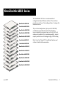
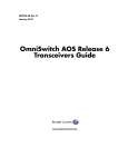
The OmniSwitch 6850 Series is an advanced fixed
configuration family of Ethernet switches. These switches
provide wire rate Layer 2 forwarding and Layer 3 routing with
advanced services.
They are fixed configuration, triple-speed (10/100/1000)
switches that provide increased network performance,
improved application response times, secure the LAN, and
enhance user productivity by maximizing mobility, network
capacity, and services over existing category 5/5E/6 cabling.
PWR
PRI
OK
P48L
6850USB
witch
24
23
OmniS
22
4
25
21
3
24
20
PRODUCT
2
1 LASER
1
21
19
PRODUCT
23
18
CLASS
19
17
1 LASER
CLASS
17
le
24
Conso
16
22
15
14
20
15
13
12
OmniSwitch 6850-24
18
13
11
10
11
9
9
16
8
14
7
6
12
7
5
4
10
5
3
2
3
1
1
BPS
8
PWR
PRI
6
OK
4
U24X
6850-
26
2
USB
witch
OmniS
25
PRODUCT
1 LASER
25
CLASS
26
le
Conso
48
47
46
45
BPS
44
PWR
43
PRI
OmniSwitch 6850-48
42
OK
41
40
24
39
6850witch
Refer to the User Manual CD for additional hardware and
software OmniSwitch documentation.
38
37
USB
OmniS
36
35
34
33
32
31
30
29
28
le
27
Conso
26
25
OmniSwitch 6850-24X
24
23
22
21
20
19
18
17
16
15
14
13
12
11
10
9
8
7
6
5
4
3
2
1
BPS
PWR
PRI
OK
48
6850USB
witch
OmniS
4
3
PRODUCT
2
1 LASER
1
CLASS
le
Conso
24
23
22
21
24
20
19
23
18
PRODUCT
22
17
1 LASER
21
16
CLASS
15
14
13
12
11
10
9
8
7
6
5
4
48
3
47
2
46
1
45
BPS
44
PWR
OmniSwitch 6850-48X
43
PRI
42
41
OK
40
39
24X
38
6850-
26
37
USB
witch
OmniS
36
35
25
34
33
PRODUCT
1 LASER
25
32
31
CLASS
26
30
29
28
le
27
26
Conso
25
24
23
22
21
20
19
18
17
16
15
14
13
OmniSwitch 6850-P24
12
11
10
9
8
7
6
5
4
3
2
1
BPS
PWR
PRI
OK
48X
6850-
50
USB
witch
OmniS
49
PRODUCT
49
1 LASER
CLASS
50
le
Conso
24
23
22
21
20
24
19
23
18
22
17
PRODUCT
1 LASER
21
16
CLASS
15
14
13
12
11
10
9
8
7
6
5
4
3
48
2
47
1
46
45
BPS
44
PWR
43
PRI
42
41
OK
40
P24
39
OmniSwitch 6850-P48
38
685037
USB
witch
OmniS
36
35
34
33
32
31
30
29
28
le
27
Conso
26
25
24
23
22
21
20
19
18
17
OmniSwitch 6850-P24X
16
15
14
13
12
11
10
9
8
7
6
5
4
3
2
1
BPS
PWR
PRI
OK
P48
6850USB
witch
OmniS
4
3
PRODUCT
2
1 LASER
1
CLASS
le
Conso
24
23
22
21
24
20
19
23
18
22
17
21
16
PRODUCT
1 LASER
CLASS
15
14
13
12
11
10
9
8
7
6
5
4
3
48
2
47
1
46
OmniSwitch 6850-P48X
45
BPS
44
PWR
43
PRI
42
OK
41
40
P24X
39
6850-
38
26
USB
witch
37
OmniS
36
25
35
34
PRODUCT
33
1 LASER
25
32
CLASS
31
26
30
29
28
le
27
Conso
26
25
24
23
22
21
20
19
18
17
16
15
14
13
12
11
10
9
8
7
6
5
4
3
2
1
BPS
PWR
PRI
OK
P48X
6850-
50
USB
witch
OmniS
49
PRODUCT
49
50
1 LASER
CLASS
le
Conso
June 2007
OmniSwitch 6850 Series
1
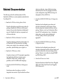
Related Documentation
The following are the titles and descriptions of all the
OmniSwitch 6850 Series user documentation included in the
User Manual CD:
directory architecture, image rollback protections,
authenticated switch access, managing switch files,
system configuration, using SNMP, and using web
management software (WebView).
•
OmniSwitch 6800/6850/9000 Network Configuration
Guide
• OmniSwitch 6850 Series Getting Started Guide
Includes network configuration procedures and
descriptive information on all the major software
features and protocols included in the base software
package. Chapters cover Layer 2 information (Ethernet and VLAN configuration), Layer 3 information
(static routes), security options (authenticated
VLANs), Quality of Service (QoS), and link
aggregation.
Describes the hardware and software procedures for
getting an OmniSwitch 6850 Series switch up and
running. Also provides information on fundamental
aspects of OmniSwitch hardware components and
software architecture.
• OmniSwitch 6850 Series Hardware Users Guide
Complete technical specifications and procedures for
all OmniSwitch 6850 Series hardware, including
chassis, power supplies, fans, combo ports, stacking
procedures, optional backup power supplies, etc.
• OmniSwitch CLI Reference Guide
Complete reference to all CLI commands supported on
the OmniSwitch 6850 Series. Includes syntax
definitions, default values, examples, usage
guidelines, and CLI-to-MIB variable mappings.
• OmniSwitch 6800/6850/9000 Switch Management
Guide
•
OmniSwitch 6800/6850/9000 Advanced Routing
Configuration Guide
Includes network configuration procedures and
descriptive information on all the software features and
protocols included in the advanced routing software
package. Chapters cover multicast routing (DVMRP
and PIM-SM) and OSPF.
• OmniSwitch Transceivers Guide
Includes information on Small Form Factor Pluggable
(SFPs) and 10 Gbps Small Form Factor Pluggables
(XFPs) transceivers.
Includes procedures for readying a switch for
integration into a network. Topics include the software
2
OmniSwitch 6850 Series
June 2007
Installing the Hardware
Items Required
Electrical Requirements
In addition to the materials and components provided in the
OmniSwitch 6850 Series shipment, you must provide the
following items in order to complete this installation:
OmniSwitch 6850 Series switches have the following general
electrical requirements:
• Grounding wrist strap
• Phillips screwdriver
• Serial cable
• Rack mount screws, if applicable
Site Preparation
Environmental Requirements
OmniSwitch 6850 Series switches have the following environmental and airflow requirements:
• The installation site must maintain a temperature
between 0° and 45° Celsius (32° and 113° Fahrenheit)
and not exceed 95 percent maximum humidity (noncondensing) at any time.
• Be sure to allow adequate room for proper air
ventilation and access at the front, back, and sides of
the switch. No clearance is necessary at the top or
bottom of the chassis. Refer to page 6 for minimum
clearance requirements.
June 2007
• Each switch requires one grounded AC power source.
• Grounded AC power source must be 110V for North
American installations (220V international).
• Each supplied AC power cord is approximately 2
meters (6.5 feet) long. Do not use extension cords.
NEBS GR-1089 Compliance Requirements
The following notes and warnings apply to all NEBS
compliant platforms.
Grounding requirements: To ground the equipment properly, connect a Panduit Corporation UL listed Lug, P/N:
LCD8-10AL to the two threaded holes located on the rear of
each chassis and power supply module. All connections should
be made using 8AWG copper conductors.
Use Panduit Corporation, P/N: CT-940CH for crimping. (Each
Module must have its own grounding conductor.)
(GR-1089 requires treatment of ground connections and
painted surfaces as needed during installation.)
Installing the Hardware
3
All surfaces that are used for intentionally grounding the EUT
shall be brought to a bright finish and an anti oxidant solution
must be applied to the surfaces being joined.
Non-conductive coatings (such as lacquer and enamel) must be
removed from threads and other contact surfaces to assure
electrical conductivity.
Weight Considerations
A single OS6850 weighs approximately 14 lbs
(6.24 Kgs). A stack of eight OS6850 switches weighs
approximately 112 lbs (50 Kgs).
(Thread forming screws with paint piercing washers may be
used for this purpose during installation)
Warning. The intra-building interfaces of this platform,
including Gigabit Ethernet, are suitable for connection to
intra-building or unexposed wiring or cabling only with
shielded and grounded cables at both ends. The intra-building
ports of the equipment must not be metallically connected to
interfaces that connect to the OSP or its wiring.
Note. All bare conductors must be coated with an appropriate antioxidant compound before crimp connections are
made. All unplated connectors, braided strap, and bus bars
are to be brought to a bright finish and then coated with an
antioxidant before connecting them.
4
Installing the Hardware
June 2007
Items Included
Unpacking and Initial Setup
Your OmniSwitch 6850 Series switch order includes the
following items:
Unpacking the Chassis
• OmniSwitch 6850 Series chassis
mount flanges may be pre-installed on some orders)
To protect your OmniSwitch chassis and hardware components from electrostatic discharge (ESD) and physical damage,
read all unpacking recommendations and instructions carefully before beginning.
• Power cord (country-specific)
Recommendations
• Rack mount flanges with attachment screws (rack
• Documentation CD containing a complete set of user
guides for the switch and switch software. Refer to
“Related Documentation” on page 2 for a complete list of
included documentation.
Depending on the items ordered for your specific network
requirements, the following optional items may also be
included:
• Unpack your OmniSwitch chassis as close as possible
to the location where it will be installed.
• Depending on your order, Small Form-Factor Plugga-
bles (SFPs), stacking cables and backup power supply
components may be packaged separately. In order to
greatly reduce exposure to electrostatic discharge
(ESD) and physical damage, do not unpack these items
until they are ready to be installed.
• Stacking cables (per order)
• SFPs (per order)
Instructions
1 Carefully cut the tape along the seam at the top of the
• 10-Gigabit XFPs (per order)
box containing the chassis.
• Backup power supply components and cables
2 Lift the box’s top flaps. Remove any smaller boxes or
(per order)
pouches that are enclosed and set them aside.
3 Lift the chassis out of the packaging.
June 2007
Installing the Hardware
5
4 Carefully remove any foam pads and protective plastic
from the switch chassis.
Note. Alcatel-Lucent provides factory-installed blank
cover plates for empty backup power supply or 10-Gigabit expansion module bays. Do not remove these cover
plates unless a backup power supply or expansion module
is to be installed immediately at the corresponding bay.
5 If you are installing multiple switches in a stacked
configuration, repeat steps 1 through 4 for the remaining
switches that will make up the stack.
6 Once all OmniSwitch 6850 Series switches have been
removed from their packaging, continue to “Setting Up
the Switch.”
Setting Up the Switch
Note. Due to their airflow and access requirements,
OmniSwitch 6850 Series switches cannot be wallmounted.
Airflow Considerations
Be sure that your switch is placed in a well-ventilated, staticfree environment. Always allow adequate clearance at the
front, rear, and sides of the switch.
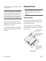
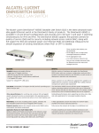
The following diagram shows recommended minimum clearances for adequate chassis airflow and access to components at
the rear of the chassis:
Rear. 5 inches minimum
at rear of chassis.
Sides. 2 inches minimum
at left and right sides for
chassis airflow.
48
47
46
45
44
43
42
41
40
39
38
37
36
35
34
33
32
31
30
29
28
27
26
25
24
23
22
21
20
19
18
17
16
15
14
13
12
11
10
9
8
7
6
5
4
3
2
1
BPS
PWR
PRI
OK
-48
ch
iSwit
6850
USB
Omn
4
3
CT
PRODU
2
LASER
1
1
CLASS
Front. 6 inches minimum
at front of chassis for
cable access and LED
visibility.
Chassis Top View
6
Installing the Hardware
June 2007
Never obstruct the air vents located at the left and right sides
of the chassis.
Note. Clearance is not required at the top and bottom of
the chassis. For detailed chassis airflow diagrams, refer to
the OmniSwitch 6850 Series Hardware Users Guide.
Note. OmniSwitch 6850 Series switches must be placed
“right side up.” Never attempt to operate a switch positioned on its side.
Tabletop Mounting Steps
To install the switch as a tabletop unit, follow the steps below:
Installation Options
There are two ways in which the OmniSwitch 6850 Series
switches can be installed:
• Tabletop installation
• Rack-mount installation
For information on setting up a switch as a tabletop unit, refer
to “Installing the Switch on a Tabletop or Bench.” For information on rack-mounting the switch, refer to
“Rack-Mounting the Switch” on page 8.
Installing the Switch on a Tabletop or
Bench
OmniSwitch 6850 Series switches can be installed freestanding as tabletop units. Place your switch on a stable, flat, and
static-free surface.
June 2007
1 Position the chassis on the table or bench where it is to
be installed.
2 Be sure that adequate clearance has been provided for
chassis airflow and access to the front, back, and sides of
the switch. For recommended clearances, refer to page 6.
Also, be sure that you have placed the chassis within reach
of all required AC power sources.
If you are placing multiple switches in a stacked configuration, carefully stack the remaining switches, one on top
of the other. Up to eight switches may be stacked to form
a single virtual chassis. Be sure to maintain adequate
clearance at the front, rear, left, and right side of all
switches (see page 6). Also, be sure that you have placed
all switches in the stack within reach of required AC
power sources.
Note. If you are installing a single (i.e., standalone)
switch, continue to “Connections and Cabling” on page 11
for additional setup procedures.
Installing the Hardware
7
Rack-Mounting the Switch
Refer to the important guidelines below before installing the
OmniSwitch chassis in a rack.
• It is recommended that two people install the switch in
the rack—one person to hold the chassis and position it
in the rack, and a second person to secure the chassis to
the rack using attachment screws (not supplied).
• Review page 6 for important chassis airflow and access
recommendations before installing.
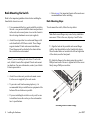
Rack Mounting Steps
To rack-mount the switch, follow the steps below:
Note. Rack-mount flanges may come factory-installed in
some cases. If this is the case, skip steps 1 and 2 below.
• Alcatel-Lucent provides two rack-mount flanges with
each OmniSwitch 6850 Series switch. These flanges
support standard 19-inch rack mount installations.
These flanges must be attached to the chassis before
the switch can be rack mounted.
Note. If you are installing the switch in a 23-inch wide
rack, Alcatel-Lucent offers optional 23-inch rack-mounting hardware. For more information, contact your AlcatelLucent representative.
1 Align the holes in the provided rack-mount flanges
with the four threaded holes in the OmniSwitch chassis.
These threaded holes are located in the left and right sides
of the chassis, near the front panel.
2 Attach the flanges to the chassis using the provided
Phillips-head screws. Be sure to tighten each of the screws
firmly using a Phillips screwdriver.
45
• Alcatel-Lucent does not provide rack-mount screws.
Use the screws supplied by the rack vendor.
46
• To prevent a rack from becoming top heavy, it is
recommended that you install heavier equipment at the
bottom of the rack whenever possible.
le
n so
Co
• If you are installing the switch in a relay rack, be sure
to install and secure the rack as per the rack manufacturer’s specifications.
Attaching a Rack-Mount Flange
8
Installing the Hardware
June 2007
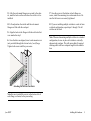
3 After the rack-mount flanges are secured to the chas-
7 Once the screws at the bottom of each flange are
sis, mark the holes on the rack where the switch is to be
installed.
secure, install the remaining two rack-mount screws. Be
sure that all screws are securely tightened.
4 Lift and position the switch until the rack-mount
8 If you are installing multiple switches in a rack to form
flanges are flush with the rack post.
a stacked configuration, repeat steps 1 through 7 for all
switches in the stack.
5 Align the holes in the flanges with the rack holes that
were marked in step 3.
6 Once the holes are aligned, insert a rack-mount screw
(not provided) through the bottom hole of each flange.
Tighten both screws until they are secure.
Note. When rack mounting multiple switches in a stacked
configuration, be sure to place all switches in verticallyadjacent rack positions. This will ensure that all required
stacking cables will have adequate length for the installation.
Attaching the Switch to the Rack
Note. Be sure to install the screws in the bottom hole of
each flange, as shown, before proceeding.
June 2007
Installing the Hardware
9
Installing Combo Port SFPs
OmniSwitch 6850 Series switches offer Gigabit Ethernet
combo ports, located on the front panel. These combo ports
support hot-swappable fiber Small Form-Factor Pluggables
(SFPs). For instructions on installing and removing combo
port SFPs, refer to the instruction card provided with the SFP
product.
Note. Combo port preferences are user-configurable via
the system software. Refer to the “Configuring Ethernet
Ports” chapter in the OmniSwitch 6800/6850/9000
Network Configuration Guide for complete details.
Installing Backup Power Supply
Components
For detailed information on installing backup power supply
components—including the backup power supply, connector
cables, and power cords—refer to the OmniSwitch 6850 Series
Hardware Users Guide.
For information on connecting stacked switches, refer to the
OmniSwitch 6850 Series Hardware Users Guide.
Note. For further details regarding supported SFP and
XFP transceivers, refer to the OmniSwitch Transceivers
Guide.
10
Installing the Hardware
June 2007
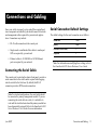
Connections and Cabling
Once your switch is properly set up and all the required hardware components are installed, you should connect all network
and management cables required for your network applications. Connections may include:
Serial Connection Default Settings
The default settings for the serial connection are as follows:
baud rate
9600
• RJ-45 cable connection to the console port
parity
none
• Single mode or multimode fiber cables to combo port
data bits (word size)
8
stop bits
1
SFPs as required by your network
• Ethernet cables to 10/100/1000 or 10/100 Ethernet
ports as required by your network
Note. For information on modifying these settings, refer to
the OmniSwitch 6850 Series Hardware Users Guide.
Connecting the Serial Cable
The console port, located on the chassis front panel, provides a
serial connection to the switch and is required when logging
into the switch for the first time. By default, this RJ-45
connector provides a DTE console connection.
Note. For stacked configurations, the serial cable should
be connected to primary management module. If you are
connecting the serial cable to a stack, it is advisable to
wait until the stack has booted and the primary module has
been dynamically assigned. Refer to the OmniSwitch 6850
Series Hardware Users Guide for more information.
June 2007
Connections and Cabling
11
Booting OmniSwitch 6850
Series Switches
Booting a Standalone Switch
The OmniSwitch 6850 Series switch does not use an on/off
switch. The power cord is the switch’s only connect/disconnect device. The power connector socket is located on the
switch’s rear panel. For more information, refer to the
OmniSwitch 6850 Series Hardware Users Guide.
LED States for a Standalone Switch
BPS
Solid amber, if BPS attached is failed;
off, if no operational BPS is attached;
solid green if an operational BPS is
attached and operating normally.
XFP1
Off (applies to all OmniSwitch 6850
Series switches except for the
OmniSwitch 6850-24X,
OmniSwitch 6850-P24X,
OmniSwitch 6850-48X,
OmniSwitch 6850-P48X, and
OmniSwitch 6850-U24X).
XFP2
Off (applies to all OmniSwitch 6850
Series switches except for the
OmniSwitch 6850-24X,
OmniSwitch 6850-P24X,
OmniSwitch 6850-48X,
OmniSwitch 6850-P48X, and
OmniSwitch 6850-U24X).
Slot Indicator
1–8 (non-blinking), depending on the
slot number value in the boot.slot.cfg
file. See the OmniSwitch 6850 Series
Hardware Users Guide for detailed
information. The default value is 1.
To boot the switch, plug the power cord (provided) into the
power connector socket at the switch’s rear panel. Next, plug
the power cord into an easily-accessible power source, such as
a grounded AC outlet or an Uninterruptible Power Supply
(UPS).
The switch immediately begins the boot process. Allow a few
moments for the switch to boot completely, then verify the
status of all LEDs on the switch’s front panel. A successful
boot for a standalone switch displays the following LED
states:
LED States for a Standalone Switch
12
OK
Solid green
PRI
Solid green
PWR
Solid green
Booting OmniSwitch 6850 Series Switches
June 2007
If any of the LED state differs from the states shown in the
table above, refer to the OmniSwitch 6850 Series Hardware
Users Guide for more information. Contact Alcatel-Lucent
Customer Support if the unexpected LED state persists.
For information on booting stacked configurations and
dynamic slot numbering, refer to the OmniSwitch 6850 Series
Hardware Users Guide.
June 2007
Booting OmniSwitch 6850 Series Switches
13
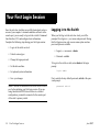
Your First Login Session
Once the switch or stack has successfully booted and you have
accessed your computer’s terminal emulation software via the
console port, you are ready to log in to the switch’s Command
Line Interface (CLI) and configure basic information.
Complete the following steps during your first login session:
Logging in to the Switch
When you first log in to the switch or stack, you will be
prompted for a login (i.e., user) name and password. During
this first login session, only one user name option and one
password option is available:
• Log in to the switch or stack
• Login (i.e., user name)—admin
• Unlock session types
• Password—switch
• Change the login password
• Set the date and time
• Set optional system information
• Save your changes
Note. You must be connected to the switch via the console
port before initiating your first login session. If you are
using OmniSwitch 6850 Series switches in a stacked
configuration, you must be connected to the console port
of the stack’s primary switch.
14
Your First Login Session
To log in to the switch or stack, enter admin at the login
prompt:
login: admin
Next, enter the factory default password, switch, at the password prompt:
password: switch
June 2007
The default welcome banner, which includes information such
as the current software version and system date, displays—
followed by the CLI command prompt:
Welcome to the Alcatel-Lucent OmniSwitch 6850 Series
Software Version 6.1.5.281.R01 Development, March 16, 2007.
Copyright(c), 1994-2007 Alcatel-Lucent All Rights reserved.
OmniSwitch(TM) is a trademark of Alcatel-Lucent registered
in the United States Patent and Trademark Office.
->
More Information on User Accounts. A user account
includes a login name, password, and user privileges.
Privileges determine whether the user has read or write
access to the switch and which commands the user is
authorized to execute.
For detailed information on setting up and modifying user
accounts and user privileges, refer to the “Managing
Switch User Accounts” chapter of your OmniSwitch 6800/
6850/9000 Switch Management Guide.
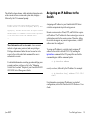
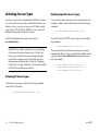
Assigning an IP Address to the
Switch
Assigning an IP address to your OmniSwitch 6850 Series
switch is an important step in the setup process.
Remote sessions such as Telnet, FTP, and WebView require
an IP address. The IP address for these session types serves as
a destination point for the remote session. Therefore, before
the switch can support any remote login sessions, a valid IP
address must be configured.
To assign an IP address to a switch, simply assign an IP
address to the switch’s default VLAN 1 by entering the
ip interface command at the CLI prompt. Be sure that the
command begins with the command syntax:
-> ip interface address
exactly as shown, followed by the IP address. For example:
-> ip interface vlan_1 address 172.2.120.1
vlan 1
For information on assigning IP addresses in a stacked
configuration, refer to the OmniSwitch 6850 Hardware Users
Guide.
June 2007
Your First Login Session
15
Unlocking Session Types
Unlocking Specified Session Types
Security is a key feature on OmniSwitch 6850 Series switches.
As a result, when you access the switch for the first time, you
must use a direct console port connection. All other session
types (Telnet, FTP, WebView, SNMP, etc.) are “locked out”
until they are manually unlocked by the user.
You can also unlock session types on a one-by-one basis. For
example, to unlock Telnet sessions only, enter the following
command:
The CLI command used to unlock session types is
aaa authentication.
To unlock WebView (HTTP) sessions only, enter the following command:
-> aaa authentication telnet local
-> aaa authentication http local
Note. When you unlock session types, you are granting
switch access to non-local sessions (e.g., Telnet). As a
result, users who know the correct user login and password will have remote access to the switch. For more
information on switch security, refer to the “Managing
Switch User Accounts” chapter of your OmniSwitch 6800/
6850/9000 Switch Management Guide.
You cannot specify more than one session type in a single
command line. However, you can still unlock multiple session
types by using the aaa authentication command in succession. For example:
-> aaa authentication http local
-> aaa authentication telnet local
-> aaa authentication ftp local
Unlocking All Session Types
To unlock all session types, enter the following command
syntax at the CLI prompt:
-> aaa authentication default local
16
Your First Login Session
June 2007
Changing the Login Password
Change the login password for admin user sessions by following the steps below:
1 Be sure that you have logged into the switch as user
type admin (see “Logging in to the Switch” on page 14).
2 Enter the keyword password and press Enter.
3 Enter your new password at the prompt (refer to the
All subsequent login sessions—including those through the
console port—will require the new password in order to access
the switch.
User Accounts. The switch allows a maximum of 50 user
accounts in the local user database. For information on
creating additional user types and assigning individual
passwords, refer to the “Managing Switch User Accounts”
chapter of your OmniSwitch 6800/6850/9000 Switch
Management Guide.
note below).
Note. Typically, the password should be a string of nonrepeating characters. The switch’s authentication software
uses the first occurrence of the character series to uniquely
identify the password. For example, the password
engrengr is the same as engr. A better password might be
engr2735.
4 You will be prompted to re-enter the password. Enter
the password a second time.
Note. Be sure to remember or securely record all new
passwords; overriding configured passwords on
OmniSwitch 6850 Series switches is restricted.
New password settings are automatically saved in real time to
the local user database; the user is not required to enter an
additional command in order to save the password information. Also note that new password information is retained
following a reboot.
June 2007
Your First Login Session
17
Setting the System Time Zone
The switch’s default time zone is UTC (also referred to as
Greenwich Mean Time).
If you require a time zone that is specific to your region—or if
you need to enable Daylight Savings Time (DST) on the
switch—you can configure these settings via the
system timezone and system daylight savings time
commands. For example, to set the system clock to run on
Pacific Standard Time, enter the following command:
-> system timezone pst
To enable Daylight Savings Time, enter the following
command:
-> system daylight savings time enable
Many other time zone variables are supported. For detailed
information on configuring a time zone for the switch, refer to
your OmniSwitch 6800/6850/9000 Switch Management Guide.
Setting the Date and Time
Set the current time for the switch by entering system time,
followed by the current time in hh:mm:ss. For example:
-> system time 18:35:00
The switch uses a 24-hour clock; the time value shown in the
above example would set the time to 6:35 PM.
18
Your First Login Session
To set the current date for the switch, enter system date,
followed by the current date in mm/dd/yyyy. For example:
-> system date 06/27/2005
Setting Optional System
Information
This section provides information on configuring optional
system parameters, including:
• the switch’s administrative contact
• a system name
• the switch’s physical location
Specifying an Administrative Contact
An administrative contact is the person or department in
charge of the switch. If a contact is specified, users can easily
find the appropriate network administrator if they have questions or comments about the switch.
To specify an administrative contact, enter system contact,
followed by a text string of up to 254 characters. If you
include spaces between words in the text string, be sure to
enclose the string in quotes (" ").
For example:
-> system contact "JSmith [email protected]"
June 2007
Specifying a System Name
Viewing and Saving Changes
The system name is a simple, user-defined text description for
the switch.
To view your current changes, enter show system at the CLI
prompt.
To specify a system name, enter system name, followed by a
text description of up to 19 characters.
Once you have configured this basic switch information, save
your changes by entering write memory at the CLI command
prompt.
Note. You cannot include spaces between words when
entering a system name.
For example:
-> system name EngSwitch3
Specifying the Switch’s Location
It is recommended that you use a physical labeling system for
locating and identifying your switch(es). Examples include
placing a sticker or placard with a unique identifier (e.g., the
switch’s default IP address) on each chassis.
However, if no labeling system has been implemented or if
you need to determine a switch’s location from a remote site,
entering a system location can be very useful.
To specify a system location, enter system location, followed
by a text description of up to 254 characters. If you include
spaces between words in the text string, be sure to enclose the
string in quotes (" ").
For example:
When the write memory command is entered, changes are
automatically saved to the main configuration file (boot.cfg)
and placed in the /flash/working directory. For more information on the boot.cfg file, refer to page 20.
Note. If the switch reboots following a write memory
command entry, the switch will run from the
/flash/certified directory. As a result, subsequent configuration changes cannot be saved using the write memory
command until the switch is once again running from the
/flash/working directory. See page 22 for important
information on these directories.
This completes the initial configuration process. Your
OmniSwitch 6850 Series switch is now ready for additional
configuration and network operation. Refer to the following
sections for more information on using your switch, as well as
additional built-in features.
For stacked configurations, be sure to refer to the OmniSwitch
6850 Series Hardware Users Guide.
-> system location "NMS Lab--NE Rack"
June 2007
Your First Login Session
19
Files and Directories
Boot and Image Files
boot.cfg File
Although the flash memory on OmniSwitch 6850 Series
switches can contain many file types (e.g., log and snapshot
files), there are four specific file types that provide key switch
and network functions. These files include the boot.cfg file,
boot.params file, boot.slot.cfg file, and image (.img) files.
The boot.cfg file stores your network configuration parameters. When you first boot the switch, no boot.cfg file is
present. This file is automatically generated when you first
issue a write memory command to save your configuration
changes. The file is then automatically placed in the
/flash/working directory.
boot.params File
The boot.params file provides IP address, gateway, and mask
information for the switch. This information is required for
Ethernet connections to the switch.
This file also contains default console port parameters (baud
rate, etc.) and can be modified via the modify boot
parameters CLI command.
In order to be read by the switch, the boot.params file must be
placed in the /flash directory. If the file is deleted for any
reason, a new boot.params file will be automatically generated on the next system boot. However, all user-configured
information, such as IP address, gateway, and mask information, will be lost. Therefore, it is recommended that you keep a
backup copy of this file at all times.
20
Files and Directories
Important. Your switch must be running from the
/flash/working directory in order to save changes to the
boot.cfg file. Refer to “Working and Certified Directories” on page 22 for more information.
Once the configuration parameters stored in the boot.cfg file
are considered tested and reliable, the file can be copied to the
/flash/certified directory and become part of the “last known
good” software for the switch.
If all copies of this file are deleted and a system boot occurs,
your network configuration will be lost. Therefore, it is recommended that you keep a backup copy of this file at all times.
June 2007
Image Files
Image files (those files with .img extensions) contain an
executable code that provides support for the system, Ethernet
ports, and network functions. In other words, they serve as
essential drivers for switch and network operations.
Although these files may be backed up to the root flash directory or any user-defined subdirectory, they must be present in
the /flash/working and /flash/certified directories for the
switch to operate and pass traffic.
If you delete all copies of an image file, you will be required to
contact Alcatel-Lucent Customer Support for replacements.
Therefore, it is recommended that you keep backup copies on
your computer’s hard drive or a locally-accessible server.
June 2007
For a complete list of OmniSwitch 6850 Series image files,
along with their functions, refer to the following table:
K2os.img
Contains the OmniSwitch 6850
Series operating system software.
Kbase.img
Contains base code for the switch.
Krelease.img
Contains release number information
for the system software package.
Keni.img
Provides support for 10/100/1000
and Gigabit Ethernet.
Kadvrout.img
Alcatel-Lucent’s Advanced Routing
software package. Optional.
Ksecu.img
Provides enhanced security features
for the switch, such as Authenticated
VLANs (AVLANs).
K2diag.img
Provides enhanced hardware
diagnostics for the switch.
Files and Directories
21
Working and Certified
Directories
OmniSwitch 6850 Series switches offer flash memory with
8 MB base ROM space and 64 MB extended ROM. This memory is used to store files, including boot and image files, that
are used for switch operations.
The /flash directory contains two subdirectories: /working and
/certified. These directories work together to provide the
image rollback resiliency feature. Image rollback allows the
switch to return to a prior “last known good” version of software in the event of a system software problem.
Working Directory
Working Directory
Intended for: Files that are being configured
and tested. Once these files are considered
valid and reliable, they can be copied to
the Certified directory.
On reload: If the Working and Certified
directories are identical, the switch will
automatically run from software in this
directory. If the two directories are not
identical, you can instruct the switch to run
from the Working directory by issuing the
reload working command.
Saving changes: You can save configuration changes to the Working directory
via the write memory command.
The /flash/working directory is intended for software that is
still being configured for your network. Changes made while
configuring your switch are saved to the boot.cfg file in the
/flash/working directory.
Once the /flash/working directory’s configuration and image
files are road-tested and considered valid and reliable for your
network, they can be copied to the /flash/certified directory.
22
Files and Directories
June 2007
Certified Directory
Certified Directory
Intended for: Reliable, Tested configuration
and image files. The switch will roll back
to this software in the event of a system
software error.
On reload: By default, the switch will use
the software in this directory if there are
any differences between the Working and
Certified directories.
Saving changes: You cannot save configuration changes to the Certified directory.
To save your changes, be sure that your
switch is operating from the Working
directory.
The software in the /flash/certified directory should be treated
as the “gold master” for the switch. When you place configuration and image files in this directory, you are “certifying”
them as tested and reliable. If the switch is running from the
/flash/working directory and experiences a software problem,
it will “roll back” to the last known good software in the
/flash/certified directory on the next reboot.
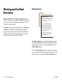
How can I tell which directory the switch
is currently using?
When you first boot the switch, the /flash/working directory is
used; this allows you to save your initial configuration changes
to the boot.cfg file. However, subsequent boots may result in
your switch running from the /flash/certified directory. Therefore, verifying the current running directory is a key step any
time you are configuring or monitoring the switch.
View the switch’s current running directory by entering the
show running-directory command. For example:
-> show running-directory
CONFIGURATION STATUS
Running CMM
:
CMM Mode
:
Current CMM Slot
:
Running configuration
:
Certify/Restore Status
:
SYNCHRONIZATION STATUS
Flash Between CMMs
:
Running Configuration
:
Stacks Reload on Takeover:
Activation)
PRIMARY,
DUAL CMMs,
1,
WORKING,
CERTIFY NEEDED
SYNCHRONIZED,
NOT AVAILABLE,
ALL STACKs (SW
In this example, the switch is using the /flash/working directory. For more information on the show running-directory
command output, refer to the “CMM Commands” chapter in
the OmniSwitch CLI Reference Guide.
June 2007
Files and Directories
23
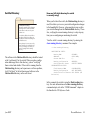
Can I save changes to the Certified directory?
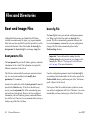
Working and Certified Are Identical
No. The /flash/certified directory is intended to store only
tested, reliable configuration and image files. Configuration
changes must be saved to the boot.cfg file in the
/flash/working directory. Once those changes have been roadtested, the contents of the /flash/working directory can be
copied to the /flash/certified directory via the
copy working certified command.
If the software in the /flash/working and /flash/certified
directories are completely identical, the switch considers the
software in both directories to be equally reliable. In this case,
the switch will run from the /flash/working directory.
Working
Directory
What happens when the switch boots?
During the boot process, the switch compares the contents of
the /flash/working and /flash/certified directories. Based on
this comparison, the switch determines which directory to use
as its running software.
Working and Certified
contents are identical.
boot.cfg
K2base.img
K2release.img
Etc.
Certified
Directory
boot.cfg
K2base.img
K2release.img
Etc.
The switch runs
from Working.
Working
Directory
boot.cfg
K2base.img
K2release.img
Etc.
Certified
Directory
boot.cfg
Hbase.img
Hrelease.img
Etc.
When the switch is running from the /flash/working directory
software, configuration changes can be saved via the
write memory command.
24
Files and Directories
June 2007
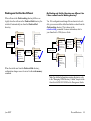
Working and Certified Are Different
My Working and Certified directories are different. Can
I force a reboot from the Working directory?
If the software in the /flash/working directory differs even
slightly from the software in the /flash/certified directory, the
switch will automatically run from the /flash/certified
directory.
Working
Directory
Working and Certified
contents are different.
Working
Directory
revised_boot.cfg
K2base.img
K2release.img
Etc.
Certified
Directory
boot.cfg
K2base.img
K2release.img
Etc.
Yes. If its configuration and image files are known to be reliable, you can override the default and initiate a reboot from the
/flash/working directory. This is done via the
reload working command. For more information, refer to
your OmniSwitch CLI Reference Guide.
boot.cfg
Hbase.img
Hrelease.img
Etc.
The switch runs
from Certified.
Certified
Directory
boot.cfg
K2base.img
K2release.img
Etc.
Working
Directory
Working and Certified
contents are different.
revised_boot.cfg
K2base.img
K2release.img
Etc.
Certified
Directory
boot.cfg
K2base.img
K2release.img
Etc.
The reload working
command overrides
the default; the
switch runs from
Working.
Working
Directory
revised_boot.cfg
K2base.img
K2release.img
Etc.
Certified
Directory
boot.cfg
Hbase.img
Hrelease.img
Etc.
When the switch runs from the /flash/certified directory,
configuration changes cannot be saved via the write memory
command.
Note. For detailed information on using directories, refer
to the “Managing CMM Directory Content” chapter in the
OmniSwitch 6800/6850/9000 Switch Management Guide.
June 2007
Files and Directories
25
Using WebView
The switch can be configured and monitored using WebView,
Alcatel-Lucent’s Web-based device management tool.
WebView software is pre-installed in the switch; you are not
required to load additional software.
Note. Although WebView software is pre-installed, you
must first enable HTTP sessions for your switch before
you can log in. Refer to “Unlocking Session Types” on
page 16 for more information.
Logging In to WebView
Note. Before attempting to establish a WebView session,
be sure that you have first unlocked the HTTP session
type via the aaa authentication command. Otherwise, a
login error will occur. See “Unlocking Session Types” on
page 16 for more information.
To access WebView and log in to a switch:
1 Open any Alcatel-Lucent-tested Web browser.
Browser Compatibility
The following Web browsers are recommended for use with
WebView:
• Internet Explorer 6.0 and later for Windows NT, 2000,
XP, 2003
• Netscape 7.1 for Windows NT, 2000, XP
• Netscape 7.0 for Solaris SunOS 5.8
26
Using WebView
June 2007
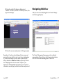
2 Enter the switch’s IP address in the browser’s
“Address” text field (“Location:” for Netscape users). The
login screen displays.
Navigating WebView
After you have successfully logged in, the Chassis Management home page displays.
3 Enter the user name and password at the login prompt.
Remember, if you have already changed the user name and
password for your switch, be sure to use the new information.
If you have not changed your user name or password, the
factory defaults are admin and switch, respectively. Refer to
the “Managing Switch User Accounts” chapter of your
OmniSwitch 6800/6850/9000 Switch Management Guide for
information on modifying the default user name and password.
June 2007
The Chassis Management home page provides a physical
representation of the switch, as well as basic system information. This is the main launching point for WebView.
Using WebView
27
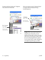
Navigate the application by clicking on the “Configuration
Group” buttons in the left-hand toolbar.
Refine your navigation by selecting “Configuration Options”
for each group from the items displayed in the grey,
horizontal navigation bar.
“Configuration
Options” Toolbar.
(In this case, the option
“Device” has been selected.)
Main “Configuration
Group” Toolbar.
(In this case, the group
“Health” has been selected.)
Site Maps. WebView also provides site maps for each
configuration group. Site maps allow you to view
complete page contents under each feature. By providing
quick, easy access to specific pages, site maps can reduce
time spent searching through the WebView application.
To access site maps, click the “Site Map” link included on
each configuration group Home page, (e.g., Health).
28
Using WebView
June 2007
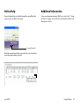
Online Help
Additional Information
General online help is available through the main Help link
located in the top WebView banner.
For more information on using WebView, refer to the “Using
WebView” chapter in the OmniSwitch 6800/6850/9000 Switch
Management Guide.
General Help Link
Detailed, context-based help is provided for each status table
and configuration dialog window.
Context-specific Help
button.(In this case, for the
VLAN Administration table.)
June 2007
Using WebView
29
Troubleshooting
The WebView login screen does not display.
This suggests either a physical or network connection issue.
Try the following options:
• Be sure that you have a good physical Ethernet cable
connection to the switch.
• Be sure your computer has a valid Ethernet connection
and IP address.
• Verify that all required WebView image files are
installed in the current running directory. See page 26 for
more information.
The login screen displays, but the login fails.
This suggests either a user name and password or Authenticated Switch Access error. Try the following options:
• Check that you are using the correct user name and
password. If you have already changed the user name and
password for your switch, be sure to use the new information. If you have not changed the user name and password,
the factory defaults are admin and switch, respectively.
• Be sure that you have “unlocked” HTTP sessions on the
switch. To unlock HTTP sessions, enter the following
command:
-> aaa authentication http local
See page 16 for information on unlocking session types.
30
Using WebView
June 2007