1
4/01ErNs511502
GasFiredCookers
\@'9,-4
lnstallationlnstructionsfor
Aga Gas PowerVent FiredRange
Models:G.C.P.V.(2 Oven)N.G.and L.P'G.
G.E.P.V.(4 Oven)
(.e]
For U.S.and CandianMarkets
ANDTHEUSER
BELEFTVMTHTHEAPPLIANCE
SHOULD
INSTRUCTIONS
NOTE:THESEINSTALLATION
REFERENCE.
FORFUTURE
TO RETAIN
fof
can be made,the siteis inspected
TheGasfiredrangesarc deliveredunassembledBeforeinstallation
codes
local
installation
wiih
conform
to
whefenecessary
andcorrected
.uiLuirltyby i" AifllorisedAga Distributor
or in the absenceof localcodeswith:
ln Canada:
codes
installation
TheCANiCGA-B149
ln U.S.:
The NationalFuelGas CodeANSI2223 1-latestedition
andsafety'
ensurecorrectperformance
on siteby the sameAga Distributorto
Assemblyis undertaken
INSTALLATION
the
It is essentialthatthe baseor hearthon whichthe rangestandsshouldbe leveland strongenoughto support
weightof the rangeweights:
Approximate
G.C.- 406k9(900|b)
l\4odels
G.E.- 585k9(12901b)
materialfor a minimumthicknessof 12mm(1/2)and
Thetop faceof the heanhmustbe of non-combustible
co'nplywithtl-ecunentBuildingRegulaoas and Na onalFlreLaws
aroundthe range
The locationmustalsopfovideadequatespacefor servicingandaif circulation
W A L LT I L I N G
shouldthetiles
lfthe cookeris to standin a fecessor againsta wallwhichis to be tiled,in no circLlmstances
overlapthe rangetop plate.
GAS SUPPLY- U.S.PIPETHREADS
LOCATIONlN THEGASPIPE
lN AN ACCESSIBLE
NOTE:A [4ANUALVALVElllUSTBE INSTALLED
oF GASTo rHE
oNoR SHUTTING
oFTURNING
FoRTHEPURPoSE
Eiienrni io rne nppLrANcE
APPLIANCE.
ALL GASCONTROLSMUSTBE U.S.PIPETHREADS.
Btu/h)
Heatlnput4.4kW(15,000
Maximum
The maximumgas inletpressureat the appliancemustnotexceed1o inchesw.g.for NaturalGas,14 inchesw-g
inches
mustbe5 inchesw g NaturalGasand11
gasinletpressrlrc
at theappliance
forL.P. Gas.TFeminimum
be
obtained
to
wg. L.P.Gasto enablethe correctmanifoldPressure
fromthe gas supplypipingsystemduring
shut-offvalvemustbe disconnected
and its individual
Theappliance
in excessof 1/2 psig(3.skPa).Theappliancemustbe
anv o;essuretestinqofihat svstemat testpressures
duing any pressure
manualshut-offvalve
isoijteafromtne ga1supplypipingsystemby closingits Individual
psi
(3
skPa)
1/2
prcsstre
less
than
equal
to
or
pi6lng
gas-suppli
at
te.t
syiteh
t;atingof the
and purge.Leaktestingofthe applianceshallbe conducted
for soundness
testthe gas installation
on completion
instuctions.
accordingto manufactureis
to ensurethereare no gas leaks
NOTE:Usesoapywatersolutionon newgasconnections
AIRSUPPLY
Kitchenor IntemalAi. SUPPIY
in forcebut in anyeventthe
ii'" ipptilncacan ontybe initilled in a roomwhichmeetsventilaiionregulations
(5
2
2
sin
area
36cm
ventof minimumfreeair
)
roommusthavea permanent
willbe requircd
ventllation
In the eventof an extractorfan beingflttedin the vacinityofthe range,compensatory
flue
conditions
and
efficiency
combustion
influencing
to satisfythe demandsofthe fan wit-hout
ELECTRICAL
1'10/l2oV6oHz,loAN4PFLEX|BLEcoRDANDPLUGPAMLLELTYPE.Theapp|iancewheninsta||ed,m
groundedin accordance
withlocalcodesor, in the absenceof localcodes,w1hthe Na6onalElectrical
ete;11ically
70.
CodesANSI/NFPA
to the
socketmustbe providedwithin6 feetofthe LH sideofthe applianceand easilyaccessible
An etectrical
Do not positionsocketabovethe appliance.
userto disconnect.
WARNING
EleciiicalGroundingInstiuctions
Thisapp|ianceisequippedwitha(three-prong)groundingp|ugforyourprotectionagainstashockhaza
plug
snouldbe pluggeddirbitlyintoa properreceptaaleDo notcut or removethe groundingprongfromthis
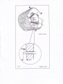
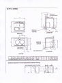
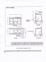
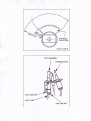
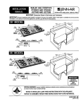
VENTSYSTEM
whichcanreachupto 6
ventpipe50mm(2in)diameter
discharge
is bya fanpowered
Products
of combustion
of 6 x 90' bendsor I metres(29ft)withonebendExitsfromthe
metres(19.5fr)
in lengththrough
a Faximum
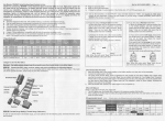
sides,fromtherearcentreor fromtheunderside(Figs.2 & 3).
appliance
canbefromrearL.H.or-R.H.
wallfixingplateby25mm( 1in)Fig.1
theoutsrde
Theventpipeshouldexitthrough
D E S N5 1 1 1 8 9
F I G 1,
DESN511126
rtt
el ffic{lrhl ||!$ru
]
EL
S|l'E
i
gx
!t
o
I
I
f,ffi
tHtt^tsl
al'lr:
ml
\rrfir ntr{N
off xtE||n/rdr*l
L,'1: lSilr$d€l,M
nE|,|n& !3r t'
ffi.TD
Carejts|*
t &€lrUrids ldar & *xs{ra$hn
vArft !*hr&fig donlr6b. Wdng r.rq$
rawF ]rrpr.fllr qrd d!ng4|qf cp!|q!rj
\is|ly frsrnl {rr'ldrrt als $dr6s.
{3i
l-*\o.
E
I
i
n
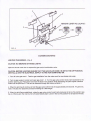
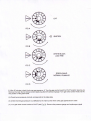
TERMINALPOSITION
'1.The rangemustbe installedso thattheventterminalis exposedto the externalair andterminal
clearancecomDlvwith:
In l.r.s.:The NationalFuelGas CodesANSI22231 latesteditionSection7.7
installation
code.
In Canada:CAN/CGA-8149
2. Termination
shouldbe on a clearexpanseofwall,the terminalbeingpreferablynotlessthan
355mm(14in)awayfroma corner,recessof projection'1.5"frominsideto outsidefaceof
3. A holemustbe cutthroughan outsidewallwiththe holefalling
Openingsin thewallsbehindor on the floorobelowthe appliancemustbe sealedusingthe closureplateand
sealantprovided.
DONOTinstalltheterminaiunderthe followingconditions:
(a)Wthin 300mm( 12in)measuredvedicallyfromthe bottomof an openablewindow,air ventor any
other ventilating
opening.
(b)\Mthin300mm(12in)aboveadjacentgroundlevel.
(c)Wthin 600mm(24in)ofanysurfacefacingthe terminal.
beloweavesor balcony
(d)Wthin355mm(14in)(U.S.)or 300mm(12in)(Canada)
guard(supplied)
installedovertheterminalto prevent
Theterminalmustbe protectedby the terminalprotective
(See
unauthofised
contactwiththe hotteminal surfaces.
E4L1).
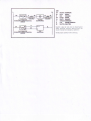
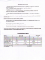
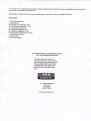
TechnicalSpecification
GCandGE
L.P.G
NaturalGas
rG
e Model
ain BurnerInjecto.
tir
PilotBurner
Iniector
t,-
GasValve
Combination
BvpassScrew
sas BurnerPrcssure
:ombinationGasValve
Piiot
s.t.T.EUROSTT
JOHNSONS
t-il
GCPV12ovElrtsl
f*l]--';o,*o*o,
qarsEo
lrDsWHEN
I i!
I
-T
'r 4Se#"1r'
I
,i
ti
I
rrtlr4tN,|
I
I
tF=:
I
I
Bl
|
I
I
|
I|
t4-:il
|
I
L-_
I
|lrilLlh=
H
l'
l" Hil
- T l|
f
lt
r-,---J
l
t--
-
lF
tLI&::L=FJ
+t l I
'Yr'
I
.,-N
)n-,1*
*1r1e-----*
v#i?#..'-"-
Tl
---J
IINT PIPE
V
,, / ./,/ / / / ,/ ,1"// ,/ ,/ ,/ ,/j/ / / , _*
^'cg::='t-Uil
I| l"
/\
| I
P,]
//'="'\'l
?.
I
\t
I// ,
t
urlsi=ffilbr
vEr.rT
PrPE
ll
\
6l l{,
j|l' )lW
I
\"-// \=d/
II l"
Z
I
"l| V , t l.
|
I
I
tr::::
=::!#1--Vl----l' (/ |
--*
\DOoh'N .;.
|I
OvEr,l
f,
'1.1,/.
oPEN
PosrTroN
- - ; - { I/
t
""--1+B
.ir
Eq
lt, I
I
II
r\tfl,
Llt --- i--!l',,i tI
T./lT----l--Tl
:+
i
I
r11i,/
x{ --1v ,IE-
| 4,,HVll
\//
").,
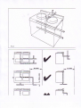
Llt. stDEvEw
Fno$rv|gw
w
/,2GASCONt{EgflON
n H.
+S
t*-
R'K SDEVIIW
PtAtrluEw
c
mm 987 967 851
l''t