1
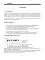
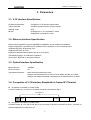
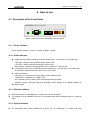
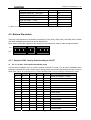
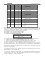
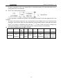
RCMS2101-30-FV35
RCMS2301-30-FV35
RCMS2501-30-FV35
Standalone, Fiber Optic
Ethernet Multiplexer
User Manual
Raisecom Technology Co., Ltd.
(10/2005)
Raisecom Technology Co., Ltd
1. Cautions
Please read the following notices carefully before installing and using the
device, Raisecom does not respond to any loss that caused by violating
safety notice.
RCMS2X01-30-FV35 provides two types of power supply: AC and DC. When
using DC power supply, please plug the power supply connectors
according to this mannual strictly and avoid contrary connecting.
RCMS2X01-30-FV35 is integrated device that has precise elements, please
avoid violent shakes and impacts, and do not disassemble or maintain the
device yourself. If it is required, please do it under the guide of our
technical staff following in the steps of anti static. Please contact us if there
is any need.
There must be grounding protection for the sake of safety; do not
disassemble the device yourself, we regard it as you waiver your rights of
repair guarantee.
1
Raisecom Technology Co., Ltd
Contents
1.
Cautions ............................................................................................................................................1
2.
Overview ...........................................................................................................................................3
2.1.
2.2.
2.3.
2.4.
3.
Parameters........................................................................................................................................5
3.1.
3.2.
3.3.
3.4.
3.5.
3.6.
4.
Introduction ................................................................................................................................3
Main Features ............................................................................................................................3
Model Number Description.........................................................................................................3
Equipment Structure...................................................................................................................4
V.35 Interface Specification ........................................................................................................5
Ethernet Interface Specification .................................................................................................5
Optical Interface Specification ....................................................................................................5
Occupation of V.35 Interface Bandwidth in Framed E1 Timeslot................................................5
Power Supply .............................................................................................................................6
Ambience ...................................................................................................................................6
How to use ........................................................................................................................................7
4.1. Description of the Front Panel....................................................................................................7
4.1.1.
Power indicator ...................................................................................................................7
4.1.2.
Alarm indicator ....................................................................................................................7
4.1.3.
Ethernet interface................................................................................................................7
4.1.4.
Optical Interface..................................................................................................................7
4.2. Description of the Rear Panel ....................................................................................................8
4.2.1.
Power Socket......................................................................................................................8
4.2.2.
V.35 (DCE) Interface ...........................................................................................................8
4.3. Bottom Dip-switch ......................................................................................................................9
4.3.1.
Setup for SW1: factory default setting is all OFF ................................................................9
4.3.2.
The setup for SW2: factory default setting all OFF ...........................................................11
4.3.3.
The setup for SW3: factory default setting all OFF ...........................................................12
5.
Installation and test .........................................................................................................................14
5.1. Inspect after Opening...............................................................................................................14
5.2. Preparation before Installation .................................................................................................14
5.3. Installation ................................................................................................................................14
5.3.1.
Connecting the Cables......................................................................................................14
5.3.2.
Applying the Power Supply ...............................................................................................14
6.
Troubleshooting...............................................................................................................................15
7.
Appendix A Introduction of Cable Making........................................................................................16
A.1 V.35 Cable Making .......................................................................................................................16
A.2 Ethernet Cable Making .................................................................................................................16
2
Raisecom Technology Co., Ltd
2. Overview
2.1. Introduction
RCMS2101-30-FV35, RCMS2301-30-FV35, and RCMS2501-30-FV35 series Ethernet multiplexers are
ideal optical fiber transmission devices for point-to-point networks, medium-sized and small capacity
networks, such as wireless communication base stations, private communication networks and
switching networks. These devices provide one N*64Kbps V.35 (N≤32) and one 100Mbps wire speed
auto-negotiation Ethernet ports. They are also remotely visible and controllable through Raisecom
NView iEMS network management platform.
2.2. Main Features
z
z
z
z
z
z
z
z
Adopt extra-large scale ASIC chip that has low power consumption and high dependability.
Full alarm indication. Local and remote alarm can be displayed simultaneously.
Provide loop-back test at V.35 tributary for easy maintenance.
Provide one 10/100Mbps auto-negotiation Ethernet port with 100M transmission bandwidth.
Support Ethernet port auto-negotiation and forced status.
Support maximum Ethernet data frame size up to 1916 bytes
Support Ethernet full duplex IEEE802.3x and half duplex flow control of backpressure.
RCMS2X01-30-FV35 series multiplexer supports remote control and management.
2.3. Model Number Description
Example:
RC MS 2 1 01 – 30-FV35 / AC
AC power supply
1 V.35 port
1 Ethernet port
Standalone, dual-strand fiber
Switch on layer 2
Multi-service device
Company codename (Raisecom)
Note: Standalone dual-strand fiber Ethernet multiplexer RCMS2101-30-FV35 shall work in pairs, or
work with RCMS2201-30 modular multiplexer.
Standalone RCMS2301-30-FV35 and RCMS2501-30-FV35 single strand fiber Ethernet multiplexer shall
be deployed in pairs. One RCMS2301-30-FV35 must work with one RCMS2501-30-FV35.
RCMS2501-30-FV35 can work in pairs with RCMS2401-30.
3
Raisecom Technology Co., Ltd
2.4. Equipment Structure
Compact desktop design with dimension: 142mm (W) * 38mm * (H)* 178mm (D)
4
Raisecom Technology Co., Ltd
3. Parameters
3.1. V.35 Interface Specification
Physical characteristic:
Type of interface:
Working mode:
Bit rate:
Compliant to V.35 interface specification
ISO2593 female connector (34-pin female)
DCE
N*64Kbps (N=1~31) at framed E1 mode
2048Kbps at unframed E1 mode
3.2. Ethernet Interface Specification
Ethernet auto-negotiation and auto-MDI/MDIX capabilities can be enabled and disabled
Supports IEEE 802.3 and IEEE 802.3u standard, auto-negotiation or forced working mode
Supports IEEE 802.1d Spanning Tree
Supports IEEE 802.1q VLAN
Supports oversized Ethernet data frame up to 1916 bytes
Transmission speed: 10/100M auto negotiation
Flow control: IEEE802.3x and back pressure
3.3. Optical Interface Specification
Named bit rate:
Fiber connector:
Transmission distance:
150Mbps
SC
Multi-mode dual-strand M=0~2km
Single mode dual-strand S1=0~25km, S2=10~60km, and S3=15~120km
Single mode single strand dual-wavelength S1=0~25km and S2=10~50km
3.4. Occupation of V.35 Interface Bandwidth in Framed E1 Timeslot
z Occupation of timeslot in PCM31 mode
In PCM31 mode, N ≤ 31, Slot 0 is occupied. N shall be counted from Slot 1.
V.35 BANWIDTH
TS[0]
TS[1]
……
TS[N]
……
TS[31]
z Occupation of timeslot in PCM30 mode
In PCM30 mode, N ≤ 30, Slot 0 and Slot 16 are occupied. N shall be counted form Slot 1, and Slot 16
shall be skipped if N is larger than 16.
5
Raisecom Technology Co., Ltd
V.35 BANWIDTH
TS[0]
TS[1]
……
TS[16]
……
3.5. Power Supply
Power supply voltage:
Power consumption:
DC -48V, tolerance range -36V ~ -72V
AC 220V, tolerance range 165V ~ 265V
≤ 5W when full loaded
3.6. Ambience
Working temperature:
Relative humidity:
0 ~ 45℃
≤ 90% (25℃)
6
TS[N+1]
……
TS[31]
Raisecom Technology Co., Ltd
4. How to use
4.1. Description of the Front Panel
RAISECOM
RCMS2101-30-FV35 SERIES
LNK
ACT
TX
RX
LOS LOF ERR
V35AL
L
R
PWR
100M
ETH
FDX
Sketch of the front panel for RCMS2X01-30-FV35 series
4.1.1. Power indicator
Power indicator (Green): If power is in good condition, it is ON
4.1.2. Alarm indicator
z
Optical interface alarm (including local and remote sites: L for local site, R for remote site)
LOS (red): If losing receiving optical signal, alarm is ON.
LOF (red): If losing receiving optical frame, alarm is ON.
ERR (yellow): If optical receiving signal bit error exceeds 10-6, alarm is ON.
z
V.35 tributary alarm (red): (including local and remote sites: L for local site, R for remote site)
The indicator will be ON if there is AIS, LOF, or CRC alarm
z
Ethernet indicator:
LNK (green): If connection is normal, alarm is ON. Otherwise OFF
100M (green): 100Mbps: ON; 10Mbps: OFF
ACT indicator (green): flashing when transmitting/receiving signals
FDX/COL (green): ON when working at full duplex mode; flashing when collision happens at
half duplex mode.
4.1.3. Ethernet interface
z
z
Ethernet interface is 10/100Mbps auto sensing and can be configured.
It is capable of auto MDI/MDIX and can be connected with either straight-through or crossover
cable.
4.1.4. Optical Interface
z
For dual-strand fiber model, RCMS2101-30-FV35, the TX wavelength is 1310nm and fiber
7
Raisecom Technology Co., Ltd
z
connector type is DSC/PC. TX stands for optical output, RX for optical input.
For single strand fiber model, RCMS2301-30-FV35 and RCMS2501-30-FV35, the TX wavelength of
RCMS2301-30-FV35 is 1310nm, and the TX wavelength of RCMS2501-30-FV35 is 1550nm. The
fiber connector type is SC/PC.
4.2. Description of the Rear Panel
DCE
Sketch of rear panel of RCMS2X01-30-FV35 series
4.2.1. Power Socket
When using AC power supply, 220V standard 3-phase power socket.
When using DC power supply, -48V power socket. The left pin is connected with -48V, right pin 0V, and
middle pin for protecting ground.
4.2.2. V.35 (DCE) Interface
V.35 interface adopts V.35/ISO2593: DCE Connector Face,
34-pin female connector. It can be connected with standard DTE
cable. The interface definition is as follows:
Name
I/O
Pin Number
Chassis Ground — CGND
-
A
Signal Ground — GND
-
B
Receive Data (A) — RD(A)
O
R
Receive Data (B) — RD(B)
O
T
Receive Timing (A) — RCK(A)
O
V
Receive Timing (B) — RCK(B)
O
X
Send Data (A) — TD(A)
I
P
Send Data (B) — TD(B)
I
S
Send Timing (A) — TCK(A)
O
Y
Send Timing (B) — TCK(B)
O
AA
8
Raisecom Technology Co., Ltd
Terminal Timing (A) — SCTE(A)
I
U
Terminal Timing (B) — SCTE(B)
I
W
Request to Send — RTS
I
C
Clear to Send — CTS
O
D
Data Set Ready — DSR
O
E
Data Carrier Detect — DCD
O
F
Data Terminal Ready — DTR
I
H
I—Input; O—Output
4.3. Bottom Dip-switch
There are 3 dip-switches on the bottom of equipment, SW1 (8-bit), SW2 (4-bit), and SW3 (8-bit). Please
use small flat-blade screw-driver to set the dip-switches.
Note: Please reboot the equipment after setting the dip-switches in order to make changes effective.
ON
OFF
12345678
1234
12345678
4.3.1. Setup for SW1: factory default setting is all OFF
z The 1st~5th bits: V.35 interface bandwidth setup
V.35 bit rate is N*64kbps (N=1~31) when working at framed E1 mode; V.35 bit rate is 2048kbps when
working at unframed E1 mode. These 5 bits of the dip-switch are actually representing the binary code of
the N value. When N is configured to 0, RC801/803/805-30B-FV35 is working at unframed E1 mode.
1st bit
2nd bit
3rd bit
4th bit
5th bit
Bandwidth (bit/s)
0
0
0
0
0
2048K (unframed E1 mode)
0
0
0
0
1
1×64K=64K (minimum bandwidth)
0
0
0
1
0
2×64K=128K
0
0
0
1
1
3×64K=192K
0
0
1
0
0
4×64K=256K
0
0
1
0
1
5×64K=320K
0
0
1
1
0
6×64K=384K
0
0
1
1
1
7×64K=448K
0
1
0
0
0
8×64K=512K
0
1
0
0
1
9×64K=576K
0
1
0
1
0
10×64K=640K
0
1
0
1
1
11×64K=704K
0
1
1
0
0
12×64K=768K
0
1
1
0
1
13×64K=832K
0
1
1
1
0
14×64K=896K
9
Raisecom Technology Co., Ltd
0
1
1
1
1
15×64K=960K
1
0
0
0
0
16×64K=1024K
1
0
0
0
1
17×64K=1088K
1
0
0
1
0
18×64K=1152K
1
0
0
1
1
19×64K=1216K
1
0
1
0
0
20×64K=1280K
1
0
1
0
1
21×64K=1344K
1
0
1
1
0
22×64K=1408K
1
0
1
1
1
23×64K=1472K
1
1
0
0
0
24×64K=1536K
1
1
0
0
1
25×64K=1600K
1
1
0
1
0
26×64K=1664K
1
1
0
1
1
27×64K=1728K
1
1
1
0
0
28×64K=1792K
1
1
1
0
1
29×64K=1856K
1
1
1
1
0
30×64K=1920K (Max bandwidth
1)
1
1
1
1
1
31×64K=1984K (Max bandwidth
2)
In the above table, ‘1’ stands for OFF status of the switch, and ‘0’ stands for ON status. For example, the
binary code corresponding to 384kbps bandwidth is ‘00110’. Then, the switches shall be set to ‘ON, ON,
OFF, OFF, ON’. When doing this, users are advised to note down the binary code corresponding to the
required bandwidth, then refer to the above table for switch status.
‘Max bandwidth 1’ is the maximum bandwidth in PCM30.
‘Max bandwidth 2’ is the maximum bandwidth in PCM31.
z
The 6th bit: V.35 bandwidth control option
6th bit
Bandwidth Control Option
OFF
Master Control
ON
Slave Control
The following conditions shall be satisfied in order to realize the remote bandwidth control function.
1. RCMS2X01-30-FV35 series equipments are deployed point to point, and in pairs.
2. There is no PCM equipment (i.e. DXC, MUX) that takes up the No. 0 timeslot in the link.
3. Neither of the equipment at both sides shall be set to transparent mode (N is not 0).
When all the conditions are met, user can set Master Control at one site and Slave Control at the other
site. The first 5 bits switches can be set to all OFF. After the link is established, the actual bandwidth at
Slave Control site is the same as the Master Control site. Please note that neither of the both sites can
be set to unframed mode (N=0).
This bit switch has nothing to do with the timing resource. Users can either set Master Control at the
Master Clock site, or at the Slave Clock site.
If any of the three conditions cannot be met, then both modems shall be set to Master Control and the
first 5 bits will be used to configure the actual bandwidth. Please note that when N=0, the equipment is
working at unframed mode and this bit switch is invalid.
10
Raisecom Technology Co., Ltd
z
The 7th and 8th bits: clock mode option
7th bit
8th bit
Timing Resource Option
OFF
OFF
Master Clock (Internal)
OFF
ON
V.35 Terminal Clock
ON
OFF
Vacant
ON
ON
Slave Clock (follow the link clock)
Users are advised to select the most suitable timing resource. When configuring clock modes, V.35 DTE
interface on Routers shall also be configured. Both TX and RX clock shall be External Clock mode at
V.35 interface that connected with Master/Slave Clock equipment. The TX Clock shall be Internal Clock
mode and RX Clock shall be External Clock mode at the V.35 interface that connected with Terminal
Clock equipment.
z
The factory default settings of SW1: All OFF
Switch
1st bit
2nd bit
3rd bit
4th bit
5th bit
6th bit
7th bit
8th bit
Default
OFF
OFF
OFF
OFF
OFF
OFF
OFF
OFF
N=31,V.35 bandwidth 1984K
Details
Bandwidth
Master
Control
Master Clock
Mode
4.3.2. The setup for SW2: factory default setting all OFF
z
z
z
1st bit
2nd bit
3rd bit
4th bit
Definition
TX CLK
phase
RX CLK
phase
PCM30/31
Option
CRC
function
option
ON
Negative
Negative
PCM30
Disable
OFF
Positive
Positive
PCM31
Enable
Since the relationships between V.35 data and clock phase are different on different brand Routers,
TX CLK and RX CLK phase options are used to solve the problem.
TX CLK positive: TD signal will be sampled at the falling edge of TCK clock signal
TX CLK negative: TD signal will be sampled at the rising edge of TCK clock signal
RX CLK positive: RD signal will be sampled at the falling edge of RCK clock signal
RX CLK negative: RD signal will be sampled at the rising edge of RCK clock signal
PCM30/31 option. When other equipment (i.e. DXC, MUX) in the link requires the frame format to
be PCM30, the modem shall be configured to PCM30 (N≤30); when requires the frame format to be
PCM31, the modem shall be configure to PCM31 (N≤31). The local and remote sites shall have the
same configuration.
CRC option. Disable/Enable the CRC function according to the link requirement. The local and
remote sites shall have the same configuration.
11
Raisecom Technology Co., Ltd
4.3.3. The setup for SW3: factory default setting all OFF
z
z
z
z
z
z
z
The 1st bit: Ethernet auto-negotiation capability enable/disable
When this bit is switched to off, auto-negotiation capability is enabled.
When this bit is switched to on, auto-negotiation capability is disabled. The working data rate and
duplex mode will be determined by the 2nd and 3rd bits of SW3.
The 2nd bit: Ethernet port data rate
When this bit is switched to off, the data rate is 100M; when switched to on, data rate is 10M.
If the 1st bit of SW3 is off, the 2nd bit is invalid.
If the 1st bit of SW3 is on, the 2nd bit indicates the actual data rate.
The 3rd bit: Ethernet duplex
When this bit is switched to off, the equipment is at full duplex mode; when switched to on, it is at
half duplex mode.
If the 1st bit of SW3 is off, the 3rd bit indicates the actual duplex mode when Ethernet auto
negotiation fails.
If the 1st bit of SW3 is on, the 3rd bit indicates the actual duplex mode.
The 4th bit: vacant. (it is suggested to be switched off)
The 5th bit: Fault-pass-through
The fault-pass-through capability is designed for users who have particular requirements. If this
function is enabled, when there is a fault or the remote Ethernet link is disconnected, the local
Ethernet port will be shut down automatically; when the fault disappeared and remote Ethernet link
is recovered, the local Ethernet port will recover automatically. If the function is disabled, the
Ethernet and V.35 port will always work.
This function is usually used to notify the switch that a link is not proper, when constructing IEEE
802.1d Spanning Tree error tolerance network.
The 6th bit: Ethernet auto-MDI/MDIX function
When this bit is switched to off, auto-MDI/MDIX function is enabled. The Ethernet port can be
connected using either straight-through or crossover cable.
When this bit is switched to on, auto-MDI/MDIX function is disabled. Straight-through cable shall be
used to connect with switch; and crossover cable shall be used to connect with network interface
card.
The 7th bit: remote loop-back function
Remote loop-back is performed at the optical interface on remote equipment to test and diagnose the
optical link. In order to perform the remote loop-back at optical interface, 2 conditions must be satisfied.
1. RCMS2X01-30-FV35 multiplexers work point to point, and in pairs (or RCMS2201-30 series
Ethernet multiplexer at the remote site).
2. The test can only be performed on the ‘Master Clock’ and ‘Terminal Clock’ equipment.
As the above figure, the local equipment is set to Master Clock or Terminal Clock mode. The 7th bit
12
Raisecom Technology Co., Ltd
z
of SW3 is switched to ON. If the optical fiber is connected properly, the loop-back status can be
viewed at the port of local Router.
The 8th bit: Local loop-back function
Local Loop-back is performed at local V.35 interface and used for test and diagnosis the V.35
interface.
The local V.35 interface loop-back can only performed on the ‘Master Clock’ and ‘Terminal Clock’
equipment. As the above figure, the local equipment is set to Master Clock or Terminal Clock mode.
The 8th bit of SW3 is switched to ON, and the 1st ~ 5th bits of SW1 are set to configure the
customized bandwidth. The loop-back status can be viewed at the port of local Router.
z
The factory default setup for SW3 is all OFF
Switch
1st bit
2nd
bit
3rd bit
4th bit
5th bit
6th bit
7th bit
8th bit
Status
OFF
OFF
OFF
OFF
OFF
OFF
OFF
OFF
Definition
Auto
negotiation
100M
Full
duplex
Vacant
FPT
disabled
Auto
MDI/MDIX
Remote
loop-back
disabled
Local
loop-back
disabled
13
Raisecom Technology Co., Ltd
5. Installation and test
5.1. Inspect after Opening
Please first check if the models and part numbers are in consistence, and also check if the
equipments are damaged.
5.2. Preparation before Installation
z
z
z
z
z
Carefully read this manual
Prepare all kinds of the cable. Ensure that they are not short-circuited. Refer to Appendix A for cable
making.
Ensure the voltage of power supply is in the tolerance range, the chassis is well connected with the
ground.
Prepare the BERT and optical power meter for test of line quality.
Place the equipment at stable and secure environment. Pay attention to the requirements of the
ambience.
5.3. Installation
5.3.1. Connecting the Cables
z
V.35 Interface
This interface is not hot-swappable. Please connect it properly before applying the power supply.
z
Ethernet Interface
Connect with Cat. 5 or hyper Cat. 5 twisted-pair cables. Either straight-through or crossover cable is
OK.
z
Fiber connector
Plug the tail fiber into the fiber socket to the end.
5.3.2. Applying the Power Supply
The power supply shall be applied after the previous operation.
If using DC -48V power supply, please first connect “ground” cable with protecting ground. “0V” pin
shall be connected with high potential cable, “-48V’ pin shall be connected with low potential cable.
Ensure there is no short circuit.
If using AC 220V power supply, please use the power cable supplied along with equipment.
After applying the power supply, PWR indicator shall be on.
14
Raisecom Technology Co., Ltd
6. Troubleshooting
If you have any problems during installation and usage, try to solve them by the following proposals. If
the problem persists, please contact distributors for technical support.
These following explanations and solutions of alarm for optical port and LOS alarm of V.35 tributary aim
at alarm of local end. Please handle it at remote end if alarm occurs at remote end.
z
z
z
z
z
z
z
Green PWR indicator is OFF
Answer: power supply faults. Please check whether power is properly supplied and –48V power
cord does not be connected reversely.
Local V.35 tributary alarm indicator (LV35AL) is on
Answer: It is possible that there is uplink alarm (AIS), loss of frame (LOF), or CRC alarm appearing
on the modem. It indicates that the signal received is abnormal. Please check the link quality and
interface parameter at the remote site.
Remote V.35 tributary alarm indicator (RV35AL) is on
Answer: This indicates there is V.35 receiving alarm at the remote site. The signal is sent by
RCMS2X01-30-FV35 equipment.
Optical Interface LLOS (RLOS) is ON
Answer: Receiving signal at optical interface is lost. Please check if the optical input (RX) is
connected, or reversely connected. Users can use the optical power meter to test the receiving
optical power to check if it is above the threshold of optical receiving sensitivity.
Optical Interface LLOF (RLOF) is ON
Answer: Optical receiving signal is loss of frame. Optical signals are receiving but the optical power
may be around the threshold. Please check the receiving optical power. If connects modem of
different brand name at optical interface, there also may be LLOF alarm.
Optical Interface LERR (RERR) is ON
Answer: When flashing, the bit error rate of optical signal is above 10-3. Please check if the optical
interface is connected properly, or the receiving optical power, and also ensure there is no sharp
turn of the optical fiber. When steady on, the bit error rate of optical signal is above 10-6. This alarm
may be appearing just after applying the power supply, which is normal phenomenon, and it shall be
off in 10 seconds. If the indicator is steady on during operation, please check if the optical interface
is connected properly and the receiving optical power.
Severe packet loss of DTE equipment
Answer: The possible reasons for severe packet loss are:
1. Incorrect clock mode setup
2. Check V.35 interface status of the Router, if there are data errors on input and output, then it
indicates that TX CLKand RX CLK phase relationship need to be adjusted. This problem can be
located by performing local V.35 interface loop-back test.
15
Raisecom Technology Co., Ltd
7. Appendix A Introduction of Cable Making
A.1 V.35 Cable Making
V.35 interface is compliant to V.35/ISO2593: DCE Connector Face – 34-pin Female connector. It can be
connected with standard DTE cable. Please refer to Part 3.2.2 for wire sequence.
A.2 Ethernet Cable Making
Use Cat.5 twisted pair to connect the equipment. Please note the twisted pair is less than 100 meters.
The 1st PIN
The 8th PIN
Either straight-through or crossover cable can be used.
RJ45 wire sequence is as following:
Pin
number
Definition
1
2
3
4
5
6
7
8
TX+
TX-
RX+
Not Used
Not Used
RX-
Not Used
Not Used
The pin definition of straight-through twisted-pair cable
Pin 1
Pin 1
Pin 2
Pin 2
Pin 3
Pin 3
Pin 6
Pin 6
The pin definition of crossover twisted-pair cable
Pin 1
Pin 1
Pin 2
Pin 2
Pin 3
Pin 3
Pin 6
Pin 6
Please note that Pin 1 and 2 shall be in one pair, and so Pin 3 and 6.
16
Raisecom Technology Co., Ltd
@2005 Raisecom Technology Co., Ltd.
All trademarks are the property of their respective owners.
Technical information may be subject to change without prior notification.
17