1
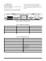
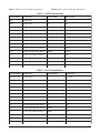
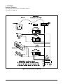
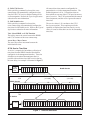
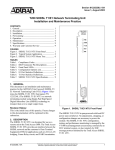
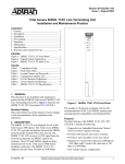
Section 61225101L1-5B
Issue 2, December 2002
Express 6530 SHDSL NxNTU
Installation and Maintenance
CONTENTS
1. GENERAL ..................................................................... 1
2. CONNECTIONS ........................................................... 4
3. OPTIONING .................................................................. 7
4. SPECIFICATIONS ...................................................... 18
5. WARRANTY AND CUSTOMER SERVICE ............ 19
FIGURES
Figure 1.
Figure 2.
Figure 3.
Figure 4.
Figure 5.
Figure 6.
Figure 7.
Figure 8.
Figure 9.
Figure 10.
Figure 11.
Figure 12.
Figure 13.
Figure 14.
Figure 15.
Figure 16.
Figure 17.
Figure 18.
Figure 19.
Figure 20.
Figure 21.
Figure 22.
TABLES
Table 1.
Table 2.
Table 3.
Table 4.
Table 5.
Table 6.
Table 7.
Table 8.
Table 9.
Table 10.
SHDSL
Express
6530
Express 6530 SHDSL NxNTU ...................... 1
Express 6530 Functional Overview ............... 2
Express 6530 Back Panel ................................ 4
Express 6530 Strap Map ................................. 7
Express 6530 Menu Tree ................................. 8
Cross-Connect Map ......................................... 9
Time Slot Allocation ..................................... 10
Framed Full E1 Service ................................. 11
Unframed Full E1 Service ............................. 11
Full Nx64k 2 Mbps Service .......................... 12
Back-to-Back NTU Operation ...................... 12
Local Dual Sided Loopback ......................... 13
Remote Dual Sided Loopback ...................... 13
Local Customer Transparent Loopback ........ 14
Remote Customer Transparent Loopback .... 14
Local Customer Nontransparent Loopback .. 14
Remote Customer Nontransparent
Loopback ....................................................... 14
Local Network Transparent Loopback ......... 14
Remote Network Transparent Loopback ...... 14
Local Network Nontransparent Loopback .... 14
Remote Network Nontransparent
Loopback ....................................................... 14
CRC-4 Detection/Generation ........................ 16
LED Descriptions ............................................ 2
Front Panel Pushbuttons .................................. 3
SHDSL Pin Connections ................................. 4
G.703 Pin Connections .................................... 4
V.28 Pin Connections ...................................... 5
X.21 Pin Connections ...................................... 5
V.35 Pin Connections ...................................... 6
V.36 Pin Connections ...................................... 6
Loopback Overview ...................................... 15
Express 6530 SHDSL NxNTU
Specifications ................................................ 18
1. GENERAL
This practice contains installation and maintenance
information for the Express 6530 SHDSL NxNTU,
P/N 1225101L1. The unit is illustrated in Figure 1.
The ADTRAN Express 6530 is a network terminating
unit using Single-Pair High Speed Digital Subscriber
61225101L1-5B
PORT SELECT
LOCAL LOOP/
ERR INJ
REMOTE LOOP
BERT
LLOOP
G.703
RLOOP
Nx64K
BERT
RTS/C
RLSD/I
Figure 1. Express 6530 SHDSL NxNTU
Line (SHDSL) technology to transport data over a
single copper loop. The Express 6530 interfaces
between the incoming ITU G.991.2 (SHDSL)
leased-line service and the customer’s Data Terminal
Equipment (DTE), providing solutions for
LAN-to-LAN bridging, Frame Relay, and/or PBX
termination.
The Express 6530 is a locally powered standalone unit
which contains an integrated Data Service Unit
(DSU), eliminating the need for a separate DSU. The
Express 6530 interfaces to a customer’s G.703, V.35,
or X.21 interfaces and can be provisioned to support
simultaneous G.703 and Nx64 services. The SHDSL
interface is designed to operate from 192 kbps to
2.304 Mbps in 64 kbps increments or from 3 to 36
time slots, with each time slot representing 64 kbps.
The SHDSL time slots can be multiplexed to the
G.703 and/or the Nx64 interfaces. The maximum
number of time slots that can be directed toward the
G.703 interface is 32 (2.048 Mbps), while the Nx64
can support 36 (2.304 Mbps). A block diagram of the
Express 6530 functionality is illustrated in Figure 2.
The Express 6530 can be deployed in pairs for a local
campus application or to an LTU located in a Central
Office. The Express 6530 can be locally or remotely
provisioned with local provisioning being
accomplished through the V.28 control port using a
dumb terminal or PC with a terminal emulation
program. The Express 6530 can be remotely
provisioned by another Express 6530 or an ADTRAN
SHDSL LTU. The Express 6530 can initiate and
respond to local and remote loopbacks and has an
internal 215-1 pseudorandom test pattern for bit error
testing. Front panel-mounted LEDs and pushbuttons
provide interface and test status as well as the
initiation of a remote or local loopback.
Trademarks: Any brand names and product names included in this document are
trademarks, registered trademarks, or trade names of their respective holders.
1
V.54 / PN127
Generator and
Detector
PRBS
Generator and
Detector
Nx64 Interface
(Customer-side)
SHDSL Interface
(Network-side)
Time slot
Cross connect
(Service
Management)
G.703 Interface
(Customer-sdie)
E1
Framer
Figure 2. Express 6530 Functional Overview
The Express 6530 can be powered from any AC
power source ranging from 90 V to 240 V at
frequencies of 50 Hz to 60 Hz, or a nominal -48 VDC
power source.
The SHDSL NTU will be used to provide access to
customer premises to E1 or Nx64k leased-line
services, as well as primary-rate ISDN. The SHDSL
NTU is required to support leased-line G.703/G.704
and/or Nx64k services to customers. The primary
applications will include connection to routers and
PABXs.
Front Panel Features
The Express 6530 unit has eight front panel LEDs.
Table 1 lists and describes these front panel LEDs.
Table 1. LED Descriptions
LED
Status
Description
SHDSL
Off
Green
Amber
Red
Main Power off
Trained with good signal quality
Trained with marginal signal quality
Training or attempting to train with poor signal quality and/or a major network port alarm is
active
G.703
Off
Green
Amber
Red
Service not configured
Service configured and interface is operating normally
Service is configured and has minor alarms: RAI; Slip; CRC-4 errors; LBER (10E-6 BER)
Service configured and interface is not operating normally: LOS; AIS; LOA; HBER (10E-3 BER)
Nx64k
Off
Green
Red
Service not configured
Service configured and interface is operating normally
Service configured and interface is not operating normally due to alarms present, DTR Off, or
cabling problem
RTS/C
Off
Green
Nx64k service not configured or RTS/C control line is OFF
RTS/C control line (from DTE) is ON
RLSD/I
Off
Green
Nx64k service not configured or RLSD/I control line is OFF
RLSD/I control line (from DCE) is ON
LLOOP Off
Amber
Red
RLOOP Off
BERT
2
No loop present
A local loop is active on the selected port (activated from any source)
A local loop is active on one or more ports or G.703 services; no port selected (activated from
any source)
Amber
Red
No loop present
A remote loop is active on the selected port (activated from any source)
A remote loop is active on one or more ports or G.703 services; no port selected (activated from
any source)
Off
Green
Amber
Red
No BERT
BERT OK; pattern synchronized
BERT bit errors
BERT; pattern not synchronized
61225101L1-5B
The Express 6530 has four front panel pushbuttons.
The buttons are protected from accidental operation.
The front panel button functions can be disabled via
the management interface. It is possible to disable the
port select SHDSL option to avoid the possibility of
looping the SHDSL port when disabled. Table 2 lists
and describes these four pushbuttons.
The “Port Select” button operates in the following
manner:
1. When no port has been selected (indicated by
none of the port LEDs flashing), then only the
“Port Select” button is enabled and the LL, RL
and BERT LEDs are an ordered summation of
the test states of the Nx64k, G.703 and SHDSL
interfaces.
2. The Port Select button cycles through the
following ports on each successive press:
• Nx64k
• G.703
• SHDSL (only if enabled via the EOC)
• No Selection
3. When the Nx64k port is selected, the Nx64k LED
will flash as an indication. The Local Loop/Err
Inj, Remote Loop and BERT buttons will initiate/
terminate tests and the corresponding LEDs
indicate the status of tests on this port only.
4. When the G.703 port is selected, the G.703 port
LED flashes as an indication.
If there is only a single service on the G.703 port
then the Local Loop/Err Inj, Remote Loop and
BERT buttons initiate/terminate tests and the
corresponding LEDs indicate the status of tests
on this port only.
If there are multiple services, the G.703 port
Local Loop/Err Inj, Remote Loop, and BERT
buttons are disabled, and the corresponding LEDs
indicate the status of tests on this port only
(initiated from sources other than the front panel
buttons).
5. When the SHDSL port is selected, the SHDSL
port LED flashes as an indication. Note that the
SHDSL port select can only occur if enabled via
the management interface. The Local Loop/Err
Inj, Remote Loop, and BERT buttons will
initiate/terminate tests and the corresponding
LEDs indicate the status of tests on this port only.
These tests are on the aggregate SHDSL payload
Port Select will not operate if any locally initiated
tests are in progress.
Table 2. Front Panel Pushbuttons
Button Label
Description
PORT SELECT
On each successive press, cycles through the following:
Nx64k, G.703, SHDSL, and No Select.
LOCAL LOOP/ ERR INJ
If a port is selected, and a BERT is not in progress then
pressing the button will initiate/terminate a local loopback
test on the selected port. If a BERT is in progress, then
pressing the button injects a single bit error.
REMOTE LOOP
BERT
61225101L1-5B
If the SHDSL port is selected, then pressing the button will
initiate/terminate a remote loopback test on the port by
sending a request message to the remote unit. If the
Nx64k port or G.703 port (with only one service defined)
is selected, then pressing the button will initiate/terminate a
remote loopback test on the selected port's single data
service by sending in-band loop up/down patterns to the far
end.
If a port is selected and there are no local loopback tests
active, then pressing the button will start or stop a BERT
on the selected port.
3
2. CONNECTIONS
Back Panel Features
The back panel of the Express 6530 SHDSL NxNTU
is illustrated in Figure 3.
The 120 ohm balanced G.703 port uses a RJ-45
connector with the pinouts defined in Table 4. The
G.703 port supports a 2048 Kbps port using a 120
ohm balanced interface that conforms to ITU-T G.703
section 9.
The SHDSL port uses a RJ-45 connector with the
interchange circuits and pinouts listed in Table 3.
Nx64K
NETWORK CUSTOMER
SHDSL
G.703
CONTROL
X.21
V.35 / V.36
V.28
90-265VAC 48-65Hz
35-80VDC 250mA
Figure 3. Express 6530 Back Panel
Table 3. SHDSL Pin Connections
Interchange Name
Description
Pinout
N/C
No Connection
1,2,3
tip
SHDSL tip
4
ring
SHDSL ring
5
N/C
No Connection
6,7,8
Table 4. G.703 Pin Connections
Pin Function
1 Receive pair (ring)
2 Receive pair (tip)
3 Receive shield
4 Transmit pair (ring)
5 Transmit pair (tip)
6 Transmit shield
7 NC
8 NC
4
61225101L1-5B
The local management port is a DB-9 female
connector and is labeled V.28. The interchange
circuits and pinouts are listed in Table 5. The local
management baud rate will auto-detect between 2400
baud and 57600 baud.
See EIA-574, Sec 2.2 and Figure 2.7, with Receive
Data, Transmit Data and Signal Ground only. The
other pins are internally connected to ensure correct
handshaking interoperability. These internal
connections shall be made via resistor traces to
facilitate with future build options.
Table 6 defines the X.21 port pin connections.
Table 5. V.28 Pin Connections
Interchange Name
Description
Pinout
DCD
Data Carrier Detect - Internally connected to DTR
1
and DSR
RXD
Receive Data
2
TXD
Transmit Data
3
DTR
Data Terminal Ready - Internally connected to
DCD and DSR
4
GND
Signal Ground
5
DSR
Data Set Ready - Internally connected to DCD
and DTR
6
RTS
Ready To Send - Internally connected to CTS
7
CTS
Clear To Send - Internally connected to RTS
8
NC
No Connection
9
Table 6. X.21 Pin Connections
Circuit Number
Circuit Name
G
Signal Ground
8
Ga
DTE Common Return
15
T
Transmit
FROM
2/9
R
Receive
TO
4/11
C
Control
FROM
3/10
I
Indication
FROM
5/12
S
Signal Element Timing
X
DTE Signal Element Timing
Shield Ground Option
61225101L1-5B
To/From DCE
Pinout (A/B)
6/13
TO
7/14
1
5
Table 7 defines the V.35 port pin connections.
Table 8 defines the V.36 port pin connections.
Table 7. V.35 Pin Connections
Circuit Number
Circuit Name
To/From DCE
Pinout (A/B)
102
Signal Ground
102-3
Transmit Data
TO
P/S
104
Receive Data
FROM
R/T
105
Request to Send
TO
C
106
Clear to Send
FROM
D
107
Data Set Ready
FROM
E
108/2
Data Terminal Ready
TO
H
109
Received Line Signal Detect
FROM
F
113
Transmit Signal Element Timing
TO
U/W
114
Transmit Signal Element Timing
FROM
Y/AA
115
Receive Signal Element Timing
140
Remote Loopback
TO
N
141
Local Loopback
TO
L
142
Test Indicator
FROM
NN
B
V/X
Table 8. V.36 Pin Connections
Circuit Number
Circuit Name
102, 102a, 102b
Signal Ground
103
Transmit Data
TO
4/22
104
Receive Data
FROM
6/24
105
Request to Send
TO
7/25
106
Clear to Send
FROM
9/27
107
Data Set Ready
FROM
11/29
108/2
Data Terminal Ready
TO
12/30
109
Received Line Signal Detect
FROM
13/31
113
Transmit Signal Element Timing
TO
17/35
114
Transmit Signal Element Timing
FROM
5/23
115
Receive Signal Element Timing
FROM
8/26
140
Remote Loopback
TO
14
141
Local Loopback
TO
10
142
Test Indicator
FROM
18
6
To/From DCE
Pinout (A/B)
19, 37, 20
61225101L1-5B
3. OPTIONING
Hardware Optioning
The strap map for the Express 6530 SHDSL NxNTU
is illustrated in Figure 4.
STRAP MAP
GRN/YEL*
(FACTORY DEFAULTS SHOWN)
AC/DC POWER
3-WIRE
* 2-WIRE
EGND
P6
E
+
L
Ð
P7
NC
N
RX SHIELD
1
(SGND)
(IEC 320)
2
3
(EGND)
P1
G.703
3
6
TX SHIELD
1
(SGND)
2
3
(EGND)
(RJ-45)
P4
V.35
FILTER
B
A
(Winchester 34)
SHIELD
1
(SGND)
2
3
(EGND)
X.21
P5
(DB-15)
8, 15
1
FILTER
* WARNING: Risk of Electric Shock.
When Using a 2-Wire AC Power Connection,
(NOT LOADED)
the Green/Yellow Earth Ground Wire Must Be
Attached to the P6 2-Wire Quick-Connect Post.
E
Figure 4. Express 6530 Strap Map
61225101L1-5B
7
Main Menu
8
2. SHDSL Options
1. Unit Options
9. V.35 TI (Circuit 142)
8. V.35 LL (Circuit 141)
7. V.35 RL (Circuit 140)
6. Terminal Mode
(15-minute and 24-hour Registers)
3. Auto
2. Inverted
1. Normal
4. Nx64k Loopback Type
2. DTE Driven
2. Test Driven
9. Nx64k BERT
8. Nx64k Remote Loopback
7. Nx64k Local Loopback
6. G.703 Services
5. G.703 BERT
NOTE:
1. Permanent On
5. Network Nontransparent
3. Customer Nontransparent
4. Network Transparent
Service 1. -31.
2. V.54
1. PN127
2. DTE Driven
1. Dual Sided
2. Customer Transparent
3. Nx64k In-Band Pattern Detection
2. G.703 Services Pattern Detection
1. In-Band Loopback Protocol
3. Nontransparent
2. Transparent
1. Dual Sided
3. Sync Mode
2. Permanent On
1. Permanent Off
4. RTS Driven (C107 Emulation)
3. RTS Driven (V.24)
2. Permanent On
1. Permanent Off
2. From DTE, ETC (circuit 113)
1. From DCE, TC (circuit 114)
2. Disable
1. Enable
* Enter a new value for N from 3 to 36, where the aggregate rate (Kbps) = (Nx64) + 8
** From 00h to 1Fh for static condition of NFAS spare bits (0, 0, 0, Sa4, Sa5, Sa6, Sa7, Sa8)
Send In-band Pattern
5. [Remote Unit] SHDSL Port
3. SHDSL BERT
Figure 5. Express 6530 Menu Tree
3. [Remote Unit] SHDSL
2. [Local Unit] G.703
4. [Local Unit] Nx64k Port
2. SHDSL Remote Loopback
4. G.703 Local Loopback
3. [Local Unit] G.703 Services
1. SHDSL Local Loopback
2. [Local Unit] G.703 Port
1. [Local Unit] SHDSL Port
3. G.703 Services Loopback Type Ñ Service 1.-31.
1. Permanent Off
1. Permanent Off
2. G.703 Loopback Type
2. DTE Driven
3. Sync Mode
2. Permanent On
1. Permanent Off
0. -225. Delay in ms
2. DTE Driven
1. Permanent On
1. -100. Delay in Seconds
0. Disabled
1. SHDSL Loopback Type
9. RLSD (Circuit 109)
8. DTR (Circuit 108/2)
7. DSR (Circuit 107)
6. RTS to CTS Delay (ms)
5. CTS (Circuit 106)
4. RTS (Circuit 105)
3. TX Clock Polarity
2. TX Clock Source
9. Change Password
8. Local Management
7. Download Firmware
6. Reset Factory Defaults
5. Date and Time
3. G.703 RX Clock
2. Nx64k ETC
4. Circuit ID
1. Internal
3. LT Mode Clock Source
2. LT
1. NT
2. Cross-Connect Map
1. Unit Mode
1. Permanent Off
2. Inverted
1. Normal
1. -999. Time out
1. [Local Unit] SHDSL
6. SHDSL Port Select Pushbutton
5. Pushbuttons (All)
4. BERT Test Pattern Polarity
3. Loopback Time Out (Minutes)
0. Disabled
9. Customer E-Bit Generation
8. Customer RAI Generation
7. Customer Spare Bits Pattern**
6. Customer Spare Bits Insertion
5. Network Spare Bits Pattern**
4. Network Spare Bits Insertion
1. -127. Threshold in dB
0. Disabled
1. -15. Threshold in dB
0. Disabled
1. Inactivity Alarm Delay (Secs)
5. Line Probing
4. Outage Auto-Retrain
3. Loop Attenuation
Alarm Threshold (dB)
2. SNR Margin
Alarm Threshold (dB)
1. Aggregate Rate (Kbps)*
3. G.704 Idle Pattern Ñ from 00h to FFh
2. G.704 CRC-4 Multiframing
1. IDSN-PRA V3
2. In-band Loopback Options
5. Performance History
4. Test
3. Status
NTU
LTU
1. Loopback Types
5. Test Options
4. Nx64k Options
3. G.703 Options
2. Provisioning
1. Unit Information
Software Optioning
The menu tree in Figure 5 illustrates the path to every
provisioning, performance monitoring, and test access
point in the Express 6530 menu system.
61225101L1-5B
Cross-Connect Map
The purpose of the cross-connect map is to allocate
the time slots (TS0s) from the SHDSL loop to user
ports (E1, V.35/X.21) and configure framing. The
cross-connect maps can be accessed via the VT100
terminal screens. Select “1,” Provisioning, from the
Main Menu. Choose to provision the local unit
(Selection 1) or the remote unit (Selection 2). Next,
select “1,” Unit Options, and then “3,” Cross Connect
Map. The cross-connect map is shown in Figure 6.
The cross-connect map is split down the middle in two
sections. The left section of the map lists the SHDSL
time slots and right section of the map lists the G.703
time slots. The user builds a new pending map before
making it active with the apply key. The options
listed at the bottom of the screen allow the user to
setup and manipulate the time slots. The statement
under the list of commands indicates the framing
status. Time slot configuration options are defined as
follows:
0. Idle
If a time slot is set for idle, an idle code is inserted.
The pattern will always be FF hex (all 1s) toward the
SHDSL network.
The idle pattern out the G.703 interface is
programmable under the G.703 option. The default is
value FF hex (all 1’s).
Circuit ID:
Unit Mode: NT
1. - 31. G.703 Service
The selected time slot will carry G.703 service (Refer
to the Full G.703 Services subsection for more
information).
32. G.704 Framing
This option enables three different framing
configurations. Framing is always set in the first time
slot (TS0). The framing will be locally generated if
32 is entered in the G.703 TS0 slot only. If 32 is
entered in the G.703 TS0 and the SHDSL TS0, then
the framing will be passed transparently between the
G.703 and SHDSL ports. If values other than 32 are
assigned to both the SHDSL TS0 slot and G.703 TS0
slot then the operation is G.703 unframed (if other
G.703 service values are assigned to the G.703 time
slots).
33. Nx64k Service
The selected time slot will carry Nx64k service. The
value assignment is only valid for the SHDSL time
slots.
A. Apply New Map
This command saves and activates any changes made
by the user.
U. Undo New Map
This command will undo any changes made by the
user since the last saved configuration. The new
pending map will revert to the currently active time
slot assignments.
01-Jan-00 22:03:22
Provisioning Type: Local
Cross-Connect Map
SHDSL Timeslots
G.703 Timeslots
TS0 = 32
TS12 = 1
TS24 = 1
TS0 = 32
TS12 = 1
TS24 = 1
TS1 = 1
TS13 = 1
TS25 = 1
TS1 = 1
TS13 = 1
TS25 = 1
TS2 = 1
TS14 = 1
TS26 = 1
TS2 = 1
TS14 = 1
TS26 = 1
TS3 = 1
TS15 = 1
TS27 = 1
TS3 = 1
TS15 = 1
TS27 = 1
TS4 = 1
TS16 = 1
TS28 = 1
TS4 = 1
TS16 = 1
TS28 = 1
TS5 = 1
TS17 = 1
TS29 = 1
TS5 = 1
TS17 = 1
TS29 = 1
TS6 = 1
TS18 = 1
TS30 = 1
TS6 = 1
TS18 = 1
TS30 = 1
TS7 = 1
TS19 = 1
TS31 = 1
TS7 = 1
TS19 = 1
TS31 = 1
TS8 = 1
TS20 = 1
TS32 = N/A
TS8 = 1
TS20 = 1
TS9 = 1
TS21 = 1
TS33 = N/A
TS9 = 1
TS21 = 1
TS10 = 1
TS22 = 1
TS34 = N/A
TS10 = 1
TS22 = 1
TS11 = 1
TS23 = 1
TS35 = N/A
TS11 = 1
TS23 = 1
Timeslot Assignments
Commands
0. Idle
A. Apply New Map
G. Full G.703 Service
1.-31. G.703 Service 1-31
U. Undo New Map
N. Full Nx64K Service
32. G.704 Frame
Tab. Select SHDSL or G.703 Timeslots
33. Nx64K Service
Arrow Keys. Move Cursor
G.704 Framing = LT Delivered
Figure 6. Cross-Connect Map
61225101L1-5B
9
G. Full G.703 Service
If this quick key command is selected, the crossconnect map will automatically configure the time
slots for Full G.703 service, and the framing will be
set for transparent. Refer to the Typical Applications
subsection for more information.
N. Full Nx64k Service
If this quick key command is selected, the
cross-connect map will automatically configure the
time slots for full Nx64k service. Refer to the Typical
Applications subsection for more information.
Tab. Select SHDSL or G.703 Timeslots
The tab key moves the cursor between the SHDSL
and G.703 sections of the cross-connect map.
All unused time slots contain a configurable bit
pattern that is set via the management interface. The
default bit pattern is all 1s. Unused time slots are
those which are sent out of the G.703 port, but are not
part of a service. The G.703 port transmits the unused
time slot patterns, and the receive ignores the unused
time slots.
The service values (1-31) correlate to the G.703
Services test options. These options provide the
capability to loopback and test time slots by service
value, so as not to affect other services in surrounding
time slots.
Arrow Keys. Move Cursor
The arrow keys allow movement between the
individual time slots.
G.703 Service Time Slots
A service is comprised of an arbitrary collection of
time slots from the SHDSL interface that shall be
configured via the management interface. Time slot
allocation on an ordered noncontiguous basis is
possible with each time slot within a service having
the same delay. An example is illustrated in Figure 7.
TS13
TS12
TS11
TS10
TS9
TS8
TS7
TS6
TS5
TS4
TS3
TS2
TS1
TS0
V.35
Nx64k
Port
14x64k
V.35
E1 Service 1
(12 x 64k)
Nx64k Service
E1 Service 2
(10 x 64k)
SHDSL Service
TS35
TS34
TS33
TS32
TS31
TS30
TS29
TS28
TS27
TS26
TS25
TS24
TS23
TS22
TS21
TS20
TS19
TS18
TS17
TS16
TS15
TS14
TS13
TS12
TS11
TS10
TS9
TS8
TS7
TS6
TS5
TS4
TS3
TS2
TS1
TS0
NTU Generated
TS0
E1 Service
TS31
TS30
TS29
TS28
TS27
TS26
TS25
TS24
TS23
TS22
TS21
TS20
TS19
TS18
TS17
TS16
TS15
TS14
TS13
TS12
TS11
TS10
TS9
TS8
TS7
TS6
TS5
TS4
TS3
TS2
TS1
TS0
E1 Port
Figure 7. Time Slot Allocation
10
61225101L1-5B
Typical Applications
Framed Full E1 Service is set up using the quick key
“G,” and then selecting “A” to save the changes. The
screen in Figure 8 illustrates a cross-connect map
configured for Framed Full E1 Service.
Circuit ID:
Unit Mode: NT
Unframed Full E1 Service is set up using the quick
key “G,” entering “1” in both the SHDSL TS0 slot
and the G.703 TS0 slot, and then selecting “A” to save
the changes. The screen in Figure 9 illustrates a
cross-connect map configured for Unframed Full E1
Service.
01-Jan-00 23:36:38
Provisioning Type: Local
Cross-Connect Map
SHDSL Timeslots
G.703 Timeslots
TS0 = 32
TS12 = 1
TS24 = 1
TS0 = 32
TS12 = 1
TS24 = 1
TS1 = 1
TS13 = 1
TS25 = 1
TS1 = 1
TS13 = 1
TS25 = 1
TS2 = 1
TS14 = 1
TS26 = 1
TS2 = 1
TS14 = 1
TS26 = 1
TS3 = 1
TS15 = 1
TS27 = 1
TS3 = 1
TS15 = 1
TS27 = 1
TS4 = 1
TS16 = 1
TS28 = 1
TS4 = 1
TS16 = 1
TS28 = 1
TS5 = 1
TS17 = 1
TS29 = 1
TS5 = 1
TS17 = 1
TS29 = 1
TS6 = 1
TS18 = 1
TS30 = 1
TS6 = 1
TS18 = 1
TS30 = 1
TS7 = 1
TS19 = 1
TS31 = 1
TS7 = 1
TS19 = 1
TS31 = 1
TS8 = 1
TS20 = 1
TS32 = N/A
TS8 = 1
TS20 = 1
TS9 = 1
TS21 = 1
TS33 = N/A
TS9 = 1
TS21 = 1
TS10 = 1
TS22 = 1
TS34 = N/A
TS10 = 1
TS22 = 1
TS11 = 1
TS23 = 1
TS35 = N/A
TS11 = 1
TS23 = 1
Timeslot Assignments
Commands
0. Idle
A. Apply New Map
G. Full G.703 Service
1.-31. G.703 Service 1-31
U. Undo New Map
N. Full Nx64K Service
32. G.704 Frame
Tab. Select SHDSL or G.703 Timeslots
33. Nx64K Service
Arrow Keys. Move Cursor
G.704 Framing = N/A
Figure 8. Framed Full E1 Service
Circuit ID:
Unit Mode: NT
01-Jan-00 23:40:07
Provisioning Type: Local
Cross-Connect Map
SHDSL Timeslots
G.703 Timeslots
TS0 = 1
TS12 = 1
TS24 = 1
TS0 = 1
TS12 = 1
TS24 = 1
TS1 = 1
TS13 = 1
TS25 = 1
TS1 = 1
TS13 = 1
TS25 = 1
TS2 = 1
TS14 = 1
TS26 = 1
TS2 = 1
TS14 = 1
TS26 = 1
TS3 = 1
TS15 = 1
TS27 = 1
TS3 = 1
TS15 = 1
TS27 = 1
TS4 = 1
TS16 = 1
TS28 = 1
TS4 = 1
TS16 = 1
TS28 = 1
TS5 = 1
TS17 = 1
TS29 = 1
TS5 = 1
TS17 = 1
TS29 = 1
TS6 = 1
TS18 = 1
TS30 = 1
TS6 = 1
TS18 = 1
TS30 = 1
TS7 = 1
TS19 = 1
TS31 = 1
TS7 = 1
TS19 = 1
TS31 = 1
TS8 = 1
TS20 = 1
TS32 = N/A
TS8 = 1
TS20 = 1
TS9 = 1
TS21 = 1
TS33 = N/A
TS9 = 1
TS21 = 1
TS10 = 1
TS22 = 1
TS34 = N/A
TS10 = 1
TS22 = 1
TS11 = 1
TS23 = 1
TS35 = N/A
TS11 = 1
TS23 = 1
Timeslot Assignments
Commands
0. Idle
A. Apply New Map
G. Full G.703 Service
1.-31. G.703 Service 1-31
U. Undo New Map
N. Full Nx64K Service
32. G.704 Frame
Tab. Select SHDSL or G.703 Timeslots
33. Nx64K Service
Arrow Keys. Move Cursor
G.704 Framing = Unframed
Figure 9. Unframed Full E1 Service
61225101L1-5B
11
1. One NTU must be configured as the NT (STU-R)
2. The other NTU must be configured as the LT
(STU-C)
Full Nx64k 2 Mbps Service is set up using the quick
key “N,” and then selecting “A” to save the changes.
The screen in Figure 10 illustrates a cross-connect
map configured for Full Nx64k 2 Mbps Service.
In addition, when setting up Full Nx64k 2 Mbps
Service, the type of line interface must be specified.
V.35, V.36, or X.21 may be selected. To reach this
portion of the menu, select “2,” Provisioning, from the
main menu, and choose the local or the remote unit
provisioning. Select “4,” Nx64k Options, and then
select “2,” Interface Type Manual Select. Finally,
enter the desired line interface.
The STU-C and STU-R modes are selected via the
local management port only. The default mode for the
NxNTU is STU-R.
Back-to-Back NTU Operation
The NTU supports back-to-back operation
(Figure 11)
Circuit ID:
Unit Mode: NT
NOTE
For the LT (STU-C), Network and Customer
direction are opposite of ITU G.991.2
specification definitions. In a back-to-back
configuration, the “Network” direction is always
toward the SHDSL port and the “Customer”
direction is always away from the SHDSL port
01-Jan-00 23:41:06
Provisioning Type: Local
Cross-Connect Map
SHDSL Timeslots
G.703 Timeslots
TS0 = 33
TS12 = 33
TS24 = 33
TS0 = 0
TS12 = 0
TS24 = 0
TS1 = 33
TS13 = 33
TS25 = 33
TS1 = 0
TS13 = 0
TS25 = 0
TS2 = 33
TS14 = 33
TS26 = 33
TS2 = 0
TS14 = 0
TS26 = 0
TS3 = 33
TS15 = 33
TS27 = 33
TS3 = 0
TS15 = 0
TS27 = 0
TS4 = 33
TS16 = 33
TS28 = 33
TS4 = 0
TS16 = 0
TS28 = 0
TS5 = 33
TS17 = 33
TS29 = 33
TS5 = 0
TS17 = 0
TS29 = 0
TS6 = 33
TS18 = 33
TS30 = 33
TS6 = 0
TS18 = 0
TS30 = 0
TS7 = 33
TS19 = 33
TS31 = 33
TS7 = 0
TS19 = 0
TS31 = 0
TS8 = 33
TS20 = 33
TS32 = N/A
TS8 = 0
TS20 = 0
TS9 = 33
TS21 = 33
TS33 = N/A
TS9 = 0
TS21 = 0
TS10 = 33
TS22 = 33
TS34 = N/A
TS10 = 0
TS22 = 0
TS11 = 33
TS23 = 33
TS35 = N/A
TS11 = 0
TS23 = 0
Timeslot Assignments
Commands
0. Idle
A. Apply New Map
G. Full G.703 Service
1.-31. G.703 Service 1-31
U. Undo New Map
N. Full Nx64K Service
32. G.704 Frame
Tab. Select SHDSL or G.703 Timeslots
33. Nx64K Service
Arrow Keys. Move Cursor
G.704 Framing = Unframed
Figure 10. Full Nx64k 2 Mbps Service
X.21,
V.35 or
V.36
Nx64k
Subscriber
NT (STU-R)
LT (STU-C)
SHDSL NTU
SHDSL NTU
SHDSL
Line
Nx64k
SHDSL
Nx64k
Nx64k
Subscriber
SHDSL
E1
E1
Subscriber
X.21,
V.35 or
V.36
E1
E1
G.703
G.704
Local
Management
Port
E1
G.703
G.704
E1
Subscriber
VT100
Terminal
Figure 11. Back-to-Back NTU Operation
12
61225101L1-5B
Bit Error Rate Test
The SHDSL NTU contains a built-in Bit Error Rate
Test (BERT). The BERT involves injecting and
detecting a Pseudorandom Binary Sequence (PRBS)
toward the network on the selected payload (i.e.
G.703, Nx64, or entire SHDSL payload). The PRBS
used in the SHDSL NTU is PRS15 as defined in
ITU-T O.150 and O.151. It is also known as a 2e-15
pattern.
The BERT is only accessible via the VT100 terminal
screens. Select “4. Test” from the Main Menu
Screen. From the Test Screen, the SHDSL BERT,
G.703 BERT, and Nx64k BERT options will appear,
and each has one of the following status messages:
N/A – This BERT is currently unavailable. Only one
BERT can be active at a time. For example, if
SHDSL BERT is active, all others will be N/A.
ACTIVE – This BERT is currently in progress. The
source column identifies the person who initiated the
BERT.
INACTIVE – This BERT is not currently in progress.
After selecting a BERT type from the Test Screen, the
BERT Screen will appear, illustrating both BERT
statistics and commands.
If no BERT is currently active, the following list of
commands will be available:
Start – Starts the BERT on the selected port/service.
If the BERT is currently active, the following list of
commands will be available:
Stop – Stops the BERT in progress.
Total Elapsed Time – Total time that has elapsed
since the test began (Days: Hours: Minutes: Seconds).
A BERT status field supplies the following
information:
On – The BERT has started and has pattern sync.
Searching for pattern – The BERT has lost pattern
sync.
Off – This BERT is currently off.
Loopbacks
There are five types of local loopbacks and five types
of remote loopbacks available for each of the three
line interfaces (V.35, G.703, and SHDSL). When
initiating a loopback, the first step is choosing a line
interface. When V.35 is chosen, the loopback will
occur at the V.35 drivers and receivers. When G.703
is chosen, the loopback will occur at the G.703 drivers
and receivers. When SHDSL is chosen, the loopback
will occur at the SHDSL drivers and receivers.
NOTE
All remote loopbacks are initiated at the local
Express 6530 unit.
Local Dual Sided Loopback – Provides a
bidirectional loopback at the NTU (Figure 12).
NTU
LTU
Inject a Single Bit Error – Injects one bit error into
the pattern.
Restart – Clears out all statistics and restarts the
BERT.
In addition to the commands, the following statistical
information is provided:
Bit Error Rate – Total number of bit errors divided
by the total number of bits in the current test interval.
Bit Error Count – Total number of bit errors in the
current test interval.
Figure 12. Local Dual Sided Loopback
Remote Dual Sided Loopback – Initiated at the NTU
and provides bidirectional loopback at the LTU
(Figure 13).
NTU
LTU
Pattern Sync Loss Count – Total number of times
that the BERT has lost pattern sync.
Errored Seconds – Total number of seconds in which
at least one bit error has occurred.
61225101L1-5B
Figure 13. Remote Dual Sided Loopback
13
Local Customer Transparent Loopback – Provides
a loopback at the NTU in the customer direction
(Figure 14). Data is passed transparently to the
network side.
NTU
TX Data
Local Network Transparent Loopback – Provides a
loopback at the NTU in the network direction (Figure
18). Data is passed transparently to the customer side.
NTU
LTU
LTU
TX Data
Figure 14. Local Customer Transparent
Loopback
Remote Customer Transparent Loopback –
Initiated at the NTU and provides a loopback at the
LTU in the customer direction (Figure 15). Data is
passed transparently to the network side.
NTU
Figure 18. Local Network Transparent
Loopback
Remote Network Transparent Loopback – Initiated
at the NTU and provides a loopback at the LTU in the
network direction (Figure 19). Data is passed
transparently to the customer side.
LTU
NTU
LTU
TX Data
TX Data
Figure 15. Remote Customer Transparent
Loopback
Local Customer Nontransparent Loopback –
Provides a loopback at the NTU in the customer
direction (Figure 16). AIS signal is injected into the
network side.
NTU
TX AIS
Figure 19. Remote Network Transparent
Loopback
Local Network Nontransparent Loopback –
Provides a loopback at the NTU in the network
direction (Figure 20). AIS signal is injected into the
customer side.
NTU
LTU
LTU
TX AIS
Figure 16. Local Customer Nontransparent
Loopback
Remote Customer Nontransparent Loopback –
Initiated at the NTU and provides a loopback at the
LTU in the customer direction (Figure 17). AIS
signal is injected into the network side.
NTU
LTU
Figure 20. Local Network Nontransparent
Loopback
Local Network Nontransparent Loopback –
Initiated at the NTU and provides a loopback at the
LTU in the network direction (Figure 21). AIS signal
is injected into the customer side.
NTU
LTU
TX AIS
TX AIS
Figure 17. Remote Customer Nontransparent
Loopback
14
Figure 21. Remote Network Nontransparent
Loopback
61225101L1-5B
Loopbacks may be initiated via the VT100 test
ports and port services by all initiating sources. See
screens, front panel pushbuttons, Nx64K port control
Table 9 for an overview. A key to the symbols
leads, or by receiving V.54 or PN127 in-band looping
displayed in Table 9 is available below the Table.
signals. Not all loopback types are available for all
Table 9. Loopback Overview
Initiating Source
Ports
Customer, away
Network, toward SHDSL Services
from SHDSL Port (left) Port (right)
Nx64k Port
G.703 Port
SHDSL Port
G.704 Service
VT100 Test Screens
VT100 Loopback On
(Initiates one of five
loopback types,
regardless of the
associated Loopback
Type Option setting.)*
AIS
AIS
AIS
AIS
AIS
(Same as
Nx64k Port)
AIS
AIS
Nx64k Service
AIS
VT100 Loopback Off
LL Button On
(Initiates a Local
Customer Loopback per
the selected port Loopback
Type Option setting)
Single
service
only
AIS
AIS
AIS
AIS
(Same as
Nx64k Port)
LL Button Off
RL Button On
(Initiates a Remote
Network Loopback per
the remote unit’s selected
port Loopback Type
Option setting)*
Sends
In-Band
Patterns
N/A
AIS
AIS
Sends
In-Band
Patterns
RL Button Off
C141 LL On
(Initiates a Local
Customer Loopback
per the Nx64k port
Loopback Type Option
setting)
Sends
EOC
Request
Message
Single
service
only
AIS
Sends
In-Band
Patterns
Sends
EOC
Request
Message
Nx64k Port Control Leads
N/A
N/A
N/A
(Same as
Nx64k Port)
AIS
C141 LL Off
N/A
N/A
N/A
C140 RL On
(Initiates a Remote
Network Loopback
per the remote unit
Nx64k port Loopback
Type Option setting)*
N/A
N/A
N/A
Sends
In-Band
Patterns
Receive In-band
Termination Signal
(Terminates loopback
after detection of
in-band V.54 or PN127
remote looping pattern)
(Same as
Nx64k Port)
AIS
N/A
N/A
N/A
In-band Looping Protocol Reception
N/A
N/A
C140 RL Off
Receive In-band
Preparatory Signal
(Applies the loopback
after detection of
in-band V.54 or PN127
remote looping pattern
per the associated
service Loopback
Type Option setting)
(Same as
Nx64k Port)
AIS
(Same as
Nx64k Service)
N/A
AIS
N/A
Key:
Dual Loop
Transparent Loop
AIS
Nontransparent Loop
No Loop
* The reception of in-band loopback patterns and EOC loopback request messages may be ignored or blocked on certain
SHDSL LTUs installed in Total Access 3000 Systems
61225101L1-5B
15
Multiple Services
The NTU supports the configuration of multiple
services. These services are routed to either the
G.703/G.704 interface or the Nx64k interface. The
Nx64k interface supports a single service with
1 <= N <= 36. The G.703 interface (with G.704
framing) supports multiple services (often termed
“Stacked E1”). The G.703 interface without any
framing supports a single 2048 kBit/s service. (See
ITU-T G991.2 Annex. E.1-TPS-TC for European
2048 kbit/s digital Unstructured Leased Line
(D2048U).)
When less than 32 time slots are configured on the
G.703 port, the NTU bases the CRC-4 detection/
generation on filling the unused time slots with a fixed
pattern configurable via the management interface.
This CRC-4 detection/generation is also required for
multirate (single or simultaneous services) where less
than 31 G.704 time slots are carried over the SHDSL
line.
NOTE
All framed services operate in aligned mode.
The Nx64k service and G.703 service are capable of
operating simultaneously. The total number of time
slots must be less than or equal to the maximum
number of SHDSL time slots (excluding TS0 if
structured E1 is used). The G.703 interface with
framing (G.704) runs over SHDSL in aligned mode
and supports simultaneous services using the Nx64k
port for the second service. (See ITU-T G991-2
Annex E.7 - TPS-TC for Aligned European 2048
kbit/s digital Structured Leased Line (D2048S) and
Fractional.)
Operation
The SHDSL NTU supports multiple rate line
operation as specified in ITU-T G.991.2. All services
described in this document operate in multiple rate
mode, with a corresponding change in maximum
payload. Unstructured E1 is supported for SHDSL
rates equal to 32 and with all G.703 time slot
assignments equal to the same G.703 service value
(1 to 31).
The G.703 interface supports operation in the
following modes that are selectable via the
management interface:
The SHDSL NTU supports CRC-4 detection/
generation toward the SHDSL network (Figure 22).
The CRC-4 detection/generation can operate in the
following modes (configurable via the management
interface):
1. CRC-4 detection/generation disabled
2. CRC-4 detection/generation enabled
1. Framed
2. Framed pass through
3. Unframed
Nx64k Service
SHDSL Time Slots
Nx64k Service (10x64k)
TS35
TS34
TS33
TS32
TS31
TS30
TS29
TS28
TS27
TS26
TS25
TS24
TS23
TS22
TS21
TS20
TS19
TS18
TS17
TS16
TS15
TS14
TS13
TS11
TS12
TS10
TS9
TS8
TS7
TS6
TS5
TS4
TS3
TS2
TS1
TS0
E1 Service (12x64)
E1 Service
Replace Nx64k Service TSs
with an EOC defined pattern
for CRC-4 calculations.
TS31
TS30
TS29
TS28
TS27
TS26
TS25
TS24
TS23
TS22
TS21
TS20
TS19
TS18
TS17
TS16
TS15
TS14
TS13
TS11
TS12
TS9
TS10
TS8
TS7
TS6
TS5
TS4
TS3
TS2
TS1
TS0
CRC-4 Calculation
Figure 22. CRC-4 Detection/Generation
16
61225101L1-5B
The NTU provides framing on the E1 port as
described in G.704 (sections 2.3 and 5) and G.706
(section 4) and G.736. In this mode, the data arriving
at the SHDSL interface need not contain any G.704
framing and the NTU generates the framing. One or
more services can be routed into time slots 1-31.
When the NTU is configured for an unframed service
the only alarm available is LOS. Consequential
actions can only be undertaken if G.704 framing is
either delivered by the remote unit or is being
generated on the NTU. If framing is being generated
by the LT then the LT is responsible for these actions.
CRC-4 multiframe may be enabled or disabled. The
default is disabled. The NTU routes one or more
services from the SHDSL payload into time slots
1-31, as well as routing time slot 0. In this mode
G.704 framing is present in the data arriving on the
SHDSL interface, and this is passed transparently to
the G.703 interface.
While any of the alarm states LOS, AIS, LOF,
LOMFA and BER are detected, the following
consequential actions will occur:
1. The remote alarm indication (bit 3 of the TS0
B- word) will be set as described in the G.704,
G.726 and G.706;
2. The G.703/G.704 alarm LED will be on,
3. AIS will be transmitted toward the network in all
corresponding data time slots.
NOTE
Not all time slots are necessarily routed between
the SHDSL and G.703 interface – some may be
routed from the SHDSL to the Nx64k interface.
See the CRC-4 Multiframe subsection.
The NTU monitors the G.704 framing to detect errors
(and thus drive the NTU LEDs) and to determine the
value of the TS0 spare bits. The NTU transfers all
SHDSL payload time slots transparently through the
G.703 port without framing or monitoring. In this
mode the port operates as a 2 Mbit/s G.703 interface
without any G.704 framing. This implies that the
whole SHDSL payload comprises a single service.
NOTE
RAI assertion by the NTU can be disabled (the
default state) under the G.703 Options Screen by
the Customer RAI generation option.
When remote alarm indication is detected, the alarm
condition will be displayed on the front panel.
The following alarm conditions can be monitored on
the G.703/G.704 interface (if applicable to the current
configuration):
1. AIS (Alarm Indication Signal)
2. BER (Excessive Bit Error Rate)
3. LOMFA (Loss of Multi-Frame Alignment)
4. LOF (Loss of Frame)
5. LOS (Loss of Signal)
6. RAI (Remote Alarm Indication)
7. Slip
61225101L1-5B
17
4. SPECIFICATIONS
Table 10 lists the specifications for the Express 6530
SHDSL NxNTU.
Table 10. Express 6530 SHDSL NxNTU Specifications
Network Interface
Line Rate:. ............................................................ SHDSL per ITU G.991.2
Line Code: ............................................................ TC PAM
Connector: ............................................................ RJ-45
DSL Timing: ........................................................ Network, Internal, and DTE
DTE Interface (DIGITAL)
Bit Rate: ............................................................... 64 kbps to 2.304 Mbps (Nx64 kbps)
Connectors: .......................................................... CCITT V.35/V.36 (M34 Female Connector) CCITT X.21 (DB15 Female Connector)
DTE Interface (E1)
Bit Rate: ............................................................... 2.048 Mbps
Connector: ............................................................ RJ-45, 120 ohm Balanced Interface
Framing: ............................................................... G.703 (CCS) CRC-4 (enable/disable) Unframed
Craft Port
Bit Rate: ............................................................... 2.4 kbps to 38.4 kbps
Connector: ............................................................ DB-9, Female, V.28
Agency Approvals: K.20, K.21, CISPER 22, IEC 950, CE MARK
Environment
Operating: ............................................................. 0°C to 50°C (32°F to 122°F)
Storage: ................................................................ -20°C to 70°C (-4°F to 158°F)
Relative Humidity: ............................................... Up to 95%, noncondensing
Physical
Dimensions: .......................................................... 1.5 in. H, 9.0 in. W, 6.25 in. D (38.1 mm H, 228.6 mm W, 158.75 mm D)
Weight: ................................................................. 2 lbs.
Power: ................................................................... 90-240 V, 50-60 Hz, 5 W or -48 VDC
Power Connector: ................................................. IEC 60320 C13
18
61225101L1-5B
5. WARRANTY AND CUSTOMER SERVICE
ADTRAN will replace or repair this product within
the warranty period if it does not meet its published
specifications or fails while in service. Warranty
information can be found at
www.adtran.com/warranty.
USA and Canadian customers can also receive a copy
of the warranty via ADTRAN’s toll free faxback
server, 877-457-5007.
Carrier Networks Warranty - Document 414.
Enterprise Networks Warranty - Document 901.
Contact Customer and Product Service (CAPS) prior
to returning equipment to ADTRAN.
For service, CAPS requests, or further information,
contact one of the following numbers:
International Customer and Product Service
Contact Numbers
ADTRAN, Inc.
Attention: International Department
901 Explorer Boulevard
Huntsville, Alabama 35806
USA
www.adtran.com
[email protected]
U.S. Headquarters
256-963-8000 voice
800-923-8726 voice
256-963-6300 fax
256-963-8200 fax back
[email protected]
61225101L1-5B
Asia Pacific-Beijing, China
8610-8857-6415 voice
8610-8857-6417 fax
[email protected]
Asia Pacific-Hong Kong
852-2824-8283 voice
852-2824-8928 fax
[email protected]
Asia Pacific-Melbourne, Australia
61-3-9658-0500 voice
61-3-9658-0599 fax
[email protected]
Europe / Middle East / Africa
49-6172-483-2304 voice Germany
256-963-8695 voice - USA
49-6172-483-2305 fax
[email protected]
Latin America / Caribbean
954-474-4424 voice - USA
256-963-8695 voice - USA
954-474-1298 fax
- USA
[email protected]
Mexico
954-474-4424 voice - USA
256-963-8695 voice - USA
954-474-1298 fax
- USA
[email protected]
19
20
61225101L1-5B